3wner_sManual
. RRFTSMRN
16.5 HP
ELECTRIC START
42" MOWER
AUTOMATIC
LAWN TRACTOR
Model No.
917.2-7-i_2-1
• Safety
• Assembly
• Operation
• Maintenance
• Repair Parts
CAUTION:
_-Read and folloW all
Safety Rules a_l Instructions
before operating this equip-
ment.
For answers to yourquestions
aboutthis product,Call:
1-800-659-5917
Sears Craftsman Help Une
5 am- 5 prrkMon- Sat
SearS, Roebuck and Co., Hoffman Estates,. IL 60179
Service and Adjustments..................... .23
Storage................................................ 29
Troubleshooting.................................... 30
Repair Parts ......................................... 34
Parts Ordering ....................... Back Cover
:LIMEE!_ TWO Y=_R. WAR__, ._.. FTSMAN RIDING EQUIPMENT
For-two_(2) years from th_-dai_ _(_U'FI_, if this Craftsman Riding Equipment is main-
:c,:;;;_-, _'__'_..'___-'___-_h,n,_'t:,_ a(R:difdi_(_:tb the instructions in the owner's manual,
Sears will repair or replace, free of charge, any parts found to be defective in material or
workmanship.
This Warranty does not cover:.
-.• Expe[tdablp_jtems which become worn during normal use, such as blades, spark
plugs, air cleaners, belts, etc.
• Tire replacement or repair caused by punctures from outside objects, such as nails,
thorns, stumps, or glass.
• Repairs necessary because of operator abuse, negligence, improper storage or acci-
dent or the failure to maintain the equipment according to the instructions contained in
the owner's manual.
• Riding equipment used for commemial or rental purposes.
LIMIT-Ei_,:9-0-1_,YWARRANTY ON BATTERY
For ninety (90) days from date of purchase, if any battery included with this riding equip-
ment proves defective in material or workmanship and our testing determines the bat-
tery will not hold a charge, Sears will replace the battery at no charge. In-home warranty
service on your Craftsman riding equipment is available at no charge for 30 days from
the date of purchase. Please contact your nearest service center. After 30 days from the
date of purchase, warranty service is available by taking your Craftsman riding equip-
ment to your nearest Sears Service Center. (In-home warranty service will still be avail-
able after 30 days from the date of purchase but a standard trip charge will apply). This
warranty applies only while this product is in the United States;This Warranty gives you
specific legal rights, and you may also have other rights which may vary from state to
state. : '
Sears, Roebuck and Co., D/817 WA, Hoffman Estates, IL 60179
GENERAL OPERATION
Read, understand, and follow all instruc-
tions in the manUal and on the machine
before starting. _-
• Only allow responsible adults, who are
familiar with the instructions, to op6rate
the machine.
• Clear the area of objects such as rocks,
toys, wire, etc., which could be picked
up and thrown, by the blade.
• Bes_ the area is clear of other people
befot_ i_ow_'ng. Stop machine if anyone
-:e13_ tl_. area.
2
• Never carry passengers.
• DQnot mow in reverse unless absolute-
ly necessary.Always look dc)wnand
behind before and while backing.
• Be aware of the mower discharge direc-
tion and do not point it at anyone. Do
not operate the mower without either
the entire grass catcher or the guard in
place.
• Slow down before tuming.
• Never leave a running machine unat-
tended. Always turn off blades, set park-
ing brake, stop engine, and remove
keys before dismounting.
Jm ofM:l_ades when not mowing.
top engine before removinggrass
_tcher or unclogging chute.
i_w only in daylight or good artif_:ial
;]hL
o not operate the machine while under
le influence of alcohol or drugs.
°atch for traffic when operating near or
•ossing roadways.
se extra care when Ioadingor unload-
g the machine into a trailer or truck.
3PE_:_PERATION
are a major factor related to Ioss-
;ontrol and tipover accidents, which
result in severe injury or death. All
_es require extra caution. If you cannot
-k up the,slope.or if.y_u feel uneasy on
i_ not mow it.
): .
,,low up and down slopes, not across.
:lemove obstacles such as rocks, tree
imbs, etc.
Vatch for holes, ruts, or bumps. Uneven
_=rraincould overtum the machine. Tall
_]rass can hide obstacles.
Jse slov_,TCh0ose a low gear so
CHILDREN i
Tragic accidents can occur if the operator
is not alert to the presence of children.
Children are often attracted to the
machine and the mowing activity. Never
assume that children will remain where
you last saw them.
• Keep children out of the mowing area
and under the watchful care of another
respons_le adult.
• Be alert and turn machine off if chndren
enter the area.
• Before and when backing, look behind
and down forsmall children.
• Never carry children.They mayfall off
and be seriouslyinjuredor interfere with
safe machine operation.
• Never allowchildrento operate the
machine.
• Use extra care when approaching blind
comers, shrubs,trees, or other objects
that mayobscurevision.
SERVICE
• Use extra care in handlinggasoline and
other fuels. They are flammable and
vapors are explosive.
Use only an approved container.
:hatyou will not have to stop pr shift " Never remove gas cap or add fuel
Nhile on the slope, with the engine running.Allow en-
Follow the manufacturer's recommen- gine to cool before refueling. Do not
:rationsfor wheel weights or counter-
Neightsto improve stability, smoke.
_Jseextra care with grass catchers or - Never r
- Never.,
_ther attachments. These carl change
shestability of the machine, contain
open fl;
Keep all movement onthe slopes slow N er run
and gradual. Do not make sudden
area.
::hangesin speed or direction. • Keep nuts and bolts, especiallyblade
_,voidstarting or stoppingon a slope. If
_ireslose traction, disengage the blades attachmentbolts,tight and keep equip
_d-proceed slowlystraight down the ment in goodcondition.
• Never .tamperwithsafety devices.
:,lope. Check their proper.Dperationregularly.
_NOT:" ...... • Keep mdchinefree ofgrass, leaves, or
other debris build-up.Clean oil orfuel
Never refuelthe machine indoors.
Never storethe machine or fuel
container inside where there is an
shestability of the machine.
open flame, such as a water heater.
• Never run a machine insidea closed
Do not turn on slopes unless necessary,
and then, tum slowly and gPadually spillage.Allow machine to cool before
:fownhiil, if possible.
Oo notrr_ow near drol>offs, ditches, or
.=mbankments. The mower could sud-
denly turn over if a wheel is over the
_dge of a cliff or ditch, or if an edge
:aves In.
Do not mow on wet grass. Reduced
:raction could cause sliding.
Do not try to stabilize the machine by
_utting your foot on the ground.
_)o not use grass catcher on steep
_loDe_.
storing.. "
Stop ar_i inspect the equipment it.you
strike an object.Repair, if necessary,
before restarting.
Never make adjustments or repairswith
the engine running.
Grass catcher componentsare subject
to wear, damage, and deterioration,
whichcould expose movingparts or
allow objects to be thrown. Frequently
check components and replace with
manufacturers recommended parts,
when necessary.
3
Mo_e? blades are sharp and can cut.
Wrap the blade(s) or wear gloves, and
use extra cautionwhen servicing them.
Check brake operation frequently.
Adjust and service as required.
• Be sure the area isclear of otherpeople
before mowing. Stop machine if anyone
enters the area.
• Never carry passengers.
• Do notmow in reverse unless absolute-
ly necessary.Atways look down and
behind beforeand while backing.
• Neverca_--ryc-hiicken.They may fall off
and be seriously injuredor interfere with
safe machine operation.
• Keep children out of the mowing area
and under the watchful care of another
responsible adult.
• Be alert and turn machine off if children
enter-the,area.
• Before _d when backing, look behind
and down for small children.
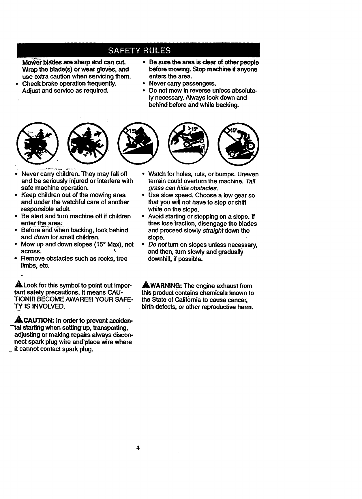
• Mow up and down slopes (15• Max), not
across. =
• Remove obstacles such as rocks,tree
limbs, etc.
,_Look forthis symbol to point out impor-
tant safety precautions. It means CAU-
TIONI!! BECOME AWAREI!! YOUR SAFE-
TY IS INVOLVED.
,_CAUTiON: In order to prevent acciden-
"tal sta:rtir_gwhen setting:up, transporting,
adjusting or making repairs always discon-
nect spark plug wire andplace wire where
_ it cannot contact spark plug.
• Watch for holes, ruts,or bumps. Uneven
terrain couldoverturnthe machine. Tall
grass can hide obstacles.
• Use slowspeed. Choose a low gear so
that you will not have to stopor shift
while on the slope.
• Avoid startingorstoppingon a slope. If
tires losefraction, disengage the blades
and proceed slowly straightdown the
slope.
• Do nottum onslopes unless nece.ssary,
and then, rum slowly and gradually
downhill,ifpossible.
_WARNING: The engine exhaust from
this product contains chemicals known to
the State of Calif_)mia to cause cancer,
birth defects, or other reproductive harm.
4
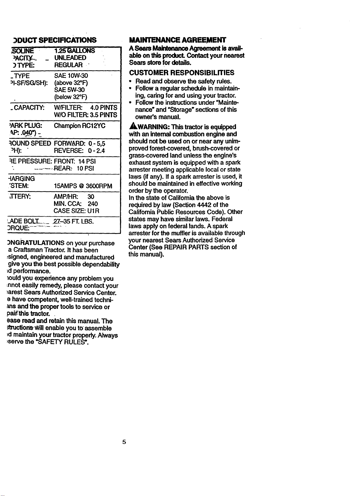
__DUCT SPECIFICATIONS
_SOUNE 1.25GALLoNs '
)ACI't'_-._ _ UNLEADED
) TYPE: REGULAR -
_TYPE SAE 10W-30
=I-SF/SG/SH): (above32°F)
SAE 5W-30
(below32°F)
. CAPACITY: W/FILTER: 4.0 PINTS
W/O FILTER:3.5 PINTS
'ARK PLUG: ChampionRC12YC
_
:IOUND SPEED FORWARD: O- 5,5
_H): REVERSE: 0,2.4
:_EPRESSURE: FRONT: 14 PSi
....... REAR.'-.10PSI
-IARGING
"STEM: 15AMPS @3600RPM
_'FrERY: AMP/HR: 30
MIN. CCA: 240
CASE SIZE: U1R
LADE BQLT_._..... 27....-35FT.LBS.
3RQUE:..............
)NGRATULATIONS on your purchase
a Craftsman Tractor. It has been
;signed, engineered and manufactured
give you the best possible dependability
_dperformance.
_ouldyou experience any problem you
Lnnoteasily remedy, please contactyour
;arest Sears Authorized Service Center.
e have competent, well-trained techni-
cs and the proper tools to service or
pail-this tractor.
ease read and retain this manual. The
_-'lmctionsWill enable you to assemble
_dmaintain your tractor propedy.Always
_servethe =SAFETY RULES'.
MAINTENANCE AGREEMENT
A Sears Maintenance Agreement is avail-
able on this product.Contact your nearest
Sears store fordet=ls.
CUSTOMER RESPONSIBILITIES
• Read and observe the safety rules.
• Follow a regularschedule in maintain-
ing, caring for and using your tractor.
• Followthe instructionsunder "Mainte-
nance"and "Storage"sections ofthis
owner's manual.
,_WARNING: This tractor isequipped
with an internal combustionengine and
should not be used on or near any unim-
proved forest-covered, brush-coveredor
grass-covered land unless the engine's
exhaust system is equipped with a spark
arrester meeting applicablelocal orstate
laws (if any). If a spark arrester is used,it
should be maintained in effective working
order by the operator.
In the state of Californiathe above is
required by law (Section 4442 ofthe
California Public Resources Code). Other
states may have similar laws. Federal
laws apply onfederal lands. A spark
arrester forthe muffleris available through
your nearest Sears Authorized Service
Center (See REPAIR PARTS section of
this manual).
5
I "NI" I
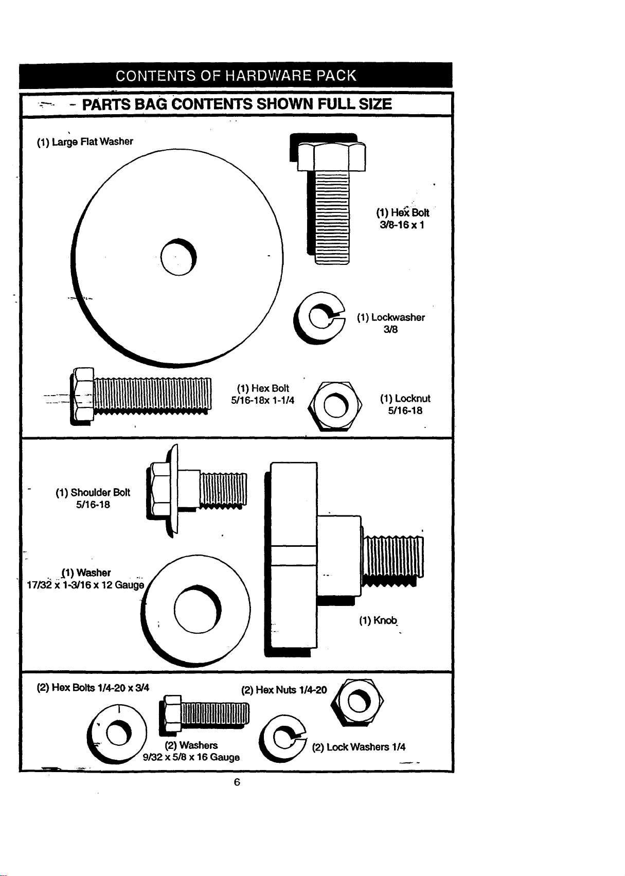
-_- - PARTS BAG CONTENTS SHOWN FULL SIZE
I
(1) Large Flat Washer
©
(1) He'xBolt
3/8-16 x I
(1) Lockwasher
3/8
(1) Hex Bolt
5116-18x 1-1/4
Q
I
(1) Locknut
5/16-18
(1) Shoulder Bolt
5/16-18
.... (1) Washer
17/32 x 1-3/16 x 12 Gauge
(1) Knob
(2) Hex Bolts 114-20x 3/4 (2) Hex Nuts 1/4-20 jv_,,_"_
@
(2) Washers (2) Lock Washers 114
9/32 x 5/8 x 16 Gauge __ _
6
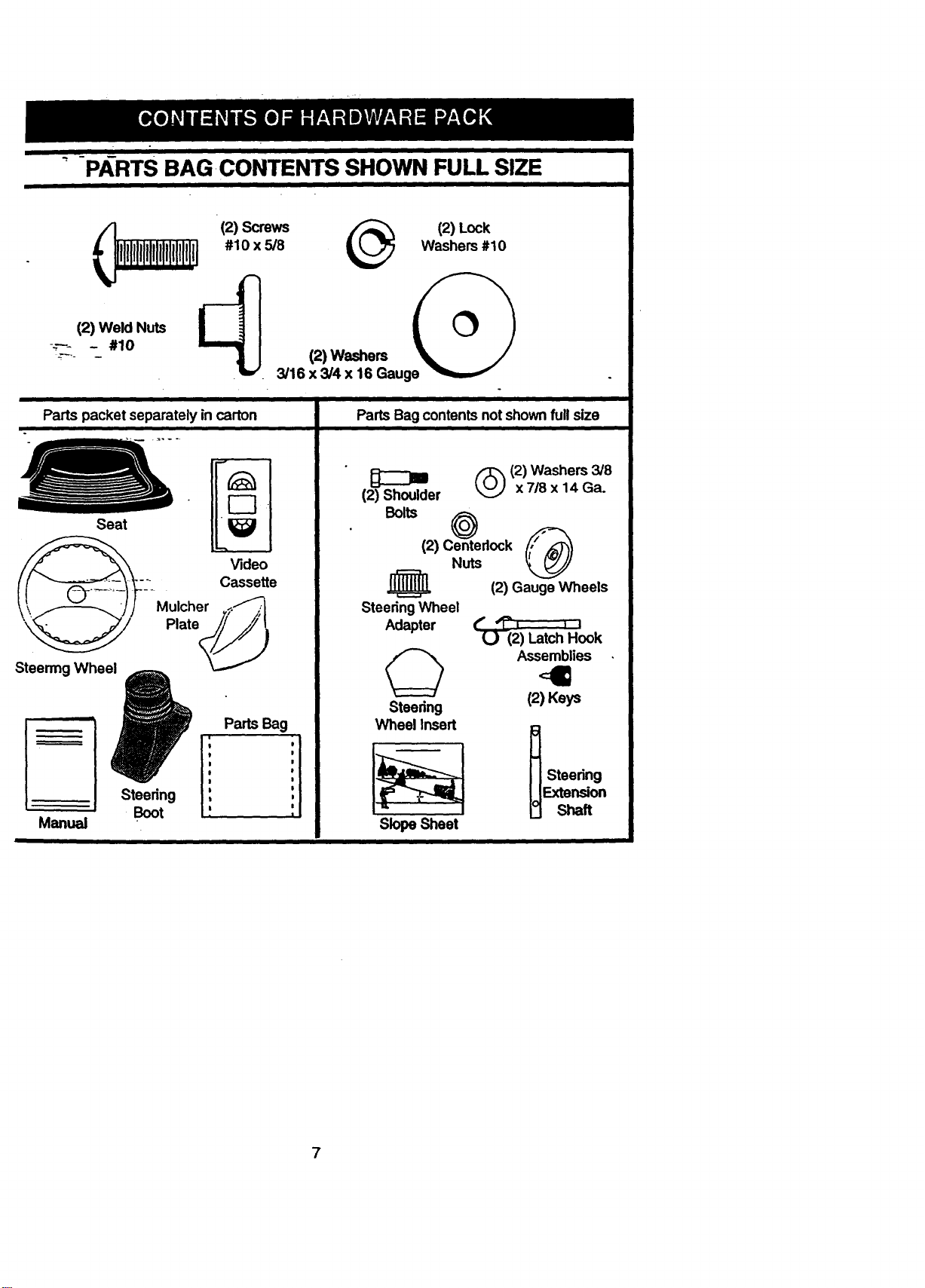
PARTS BAG,CONTENTS SHOWN FULL SIZE
(2) Weld Nuts
--.--- - #10
(2) Screws /_ (2) Lock
#10 x 5/8 _ Washers #10
J_ (2)Washers
3/16 x 3/4 x 16 Gauge
ii
Parts packet separately in carton Parts Bag contentsnot shownfull size
Seat "
Video
\ \ F--_--._ J J Mulcher
"____/ Plate
Steering Wheel
__lDi'
,
Manual
(_ (2) Washers 3/8
(2) Shoulder x 7/8 x 14 Ga.
Bolts 0
(2) CentedOCkNuts
J]_ (2) Gauge Wheels
SteeringWheel
Adapter C "_, ,
(.) (2) Latch Hook
Assemblies
Steering (2) Keys
Wheel Insert
Parts Bag
SlopeSheet
I
Steering
Extension
Shaft
7
.__
Your_pew_tractor has been _Lssembled at the factory with exception of those parts left
unassembled for shipping purposes. To ensure safe and proper operation of your tractor
all parts and hardware you assemble must be tightened securely. Use the correct tools
as necessary to insure proper tightness. Review the video cassette before you begin.
TOOLS REQUIRED FOR
ASSEMBLY
A socket wrenchset will make assembly
easier. Standard wrench sizes you need
are listed below.
(1) 9/16"wrench
(2)-/_7/1_ wrenches
(2) 1/2" wrench
(1) Umy knife
(1)Pliers
(1) 3/4" Socket w/
drive rachet
(1) PhillipsScrew-
driver
(1) Tire pressure
gauge
Wher_right-orJeft hand ;s mentioned in
this manual, it means, from your point of
view, when you are in the operating posi-
tion (seated behind the steering wheel).
TO REMOVE TRACTOR FROM
CARTON
UNPACK CARTON
• FLemo.ye_all_accessible loose parts and
parts-boxes from shipping carton (See
page 6).
• Cut, from top to bottom, along lines on
all four comers of shipping carton, and
lay panels flat.
• Check for any additional loose parts or
boxes and remove.
BEFORE ROLLING TRACTOR OFF
SKID
ATTACH STEERING WHEEL
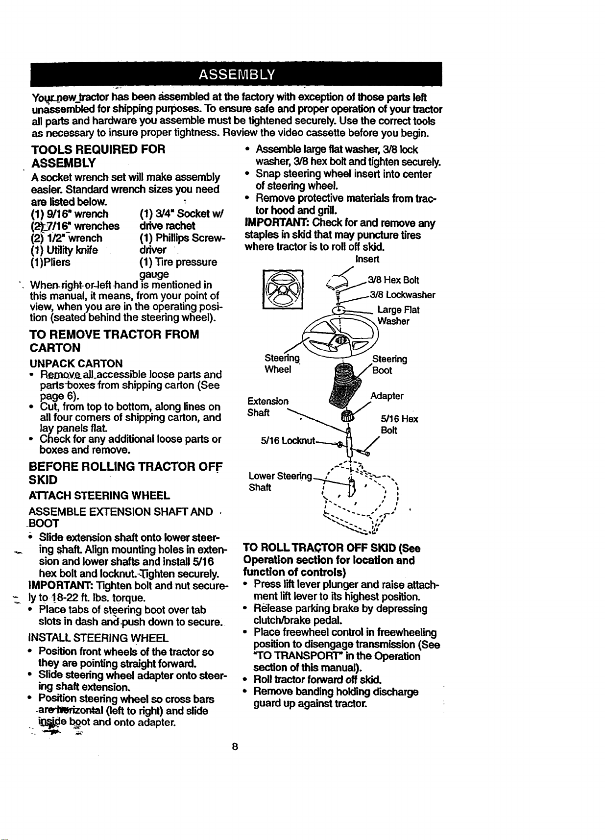
ASSEMBLE EXTENSION SHAFT AND •
_BOOT
;, Slide extension shaft onto lower steer-
ing shaft. Align mounting holes in exten-
sion and lower shafts and install 5/16
hex bolt and Iocknut.-:[ighten securely.
IMPORTANT: Tighten bolt and nut secure-
ly to t_8-22 ft. Ibs. torque.
• Place tabs of steering boot over tab
slots in dash and.push down to secure.
INSTALL STEERING WHEEL
• Position front wheels of the tractor so
they are pointing straight forward.
• Slide steering wheel adapter onto steer-
ing shaft extension.
• Position steering wheel so cross bars
-a_ontal (left to right) and slide
. iB_le l:_ot and onto adapter.
• Assemble large flat washer, 3/8 lock
washer, 3/8 hex bolt and tighten securely.
• Snap steering wheel insert into center
of steering wheel.
• Remove protective materials from trac-
tor hood and grill.
IMPORTANT: Check for and remove any
staples in skid that may puncture tires
where tractor is to roll off skid.
Insert
SHexBo.
I'._l _3/8 Lockwasher
I "_" I _ Lar e Ra"
Steering _ Steering
Wheel
TO ROLL TRACTOR OFF SKID (See
Operation section for location and
function of controls)
• Press lift lever plunger and raise attach-
ment lift lever to its highest position.
• Release parking brake by depressing
clutch/brake pedal.
• Place freewheel control in freewheeling
position to disengage transmission (See
"TO TRANSPORT" in the Operation
section of this manual).
• Roll tractor forward off skid.
• Remove banding holding discharge
guard up against tractor.
8
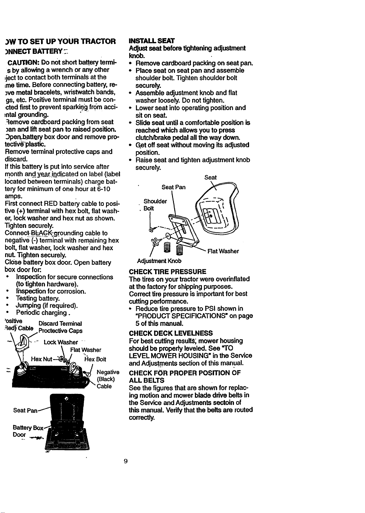
._W TO SET UP YOUR TRACTOR
)NNECT BATTERY.'_
B
'ositive
CAU'I_N: Do not short battery termi-
is by allowing a wrench or any other
_jectto contact both terminals at the
=metime. Before connecting battery, re-
)ve metal bracelets, wristwatch bands,
gs, etc. Positive terminal must be con-
,cted first to prevent sparking fr0m acci-
;ntal grounding.
:lemove cardboard packing from seat
_an and lift seat pan to raised position.
3perLbattQry box door and remove pro-
tectiVe- plastic.
Remove terminal protective caps and
discard.
If this battery is put into service after
month and_ye_ar,j ndicated on label (label
located between terminals) charge bat-
tery for minimum of one hour at 6-10
amps.
First connect RED battery cable to posi-
tive (+) terminal with hex bolt, flat wash-
er, lock washer and hex nut as shown.
Tighten securely.
Connect-Bt:AGl_:g_rounding cable to
negative (-) terminal with remaining hex
bolt, flat washer, lock washer and hex
nut. Tighten securely.
Close battery box door. Open battery
box door for:.
• Inspection for secure connections
(to tighten hardware).
Inspection for corrosion.
Testing battery.
Jumping (if required).
Periodic charging.
DiscardTerminal
ProctectiveCaps
Lock Washer "
Fiat Washer
I:lexBolt
Negative
(Black)
Seat Par
INSTALL SEAT
Adjust seat before tightening adjustment
knob.
• Remove cardboard packing on seat pan.
• Place seat on seat pan and assemble
shoulder bolt. Tighten shoulder bolt
securely.
• Assemble adjustment knob and flat
washer loosely. Do not tighten.
• Lower seat into operating position and
sit on seat.
• Slide seat until a comfortable position is
reached which allows you to press
clutch/brake pedal all the way down.
• Get off seat without moving its adjusted
position.
• Raise seat and tighten adjustment knob
securely.
Seat
Seat Pan
Shoulder
• Bolt
Flat Washer
AdjustmentKnob
CHECK TIRE PRESSURE
The fireson your tractorwere overinflated
at the factory forshippingpurposes.
Correcttire pressure isimportantfor best
cuttingperformance.
• Reduce tire pressure to PSI shown in
"PRODUCT SPECIFICATIONS" on page
5 of this manual.
CHECK DECK LEVELNESS
For best cutting resultS; mower housing
should be properly leveled. See =TO
LEVEL MOWER HOUSING" in the Service
and Adjust.ments section of this manual.
CHECK FOR PROPER POSITION OF
ALL BELTS
See the figures that are shown for replac-
ing motion and mower blade drive belts in
the Service and Adjustments sectoin of
this manual. Verify that the belts are routed
correctly.
Door
9
CHECK BRAKE SYSTEM "
After you leant how to operate your trac-
tor, check+tosee thatthe brake is properly
adjusted. See "TO ADJUST BRAKE" in
the Service and Adjustments section of
this manual.
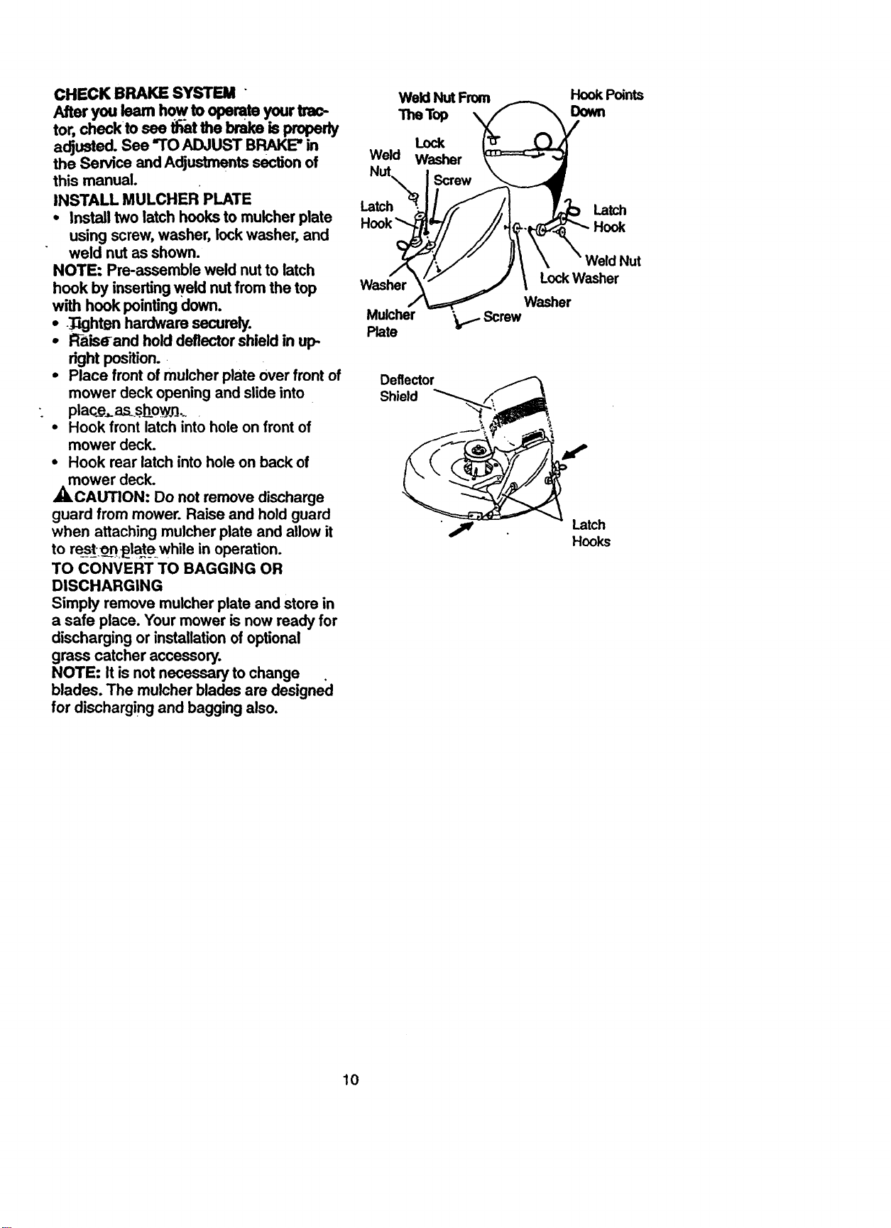
INSTALL MULCHER PLATE
• Install two latch hooks to mulcher plate
using screw, washer, lock washer, and
weld nut as shown.
NOTE: Pre-assemble weld nut to latch
hook by inserting weld nut from the top
with hook pointing down.
• T-lght_n hardware securely.
• Raise-and hold deflector shield in up
right position.
• Place front of mulcher plate over front of
mower deck opening and slide into
plac_e,.as_sb.owp_._
• Hook front latch into hole on front of
mower deck.
• Hook rear latch into hole on back of
mower deck.
,_CAUTION: Do not remove discharge
guard from mower. Raise and hold guard
when attaching mulcher plate and allow it
to re_s_tor_t_l_e while in operation.
TO CONVERT TO BAGGING OR
DISCHARGING
Simply remove mulcher plate and store in
a safe place. Your mower is now ready for
discharging or installation of optional
grass catcher accessory.
NOTE: It is not necessary to change
blades. The mulcher blades are designe_d
for discharging and bagging also.
Weld Nut From
The Top
Lock
Weld Washer
Latch
Washer
Mulcher
Plate
Screw
Deflector
Shield
HookP_n_
Down
Latch
Hook
Nut
Lock Washer
Washer
Latch
Hooks
10
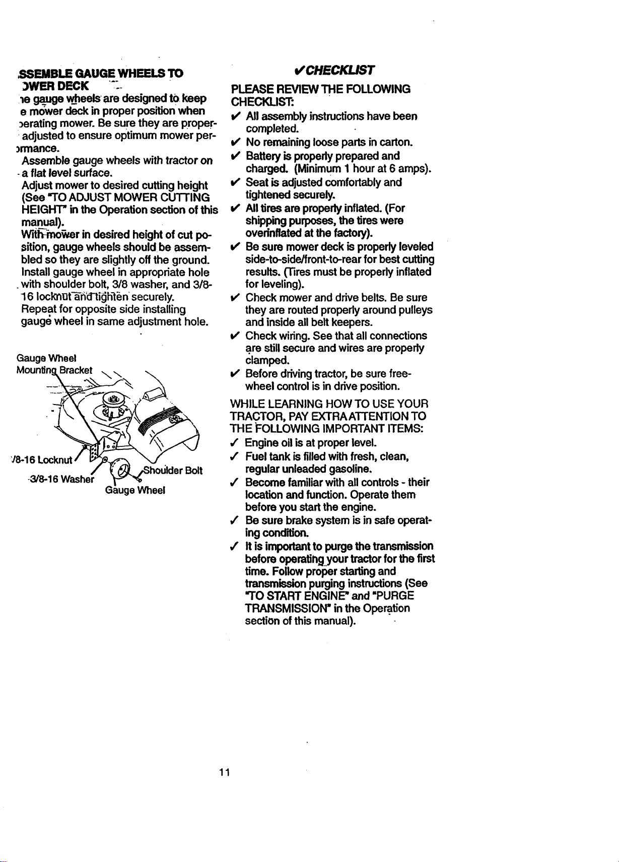
F..aSU!aAUaeW,m.S TO
_)WER DECK =;-
i'mgauge wh_eels are designed tO.keep
e mower deck in proper positionwhen
_erating mower. Be sure they are proper-
adjustedto ensure optimummower per-
)finance.
Assemble gauge wheels with tractor on
-a flat level surface.
Adjustmower to desired cuttingheight
(See "TO ADJUST MOWER CUTTING
HEIGHT" in the Operation section ofthis
manual).
Wit_er in desired height of cut po-
sition, gauge wheels shouldbe assem-
bled so they are slightlyoff the ground.
Install gauge wheel in appropriate hole
.with shoulder bolt, 3/8 washer, and 3/8-
16 Iocl_Ot-_h_d-ti_h-t_nsecurely.
Repeat for opposite side installing
gaug_ wheel in same adjustment hole.
Gauge Wheel
Bracket \
'J8-16
-3/8-16 Washer
e Wheel
v' CHECKLIST
PLEASE REVIEW THE FOLLOWING
CHECKLIST:
v' All assembly instructions have been
completed.
v' No remaining loose parts in carton.
v' Battery is properlyprepared and
charged. (Minimum 1 hourat 6 amps).
v" Seat is adjustedcomfortablyand
tightened securely.
V' All tires are properly inflated.(For
shippingpurposes,the tires were
ovednflated at the factory).
v' Be sure mowerdeck isproperlyleveled
side-to-side/fmnt-to-rear for best cutting
results. (Tiresmust be properlyinflated
for leveling).
v' Check mower and drivebelts.Be sure
they are muted properly around pulleys
and inside all belt keepers.
v' Check wiring.See that all connections
a.restillsecure and wires are properly
clamped.
v' Before drivingtractor,be sure free-
wheel controlis in drive position.
WHILE LEARNING HOW TO USE YOUR
TRA.CTOR, PAYEXTRAAT[ENTION TO
THE FOLLOWING IMPORTANT ITEMS:
/ Engine oil isat proper level.
•/ Fuel tank isfilled with fresh, clean,
regular unleaded gasoline.
,/ Become familiar with all controls- their
locationand function. Operate them
before you startthe engine.
,/ Be sure brake system isin safe operat-
ing condition.
,/ It is importantto purge the transmission
before operatingyour tractorfor the first
time. Followproper startingand
transmissionpurginginstructions(See
=TOSTART ENGINE" and "PURGE
TRANSMISSION" in the Operation
section of this manual).
11
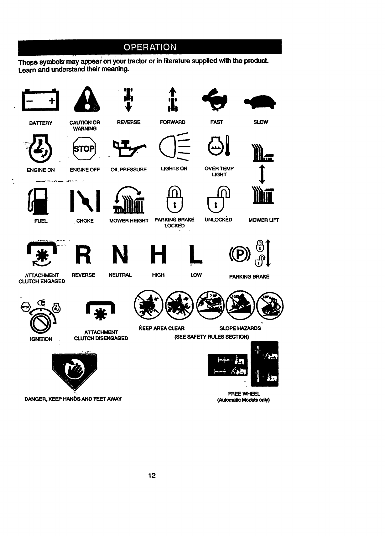
These symbolsmay appeaw;onyour tractor or in literature supplied with the product.
Learn and understand their meaning.
r
BATTERY CAUTION OR REVERSE FORWARD FAST SLOW
WARNING
ENGINE ON ENGINE OFF OIL PRESSURE UGHTS ON
FUEL CHOKE MOWER HEIGHT
PARKING BRAKE
LOCKED
OVER TEMP I
UGHT
UNLOCKI=D MOWER UFT
N H L
ATTACHMENT REVERSE NEUTRAL HIGH LOW PARKING BRAKE
CLUTCH ENGAGED
ATTACHMENT kEEP AREA CLEAR SLOPE HAZARDS
IGNITION CLUTCH DISENGAGED (SEE SAFETY RULES SECTION)
_o
DANGER, KEEP HANDS AND FEET AWAY
FREE WHEEL
(Auton_=Mod_ orgy)
12
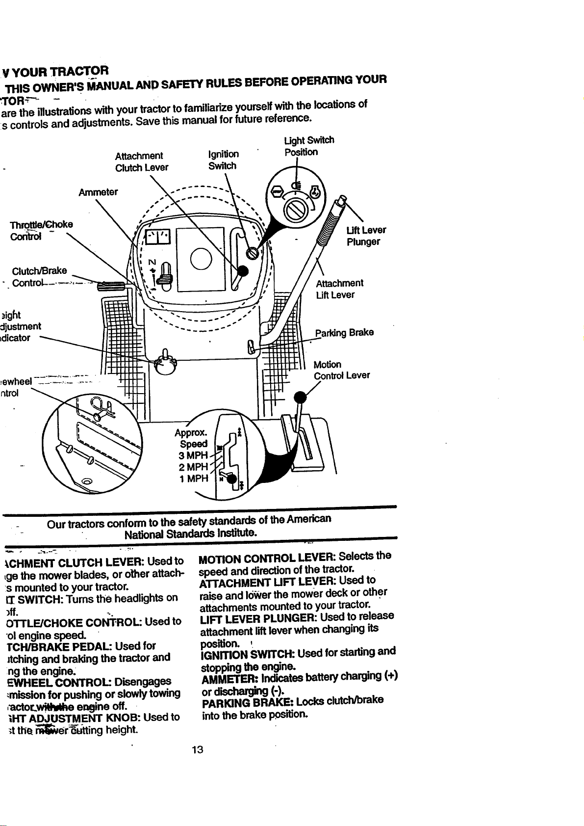
V YOUR TRACTOR
THIS OWNER'S _UAL AND SAFETY RULES BEFORE OPERATING YOUR
"FOR--"- -
are the illustrationswith your tractor to familiarize yourself with the locationsof
is controls and adjustments. Save this manual for future reference.
Attachment Ignition
Clutch Lever Switch
Ught Switch
Position
Ammeter
Throttle/Choke
Con'trol-
Lift Lever
Plunger
Clutch/Brake
aight
djustment
_dicator
:ewheel..............
ntrol
Attachment
LiftLever
ParkingBrake
Motion
ControlLever
Approx.
Speed
3
2 MPH"
1 MPH
i
Our tractors conform to the safety standards of the American
National Standards Institute.
I I I
_,CHMENT CLUTCH LEVER: Used to
tge the mower blades, or other attach-
s mounted to your tractor.
I_ SWITCH: Turns the headlights on
_ff.
OTTLF_JCHOKE coNT-ROL: Used to
ol engine speed.
TCH/BRAKE PEDAL: Used for
_ching and braking the tractor and
ng the engine.
EWHEEL CONTROL: Disengages
:mission for pushing or slowly towing
,'actor..w!8,ldl_ e_jine off.
_HT ADJUSTMENT KNOB: Used to
;t th_ _er_:Jtting height.
MOTION CONTROL LEVER: Selects the
speed and direction of the tractor.
ATTACHMENT LIFT LEVER: Used to
raise and lower the mower deck or other
attachments mounted to your tractor.
UFT LEVER PLUNGER: Used to release
attachment lift lever when changing its
position.,
IGNmON SWITCH: Used for starting and
stopping the engine.
AMMETER: Indicates battery charging (+)
or discharging (-).
PARKING BRAKE: Locks clutch/brake
into the brake pes_on.
13
I I I
The operation of any tractor can resultin foreigh objects thrownintothe
eyes, _hich canresult in severe eye damage. Always wear safety glasses
__or eye shields while operatingyour tractoror performing any adjustmentsOr
repairs.We recommend a wide visionsafety mask over the spectacles, or
standard safety glasses.
i
HOW TO USE YOUR TRACTOR
Your tractor is equipped with an operator
. presence sensing switch. When engine is
running, any attempt by the operator to
leave the seat without firstsetting the
parking brake willshutoff the engine.
=
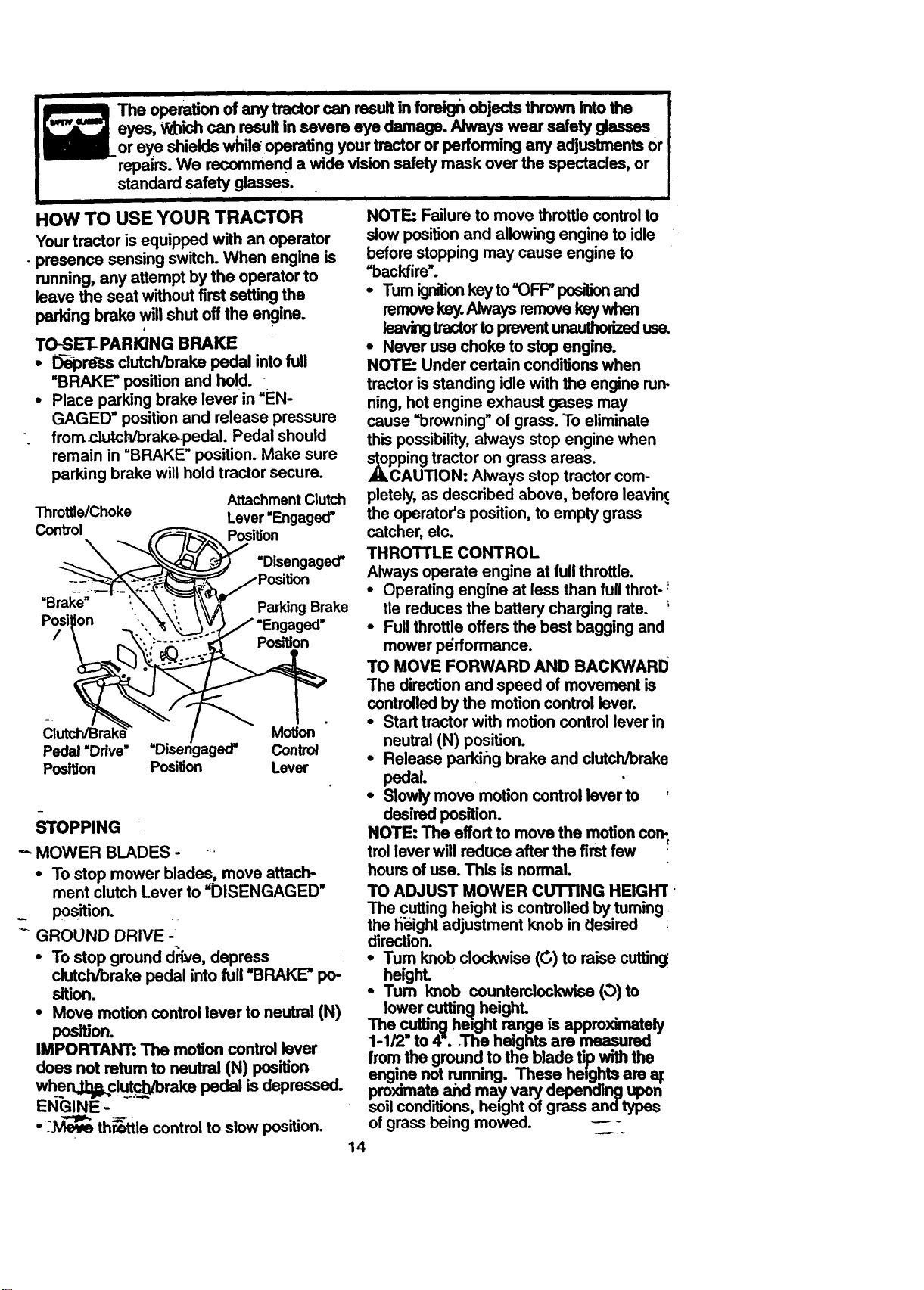
TO-SET-PARKING BRAKE
• D-epre_sclutch/brake pedal intofull
•BRAKE" positionand hold.
• Place parkingbrake lever in •EN-
GAGED" positionand release pressure
fromclutch/brak6pedal. Pedal should
remain in =BRAKE"position.Make sure
parking brake will holdtractor secure.
AttachmentClutch
Throttle/Choke Lever =Engaged'
Con_ol Position
=Disengaged'
"Brake" Parking Brake
/ Position
Motion
Pedal =Ddve" =Disengaged" Control
Position Position Lever
STOPPING
---MOWER BLADES -
• Tostop mower blades, move attach-
ment clutchLever to "blSENGAGED"
_ portion.
GROUND DRIVE -
• Tostop ground d-_ve,depress
clutch/brake pedal into full •BRAKE" po-
s'_on.
• Move motion control lever to neutral (N)
portion.
IMPORTANT: The motion control lever
does not return to neutral (N) position
w rU .cl d e pedeJisdepressed.
ENGINE -
•-:M_ th_ttle control to slow position.
i
NOTE: Failure to move throttle controlto
slowpositionand allowingengine to idle
before stopping may cause engine to
"backfire".
• Turnignitionkeyto•OFF" pesil_n and
removekey.Alwaysremovekeywhen
leavingtractortopreventu_ use,
• Never use choke to stop engine.
NOTE: Under certain conditionswhen
tractorisstanding idle with the engine run.
ning, hot engine exhaust gases may
cause =browning" of grass. To eliminate
this possibility,always stop engine when
_t_pping tractor on grass areas.
CAUTION: Always stop tractor com-
pletely,as described above, before leavinc
the operator'sposition,to empty grass
catcher,etc.
THROTTLE CONTROL
Always operate engine at full throttle.
• Operatingengine at less than fullthrot-_
tie reduces the battery charging rate.
• Full throttleoffersthe best bagging and
mowerpdrformance.
TO MOVE FORWARD AND BACKWARD
The directionand speed of movement is
controlled by the motioncontrol lever.
• Start tractorwith motioncontrol leverin
neutral(N) position.
• Release parking brake and clutch/brake
pedaL
• Slowlymove motioncontrol lever to '
desiredposition.
NOTE: The effortto move the motion co_
trolleverwill reduce after the firstfew
hoursof use.This is normal.
TO ADJUST MOWER CUTTING HEIGHT
The cuttingheight is controlledby turning
the I_ight adjustment knob in _lesired
direction.
•Tum knob clockwise (G) to raise cutting_
heighL
• "rum knob countemlockwise(0)to
lowercuttin(jheighL
The cuttingheight range is approximately
1-1/2" to4". The heights are measured
fromthe groundto the blade tip with the
engine notrunning. These heights are a€
proximateand may vary depending upon
soilconditions,height of grass and types
of grass being mowed. -- -
14
The average lawn should be cut to
approximately 2-1t2__.inches during the
cool,sgason and to over 3 inches dudng
hot r_nths'. For healthier and better
looking lawns, mow often and after
moderate growth.
For best cutting performance, grass
over 6 inches in height should be
-mowed twice. Make the first cut rela-
tively high; the second to desired height.
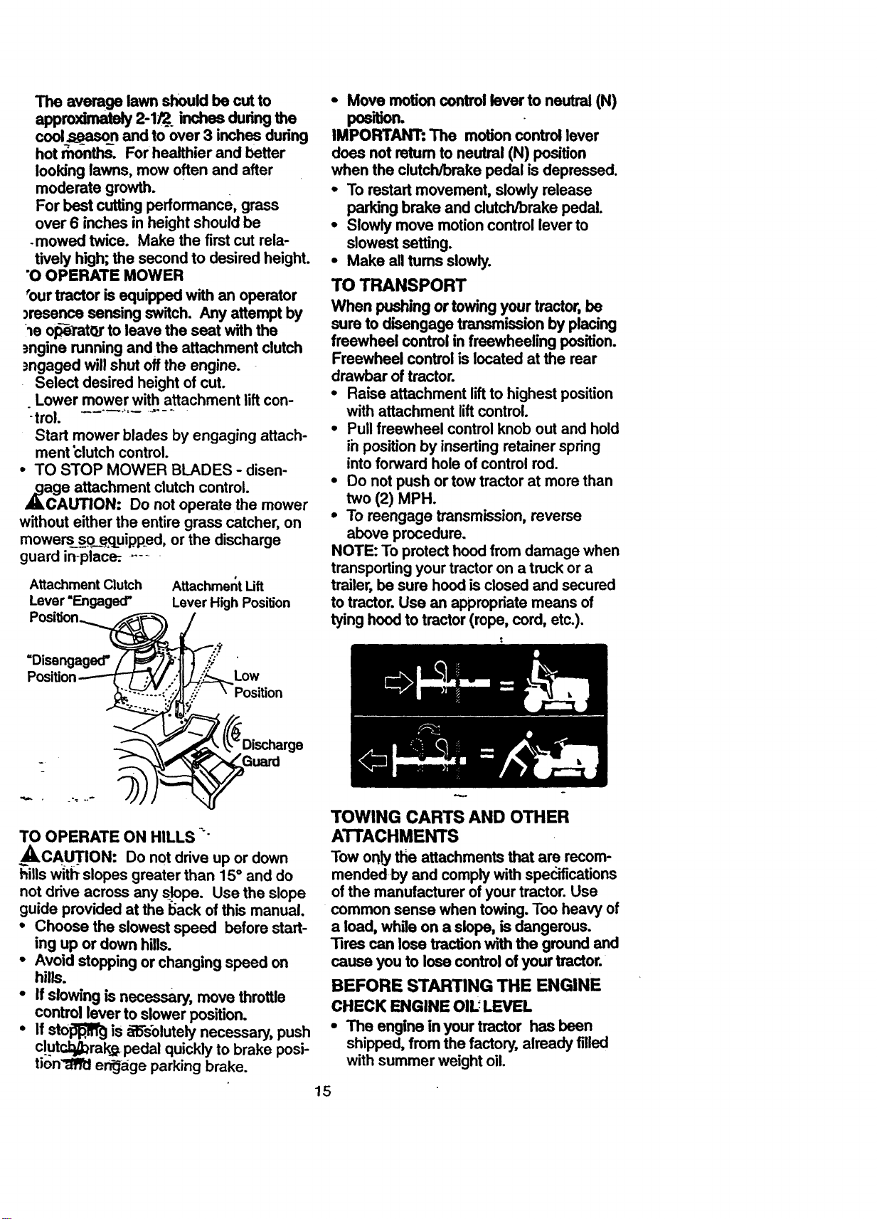
"OOPERATE MOWER
'our tractor is equipped with an operator
_resence sensing switch. Any attempt by
;_e op_l'atOj"to leave the seat with the
._nginerunning and the attachment clutch
._ngaged will shut off the engine.
Select desired height of cut.
. Lower mower with attachment lift con-
-trol. - .............
Start mower blades by engaging attach-
ment 'clutch control.
• TO STOP MOWER BLADES - disen-
,_ge attachment clutch control.
AUTION: Do not operate the mower
without either the entire grass catcher, on
mowers_s0_eP__uip.ped, or the discharge
guard in-place: ......
Attachment Clutch
Lever "Engaged"
Attachmer_tLift
Lever High Position
"Disengaged"
Low
Position
TO OPERATE ON HILLS ""
_CAUTION: Do not drive up or down
hills with slopes greater than 15• and do
not drive across any _.slope.Use the slope
guide provided at the l_ack of this manual.
• Choose the slowest speed before start-
ing up or down hills.
• Avoid stopping or changing speed on
hills.
• If slowing is necessary, move throttle
control lever to slower position.
• If sto_ is a_'s'olutely necessary, push
c!utcl_brake pedal quickly to brake posi-
tion'_J?_ler_jage parking brake.
• Move motion control lever to neutral (N)
position.
IMPORTANT: The motion control lever
does not return to neutral (N) position
when the clutch/brake pedal is depressed.
• To restart movement, slowly release
parking brake and clutch/brake pedal.
• Slowly move motion control lever to
slowest setting.
• Make all turns slowly.
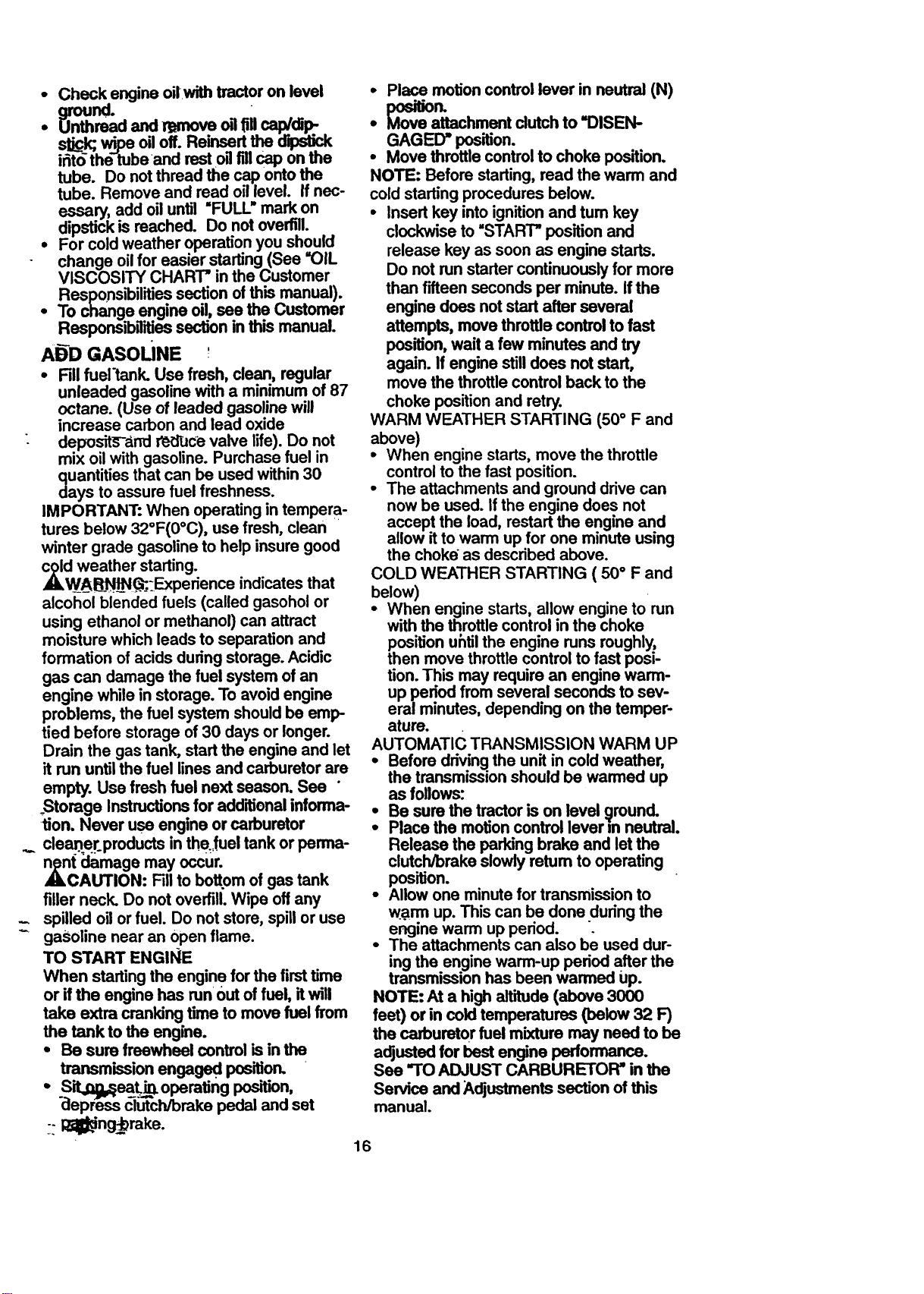
TO TRANSPORT
When pushing or towing your tractor, be
sure to disengage transmission by placing
freewheel control in freewheeling position.
Freewheel control is located at the rear
drawbar of tractor.
• Raise attachment lift to highest position
with attachment lift control.
• Pull freewheel control knob out and hold
ih position by inserting retainer spring
into forward hole of control rod.
• Do not push or tow tractor at more than
two (2) MPH.
• To reengage transmission, reverse
above procedure.
NOTE: To protect hood from damage when
transporting your tractor on a truck or a
trailer, be sure hood is closed and secured
to tractor. Use an appropriate means of
tying hood to tractor (rope, cord, etc.).
TOWING CARTS AND OTHER
ATTACHMENTS
Tow on!y the attachments that are recom-
mendedby and comply with spe(:.ifications
of the manufacturer of your tractor. Use
common sense when towing. Too heavy of
a load, whge on a slope, is dangerous.
"i]res can lose traction with the ground and
cause you to lose control of your tractor.
BEFORE STARTING THE ENGINE
CHECK ENGINE OIL" LEVEL
• The engine in your tractor has been
shipped, from the factory, already filled
with summer weight oil.
15
• Check engine oilwith tractor on level
oDrogl
rid.
• On.read and o,6ncap/ep
wipe oil off. Reinsert the 0"_-tJck
ifitdthe tubeand rest og fillcap on the
tube. Do not thread the cap onto the
tube. Remove and read oil level. If nec-
essary, add oil until •FULL • mark on
dipstick is reached. Do not overfill.
• For cold weather operation you should
change oil for easier starting (See "OIL
VISCOSITY CHART" in the Customer
Responsibilities section of this manual).
• To change engine oil, see the Customer
Responsibgities section in this manual.
ADD GASOUNE '
• Fill fueltank. Use fresh, clean, regular
unleaded gasoline with a minimum of 87
octane. (Use of leaded gasoline will
increase carbon and lead oxide
deposit_,nd fe_Jce valve life). Do not
mix oil with gasoline. Purchase fuel in
uantities that can be used within 30
ays to assure fuel freshness.
IMPORTANT: When operating in temper a-
tures below 32°F(0°C), use fresh, clean
winter grade gasoline to help insure good
weather starting.
_Experience indicates that
alcohol blended fuels (called gasohoi or
using ethanol or methanol) can attract
moisture which leads to separation and
formation of acids during storage. Acidic
gas can damage the fuel system of an
engine while in storage. To avoid engine
problems, the fuel system should be emp-
tied before storage of 30 days or longer.
Drain the gas tank, start the engine and let
it run until the fuel lines and carburetor are
empty. Use fresh fuel next season. See "
Storage Instructions for additional informa-
tion. Never use engine or carburetor
... cleaner.products in the_.fuel tank or perma-
nt damage may occur.
CAUTION: Fill to bottom of gas tank
filler neck. Do not overfill. Wipe off any
_ spilled oil or fuel. Do not store, spill or use
gasoline near an open flame.
TO START ENGINE
When starting the engine for the first time
or if the engine has run Out of fuel, it will
take extra cranking time to move fuel from
the tank to the engine.
• Be sure freewheel control is in the
bansmission engaged position.
• Sitj:_g_eat,_:_operating position,
_epr_ss a_ch/brake pedal and set
gii_ng_rake.
• Place motion control lever in neutral (N)
"'111.
• Move attachment dutch to =DISEN-
GAGED" position.
• Move throttle control to choke position.
NOTE: Before starting, read the warm and
cold starting procedures below.
• Insert key into ignition and tum key
clockwise to "START" position and
release key as soon as engine starts.
Do not run starter continuously for more
than fifteen seconds per minute. If the
engine does not start after several
attempts, move throttle control to fast
position, wait a few minutes and try
again. If engine still does not start,
move the throttle control back to the
choke position and retry.
WARM WEATHER STARTING (50 ='F and
above)
• When engine starts, move the throttle
control to the fast position.
• The attachments and ground drive can
now be used. If the engine does not
accept the load, restart the engine and
allow itto warm up for one minute using
the choke as described above.
COLD WEATHER STARTING ( 50 ° F and
below)
• When engine starts, allow engine to run
with the throttle control in the choke
position uhtil the engine runs roughly,
then move throttle control to fast posi-
tion. This may require an engine warm-
up period from several seconds to sev-
eral minutes, depending on the temper-
ature.
AUTOMATIC TRANSMISSION WARM UP
• Before drivingthe unitin cold weather,
the transmissionshould be warmed up
as follows:
• Be sure the tractor is on level _lround.
• Place the motion control lever m neutral.
Release the parking brake and let the
clutch/brake slowly return to operating
position.
• Allow one minute for transmission to
warm up. This can be done during the
engine warm up period.
• The attachments can also be used dur-
ing the engine warm-up period after the
transmission has been warmed Up.
NOTE: At a high altitude (above 3000
feet) or in cold temperatures (below 32 F)
the cmburetor fuel mixture may need to be
adjusted for best engine performance.
See "TO ADJUST CARBURETOR" in the
Service and Adjustments section of this
manual.
16
'.URGETRANSMISSION
CAUTION:Neverengageordisen-
agefraewheel lever while the engine is
inning.
b ensure proper operation andperfor-
_ance, it is recommended that the trans-
mission be purged before operating tractor
_r the first time. This procedure will
_move any trapped air inside the trans-
mission which may have developed during
;hipping of your tractor.
IMPORTANT: Should your transmission
'equire removal for service or replace-
Tlent;_t should be purged after reinstalla-
"onbefore operating the tractor.
Place tractor safely on level surface with
engine off and parking brake set.
. Disengage transmission by placing free-
-wheel d-o-n'tT6f'i'firf_e-€wheeling position
(See =TO TRANSPORT" in this section
of manual).
• Sitting in the tractor seat, start engine.
After the engine is running, move throt-
tle control to slow position. With motion
control lever in neutral (N) position,
slowly_di__sengage clutch/brake pedal.
• Move-metion eentrol lever to full forward
position and hold for five (5) seconds.
Move lever to full reverse position and
hold for five (5) seconds. Repeat this
procedure three (3) times.
NOTE: During this procedure there will be
no movement of drive wheels. The air is
being removed from hydraulic drive sys-
tem.
• Move motion control lever to neutral (N)
osition. Shut off engine and set parking
rake.
• Engage transmission by placing free-
wheel control in driving position (See
"TO TRANSPORT" in this section of
"-manual). ....
• Sitting in the tractor seat, start engine.
After the engine is runni_ig, move throt-
tle control to half (1/2) speed. With
- motion control lever in neutral (N) posi-
tion, siowly disengage clutch/brake
pedal.
• Slowly move motion'control lever for-
ward; after the tractor moves approxi-
mately five (5) feet, slowly move motion
control lever to reverse position. After
the tractor moves approximately five (5)
feet return the motion control lever to
the neutral (N) position. Repeat this pro-
cedu_g,_Jth .U_-motion control lever
thr_e (3_-tim_. . .
• Yo_cto_is now purged and reaoy ;or
norm-dT'ope-Tation.
MOWING TIPS
• "life chains cannot be used when the
mower housing is attached to tractor.
• Mower should be properly leveled for
best mowing performance. See =TO
LEVEL MOWER HOUSING" in the
Service and Adjustments section of this
manual.
• The left hand side of mower should be
used for trimming.
• Drive so that clippings are discharged
onto the area that has been cut. Have
the cut area to the right of the tractor.
This will result in a more even distn'bu-
tion of clippings and more uniform cut-
ting.
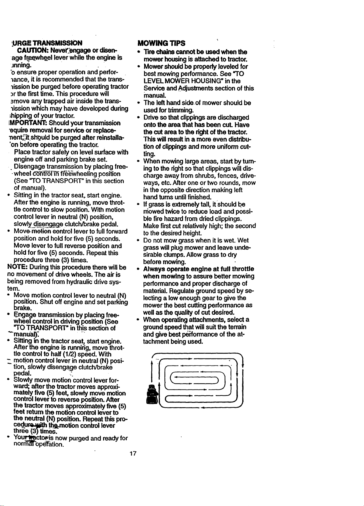
• When mowing large areas, start by turn-
ing to the right so that clippings will dis-
charge away from shrubs, fences, drive-
ways, etc. After one or two rounds, mow
in the opposite direction making left
hand turns until finished.
• If grass is extremely tall, it'should be
niowed twice to reduce load and possi-
ble fire hazard from dried clippings.
Make first cut relatively high; the second
to the desired height.
• Do not mow grass when it is wet. Wet
grass will plug mower and leave unde-
sirable clumps. Allow grass to dry
before mowing.
• Always operate engine at full throttle
when mowing to assure better mowing
performance and proper discharge of
material. Regulate ground speed by se-
lecting a low enough gear to give the
mower the best cutting performance as
well as the quality of cut desired.
• When operating attachments, select a
ground speed that will suit the terrain
and give best i:_formance of the at-
tachment being used.
17
MULCHING MOWING TIPS
mPORTAN'r'.Forbestperformance,keep
mower housing free of bu_-up grass and
tra_-T'f.Clean after each use.
• The special mulching blade will recut
the grass clippings many times and
reduce them in size so that as they fall
onto the lawn they will disperse into the
grass and not be noticed. Also, the
mulched grass will biodegrade quickly
to provide nutrients for the lawn. Always
mulch with your highest engine (blade)
speed as this will provide the best recut-
_--ting.action of the blades.
• "-Avoid cutting your lawn when it is wet.
Wet grass tends to form clumps and
interferes with the mulching action. The
best time to mow your lawn is the early
aftemoon.-At-this time the grass has
dried and the newly cut area will not be
exposed to the direct sun.
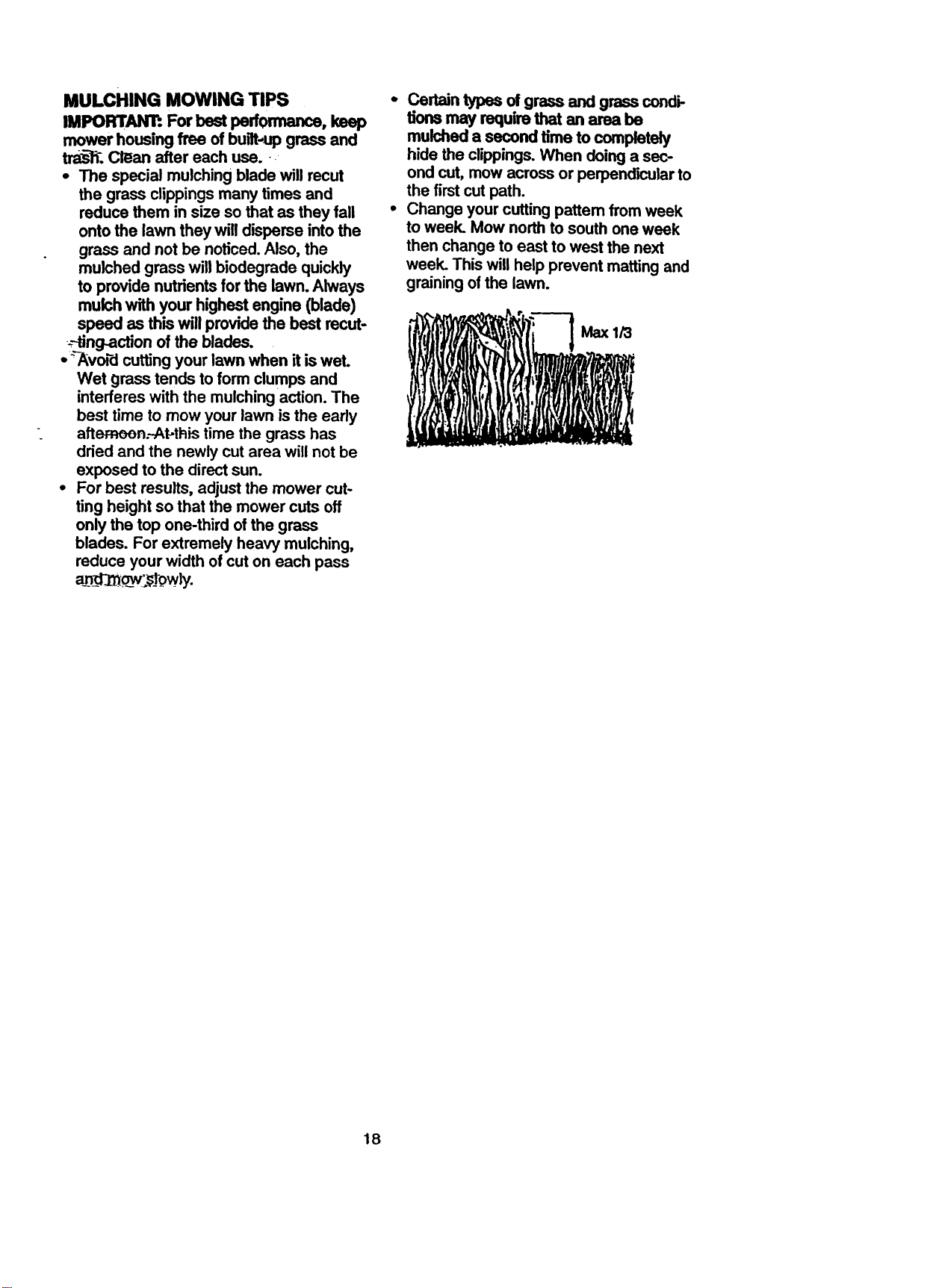
• For best results, adjust the mower cut-
ting height so that the mower cuts off
only the top one-third of the grass
blades. For extremely heavy mulching,
reduce your width of cut on each pass
_n-_rm-o_v_-o.wly.
• Certain types of grass and grass condi-
tions may require that an area be
mulched a second time to completely
hide the clippings. When doing a sec-
ond cut, mow across or perpendicular to
the first cut path.
• Change your cutting pattem from week
to week. Mow north to south one week
then change to east to west the next
week. This will help prevent matting and
graining of the lawn.
18
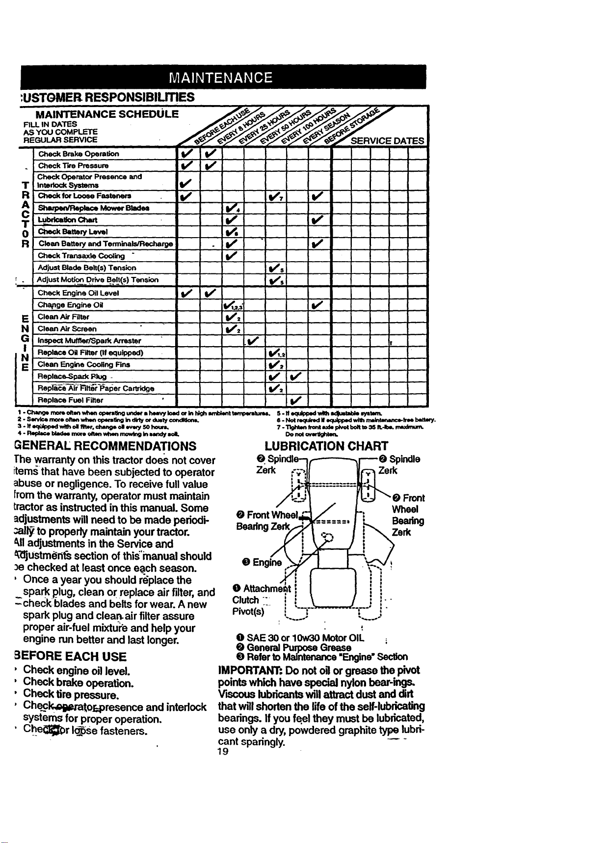
:USTOMER RESPONSIBILITIES
MAINTENANCE SCHEDULE
FILL IN DATES
AS YOU COMPLETE
REGULAR SERVICE 3ERVICE DATES
c_ o_o_ V' I,"
Check T'wePressure V' li_
Check Operator Presence and
_ Loo_F,=,_,re I/ V', V'
==ry v'.
R c_an BatteryandTem_ina_mecharge I/
Check Transaxle Cooling V'
Adjust Blade Belt(s) Tension llk/s
Adi.stMo"t__D_,aa#Lt(p)T_s_ V',
Check Engine Oil Level _
HE Clean Air Filter
Clean Air Screen
.9 1 Inspect Muffk_r/Spark Attester .
N Replace Oil FHter (If equipped) j I¢_1.=
Clean Engine Coolir_gFins [tb/e
Replace.Spa_P.lug .. _ q5_
Rep_ce--Air_'l_te'rPal_er Cartridge ,fieF2
Replace Fuel Filter ' tf
2 - Se_.4 m_e olt_ whon ol_ra_g In d_ty_r dusty_
4 - P,_:dae_bla_m mu_'eoltenvd_ movdr_ In uandya_l.
GENERAL RECOMMENDATIONS
The warranty on this tractor does not cover
_tems that have been subjected to operator
abuse or negligence. To receive full value
from the warranty, operator must maintain
tractor as instructed in this manual. Some
adjustments will need to be made pedodi-
;all_ to properly maintain your tractor.
_,11adjustments in the Service and
_ustm_nfi section of this"manual should
3e checked at least once eoch season.
' Once a year you should r_place the
spark plug, clean or replace air filter, and
_checklblades and belts for wear. A new
spark plug and clean.air filter assure
proper air-fuel mixtur'e and help your
engine run better and last longer.
_EFORE EACH USE
' Check engine oil level.
' Check brake operation.
• Check tire pressure.
' Ches_or=presence and interlock
systems for proper operation.
' Chei_r Io_se fasteners.
s -Not r_p..dmdII _p.dp,p_a wtm_h'_ ba,_.
7 *_ frc_t ax_ l_k_otbolt_ _ R.-Ib_ mmdmum.
LUBRICATION CHART
Zerk Zerk
0 FrontWheel
-'ront
Wheel
Beadng
Zerk
e Engine
0
Clutch "
Pivot(s) ; , ,
O SAE 30 or 10w30 Motor OIL
_ General Purpose Grease
Refer to Maintenance "Engine"Section
IMPORTANT: Do not oil or grease the pivot
points which have special nylon bear-ings_
Viscous lubricants will attract dust and dirt
that w'll shorten the life of the self-lubdcaUng
bearings. If you f.eel they must be lubricated,
use only a dry, powdered graphite type lubri-
cant sparingly. _ -
19
TRACTOR
Always obsewe safety rules when per-
forming any maintbnance. •
BRAKE OPERATION
If tractor requires more than six (6) feet
stopping distance at high speed in highest
gear, then brake must be adjusted. (See
=TO ADJUST BRAKE" in the Service and
Adjustments section of this manual).
TIRES
• Maintain proper air pressure in alltires
(See "PRODUCT SPECIFICATIONS"
• --onpage 5 ofthis manual).
Keel5 tires free of gasoline, oil, or insect
control chemicalswhich canharm rub-
ber.
• Avoid stumps, stones, deep ruts, sharp
objects_md-othel"hazards that may
cause tire damage.
NOTE: To seal tire puncturesand prevent
flat tires due to slow leaks, tire sealant
may be purchased from your localparts
dealer. Tire sealant also prevents tire dry
rotand corrosion.
BLADIE C..ABE _
For bes-rresolts mower blades must be
kept sharp. Replace bent or damaged
blades.
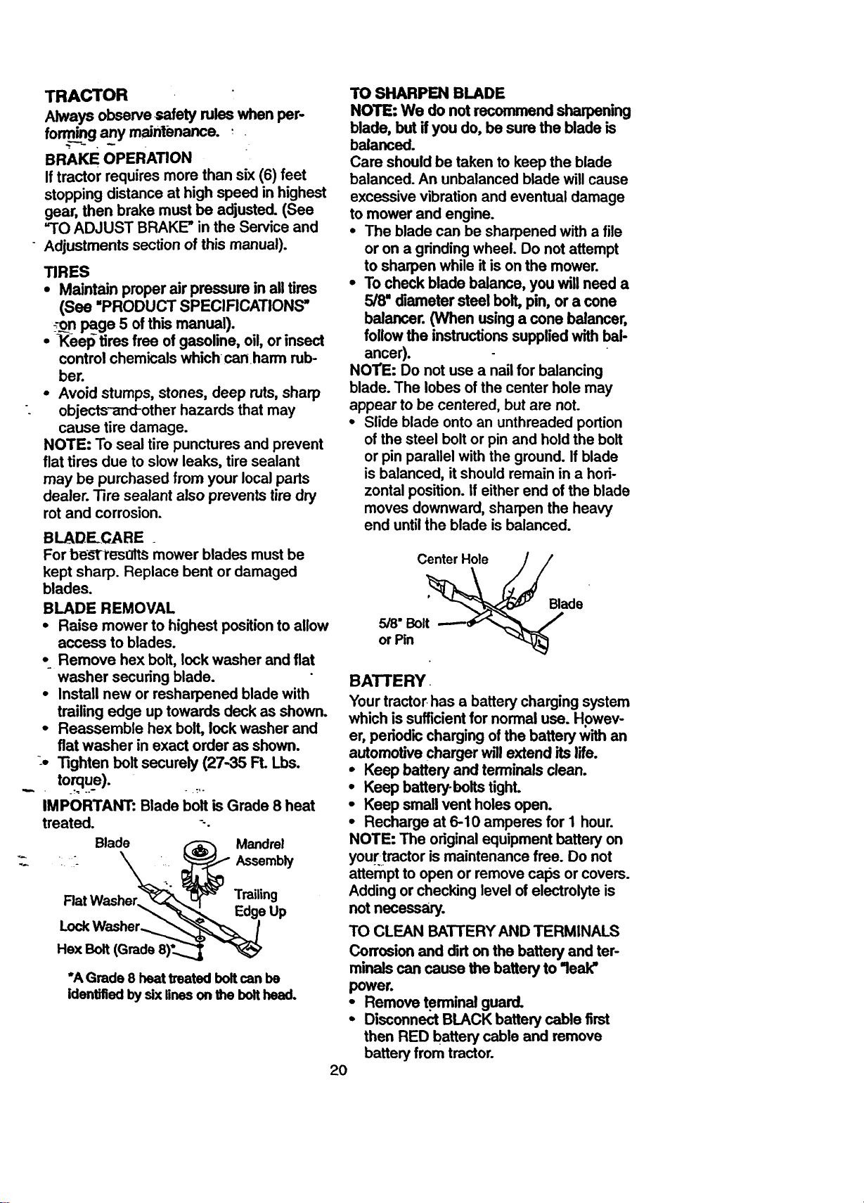
BLADE REMOVAL
• Raise mower to highest position to allow
access to blades.
• Remove hex bolt, lock washer and flat
washer securing blade.
• Install new or resharpened blade with
trailing edge up towards deck as shown.
Reassemble hex bolt, lock washer and
fiat washer in exact order as shown.
Tighten bolt securely (27-35 Ft. Lbs.
to..m.,ue). .....
IMPORTANT: Blade bolt is Grade 8 heat
treated. --.
Blad___,_ Mandrel
- Assembly
Flat Was _" Trailing
Edge Up
Lock W_er_--__J
Hex Bolt (Grade 8)_j_
*A Grade 8 heat treated boltcan be
identified by sixlineson the bolthead.
1"OSHARPEN BLADE
NOTE: We do not recommend sharpening
blade, but if you do, be sure the blade is
balanced.
Care should be taken to keep the blade
balanced. An unbalanced blade will cause
excessive vibration and eventual damage
to mower and engine.
• The blade can be sharpened with a file
or on a grinding wheel. Do not attempt
to sharpen while it is on the mower.
• To check blade balance, you will need a
5/8" diameter steel bolt, pin, or a cone
balancer. (When using a cone balancer,
follow the instructions supplied with bal-
ancer).
NOTE: Do not use a nail for balancing
blade. The lobes of the center hole may
appear to be centered, but are not.
• Slide blade onto an unthreaded portion
of the steel bolt or pin and hold the bolt
or pin parallel with the ground. If blade
is balanced, it should remain in a hori-
zontal position. If either end of the blade
moves downward, sharpen the heavy
end until the blade is balanced.
Center Hole
p
5/'8"BoR
or Pin
Blade
BATTERY
Your tractorhas a batterychargingsystem
whichis sufficientfor normal use. Howev-
er, periodicchargingofthe battery withan
automotivecharger willextend itslife.
• Keep battery and terminalsclean.
• Keep battery-boltstight.
• Keep small vent holes open.
• Recharge at 6-10 amperes for I hour.
NOTE: The originalequipment batteryon
your;tractoris maintenancefree. Do not
attemptto open or removecai_sor covers.
Addingor checking levelof electrolyteis
not necessary.
TO CLEAN BATI'ERY AND TERMINALS
Corrosion and dirt on the battery and ter-
minals can cause the battery to "leak"
power.
• Remove terminal guard.
• Disconnect BLACK battery cable first
then RED battery cable and remove
battery from tractor.
2O
Rinse the battery with plain water and
dry. " ---
Clean terminals an8battery cable ends
with_"re brush untilbright.
Coat terminals with grease orpetroleum
jelly.
Reinstall battery (See "CONNECT BAT-
TERY" in the Assembly section ofthis
manual).
-BELTS
"heck V-belts for deterioration and wear
Lfter 100 hours of operation and replace if
lecessa_ry_The belts are not adjustable.
epla'¢ebelts if they begin to slip from
_eaL
"RANSAXLE COOLING
"hetransmissionfan and cooling fins
;houldbe-keprcleatt tOassure proper
-ooling.
_)onotdttempt to clean fan or transmis-
;ionwhile engine is runningor while the
•ansmission is hot.
Inspect cooling fan to be sure fan
blades are intact and clean.
• Inspect coolin9 fins for dirt, grass clip-
pings_d-_-t;h_'-rnaterials. To prevent
damage to seals, do not use com-
pressed air or high pressure sp.(ayerto
clean cooling fins.
rRANSAXLE PUMP FLUID
The transaxle was sealed at the factory
_nd fluid maintenance is not reqiJiredfor
_.helifeof the transaxle. Should the
_ransaxle ever leak or require servicing,
contact your nearest authorized service
3enter.
EN_GINE
LUBRICATION
_Llly use high quality detergent oilrated
NithAPI service classificationSF, SG, or
;H. Select the oil's SAE viscositygrade
_ccording to your expected operating tem-
)erature.:_ .i
SAE VISCO61TYGRADES
4
• . . , , , .
TEMPER_lrtmE_ N/TIClPATEDBEFORENEXTOILOtk,_E
3hange the onafter every 50 hours of
)Peratioo,,.cjr_-_tleasLonce a year ifthe
ractor'isnot used for 50 hours in one
pear;-'
Check the crankcase oil level before start-
ing the engine and alter each eight (8)
hours of operation. Tighten oilfill cap/dip-
stick securely each time you check the oil
level.
TO CHANGE ENGINE OIL
Determine temperature range expected
before oil change. All oil must meet API
service classification SF, SG, or SH.
• Be sure tractor is on level surface.
- Oil will drain more freely when warm.
• Catch oil in a suitable container.
• Remove oHfill cap/dipstick. Be careful
not to allow dirt to enter the engine
when changing oil.
• Remove drain plug.
• After oil has drained completely, replace
oil drain plug and tighten securely.
• Refill engine with oil through oil fill dip-
stick tube. Pour slowly. Do not overfill.
For approximate capacity see =PROD-
UCT SPECIFICATIONS" on page 5 of
this manual.
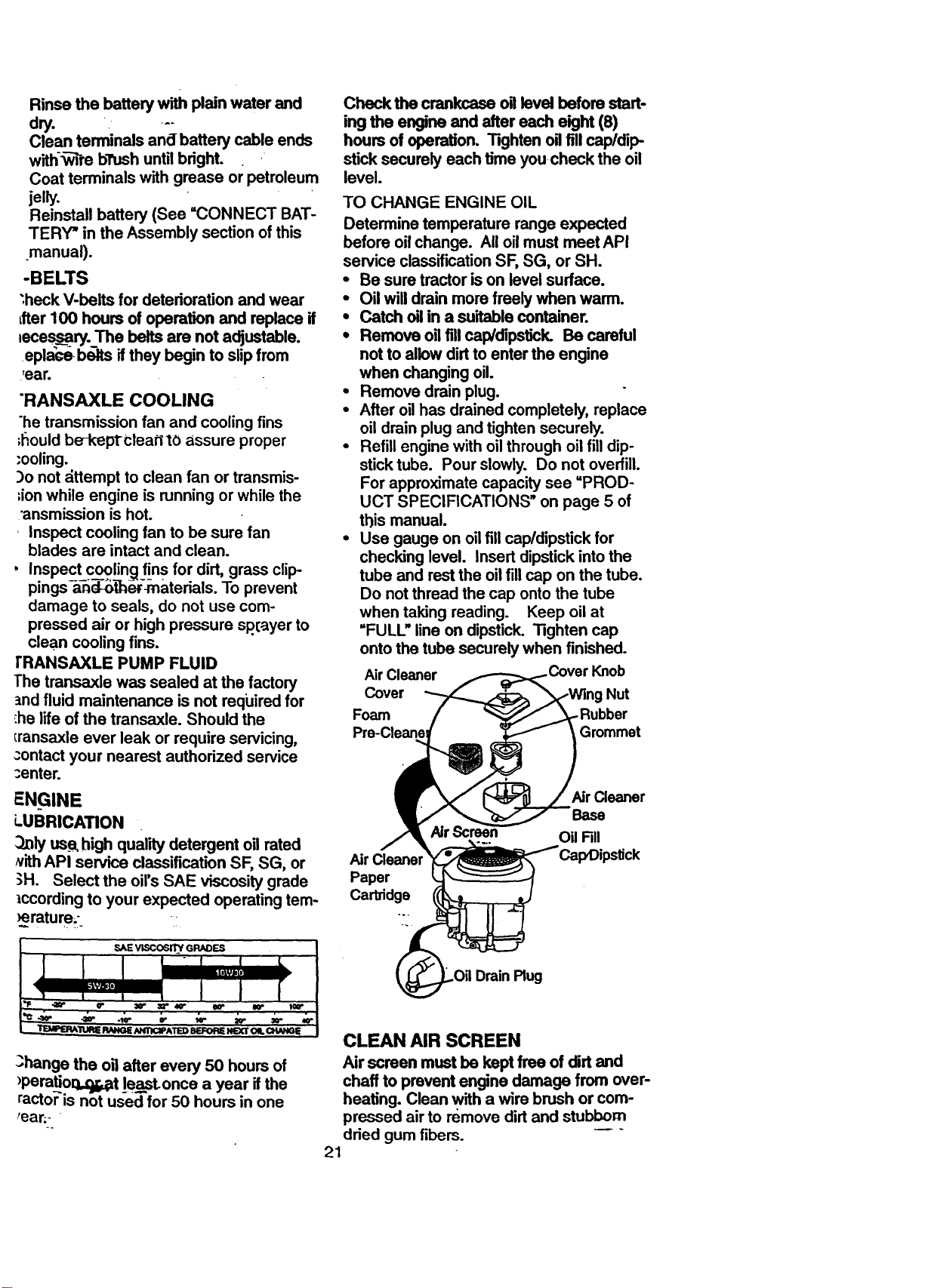
• Use gauge on oil fill cap/dipstick for
checking level. Insert dipstick into the
tube and rest the oil fill cap on the tube.
Do not thread the cap onto the tube
when taking reading. Keep oil at
"FULL" line on dipstick. Tighten cap
onto the tube securely when finished.
AirCleaner Knob
Cover Nut
Foam
Pre-Cleane_ Grommet
Air Cleaner
Oil Fill
Paper
Cartridge
Drain Rug
CLEAN AIR SCREEN
Air screen must be kept free of dirt and
chaff to preventengine damage from over-
heating. Clean with a wire brush or com-
pressed airto remove dirtand stubborn
dried gumfibers. _ -
21
CLEAN AIR INTAKE/COOUNG AREAS
To insure proper _._ng, make sure the
grass screen, cooling fins, and other
external surfaces of the engine are kept
clean at all times.
Every 100 hours of operation (more often
under extremely dusty, dirty conditions),
remove the blower housing and other
cooling shrouds. Clean the cooling fins
and external surfaces as necessary. Make
sure the cooling shrouds are reinstalled.
NOTE: Operating the engine with a
blocked grass screen, dirty or plugged
cooling.fins, and/or cooling shrouds re-
mOved_Nill cause engine damage due to
overheating.
AIR FILTER
Your engine will not run properly using a
dirty air-fitter.-Ctean the foam pre-cleaner
after every 25 hours of operation or every
season. Service paper cartridge every
100 hours of operation or every season,
whichever occurs first.
Service air cleaner more often under dusty
conditions.
= Remove knob and cover.
• Re_i_-v_-g nut and air cleaner from
base.
TO SERVICE PRE-CLEANER
• Slide foam pre-cleaner off cafffidge.
• Wash it in liquid detergent and water.
• Squeeze it dry in a clean cloth. Allow it
to dry.
,; Saturate it in engine oil. Wrap it in
clean, absorbent cloth and squeeze to
remove excess oil.
TO SERVICE CARTRIDGE
-o Replace a dirty, bent, or damaged car-
tridge.
NOTE: Do not wash the paper cartridge
or use pressurized air, as this will damage
the cartridge. :.
• Reinstall the pre-cleaner (cleaned and
oiled) over the paper cartridge.
• Reassemble air cleaner, wing nut, cover
and tighten kno_ securely.
ENGINE OIL FILTER
Replace the engine oil filter every season
or every other oil change if the tractor is
used more than 100 hours in one year.
• Drain oil from engine crankcase (See
"TO CHANGE ENGINE OIL • in this sec-
.6oJ_th_.._anual, through step remove
drain Dlua_.
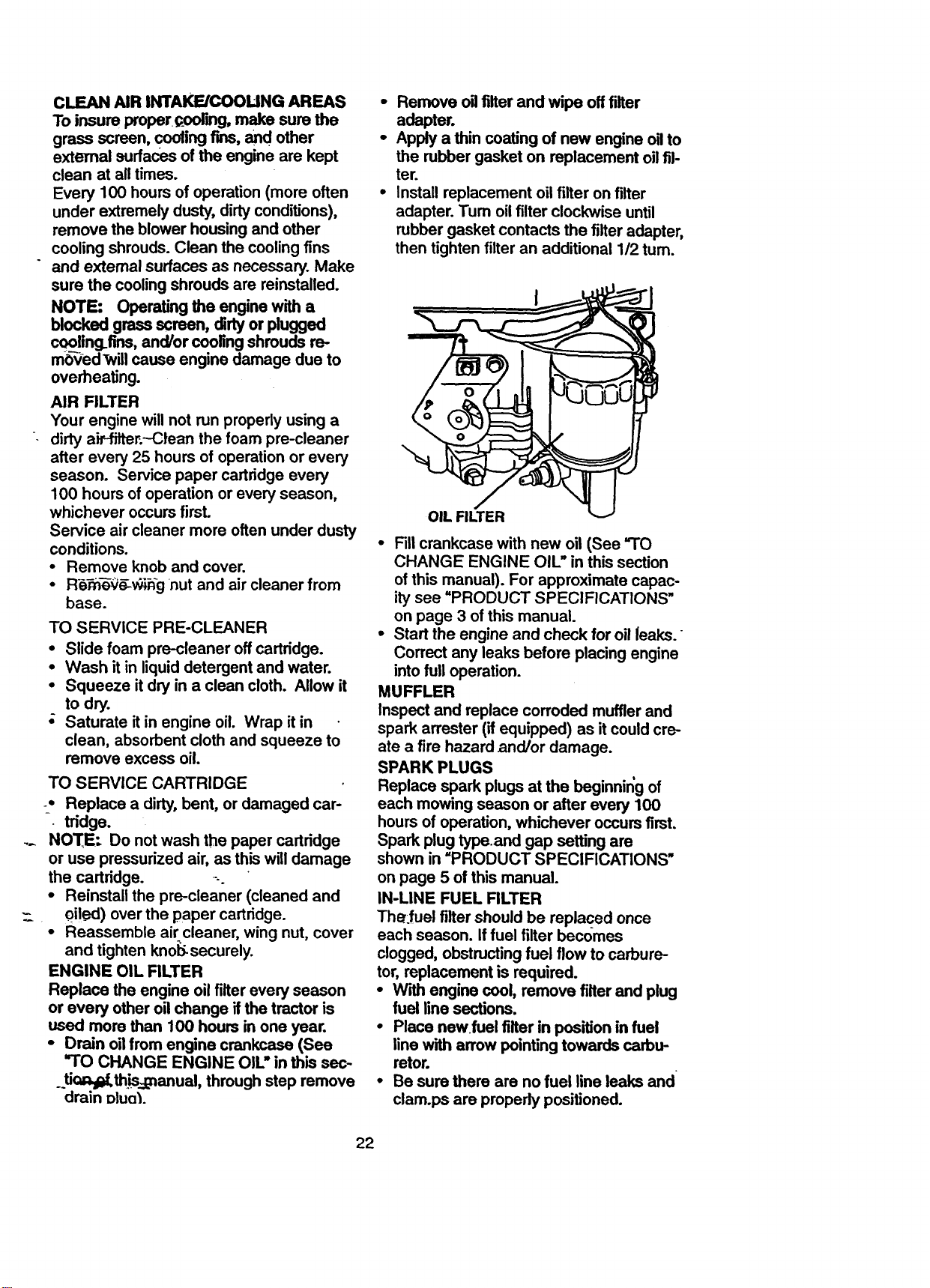
• Remove oil filter and wipe off filter
adapter.
• Apply a thin coating of new engine oilto
the rubber gasket on replacement oil fil-
ter.
• Install replacement oil filter on filter
adapter. Turn oil filter clockwise until
rubber gasket contacts the filter adapter,
then tighten filter an additional 1/2 turn.
OIL FILTER
• Fillcrankcase with new oil (See "TO
CHANGE ENGINE OIL" in thissection
ofthis manual). For approximate capac-
itysee =PRODUCT SPECIFICATIONS"
onpage 3 of this manual.
• Staff the engine and check for oil leaks.
Correct any leaks before placing engine
intofull operation.
MUFFLER
Inspect and replace corroded mufflerand
spark arrester (if equipped) as itcouldcre-
ate a fire hazard and/or damage.
SPARK PLUGS
Replace spark plugs at the beginnir_gof
each mowing season or after every 100
hoursof operation,whichever occursfirst,
Spark plugtype.and gap setting are
shown in•PRODUCT SPECIFICATIONS"
onpage 5 of this manual.
IN-LINE FUEL FILTER
The:fuel filtershould be replaced once
each season. If fuel filter becomes
clogged, obstructingfuel flow to carbure-
tor,replacement is required.
• With engine cool, remove filter and plug
fuel line sections.
• Place new fuel filter in positionin fuel
linewith arrow pointingtowards carbu-
retor.
• Be sure there are no fuel line leaks and
clam.ps are properly positioned.
22
3LEANING
Clean engine, battery,seat, finish, etc.
of all foreign matter.
• Keep finishedsurfaces and wheels free
ofall gasoline, oil, etc.
• Protect paintedsurfaces with automo-
tivetype wax.
We do not recommend using a garden
hose to clean your tractor unlessthe elec-
tricalsystem, muffler,air filter and carbure-
torare covered to keep water out. Water
in engine can resultin a shortened engine
life.
4kCAUTION: Before performingany service oradjustments:
• Depress clutch/brake pedal fully and set parkingbrake.
• Place motioncontrollever in neutral(N) position.
• Place attachment clutchin "DISENGAGED" position.
;• Turn ignition key-"OFF" and remove key.
• Make sure the blades and all moving parts have completelystopped.
• Disconnect spark plugwire from spark plugand place wirewhere itcannot come
in contact with plug.
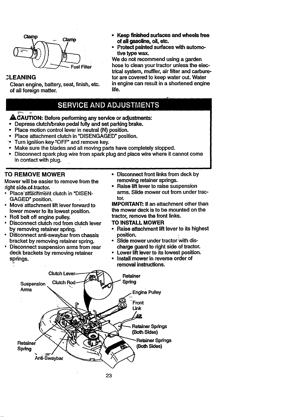
TO REMOVE MOWER
Mower will be easier to remove from the
rightside-of-tractor.
, Place-a-tt'_elTm=eritclutchin "DISEN-
GAGED" position.
• Move" attachment lift lever forward to
lower mower to its lowest position.
• Roll belt off engine pulley.
• Disconnect clutch rod from clutchlever
by removing retainer spring.
• Di_connect anti-swaybar from chassis
bracket by removing retainer spring.
• Disconnect suspension arms from rear
deck brackets by removing retainer
springs.
• Disconnectfront linksfrom deck by
removingretainer springs.
• Raise liftlever to raise suspension
arms. Slide mower out from under trac-
tor.
IMPORTANT: If an attachment other than
the mowerdeck isto be mounted on the
tractor,remove the front links.
TO INSTALL MOWER
• Raise attachment liftlever to its highest
position.
• Slide mower under tractor with dis-
charge guard to fight side of tractor.
• Lowerliftlever to its lowest position.
• Installmower in reverse order of
removalinstructions.
Suspension
Arms
Clutch
Clutch
Retainer
Spring
'Front
Unk
Retainer
Spring
AntJ-Swaybar
Retainer Springs
(BothSkies)
Springs
(BothSkies)
23
TO LEVEL MowER HOUSING
Adjust the mowe¢.wh,e tractor is parked
on level ground or drivewa_ Make sure
tireS_repropeiJy inflated (See "PROD-
UCT SPECIFICATIONS'). Iftires are
over or underinflated, you will not properly
adjust your mower.
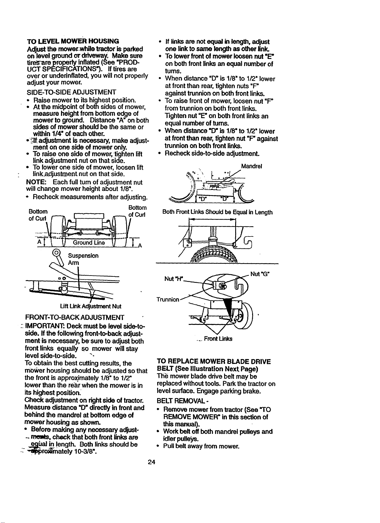
SIDE-TO-SiDE ADJUSTMENT
• Raise mower to its highest position.
• At the midpoint of both sides of mower,
measure height from bottom edge of
mower to ground. Distance "A" on both
sides of mower should be the same or
within 1/4" ofeach other.
• i:__adjustment is necessary, make adjust-
ment on one side of mower only.
• To raise one side of mower, tighten lift
link adjustment nut on that Side.
• To lower one side of mower, loosen lift
link_adjustment nut on that side.
NOTE: Each full turn of adjustment nut
will change mower height about 1/8".
• Recheck measurements after adjusting.
Bottom Bottom
of CudI_ f Cud
Suspension
Arm
Uft Unk AdjustmentNut
FRONT-TO-BACK ADJUSTMENT
: IMPORTANT: Deck must be level side-to-
side. If the following front-to-back adjust-
ment-is necessary, be=sure to adjust both
front links equally so mower will stay
level side-to-side. --
To obtain the best cutting results, the
mOwer housing Should be adjusted so that
the front is approximately 1/8" to 1/2"
lower than the rdar when the mower is in
its highest position.
Check adjustment on right side of tractor.
Measure distance "D" directly in front and
behind the mandrel at bottom edge of
mower housing as shown.
• Before making any necessary adjust-
-. rne=_, check that both front links are
_al in length. Both links should be
- "-mppro_mately 10-3/8".
• If links are not equal in length, adjust
one link to same length as other link.
• To lower front of mower loosen nut "E"
on both front links an equal number of
turns.
• When distance "D" is 1/8" to 1/2" lower
at front than rear, tighten nuts =_
against trunnion on both front links.
• To raise front of mower, loosen nut =F"
from trunnion on both front links.
Tighten nut "E" on both front links an
equal number of turns.
• When distance '1:)"is 1/8" to 1/2" lower
at front than rear, tighten nut "F" against
trunnion on both front links.
• Recheck side-to-side adjustment.
24
Mandrel
_|-u -u |
Both FrontLinks Should be Equalin Length
Nut "H"
"G"
Trunnion
... Front Unks
TO REPLACE MOWER BLADE DRIVE
BELT (See Illustration Next Page)
The mower blade drive belt may be
replaced without tools. Park the tractor on
level surface. Engage parking brake.
BELT REMOVAL-
• Remove mower from tractor (See "TO
REMOVE MOWER" in this section of
this manual).
• Work belt off both mandrel pulleys and
idler pulleys.
• Pull belt away from mower.
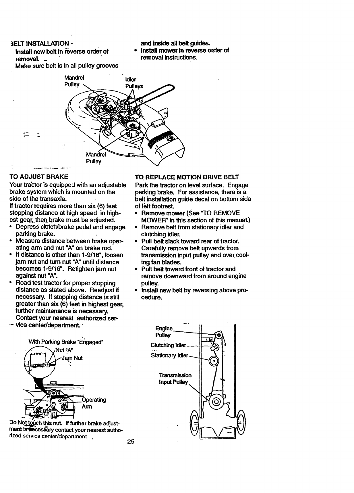
3ELTINSTALLATION -
Install new belt inreverse order of
remevaL _
Make sure belt is in all pulleygrooves
Mandrel
Pulley
and inside all belt guides.
• Install mower in reverse order of
removal instructions.
Idler
Mandrel
Pulley
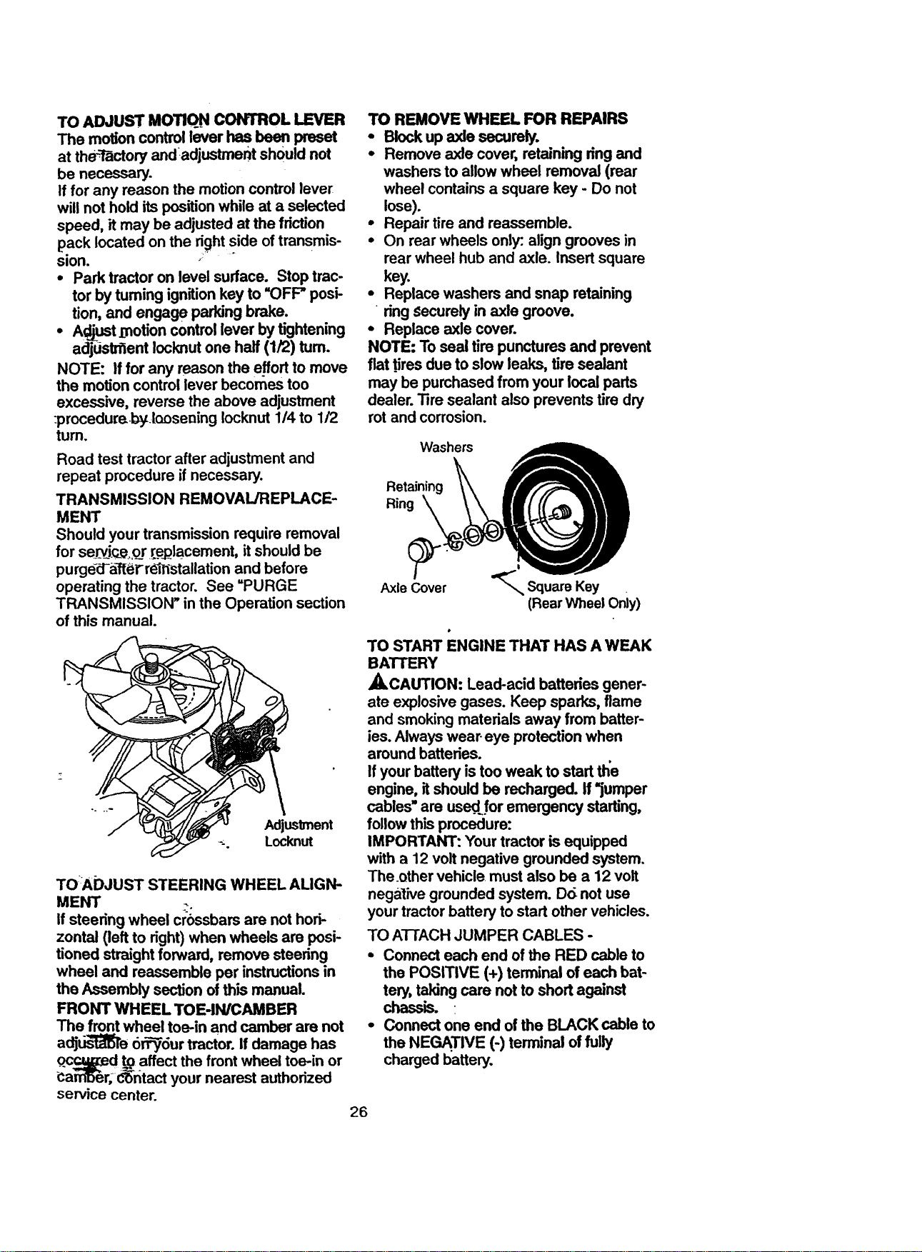
TO ADJUST BRAKE
Your tractor is equipped with an adjustable
brake system which is mounted on the
side of the transaxle.
If tractor requires more than six (6) feet
stopping distance at high speed in high-
est ge_r,_the_bJ:ake must be adjusted.
• DepresS--clotcWbrake pedal and engage
parking brake.
• Measure distance between brake oper-
ating arm and nut •A • on brake rod.
• If distance is other than 1-9/16", loosen
jam nut and turn nut •A" until distance
becomes 1-9/16 •. Retighten jam nut
against nut •A•.
• Road test tractor for proper stopping
distance as stated above. Readjust if
necessary. If stopping distance is still
greater than six (6) feet in highest gear,
further maintenance is necessary.
Contact your nearest authorized ser-
vice center/depadment
With Parking Brake =Engaged"
ut'A"
Arm
Do Not l this nut. Iffurther brake adjust-
me_ _"*
contactyournearestautho-
rizedservicecenterldepartment
25
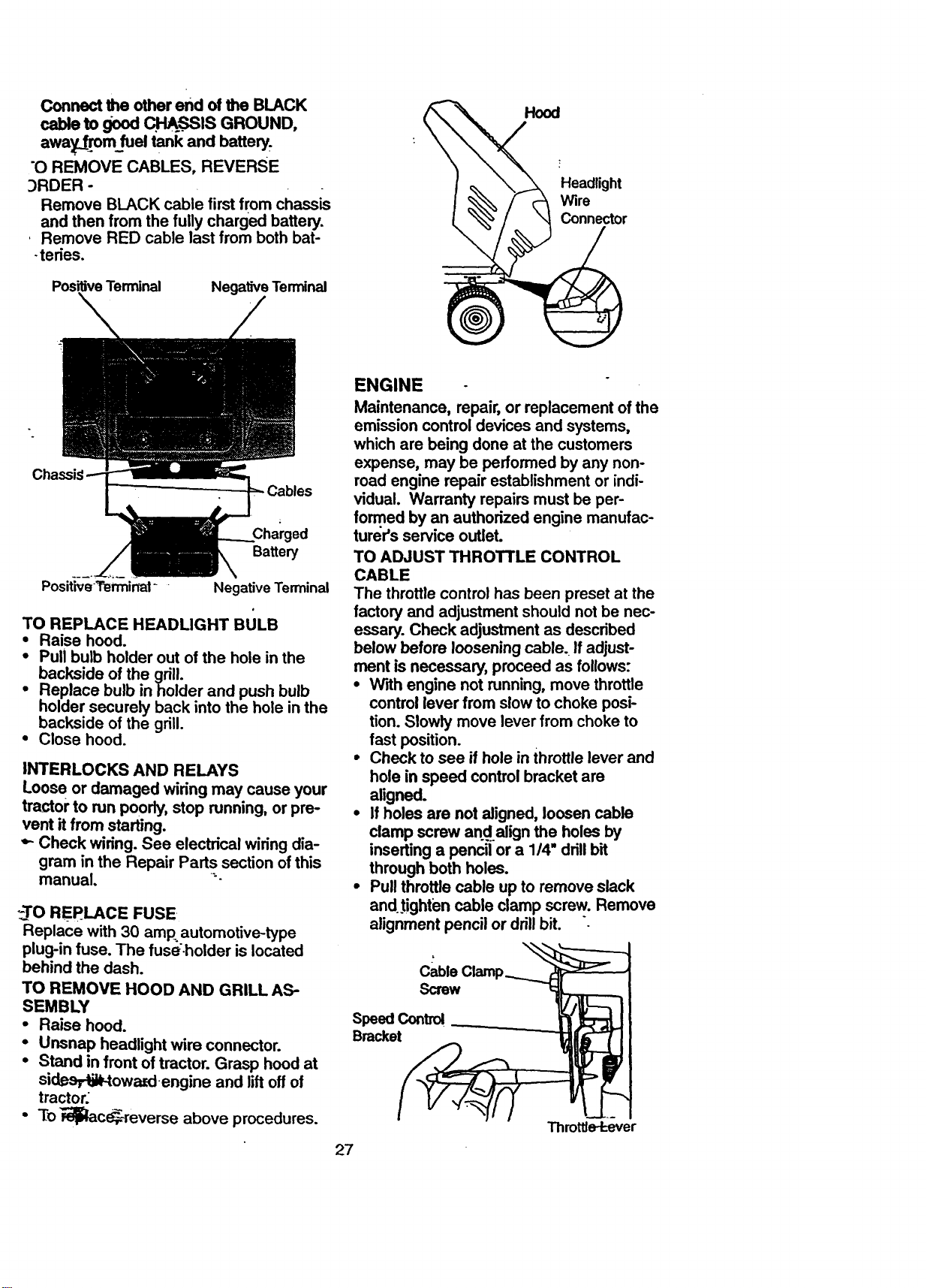
TO. REPLACE MOTION DRIVE BELT
Park the tractor on level surface. Engage
parking brake. For assistance, there is a
belt installation guide decal on bottomside
of I_ftfootrest.
• Remove mower (See "TO REMOVE
MOWER • inthis section of this manual.)
• Remove belt from stationaryidler and
clutchingidler.
• Pull belt slacktoward rear oftractor.
Carefully remove belt upwardsfrom
transmissioninput pulleyand over.cool-
ing fan blades.
• Pull belt toward front oftractor and
remove downwardfrom around engine
pulley.
• Install new belt by reversingabove pro-
cedure.
"4"
Engine
Pulley
ClutchingIdler
.o.
StationaryIdler-_.
Transmission
Input Pulley_
--,.-_0 ¸
TO ADJUST MO11_ONCONTROL LEVER
The motion control lever has been preset
at the:'f_ctory andadjustment should not
be necessary.
If for any reason the motioncontrollever
willnot hold its positionwhile at a selected
speed, it may be adjusted at the friction
pack located on the rightside oftransmis-
sion. "°
• Park tractor onlevel surface. Stop trac-
tor by tuming ignitionkey to "OFF" posi-
tion, and engage parkingbrake.
• Adjustmotion controllever by tightening
adjustn_entIocknutone half (1/2) tum.
NOTE: Iffor any reason the effortto move
the motioncontrollever becon_estoo
excessive, reverse the above adjustment
:procedureby IcLoseningIocknut114to 112
turn.
Road test tractor after adjustment and
repeat procedure if necessary,
TRANSMISSION REMOVAL/REPLACE-
MENT
Should your transmission require removal
for serv.ic_Q,o_rLep_lacement, it should be
purge-d-a_br-re-lr_stallation and before
operating the tractor. See =PURGE
TRANSMISSION" in the Operation section
of this manual.
Adjustment
Locknut
TOADJUST STEERING WHEEL ALIGN-.
MENT _.
If steering wheel crossbars are not hori-
zontal (left to right) when wheels are posi-
tioned straight forward, remove steering
wheel and reassemble per instructions in
the Assembly section of this manual.
FRONT WHEEL TOE-IN/CAMBER
The front wheel toe-in and camber are not
adjd.s"_'_e 6_6ur tractor. If damage has
o.c_d _ affect the front wheel toe-in or
_amlSer, C_ntact your nearest authorized
service center.
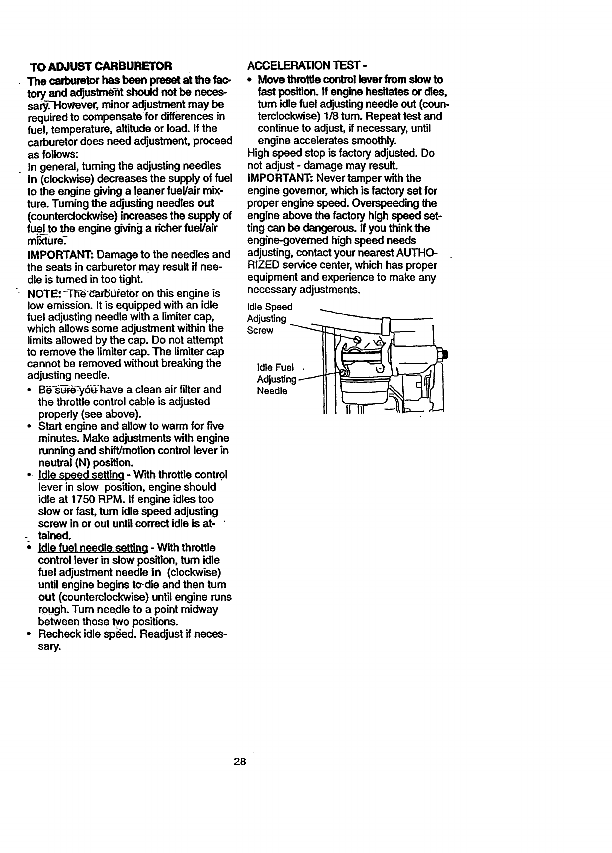
TO REMOVE WHEEL FOR REPAIRS
• Block up axle securely.
• Remove axle cover, retaining ring and
washers to allow wheel removal (rear
wheel contains a square key - Do not
lose).
• Repair tire and reassemble.
• On rear wheels only:,align grooves in
rear wheel hub and axle. Insert square
key.
• Replace washers and snap retaining
• ring Securely in axle groove.
• Replace axle cover.
NOTE: To seal tire punctures and prevent
fiat tires due to slow leaks, tire sealant
may be purchased from your local parts
dealer. "l]re sealant also prevents tire dry
rot and corrosion.
Washers
Ring k
Axle Cover
I
"_ Square Key
(Rear Wheel Only)
TO START ENGINE THAT HAS A WEAK
BATi'ERY
_CAUTION: Lead-acid batteries gener-
ate explosive gases. Keep sparks, flame
and smoking materials away from batter-
ies. Always wear-eye protection when
around batteries.
If your battery is too weak to start the
engine, it should be recharged. If _jumper
cables" are useC.for emergency starting,
follow this procedure:
IMPORTANT: Your tractor is equipped
with a 12 volt negative grounded system.
The other vehicle must also be a 12 volt
negative grounded system. D6 not use
your tractor battery to start other vehicles.
TO ATTACH JUMPER CABLES -
• Connect each end of the RED cable to
the POSITIVE (+) terminal of each bat-
tery, taking care not to short against
chassis.
• Connect one end of the BLACK cable to
the NEGATIVE (-) terminal of fully
charged battery.
26
Connecttheotherend of the BLACK
cable to good CHASSIS GROUND,
away_from fuel tank and battery..
"O REMOVE CABLES, REVERSE
:)RDER -
Remove BLACK cable first from chassis
and then from the fully charged battery.
Remove RED cable last from both bat-
-teries.
PositiveTerminal
Negative Terminal
Headlight
Wire
Connector
ed
Battery
PositiveTerminat- Negative Terminal
TO REPLACE HEADLIGHT BULB
• Raise hood.
• Pull bulb holder out of the hole in the
backside of the grill.
• Replace bulb inholder and push bulb
holder securely back into the hole in the
backside of the grill.
• Close hood.
INTERLOCKS AND RELAYS
Loose or damaged wiring may cause your
tractor to run poorly, stop running, or pre-
vent it from starting.
t- Check wiring. See electrical wiring dia-
gram in the Repair Parts section of this
manual, "-
_TO REPLACE FUSE
Replace with 30 amp..,automotive-type
plug-in fuse. The fuse-holder is located
behind the dash.
TO REMOVE HOOD AND GRILL AS-
SEMBLY
• Raise hood.
• Unsnap headlight wire connector.
• Stand in front of tractor. Grasp hood at
sid_sr-tJb-towa_d engine and lift off of
tractor;
• To ]_ac_.reverse above procedures.
ENGINE
Maintenance, repair, or replacement ofthe
emission controldevices and systems,
which are being done at the customers
expense, may be performed by any non-
road engine repair establishmentor indi-
vidual. Warranty repairs must be per-
form.ed by an authorized engine manufac-
turer's service outlet.
TO ADJUST THROTTLE CONTROL
CABLE
The throttlecontrol has been presetat the
factory and adjustmentshould not be nec-
essary. Check adjustment as described
below before looseningcable. If adjust-
ment is necessary, proceed as follows:
• W'_hengine not running,move throttle
controllever from slow to choke posi-
tion.Slowly move lever from choketo
fast position.
• Check to see if hole inthrottlelever and
hole in speed controlbracket are
aligned.
• If holes are not aligned, loosen cable
clamp screw an..d.alignthe holesby
insertinga pencil or a 1/4" drillbit
throughboth holes.
• Pullthrottle cable upto remove slack
and.tighten cable clamp screw. Remove
alignmentpencil or drillbit.
Cable
Screw
Speed Control
Bracket
27
Throttfe-Eever
TO ADJUST CARBURETOR
The carburetor has been preset at the fac-
tory and adjjustme_tshould not be neces-
sary.--However,minor adjustment may be
required to compensate for differences in
fuel, temperature, altitude or load: If the
carburetor does need adjustment, proceed
as follows:
In general, turningthe adjusting needles
in (clockwise) decreases the supply of fuel
to the engine givinga leaner fueVair mix-
ture. Turningthe adjusting needles out
(counterclockwise)increases the supplyof
fuelto the engine givinga richerfuel/air
mFxt_Jre_
IMPORTANT: Damage to the needles and
the seats in carburetor may result ifnee-
dle isturned in too tight.
NOTE:-Tri_'carbO_etOr onthis engine is
low emission. It is equipped with an idle
fuel adjusting needle with a limiter cap,
which allows some adjustment within the
limitsallowed by the cap. Do notattempt
to remove the limitercap. The limitercap
cannot be removed without breaking the
adjusting needle.
• B_--SrJ-reT-y_:d-havea clean air filter and
the throttle control cable is adjusted
properly (see above).
- Start engine and allow to warm forfive
minutes. Make adjustments with engine
running and shift/motion controllever in
neutral (N) position.
• Idle speed settina - With throttlecontr.ol
lever in slow position,engine should
idle at 1750 RPM. If engine idles too
slow or fast, tum idle speed adjusting
screw in or out untilcorrect idle is at- '
- tained.
• Idle fuel needle settina - With throttle
control lever in slow position,turn idle
fuel adjustment needle in (clockwise)
untilengine begins to-die and then tum
out (counterclockwise) until engine runs
rough. Turn needle to a point midway
between those _.twopositions.
• Recheck idle sp_ed. Readjust ifneces:
sary.
ACCELERA'I;ION TEST-
• Move throttle control lever from slow to
fast position. If engine hes'dates or dies,
turn idle fuel adjusting needle out (coun-
terclockwise) 1/8 tum. Repeat test and
continue to adjust, if necessary, until
engine accelerates smoothly.
High speed stop is factory adjusted. Do
not adjust - damage may result.
IMPORTANT: Never tamper with the
engine governor, which is factory set for
proper engine speed. Overspeeding the
engine above the factory high speed set-
ting can be dangerous. If you think the
engine-governed high speed needs
adjusting, contact your nearest AUTHO-
RIZED service center, which has proper
equipment and experience to make any
necessary adjustments.
Idle Speed
Adjusting
Screw
Idle Fuel
Needle
28
_mediately prepare your tractorfor stor-
age at the end of the season orifthe trac-
erwill not be used for 30 days or more.
ACAUTION: Never store the tractorwith
3asoline in the tank inside a building
where fumes may reach an open flame or
spark. Allow the engine to coolbefore stor-
ing in any enclosure.
TRACTOR
Remove mower from tractor for winter
storages.T_is will allow you to clean it thor-
oughly. Remove all dirt, grease, leaves,
etc. Store in a clean, dry area.
• Clean entire tractor (See =CLEANING"
• in the Majnt_enance- section of this man-
ual).
• Inspect and replace belts, if necessary
(See belt replacement instructions in the
Service and Adjustments section of this
manual).
• Lubricate as shown in the Maintenance
section of this manual.
• Be sureJha_t all _quts, bolts and screws
are s_:u-_eFy F'a-slened.Inspect moving
parts for damage, breakage and wear.
Replace if necessary.
• Touch up all rusted or chipped paint sur-
faces; sand lightly before painting.
BATTERY
• Fully charge the battery for storage.
• A_ter a period of time in storage, battery
may require recharging.
• To help prevent corrosion and power
leakage during long periods of storage,
battery cables should be disconnected
and battery cleaned thoroughly (see
=TO CLEAN BATI'ERY AND TERMI-
"" NALS" Fn the Maintenar_be section of
this manual).
• After cleaning, leave cal_Ies disconnect-
ed and place cables where they cannot
- come-in contact with battery terminals.
• If battery is removed, from tractor for
storage, do not store battery directly on
concrete or damp surfaces.
ENGINE
FUEL SYSTEM
IMPORTANT: It is important to prevent
gum deposits from forming in essential
fuel s.ystem-@arts_uch as carburetor, fuel
filter, fu__el'hose, or tank during storage.
Also, experience ind'mates that alcohol
blended fuels (called gasohol or using
ethanol or methanol) can attract moisture
which leads to separation and formation of
acids during storage. Acidic gas can dam-
age the fuel system of an engine while in
storage.
• Drain the fuel tank.
• Start the engine and let it run until the
fuel lines and carburetor are empty.
• Never use engine or carburetor cleaner
products in the fuel tank or permanent
damage may occur.
• Use fresh fuel next season.
NOTE: Fuel stabilizer is an acceptable
alternative in minimizing the formation of
fuel gum deposits during storage. Add sta-
bilizer to gasoline in fuel tank or storage
container. Always follow the mix ratio
found on stabilizer container. Run engine
at least 10 minutes after adding stabilizer
to allow the stabilizer to reach the carbure-
tor. Do not drain the gas tank and carbure-
tor if using fuel stabilizer.
ENGINE OIL
Drain oil (with enginewarm) and replace
with clean engine oil. (See "ENGINE-"in
the Maintenance section of this manual).
CYLINDER(S)
• Remove spark plug(s).
• Pour one ounce of oil through spark plug
hole(s) into cylinder(s).
• Turn ignition key to =START" position for
a few seconds to distribute oil.
• Replace with new spark plug(s).
OTHER
• Do not store gasoline from one season
to another.
• Replace your gasoline can if it starts to
rust. Rust and/or dirt in your gasoline will
cause problems.
• If possib!e, store your tractor indoors
and cover it to give protection from dust
and dirt.
• Cover your tractor with a suitable protec-
tive cover that does not retain moisture.
Do not use plastic. Plastic cannot
breathe, which allows condensation to
form and cause your tractor to rust.
IMPORTANT: Never cover tractor while
engine and exhaust areas are still warm.
29
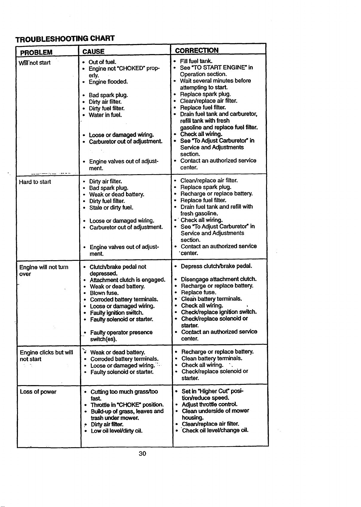
TROUBLESHOOTING CHART
PR.OBLEM
W_ll-notstart
Hard to start
Engine willnot turn
over
Engine clicksbut will
not start
_
Loss of power
CAUSE
- Outof fuel.
• Engine not'CHOKED" prop-
edy.
• Engine flooded.
• Bad sparkplug.
• Dirtyair filter.
• Dirtyfuelfilter.
• Water in fuel.
• Looseor damaged wiring.
• Carburetor out of adjustment.
• Engine valves out ofadjust-
ment.
• Dirty air filter.
• Badspark plug.
• Weak or dead battery.
• Dirty fuel filter.
• Stale or dirty fuel.
• Loose or damaged wiring.
• Carburetor out of adjustment.
• Enginevalves out of adjust-
ment.
• Clutch/brake pedal not
depressed.
• Attachment clutchisengaged.
• Weak or dead battery.
• Blownfuse.
• Corrodedbattery terminals.
• Loose or damaged wiring.
• Faultyignitions_tch.
• Faultysolenoidor starter.
• Faultyoperatorpresence
switch(es).
m
• Weak or dead battery.
• Corrodedbattery terminals.
• Looseor damaged wiring.::
• Faultysolenoidor starter.
• Cutting too much grass/too
fast.
• Throttlein "CHOKE" position.
• Build-upofgrass, leaves and
trashunder mower.
o Dirtyair filter.
• Lowoil level/dirtyoil.
CORRECTION
• Fill fuel tank.
• See "TO START ENGINE" in
Operation section.
• Wait several minutesbefore
attempting to start.
• Replace spark plug.
• Clean/replace air filter.
• Replace fuel filter.
• Drainfuel tank and carburetor,
refilltank with fresh
gasolineand replacefuel filter.
• Check all wiring.
• See "ToAdjust Carburetor"in
Service and Adjustments
section.
• Contact an authorized service
center.
• Clean/replace air filter.
• Replace spark plug.
• Recharge or replace battery.
• Replace fuel filter.
• Drain fuel tank and refillwith
fresh gasoline.
• Check all wiring.
• See "To Adjust Carburetor"in
Service and Adjustments
section
• Contact an authorized service
"center.
• Depress clutch/brake pedal.
• Disengage attachment clutch.
• Recharge or replace battery.
• Replace fuse.
• Clean battery terminals.
• Check all wiring.
• Check/replace ignitionswitch.
o Check/replace solenoid or
starter.
- Cootact an authorized sen/ice
center.
• Recharge or replace battery.
• Clean battery terminals.
• Check allwiring.
• Check/replace solenoidor
starter.
• Set in "HigherCut" posi-
Uon/reducaspeed.
• Adjustthrottle conlml.
• Clean undersideof mower
housing.
* .Clean/replace air filter.
• Check oil level/change oil.
3O
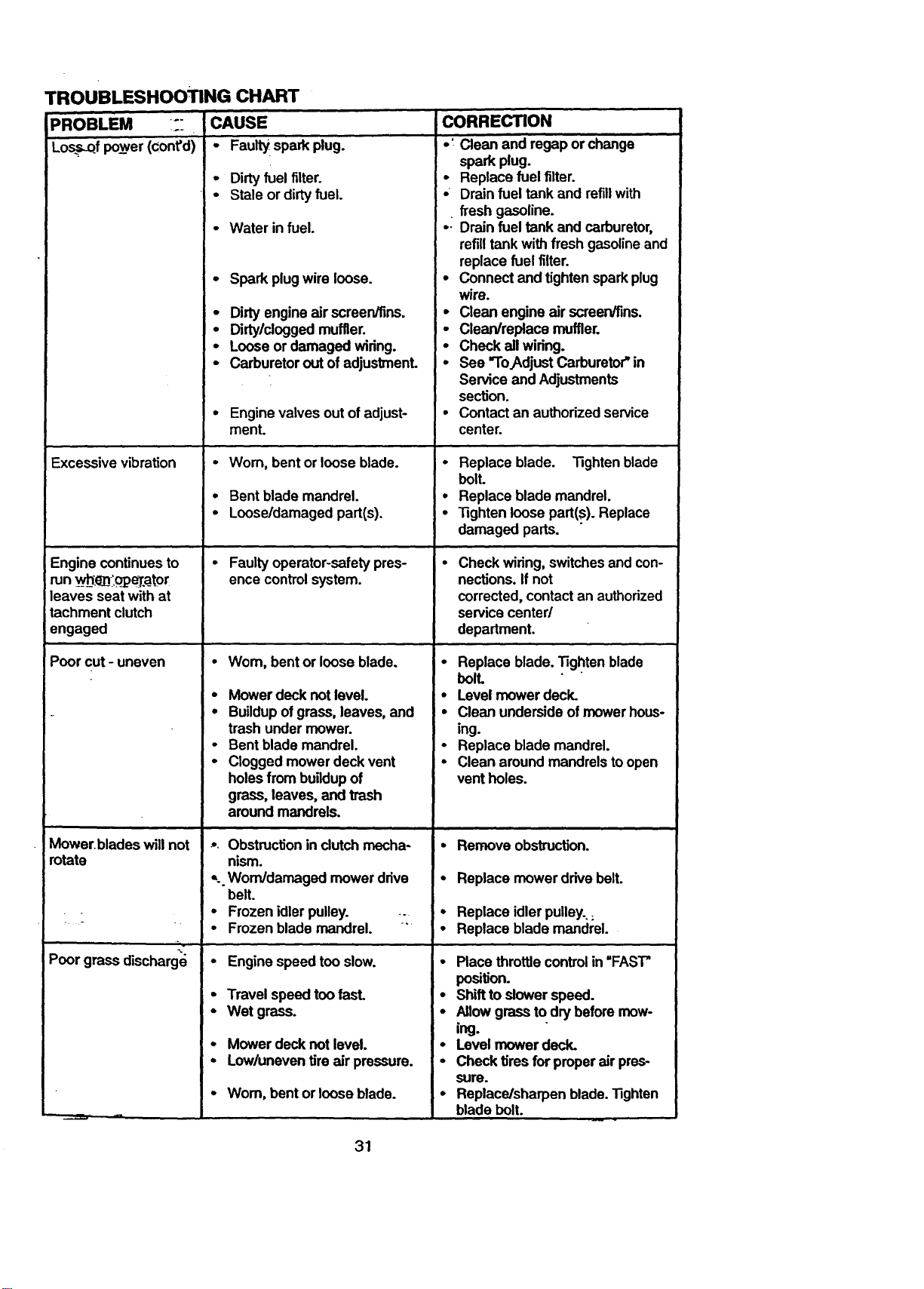
TROUBLESHOOTING CHART
PROBLEM i_'; CAUSE CORRECTION
• Faultyspark plug' -' Clean and regap or change
• Dirtyfuel filter.
• Stale or dirtyfuel.
• Water in fuel.
• Spark plugwire loose.
Lo.,s_s_.fpower (Cont'd)
Excessive vibration
Engine continuesto
runwb__]_0_a_tor
leaves seat with at
tachment clutch
engaged
Poor cut - uneven
Mower blades willnot
rotate
-.
Poor grass discharge
• Dirty engine air screen/fins.
• Dirty/dogged muffler.
• Loose or damaged wiring.
• Carburetorout of adjustment.
• Engine valves out of adjust-
ment.
• Worn, bent or loose blade.
• Bent blade mandrel.
• Loose/damaged part(s).
• Faultyoperator-safety pres-
ence controlsystem.
• Worn, bent or looseblade.
• Mower deck not level.
• Buildupof grass,leaves, and
trash under mower.
- Bent blade mandrel.
• Clogged mower deck vent
holesfrom buildupof
grass, leaves, and trash
around mandrels.
- Obstructionindutch mecha-
nism.
=..Worn/damaged mower drive
belt.
• Frozen idler pulley. .
• Frozen blade mandrel. "
• Engine speed too slow.
• Travel speed too fast.
• Wet grass.
- Mower deck not level.
• Low/uneventire air pressure.
• Worn, bent or looseblade.
spark plug.
• Replace fuel filter.
• Drain fuel tank and refillwith
• fresh gasoline.
•. Drain fuel tank and carburetor,
refilltank with fresh gasolineand
replacefuel filter.
• Connect and tighten spark plug
wire.
• Clean engine air screen/fins.
• Clean/replace muffler.
• Check all wiring.
• See "ToAdjust Carburetor"in
Service and Adjustments
section.
• Contact an authorizedservice
center.
• Replace blade. Tighten blade
bolt.
• Replace blade mandrel.
• Tighten loose part(s). Replace
damaged parts.
• Check wiring, switchesand con-
nections.If not
corrected, contact an authorized
service center/
department.
• Replace blade. Tighten blade
boll
• Level mower deck.
• Clean underside ofmower hous-
ing.
• Replace blade mandrel.
• Clean aroundmandrels toopen
vent holes.
• Remove obstruction.
• Replace mower ddve belt.
• Replace idler pulley.:
• Replace blade mandrel.
• Place throttlecontrolin "FAST"
position.
• Shin to slowerspeed.
• Allow grass to drybefore mow-
ing.
• Level mower deck.
• Check tires for properair pres-
sure.
• Replace/sharpen blade."13ghten
blade bolt.
31
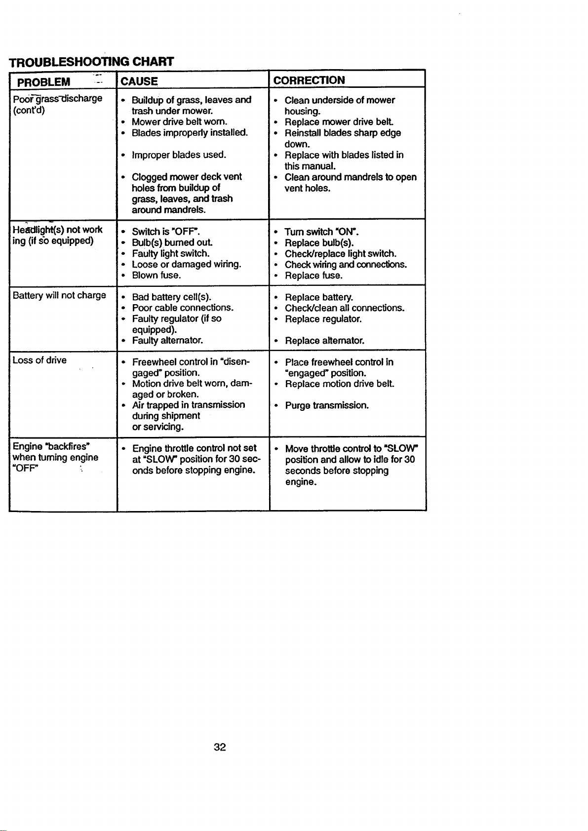
TROUBLESHOOTING CHART
CORRECTION
.p°
PROBLEM -- iCAUSE
Po0_-_rass-discharge • Buildupof grass,leaves and
(cont'd) trash under mower.
He_llight(s) not work
ing (if s'oequipped)
Battery willnot charge
Loss ofdrive
Engine "backfires"
when turning engine
"OFP :.
• Mower drive belt worn.
• Blades improperlyinstalled.
• Improperblades used.
Clogged mower deck vent
holesfrom buildupof
grass, leaves, and trash
around mandrels.
• Switch is'OFP.
• Bu!b(s)bumed ouL
• Faultylightswitch.
• Loose or damaged wiring.
• Blownfuse.
• Bad battery cell(s).
• Poorcable connections.
• Faultyregulator (ifso
equipped).
• Faultyalternator.
• Freewheel controlin=disen-
gaged"position.
• Motiondrive belt worn, dam-
aged or broken.
• Air trapped in transmission
duringshipment
or sewicing.
• Engine throttlecontrolnot set
at "SLOW" position for 30 sec-
ondsbefore stopping engine.
• Clean underside of mower
housing.
• Replace mower drivebelL
• Reinstallblades sharpedge
down.
• Replace with bladeslistedin
thismanual.
• Clean around mandrels toopen
vent holes.
• Turn switch"ON'.
• Replace bulb(s).
• Check/replace lightswitch.
• Check wiring andconnections.
• Replace fuse.
• Replace battery.
• Check/clean all connections.
• Replace regulator.
• Replace altemator.
• Place freewheel controlin
"engaged"position.
• Replace motion drive belt.
• Purge transmission.
Move throttle control to=SLOW"
position and allowto idlefor 30
seconds before stopping
engine.
32
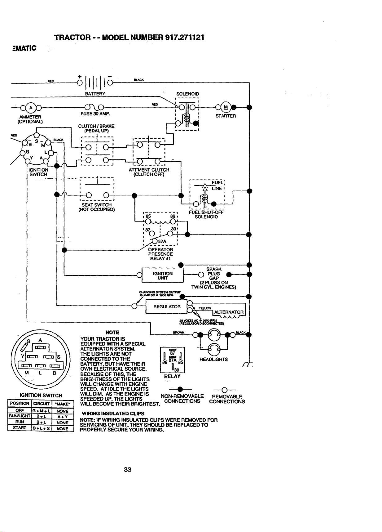
-iMATIC
TRACTOR - - MODEL NUMBER 917.271121
RED
BATrERY
SOLENOID
AMMETER
(OPTIONAl.)
FUSE30 AMP. I
STARTER
!
CLUTCHI BRAKE
I .- (PEDALUP)
,---t---- '....
I I I
u--g-o,: c-T , , ,
I I .... I I I I
NOTE
YOUR TRACTOR IS
EQUIPPED WITH A SPECIAL
ALTERNATOR SYSTEM.
THE LIGHTS ARE NOT
CONNECTED TO THE
BA'R'ERY, BUT HAVE THEIR
OWN ELECTRICAL SOURCE.
BECAUSE OF THIS, THE
BRIGHTNESS OF THE UGHTS
WILL CHANGE WITH ENGINE
SPEED. AT IDLE THE UGHTS
WILL DIM. AS THE ENGINE IS
SPEEDED UP, THE LIGHTS
WILL BECOME THEIR BRIGHTEST.
HEADUGHTS
/9
A
W
NON-REMOVABLE
CONNECTIONS
C>
REMOVABLE
CONNECTIONS
WIRING INSULATED CLIPS
NOTE: IF WIRING INSULATED CUPS WERE REMOVED FOR
SERVICING OF UNIT, THEY SHOULD BE REPLACED TO
PROPERLY SECURE YOUR WIRING.
3,3
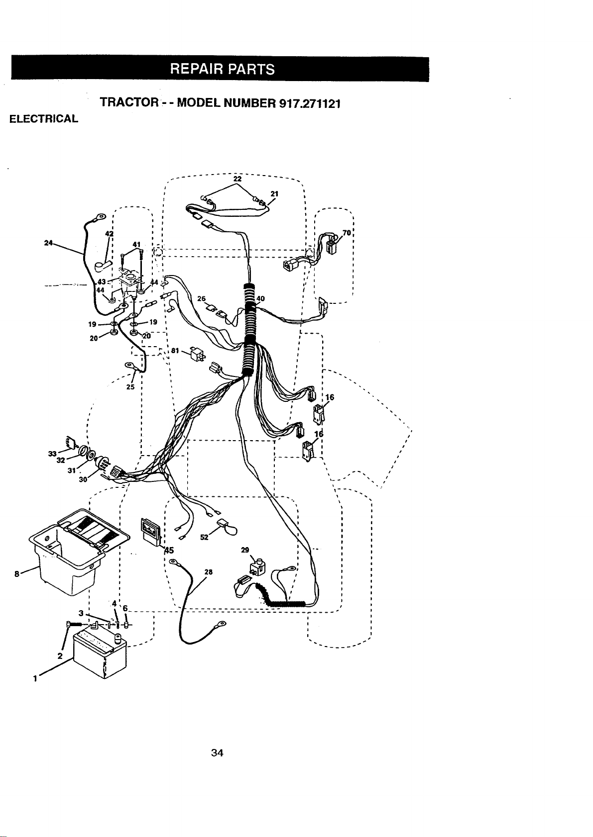
ELECTRICAL
TRACTOR. - MODEL NUMBER 917.271121
26
34

ELECTRICAL
TRACTOR - - MODEL NUMBER 917.271121
KEY PART
NO. NO. DESCRIPTION
1 163465 Battery12 Volt28 Amp
2 74760412 Bolt,HexHead 1/4-20uncx3/4
3 STD551025 Washer
4 STD551125 Washer
6 STD541025 Nut
8 156417 Case, BatteryMech Hinge
16. 161343 Switc_ InterlockN Opn/N Opn
19 STD551125 Washer, Lock
20 73350400 Nut, Hex,Jam 1/4-20 UNC
21 147430 Harness,Light Socket
(Includes4152J)
22 4152J Bulb, Light
24 4799J Cable, Battery,6 Gauge, Red, 11"
25 146147 Cable, Battery,6 Gauge, Red, W/16 Wire
26 108824X Fuse, 30 Amp
28 4207J Cable, Ground,6 Gauge. Black,12"
29 160784 Switch,PlungerNormalOp Olice
30 140301 Switch,Ignition
31 124211X Nut,Ign_on
32 141226 Cover,KeySwitch
33 109310)( Key,Ignition
40 161351 Harness.Ignition
41 71110408 Bolt,Hex Head, Fin. 1/4-20 x 1/2
42 131563 Cover,Terminal,Red
43 145673 Solenoid
44 73640400 Nut KepsBIk Hex 1/4-20 UNC
45 121433X AmmeterRectangular6Amp
52 141940 Protect_n WireLoop
70 140426 HarnessEngine
81 109748X Relay Asm.
NOTE: Allcomponentdimensionsgivenin U.S. inches
1inch = 25.4 mm
35
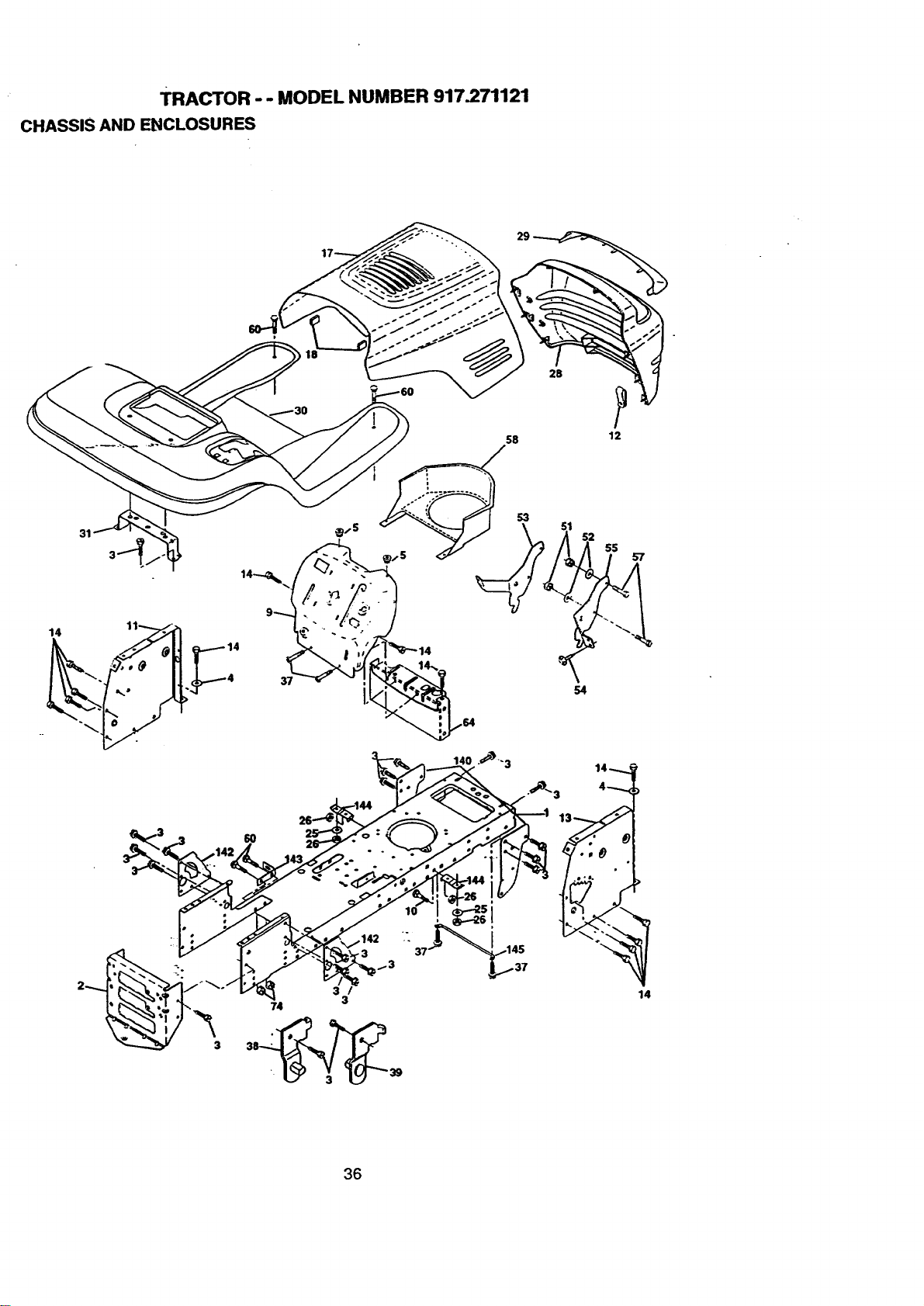
TRACTOR -- MODEL NUMBER 917.271121
CHASSIS AND ENCLOSURES
14
31
14_
4_
6O
3 /
3
74
38_ 39
13
.e-Oo
14
36

TRACTOR - - MODEL NUMBER 917.271121
CHASSIS AND ENCLOSURES
KEY PART
NO. NO. DESCRIPTION
1 160392 ChassisAssembly
2 140356 Drawbar
3 17490612 Screw,Thd. RolL 3/8-16x3/4
4 19131216 Washer 13/32 x3/4 x 16 Gauge
5 155272 BumperHood/Dash
9 161917X013 Dash
10 STD533710 Bolt,Carriage 3/8-16 x 1
11 155927 Panel,Dash,LH.
12 145660 Clip'13nnerrnanGdlleP/L
13 155936 Panel,Dash,R.H.
14 17490608 ScrewThdrol 3/8-16 x 1/2
17 144983X558 HoodAssembly
18 126938X BumperHood
25 19131312 Washer 13/32x13/16 x12 Gauge
26 STD541437 Nut
28 145198X558 Grillew/ClipsMS-558
29 155217 Lens,Grille
30 151287X558 Fend/FtrestPntSTLTN HLD 558
31 139976 Bracket,FenderSupport
37 17490508 ScrewThdrol 5/16-18 x 1/2Tyt
38 139886 PivotBracketAssembly,LH.
39 139887 PivotBracketAssembly,R.H.
51 73800400 Nut Lockw/Insert 1/4-20 UNC
52 19091416 Washer 9/32xT/Sx16Ga.
53 145201 BracketGn'llePickolfLH
54 161464 ScrewHexWshd 8-18x7/8
55 145202 BracketGrillePicko#RH
57 STD522507 Bolt,Rn Hex 1/4-20 UNC x .75
58 150127 DuctAir EnginePA.LT
60 72140606 Bolt RdhdSopk3/8-16 UNC x 3/4
64 154798 Dash LowerSTLT
74 73680600 Nut Crownlock3/8-16 UNC
140 158418 BracketSuspensionFront
142 156095 Plate RetnfomementSTLT
143 154966 BracketSwaybar_
144 154207 BracketPntFootrestSTLT
145 156524 RJodpivot Chassis/Hood
-- 5479J Plug,Button
NOTE?All componentdimensionsgiveninU.S. inches
1inch= 25.4 mm
37
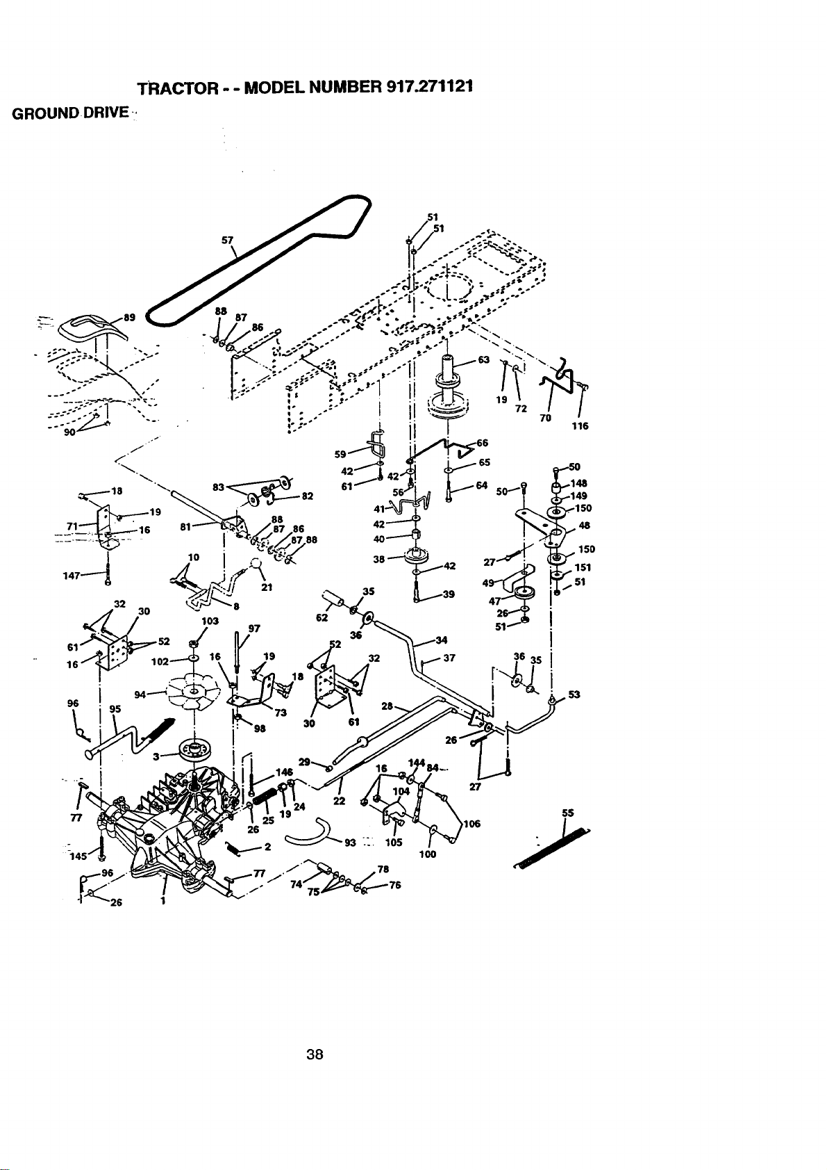
\
i
3_
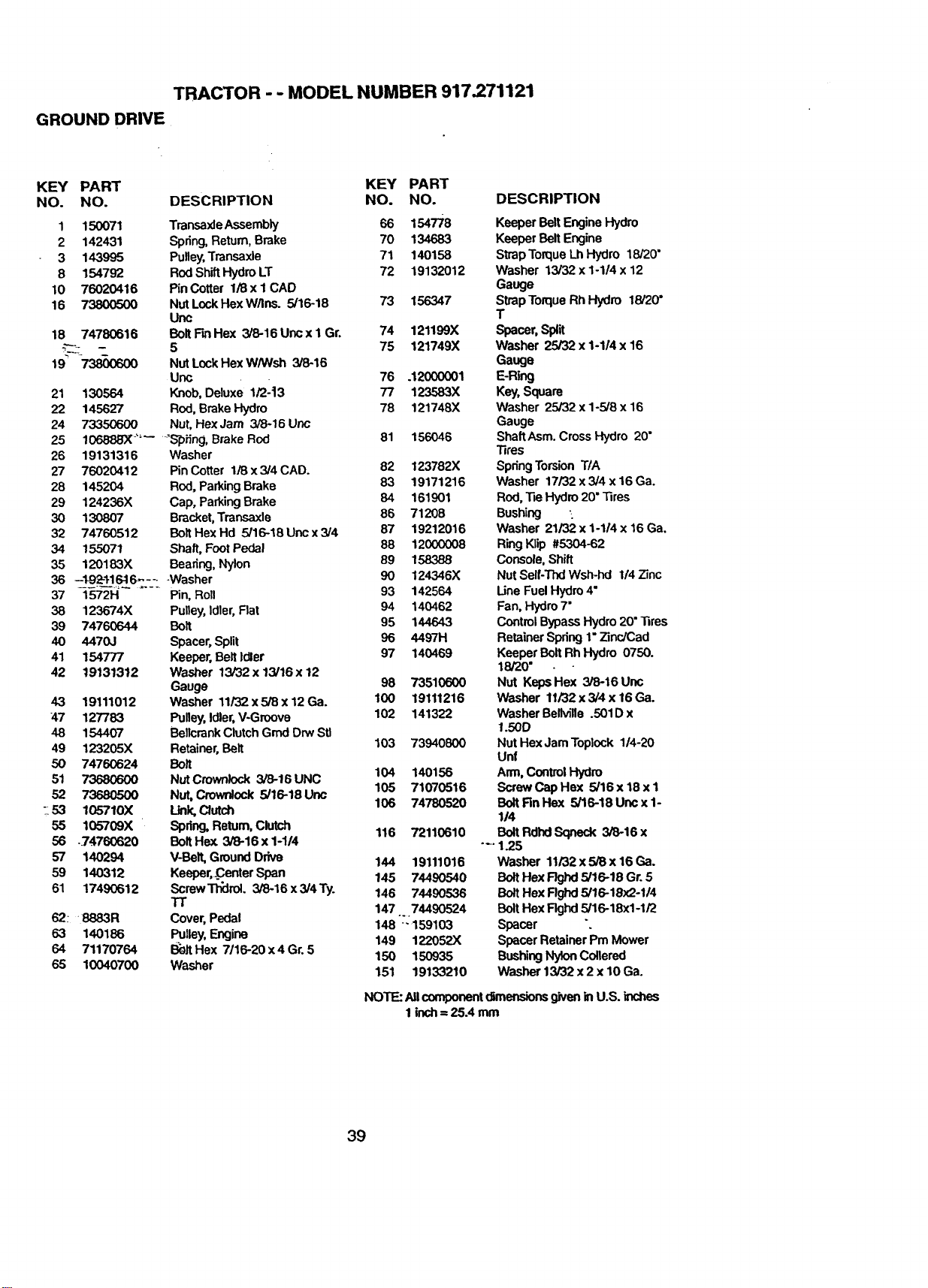
TRACTOR - - MODEL NUMBER 917.271121
GROUND DRIVE
KEY PART
NO. NO. DESCRIPTION
KEY PART
NO. NO.
1 150071 TransaxleAssembly 66 154718
2 142431 Spring,Return,Brake 70 134683
3 143995 Pulley,Transaxle 71 140158
8 154792 RodShift HydroLT 72 19132012
10 76020416 PinCotter 1/8 x I CAD
16 73800500 NutLockHexW/Ins. 5/16-18 73 156347
Unc
18 74780616 BoltRnHex 3/8-16Uncx1 Gro 74 121199X
-"-- - 5 75 121749X
19" -'/38_o00 NutLockHexW/Wsh 3/8-16
Unc 76 .12000001
21 130564 Knob,Deluxe 1/2-13 77 123583X
22 145627 Rod,Brake Hydro 78 121748X
24 73350600 Nut,HexJam 3/8-16 Uric
25 106888X ....... S'piing,BrakeRod 81 156046
26 19131316 Washer
27 76020412 PinCotter 1/8 x 3/4 CAD.
28 145204 ROd,ParkingBrake
29 124238X Cap, ParkingBrake
30 130807 Bracket,Transaxle
32 74760512 BoltHexHd 5/16-18Uncx3i4
34 155071 Shaft,Foot Pedal
35 120183X Bearing,Nylon
36 -__t._! 6-16---_-:-Washer
37 1572H Pin,Roll
38 123674X Pulley,Idler,Flat
39 74760644 Bolt
40 4470J Spacer,Split
41 154777 Keeper,BeltIdler
42 19131312 Washer 13/32 x 13/16 x 12
Gauge
43 19111012 Washer 11/32x5/8x12Ga.
47 127783 Pulley,Idler,V-Groove
48 154407 BellcrankClutchGradDrw Stl
49 123205X Retainer,Belt
50 74760624 Bolt
51 73680600 NutCrownlock 3/8-16UNC
52 73680500 Nut,Crownlock 5/16.18 Unc
53 105710X Link,Clutch
55 105709X Spdng, Return,Clutch
55 .74760620 Bolt Hex 3/8-16 x1-1/4
57 140294 V-Belt, GroundDrive
59 140312 Keeper,..CenterSpan
61 17490612 Screw'rh_rol. 3/8-16x3/4Ty.
TT
62: 8883R Cover,Pedal
63 140186 Pulley,Engine
64 71170764 BoltHex 7/16.20 x4 Gr.5
65 10040700 Washer
82 123782X
83 19171216
84 161901
86 71208
87 19212016
88 12000008
89 158388
90 124346X
93 142564
94 140462
95 144643
96 4497H
97 140469
98 7351060O
100 19111216
102 141322
103 73940800
104 140156
105 71070516
106 74780520
116 72110510
144 19111016
145 74490540
146 74490536
147 74490524
o..
148 '159103
149 122052X
150 150935
151 19133210
DESCRIPTION
Keeper BeltEngineHydro
Keeper BeltEngine
StrapTon:lue LhHydro 18/20"
Washer 13/32 x1-1/4 x 12
Gauge
StrapTorqueRhHydro 18/20"
T
Spacer.Sp_it
Washer 25/32 x 1-1/4 x 16
Gauge
E-R|ng
Key,Square
Washer 25/32 x 1-5/6 x 16
Gauge
ShaftAsm. CrossHydro 20"
Tires
SpringTorsionT/A
Washer 17/32 x3/4 x 16 Ga.
Rod,Re I-lydro20""13res
Bushing _.
Washer 21/32 x 1-1/4 x 16 Ga.
RingKlip #5304-62
Console, Shift
Nut Self-ThdWsh-hd 1/4Zinc
LineFuel Hydro4"
Fan, Hydro7"
ControlBypassHydro20"_res
RetainerSpring1" Zinc/Cad
Keeper Bolt RhHydro 0750.
18/20"
Nut KepsHex 3/8-16 Unc
Washer 11/32 x3/4 x 16Ga.
Washer Belhn'lle.501D x
1.50D
Nut HexJamToplock 114-20
Un|
Arm, ControlHydro
ScrewCap Hex 5/16x 18x 1
BoltRn Hex 5/16-18 Unc x 1-
114
BoltRdnd Sqneck 3/8-16 x
.... 1.25
Washer 11/32 x5/8 x 16 Ga.
BoltHex Rghd 5/16-18 Gr.5
BoltHex Rghd 5/16.18x2-1/4
BoltHex Flghd5/16-18x1-1/2
Spacer
SpacerRetainerPm Mower
BushingNylonCollered
Washer13/32 x 2 x 10 Ga.
NOTE: Allcomponentd=mensionsgiveninU.S. inches
1ir_h = 25.4 mm
39
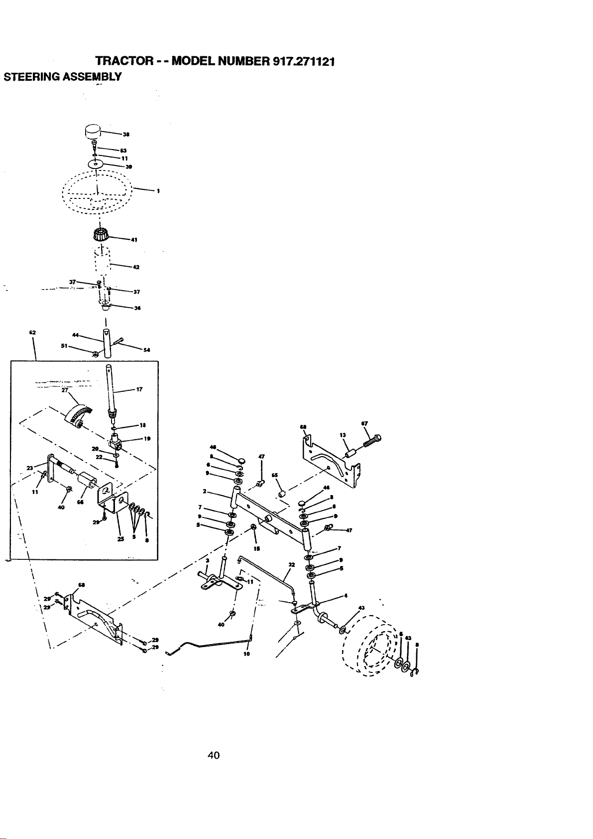
TRACTOR- - MODEL NUMBER 917.271121
STEERING ASSEMBLY
F.. I .
_°
1
$2 44
4O

TRACTOR - - MODEL NUMBER 917.271121
'TEERING ASSEMBLY
KEY PART
NO. NO. DESCRIPTION
1 139768
2 154427
3 156483
4 157473
5 6266H
6 121748X
7 19272016
8 12O00O29
9 3366R
10 156438
11 STD551137
13 154779
_15- 73901000
17 156546
18 57079
19 124035X
20 126684X
22 71200410
23 127501
25 154406
26 126847X
27 136874
28 19131416
29 17490612
30 STD561210
32 130465
36 155099
37 152927
38 139769
39 19133808
40 STD541537
41 100711L
42 145054
43 121749X
44 153720
46 121232X
47 6855M
51 STD541431
54 74780520
62 156594
63 STD523710
65 15_780
66 154404
67 74781044
68 154429
NOTE:
Steering Wheel
AxleAssemblySTMP DroppedSTL
Spindle Assembly,L.H.
SpindleAssembly,R.H,
Beadng,Race, Thrust,Hardened
Washer 25/32 x 1-5/8 x 16 Gauge
Washer 27/32 x 1-1/4 x 16 Gauge
Ring, Kiip
Bearing,SteeringColumn
DraglinkExtendedStamped
Washer,Lock
BeadngAxleSTLT/GT
Nut,Lock,Range 5/8-11UNC
ShaftAssembly,Steedng
Washer,Thrust .515x .750 x .033
Support,Shaft
Washer, Shim 1/4x 5/Bx .062
ScrewHex Socket 1/4-20x
PittmanShaftAssembly
Bracket,Steering
Bushing,Link,Drag
Gear,Sector
Washer 13/32 x7/8 x16 Gauge
Screw,Thd., Roll. 3/8-16 x 3/4
Pin
Rod,Tie
Bushing,Steering
Screw
Insert,SteeringWheel
Washer 13/32 x2-3/8 x 8 Gauge
GripcoNut
Adaptor,SteeringWheel
Boot,SteeringShaft
Washer 25/32 x 1-1/4x 16 Gauge
ExtensionShaftSteedng LR.LT
Cap. SpindSe
Fdting,Grease
Nut LockHex w/Ins. 5/16-18 UNC
BoltRn Hex 5/16-18 UNC x1-1/4
KitSteeringAsm Service
Bolt,FinHex 3/8-16 UNC x I Gr 5
SpacerAxle
BearingArm Pittman
Bolt,FinHex 5/8-11 UNC x 2-3/4
Axle,Brace
All componentdimensionsgiveninU.S. inches
1inch = 25.4 mm
41
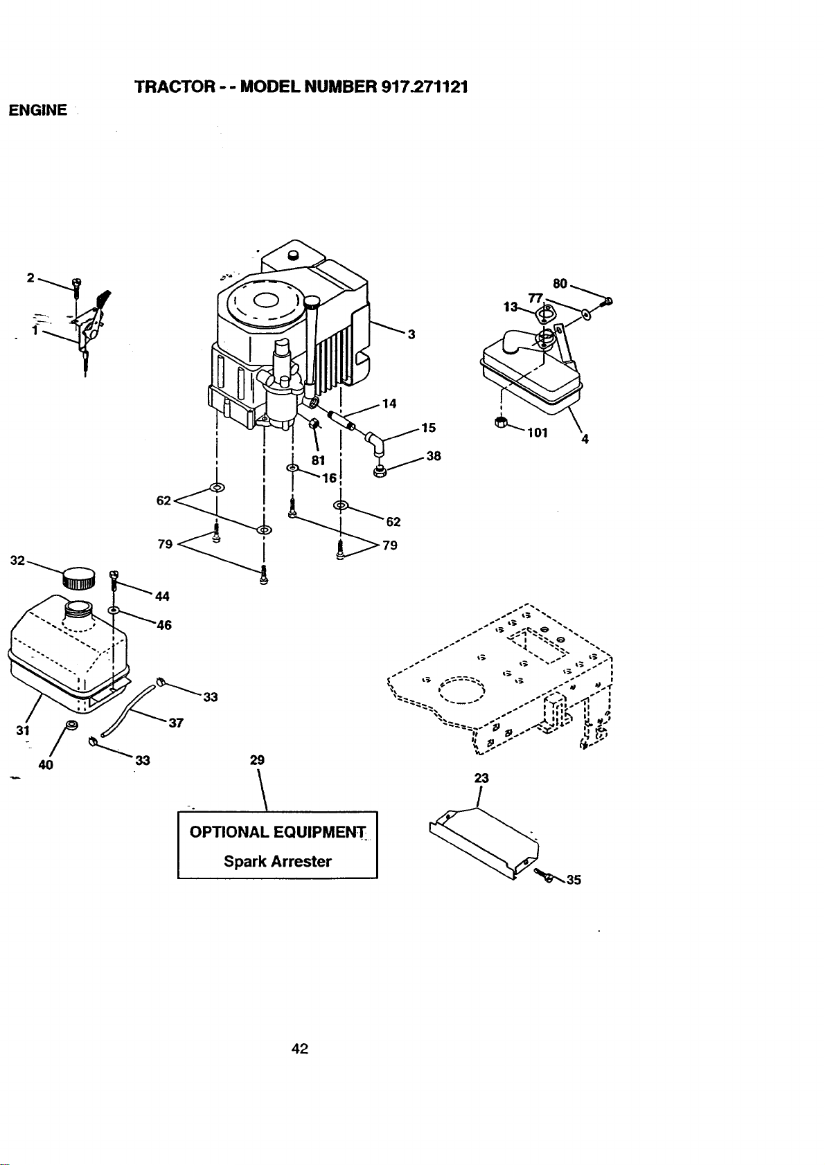
ENGINE"
TRACTOR - - MODEL NUMBER 917.271121
80
_" 101
4
33
33
29
w.
I OPTIONAL EQUIPMENT
I Spark Arrester
23
/
42
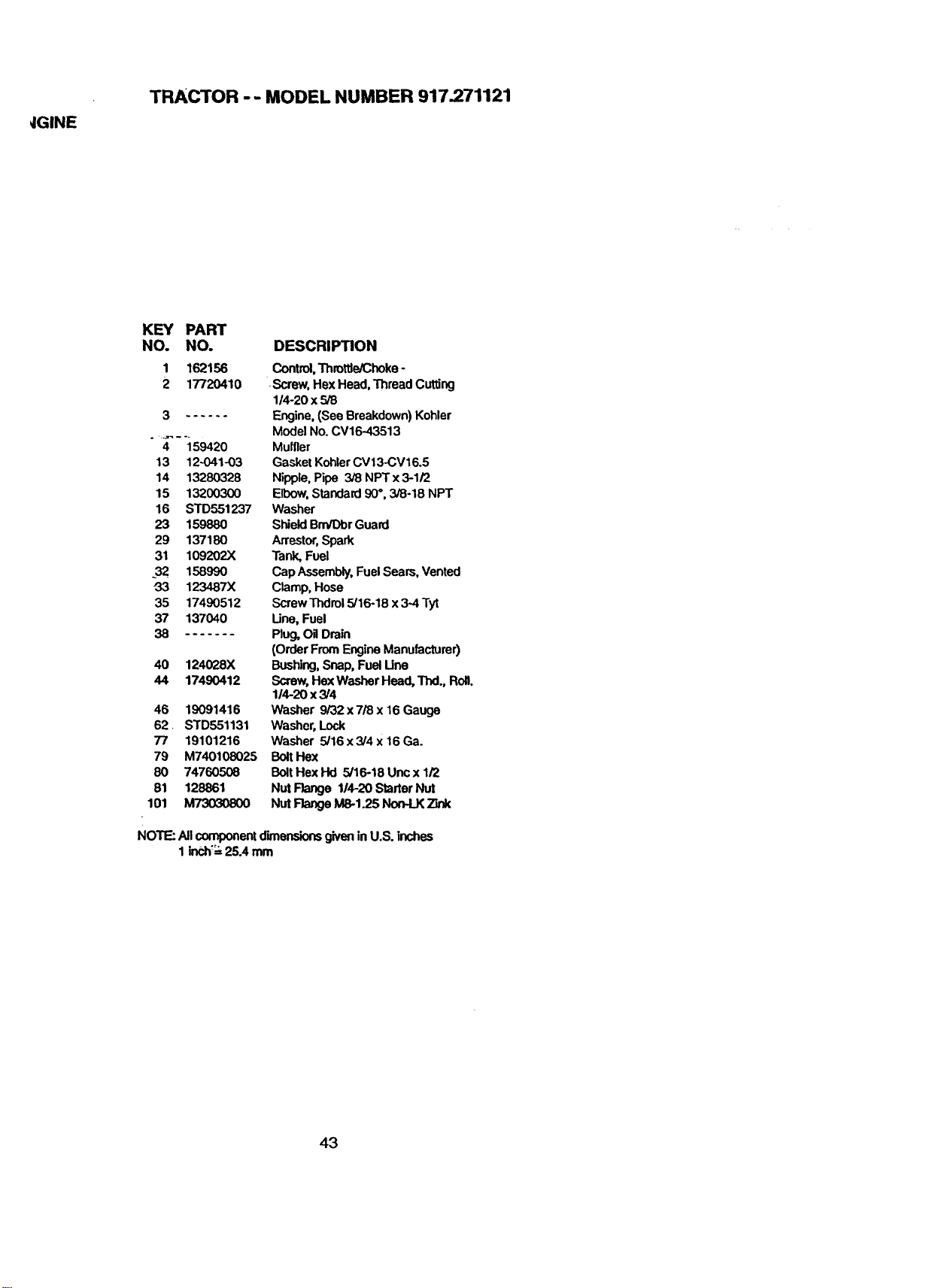
4GINE
TRACTOR -- MODEL NUMBER 917.271121
KEY PART
NO. NO. DESCRIPTION
1 162156 Control,Throttle/Choke-
2 17720410 .Screw, HexHead,Thread Cutting
1/4-20 x 5/8
3 ...... Engine,(See Breakdown)Kohler
Model No.CV16-43513
4 159420 Muffler
13 12-O41-03 GasketKohierCV13-CV16.5
14 13280328 Nipple,Pipe 3/8 NPT x 3-1/2
15 13200300 Elbow, Standard 90°, 3/8-18 NPT
16 STD551237 Washer
23 159880 Shield Brn/DbrGuard
29 137180 Arrestor,Spark
31 109202X Tank, Fuel
158990 Cap Assembly,Fuel Sears, Vented
33 123487X Clamp, Hose
35 17490512 ScrewThdrol 5/16-18 x 3-ATyt
37 137040 Une, Fuel
38 ....... Plug,OilDrain
(OrderFromEngineManufacturer)
40 124028X Bushing,Snap,Fuel Une
44 17490412 Sorew,HexWasherHead, TIxl., Roll.
1/4-20 x 3/4
46 19091416 Washer 9/32 x7/8 x 16 Gauge
62. STD551131 Washer,Lock
77 19101216 Washer 5/16 x3/4 x 16Ga.
79 M740108025 BoltFlex
80 74760508 BoltHex Hd 5/16-18 Unc x 1/2
81 128861 NutRange 114-20StarterNut
101 M73030800 Nut FlangeM8-1.25 Non-LKZink
NOTE: Allcomponentdimensionsgivenin U.S.inches
1 inch_:.;25.4 mm
43
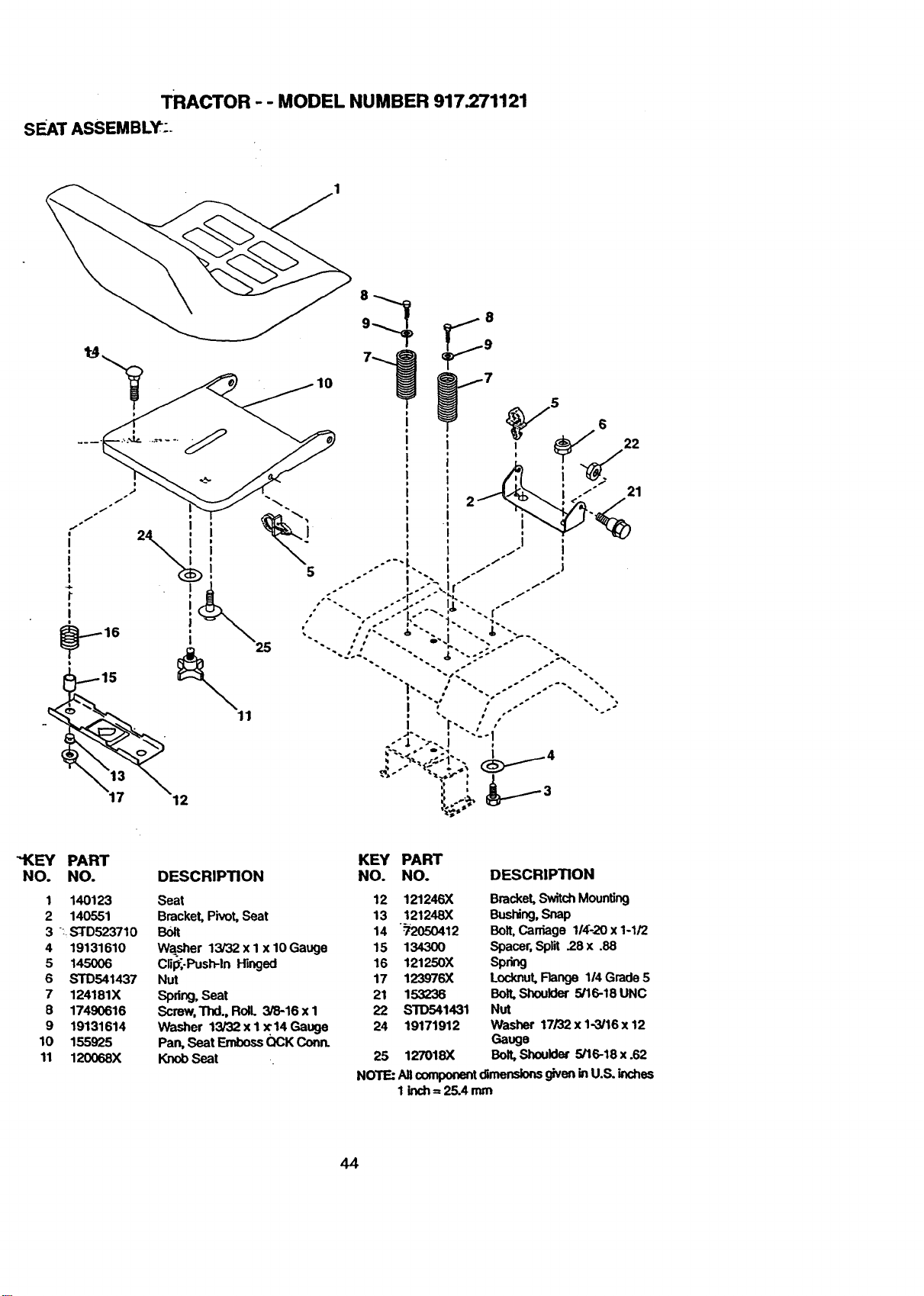
TRACTOR -- MODEL NUMBER 917.271121
SEAT ASSEMBLY;-
IL4,
5
NO.
1
2
3
4
5
6
7
8
9
10
11
PART
NO.
140123
140551
-_STD523710
19131610
145006
STD541437
124181X
17490616
19131614
155925
120068X
DESCRIPTION
Seat
Bracket,Pivot, Seat
B01t
Washer 13/32 x I x 10 Gauge
Clip_-Push-lnHinged
Nut
Spdng, Seat
Screw,Thd., RolL 3/8-16 x 1
Washer 13/32 x I _14 Gauge
Pan, Seat EmbossQCK Conn.
KnobSeat
KEY PART
NO. NO. DESCRIPTION
12 121246X Bracket,SwitchMounting
13 121248X Bushing,Snap
14 -72050412 Bolt,Carriage 114"-20x 1-1/2
15 134300 Spacer,Split 2.8x .88
16 121250X Spring
17 123976)( Locknut,Flange 1/4 Grade5
21 153236 Bolt,Shoulder 5/16-18UNC
22 STD541431 Nut
24 19171912 Washer 17/32xl-3/16x12
Gauge
25 127018X Bolt,Shoulder5II6-18 x.62
NOTE: Allcomponentdimensionsgivenin U.S.inches
1inch= 25.4 mm
44
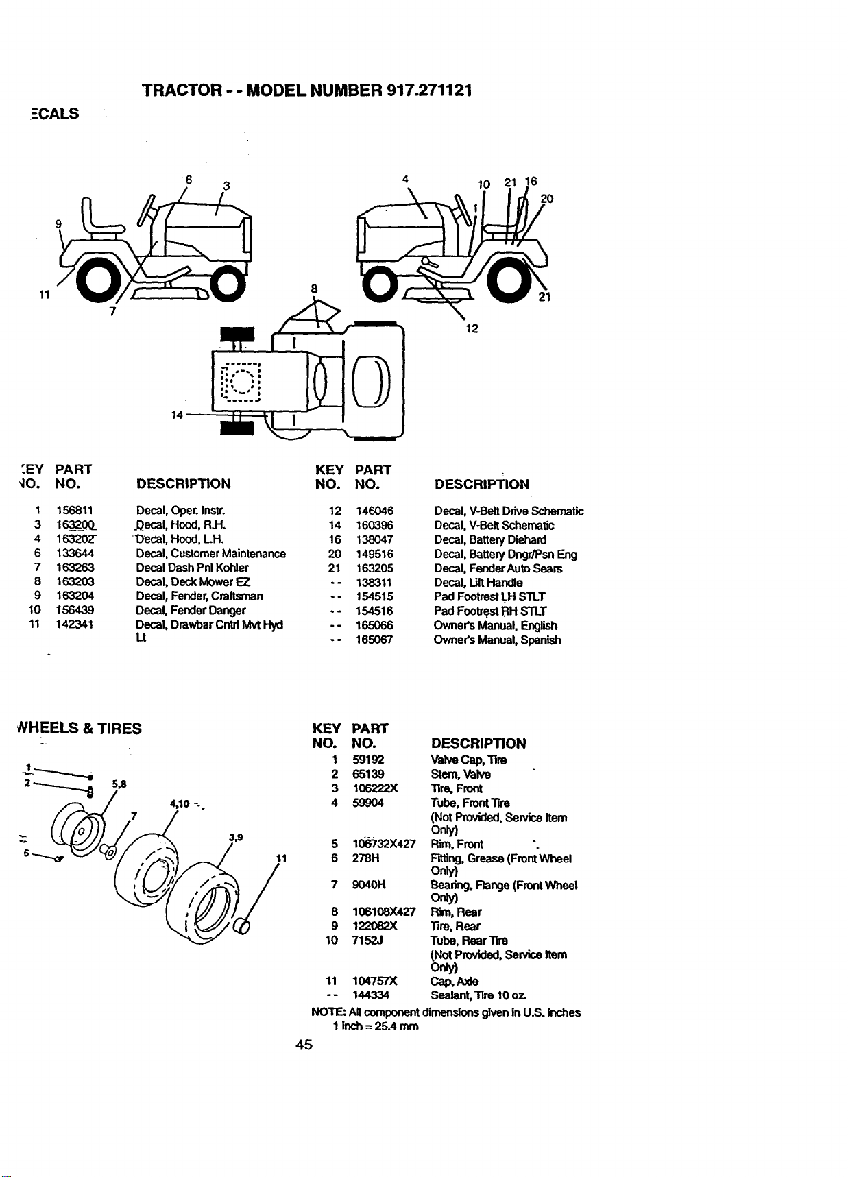
ECALS
TRACTOR - - MODEL NUMBER 917.271121
6
3
10
16
2O
11
12
21
".EY
qO.
PART
NO.
1 156811
3 1632(X}_
4 163202
6 133644
7 163263
8 163203
9 163204
10 156439
11 142341
DESCRIPTION
Decal,Oper.Instr.
_Decal,Hood,R.H.
Decal, Hood,LH.
Decal,CustomerMaintenance
Decal Dash Pnl Kohler
Decal Deck MowerEZ
Decal,Fender,Craltsman
Decal,FenderDanger
Decal,DrawbarCntrlMvt Hyd
Lt
KEY
NO.
PART
NO.
12 146046
14 160396
16 138047
20 149516
21 163205
-- 138311
-- 154515
-- 154516
-- 165066
- - 165067
DESCRIPTION
Decal,V-BeltDriveSchematic
Decal,V-BeltSchematic
Decal, BatteryDiehard
Decal,BatteryDngr/PsnEng
Decal,FanderAuto Sears
Decal, LiltHandle
Pad Footrest.LHSTLT
Pad Foob'estP,HSTLT
OwneCsManual,English
Owners Manual,Spanish
NHEELS & TIRES
11
KEY PART
NO. NO. DESCRIPTION
1 59192 Valve Cap, Tim
2 65139 Stern,Valve
3 106222X Tire, Front
4 59904 Tube, FrontTire
(NotProvided,ServiceItem
o_)
5 10b'732X427 Rim, Front
6 278H F'_ng, Grease (FmntWheel
Orgy)
7 9040H Bearing,Flange(FrontWheel
o_)
8 106108X427 Rim.Rear
9 122082X Tire, Rear
10 7152J Tube, RearTire
{NotProvided,SePAceItem
Ody)
11 104757X Cap, Axle
- - 144334 Sealant,Tire 10 oz.
NOTE: Allcomponentdimensionsgivenin U.S. inches
1inch = 25.4 mm
45
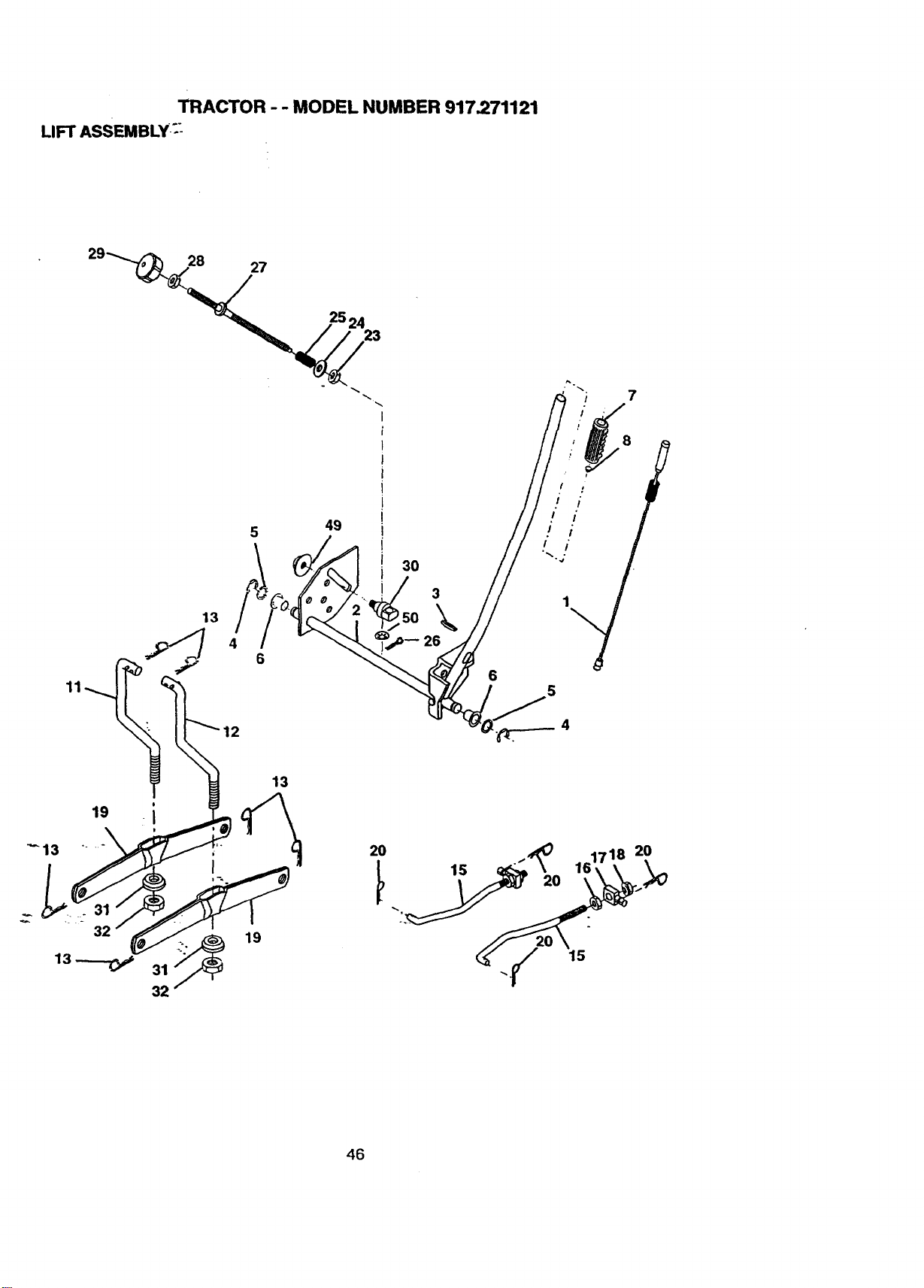
TRACTOR - - MODEL NUMBER 917.271121
LIFT ASSEMBLY_:
28
27
2524
23
5
13
30
3
\
6
20 20
46
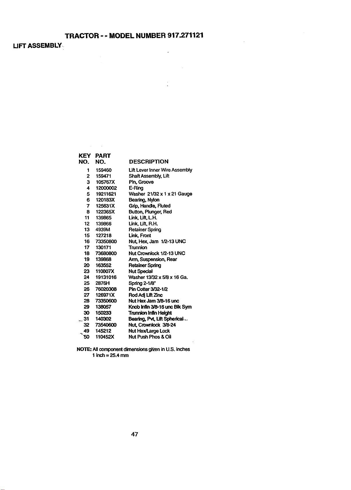
TRACTOR - - MODEL NUMBER 917.271121
LIFT ASSEMBLY
KEY PART
NO. NO. DESCRIPTION
1 159460 LiftLever InnerWire Assembly
2 159471 ShaftAssembly,Lift
3 105767X Pin,Groove
4 12000002 E-Ring
5 19211621 Washer 21/32 x I x 21 Gauge
6 120183X Bearing,Nylon
7 125631X Grip,Handle, Fluted
8 122365X Button,Plunger,Red
11 139865 Link,Uft, LH.
12 139866 Unk, Lift,R.H.
13 4939M RetainerSpring
15 127218 Unk, Front
16 73350800 Nut, Hex,Jam 1/2-13 UNC
17 130171 Trunnion
18 73680800 Nut Crownlock1/2-13UNC
19 139868 Arm, Suspension,Rear
20 163552 RetainerSpdng
23 110807X Nut Special
24 19131016 Washer 13/32x 5/8 x 16 Ga.
25 28761-1 Spring2-1/8"
26 76020308 PinCotter3/32-1/2
27 126971X RodAdjLift7inc
28 73350600 Nut FlexJam 3/8-16 unc
29 138057 KnobInfin3/8-16 uricBIkSym
30 150233 TrunnionInflnHeight
,.. 31 140302 Bearing,Pvt,LiftSpherical...
32 73540600 Nut,Crownlock3/8-24
49 145212 Nut Hex/LargeLock
50 110452X Nut PushPhos&On
NOTE: All componentdimensionsgiveninU.S. inches
1 inch= 25.4 mm
47
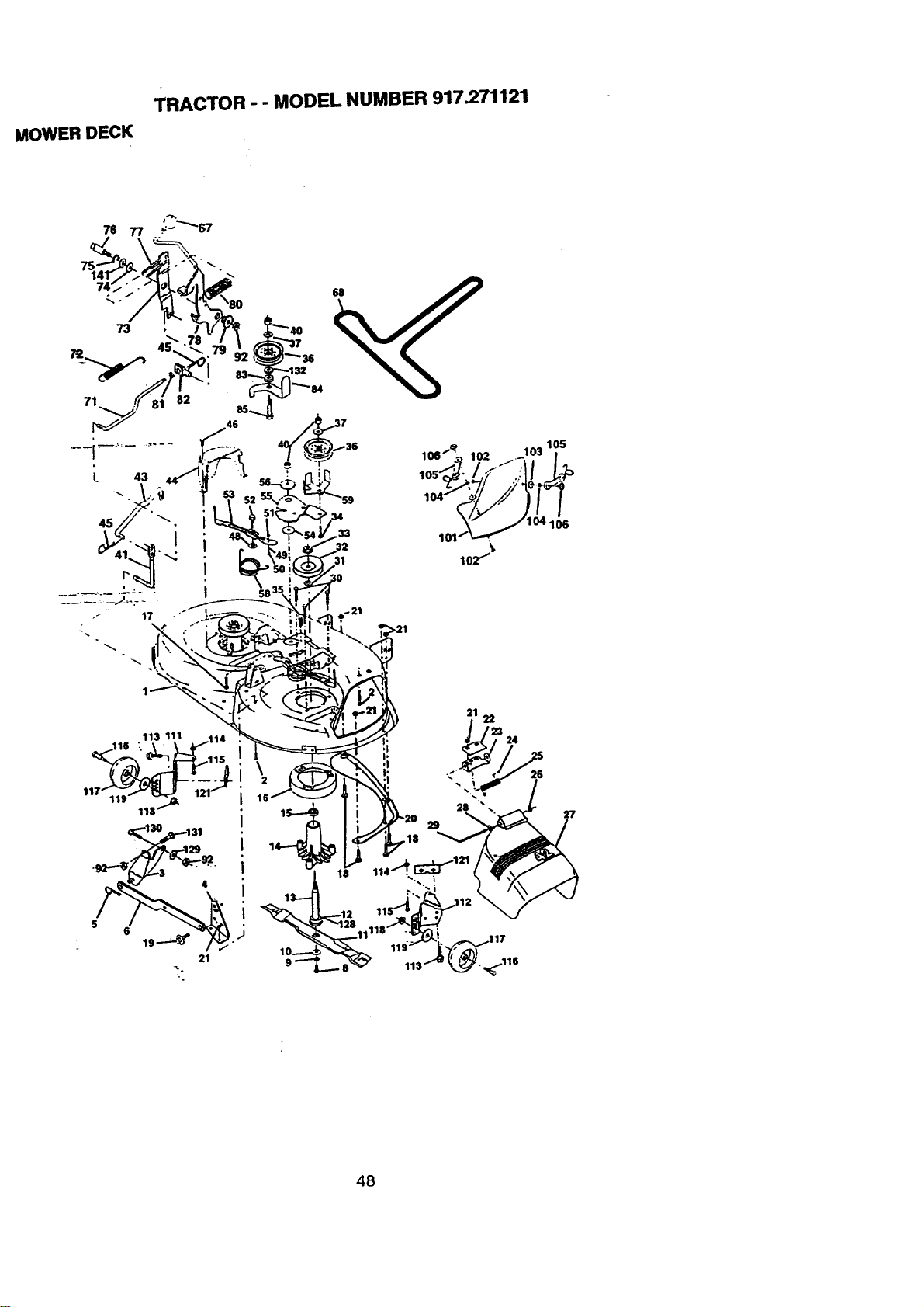
TRACTOR -- MODEL NUMBER 917.271121
MOWER DECK
S
6
lO5
106
48
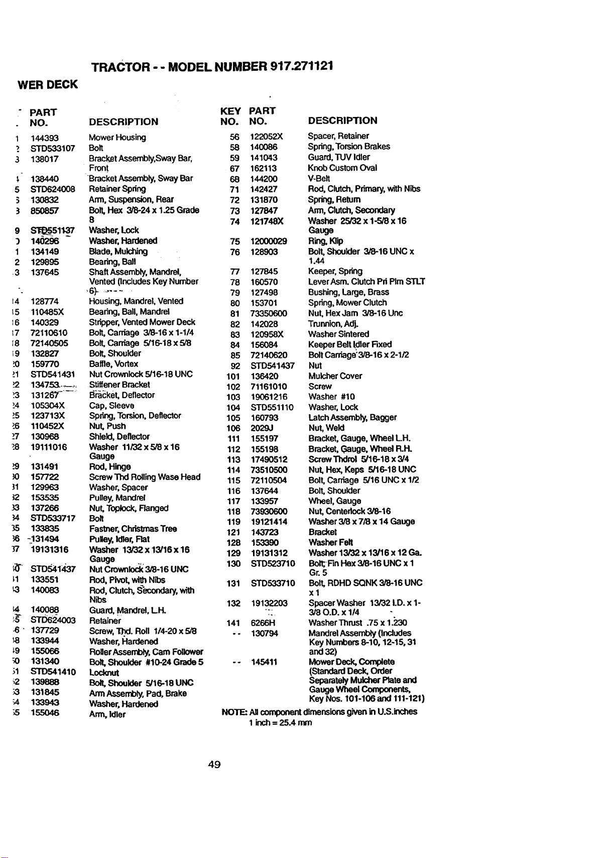
TRACTOR - - MODEL NUMBER 917.271121
WER DECK
PART
NO.
I 144393
? STD533107
3 138017
138440
5 STD624008
5 130832
3 85O857
9 _1137
_) 140296
1 134149
2 129895
•3 137645
t4 128774
15 110485X
6 140329
t7 72110610
_8 72140505
19 132827
;0 159770
.>1 STD541431
'.2 134753. ....
:3 13126"/....
'.4 105304X
.>5 123713X
_.6 110452X
Z7 130968
_.8 19111016
131491
30 157722
]1 129963
32 153535
33 137266
34 STD533717
35 133835
_6 -131494
37 19131316
_ STD,_.37
rl 133551
_3 140o83
_4 14OO88
I._ ST1_624003
-6 137729
133944
_9 155066
i0 131340
;1 STD541410
_2 139888
;3 131845
i4 133943
;5 155046
KEY PART
DESCRIPTION NO. NO.
Mower Housing 56 122052X
Bolt 58 14O086
Bracket Assembly,Sway Bar, 59 141043
Front 67 162113
Bracket Assembly,Sway Bar 68 144200
RetainerSpdng 71 142427
Arm, Suspension,Rear 72 131870
Bolt, Hex 3/8-24 x 1.25 Grade 73 127847
8 74 121748X
Washer,Lock
Washer,Hardened 75
Blade,Mulching 76
Boaring, Ball
ShaftAssembly,Mandrel, 77
Vented(IncludesKey Number 78
.6)- ....... 79
Housing,Mandrel,Vented 80
Bearing,Ball,Mandrel 81
Stripper,VentedMower Deck 82
Bolt, Carriage 3/6-16 x 1-1/4 83
Bolt, Carriage 5/16-18 x 5/8 84
Bolt, Shoulder 85
Baffle,Vortex 92
Nut Cmwnlock 5/16-18 UNC 101
StiffenerBracket 102
I_mckeLDeflector 103
Cap, Sleeve 104
Spdng,Torsion,Deflector 105
Nut,Push 106
Shield,Deflector 111
Washer 11/32 x5/8 x16 112
Gauge 113
Rod,Hinge 114
ScrewThd RollingWase Head 115
Washer,Spacer 116
Pulley,Mandrel 117
Nut,Toplock,Flanged 118
13oJt 119
Fastner,ChristmasTree 121
Pulley,Idler, Rat 128
Washer 13/32 x 13/16 x 16 129
Gauge
NutCrownlo_ 3/8-16 UNC 130
Rod,Pivot,with Nibs 131
ROd,Clutch, S_dary, with
N_s 132 19132203
Guard, Mandrel, LH. -::.
Retainer 141 6266H
Screw, Thd. Roll 114-20x 5/8 - - 130794
Washer,I'lardened
RollerAssembly,Cam Follower
Bolt,Shoulder #10-24 Grade 6 -- 145411
Lodmut
Bolt,Shoulder 5/16-18 UNC
AnnAssembly,Pad, Brake
Washer, Hardened
An'n,Idler
DESCRIPTION
Spacer, Retainer
Spring,TorsionBrakes
Guard,TUV Idler
KnobCustomOval
V-Belt
Rod,Clutch, Primary,withNilus
Spring,Return
Arm, Clutch,Secondmy
Washer 25/32 x 1-5/8 x16
Gauge
12000029 Ring,K]ip
128903 Bolt, Shoulder 3/8-16 UNC x
1.44
127845 Keeper, Spring
160570 LeverAsm. ClutchPriPImSTLT
127498 Bushing,Large,Brass
153701 Spring,Mower Clutch
73350600 Nut, HexJam 3/8-16 Unc
142028 Trunnion,Adj.
120958X Washer Sintered
156084 KeeperBelt I.dlerFixed
72140620 BoltCarriage'3/8-16 x 2-1/2
STD541437 Nut
136420 MulcherCover
71161010 Screw
19061216 Washer #10
STD551110 Washer,Lock
160793 LatchAssembly,Bagger
2029J Nut,Weld
155197 Bracket,Gauge, Wheel LH.
155198 Bracket,Gauge, Wheel FLH.
17490512 ScrewThdrol 5/16-18 x 3/4
73510500 Nut, He.x,Keps 5/16-18 UNC
72110504 Boll Carriage 5/16 UNC x 1/2
137644 Bolt, Shoulder
133957 Wheel, Gauge
73930600 Nut, Centeriock3/8-16
19121414 Washer3/8 x7/8 x 14 Gauge
143723 Bracket
153390 Washer Felt
19131312 Washer13/32 x 13/16 x 12 Ga.
STD523710 Bolt;Fin Flex3/8-16 UNC x1
Gr.5
STD533710 BolL RDHD SQNK 3/8-16 UNC
xl
SpacerWasher 13/32 I.D. x 1-
3/80.D. x 1/4
WasherThmst .75 x 1.230
MandrelAssembly(Includes
Key Numbers8-10, 12-15, 31
and32)
Mower Deck, Complete
(StandardDeck, Onder
SeparatelyMulcherPrateand
Gauge Wheel Components,
Key Nos. 101-106 and 111-121)
NOTE: All componentdimensionsgivenin U.S.inches
1 inch= 25.4 mm
49
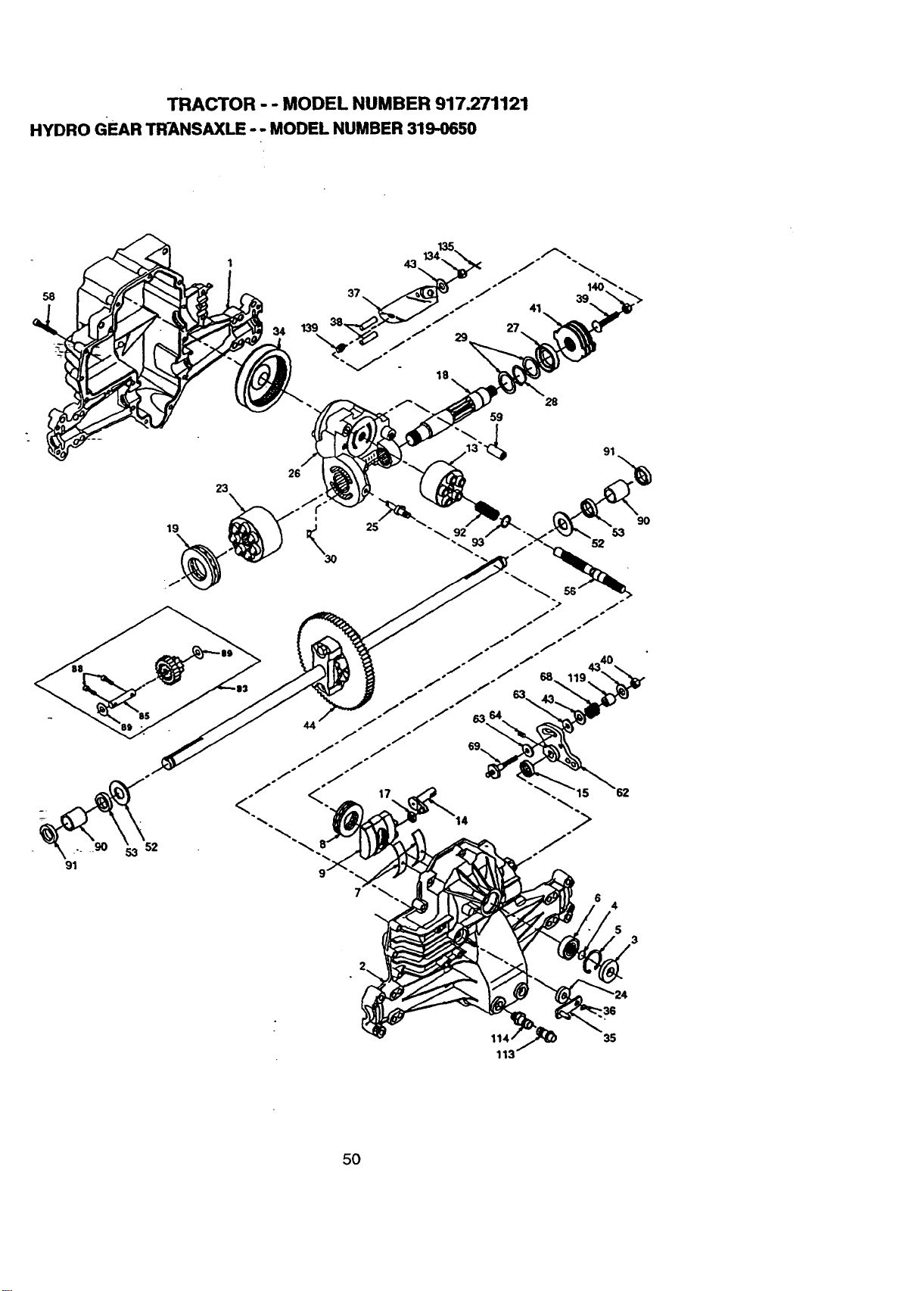
TRACTOR - - MODEL NUMBER 917.271121
HYDRO GEAR TR'ANSAXLE -- MODEL NUMBER 319-0650
58
• _52
91
19
23
26
59
91
- %
53
9O
7
4
5
3
36
35
113
5O

TRACTOR-- MODEL NUMBER 917.271121
HYDRO GEAR TRANSAXLE- - MODEL NUMBER 319-0650
KEY PART KEY PART
NO.NO. DESCRIPTION NO.NO. DESCRIPTION
1 142930 Housing,Lower 43 142884
2 142931 Assembly,UpperHousing 44 150829
--3_-142932 Seal, Up 52 142991
_--- 142928 Ring,Wire Retaining 53 142961
5 142933 Ring,Retaining . 56 142963
6 142934 Bearing,ShaftBall 58 142964
7 142935 Bearing, Cradle 58 142965
8 150771 Bearing,Thrust 30 x 52 x 13 62 142966
9 14-293-7......... Swashplate, Variable 63 142967
13 142938 Block,Cylinder Assembly 64 142920
14 142939 Arm, Trunnion 68 142969
15 142940 Seal, Up 69 144610
17 142941 Guide, Slot 83 142971
18 150772 Shaft, Motor 85 150806
19 150773 Bearing,Thrust 42x68x16 88 142973
23 142944 Block,CylinderAssembly 89 142974
24 142945 Seal, Lip 10 x25 x7 90 142975
25 --143946 ........ Actuator,Bypass 91 142976
26 -_1_-7_4 ....... Center SectionAssemblyKit 92 142977
27 142948 Seal, Up 26 x 42 x 8 93 142978
28 142949 Ring, Retaining 113 142917
29 142950 Washer 26 x35 x I 114 142918
30 150787 Plate, Bypass 119 142980
34 142951 Oil FilterElement 134 144607
35 _142952 Arm, Bypass 135144608
36 142953 Ring, Retaining 139150775
- 37 142954 Arm, Actuating 140150776
38 142955 Pin,Actuating
39 150777 Belt 5/16-24 x 1-3/4
40 150778 Locknut,Hex 5/16-24 UNJC
41 142958 Brake Rotor/StatorKTd
Washer 7116x 7/8 x .060
DifferentialAssembly
Washer 3/4 x 1.5 x .13
Seal .75 x 1.25x .250
Shaft,Input
Belt 1/4-20 x 1.38
Pin .50D x .43 ID x .750
Arm, Control
Puck, Dampener
Set Screw
Spring
Stud 5/16-24
Jack,shaftAssembly
Jackshaft -
Screw,Cap
Washer 7116x 1 x 1/2
Sleeve Bearing
Seal, Wiper
Spring, Block
Washer, BlockThrust
Cap, VentAssembly
F_ng, O-RingAssembly
Spacer
Nut,Castle 5/16-24
Pin,Cotter
spring,Compression
Nut,Hex 5/16-24
NOTE: AllcomponentdimensionsgiveninU.S. inches
1inch= 25.4 mm
51
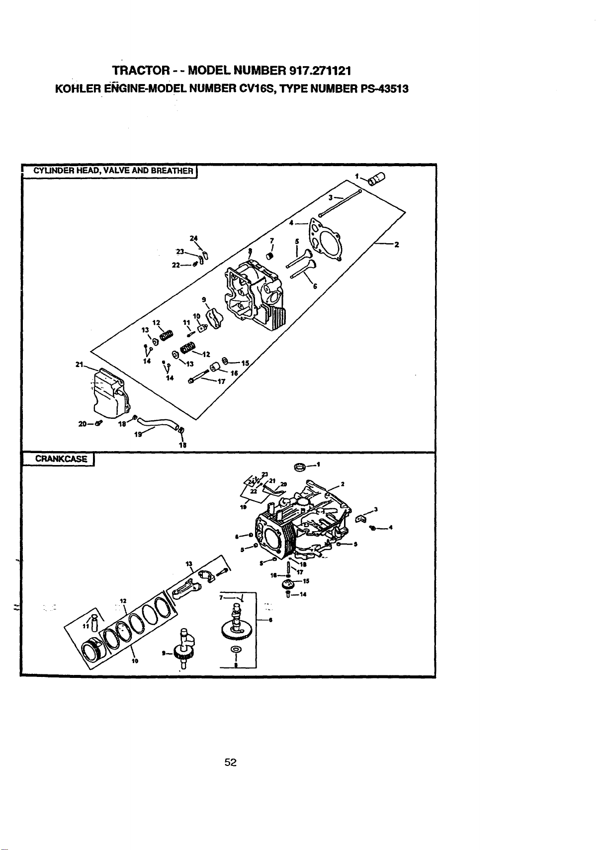
TRACTOR - - MODEL NUMBER 917.271121
KOHLER E_INE-MODEL NUMBER CV16S, TYPE NUMBER PS-43513
i
I CYLINDER HEAD, VALVE AND BREATHER J
24 7
i
c_c_s_ I
12
10
)----15
_14
6
52
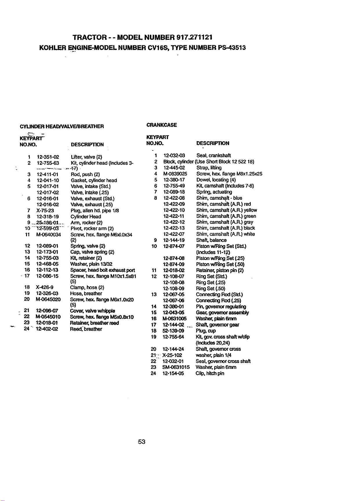
TRACTOR -- MODEL NUMBER 917.271121
KOHLER ENGINE-MODEL NUMBER CV16S, TYPE NUMBER PS-43513
CYMNDER HEAD/VALVE/BREATHER
NO.NO. DESCRIPTION
1 12-351-02 Ufter, valve (2)
2 12-755-63 Kit,cylinderhead(Includes3-
.......... ,-- -17) -
3 12411-01 Rod, push(2)
4 12041-10 Gasket,cylinderhead
5 12-017-01 Valve,intake(Std.)
12.O17-02 Valve, intake (.25)
6 12-016-01 Valve,exhaust(Std.)
12-O16-02 Valve, exhaust(.25)
7 X-75-23 Plug,allen hal.pipe1/8
8 12-318-19 CylinderHead
9 __25_.86-01_.. Arm, rocker(2)
10 --12-':5"_J'-03..... Pivot,rocker arm (2)
11 M-0640034 Screw,hex. flange M6_d.Ox34
(2)
12 12-089-01 Spring,valve (2)
13 12-173-01 Cap, valvespdng(2)
14 12-755-03 Irdt,retainer (2)
15 12-468-05 Washer, plain13/32
16 12-112-13 Spacer,head boltexhaustport
17 12-086-15 Screw, hex. flangeM10x1.5x81
(5)
18 X-426-9 Clamp,hose (2)
19 12-326-O3 Hose,breather
20 M-0645020 Screw, hex.flange M6x1.0x20
(5)
21 12-O96-O7 Cover,valve w/nipple
22 M-054,5010 Screw, hex.flangeM5x0.8xl0
23 12-018-01 Retainer, breatherreed
24 " 12-402-02 Reed;breather
CRANKCASE
KEYPART
NO.NO. DESCRIPTION
1 12-032-03 Seal, crankshaft
2 Block,cylinder(Use ShortBlock12 522 18)
3 12-445-02 Strap,lilting
4 M-0839025 Screw,hex.flange M8xl.25x25
5 12-380-17 Dowel,locating(4)
6 12-755-49 Kit,camshaft(Includes 7-8)
7 12-089-18 Spring,actuating
8 12-422-08 Shim,camsha.ft- blue
12-422-09 Shim,camshaft (A.R.) red
12-422-10 Shim,camshaft (A.R.) yellow
12-422-11 Shim,camshalt(A.R.) green
12-422-12 Shim, camshaft(A.R.) gray
12-422-13 Shim,camshaft (A.R.) black
12-422-O7 Shim, camshaft(A.R.) white
9 12-144-19 Shaft,balance
10 12-874-07 Pistonw/RingSet (Std.)
(Includes11-1,2)
12-874-08 Pistonw_'_.Set (.25)
12,874-09 Pistonw/RingSet (.50)
11 12-018-02 Retainer,pistonpin(2)
12 12-108-07 RingSet (Std.)
12-108-08 RingSet (.25)
12-108-09 RingSet (.50)
13 12-O67-05 ConnectingRod (Std.)
12-067-06 ConnectingRod4.25)
14 12-380-01 Pin,governorregulating
15 12-043-05 Gear, governorassembly
16 M-0631005 Washar,plaln6rnm
17 12-144-02 .... Shaft,governorgear
18 52-139-09 Plug, cup
19 12-755-64 I_t,gov.crossshaftw/clip
(Includes 20,24)
20 12-144-24 Shaft, governorcross
21:: X-25-102 washer,plain114
22 12-032-01 Seal, governorcrossshaft
23 SM-0631015 Washer,plain6n'_n
24 12-154-05 Clip, hitchpin
53
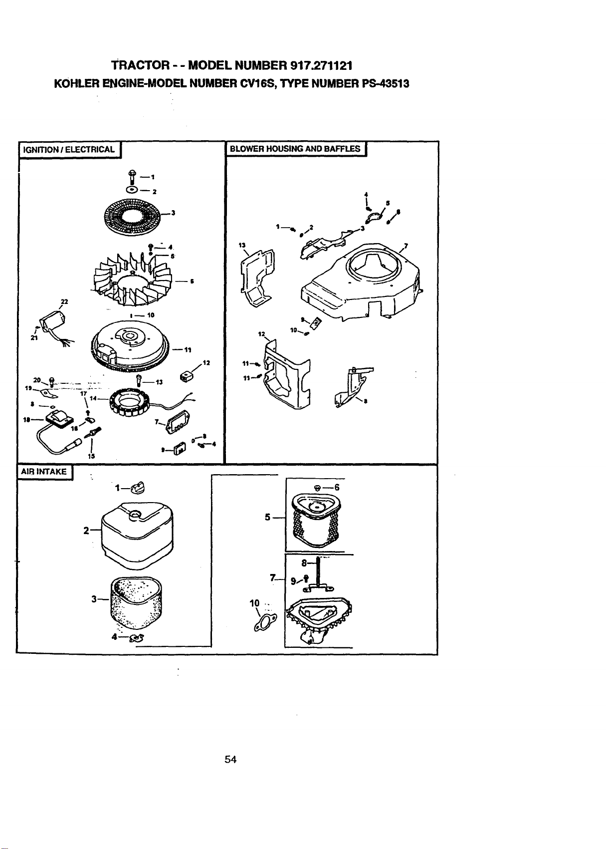
TRACTOR - - MODEL NUMBER 917.271121
KOHLER ENGINE-MODEL NUMBER CV16S, TYPE NUMBER PS-43513
IGNITION I ELECTRICAL !
22
/
(_--2
t -.-L-4.
--11
._._/12
i i
AIR INTAKE I ,
1_ 8
4--_,
BLOWER,, HOUSING AND BAFFLES I
4
I s
54
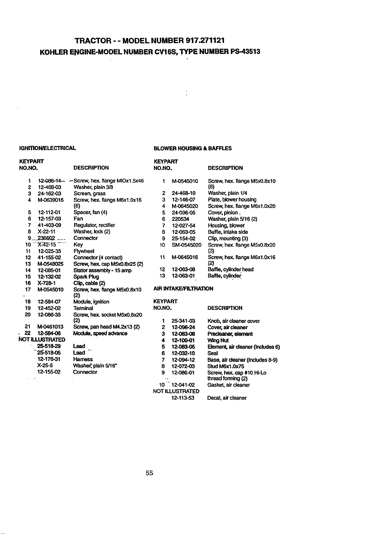
TRACTOR - - MODEL NUMBER 917.271121
KOHLER EI_IGINE-MODEL NUMBER CV16S, TYPE NUMBER PS-43513
IG_N/ELECTRICAL BLOWER HOUSING & BAFFLES
KEYPART KEYPART
NO.NO. DESCRIPTION NO.NO. DESCRIPTION
1 1-2-086-1-4--....Screw,hex.flange MlOxl.Sx46
2 12-468-03 Washer, plain3/8
3 24-162-03 Screen,grass
4 M-0639016 Screw,hex.flange M6x1.0x16
(6)
5 12-112-01 Spacer,fan (4)
6 12-157-03 Fan
7 41-403-09 Regulator,rectifier
8 X-22-11 Washer, lock(2)
9__2366Q2 ..... Connector
10--X:_P2-T5 ...... Key
11 12-025-35 Flywheel
12 41-155-02 Connector (4 contact)
13 M-0548025 Screw, he.x.capM5xO.Sx25(2)
14 12-O85-01 Stator assembly- 15amp
15 12-132-02 Spark Plug
16 X-728-1 Clip, cable(2)
17 M-0545010 Screw, hex.flangeM5x0.8xl0
(2)
18 12-684-07 Module, ignition
19 12452-O2 Terminal
20 12-086-35 Screw,hex. socketM5xO.8x20
(2)
21 M-0461013 Screw, pan headM4.2x13 (2)
22 12-58406 Module, speedadvance
NOT ILLUSTRATED
25-518-29 Lead
"25"-518-05 Lead ....
12-176-31 Harness
X-25-5 WasheP,plain5/16"
12-155-02 Connector
1 M-0545010 Screw, hex.flange M5xO.8xlO
(8)
2 24-468-10 Washer,plain1/4
3 12-146-07 Plate, blowerhousing
4 M-0645020 Screw, hex.flange M6xl.0x20
5 24-096-05 Cover,pinion.
6 220534 Washer,plain5/16 (2)
7 12-O27-54 Housing,blower
8 12-O63-05 Baffle,intakeside
9 25-154-02 Clip, mounting(3)
10 SM-0545020 Screw, hex.flange M5x0.Sx20
(3)
11 M-0645016 Screw, hex.flange M6xl.0x16
(2)
12 12063-08 Baffle, cylinder,head
13 12-063-01 Baffle, cyU.nder
AIR INTAKE/FILTRATION
KEYPART
NO.NO.
DESCRIPTION
1 25-341-O3
2 12-096-24
3 12-083-08
4 12-100-01
5 12.O83-05
6 12-032-10
7 12-094-12
8 12-072-03
9 12-086--01
.°
10 12-041-02
NOT ILLUSTRATED
12-113-53
Knob,aircleanercover
Cover, ak"cleaner
Precleaner,element
WingNut
Element,ak cleaner(Includes6)
Seal
Base, aircleaner(Includes8-9)
StudM6x1.0x75
Screw,hex.cap #10Hi-Lo
threadforming(2)
Gasket,aircleaner
Decal,aircleaner
55
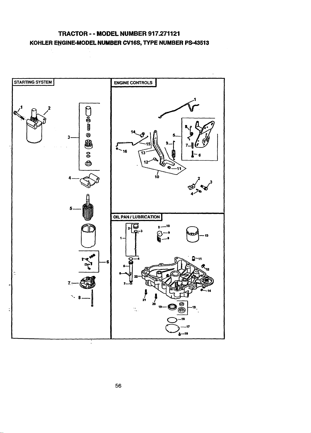
TRACTOR - - MODEL NUMBER 917.271121
KOHLER ENGINE-MODEL NUMBER CV16S, TYPE NUMBER PS-43513
STARTING SYSTEM J
<3
O
o
ENGINE CONTROLS J
lO
2
OIL PAN ' LUBR!CATION I
0---4
56
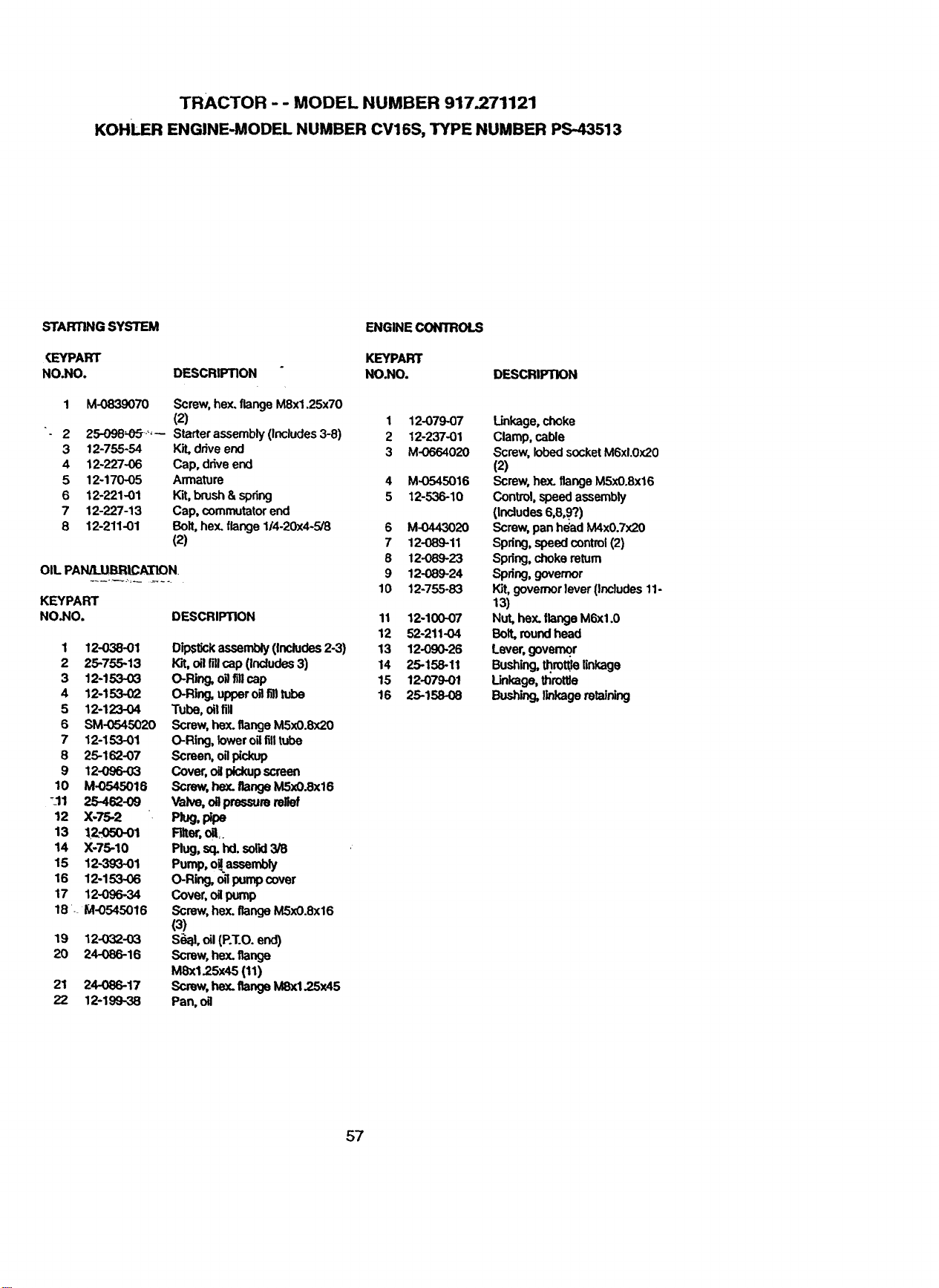
TRACTOR - - MODEL NUMBER 917.271121
KOHLER ENGINE-MODEL NUMBER CV16S, TYPE NUMBER PS-43513
STARTING SYSTEM
ENGINE CONTROLS
KEYPART
DESCRIPTION NO.NO. DESCRIPTION
1 M-0839070
2 25-098_5" .....
3 12-755-54
4 12-227,<)6
5 12-170-05
6 12-221-01
7 12-227-13
8 12-211-01
Screw,hex.flangeM8x1.25x70
(2)
Starterassembly(Includes3-8)
Kit,driveend
Cap, driveend
Armature
Kit,brush & spdng
Cap, commutatorend
Bolt,hex.flange1/4-20x4-5/8
(2)
OIL PAN_JJBRICh3[1ON
KEYPART
NO.NO.
DESCRIPTION
1 12-038-01
2 25-755-13
3 12-15303
4 12-153-02
5 12-123-04
6 SM`0545020
7 12-153-01
8 25-162-07
9 12-096.-03
10 M-0545016
-11 25-462-09
12 X-75-2
13 12,-050-01
14 X-75-10
15 12-393`01
16 12o153`06
17 12096-34
18 M-0545016
19 12-032-03
20 24-086-16
21 24-086-17
22 12-199-38
Dip_Uckassembly(Includes2-3)
Kit, oil fillcap (Includes3)
O-Ring, oilfillcap
O-Ring, upperonfilltube
Tube, oil fill
Screw,hex. flange MSxO.8x20
O-Ring, loweroilfilltube
Screen, oilpickup
Cover,oilpickupscreen
Screw, hex. flangeM5xO.Sx16
Valve,oilpressurerelief
P_, ppe
Filter,oil,.
Plug, so,.hd.solid3/8
Pump,oaassembly
O-Ring, oilpumpcover
Cover, oilpump
Screw,hex. flangeMSxO.Sx16
(3)
S_I, oil (P.T.O.end)
Screw, hex. flange
M8xl.25x45 (11)
Screw,hex.flangeM8x1.25x45
Pan, oil
1 12-079-07 Linkage,choke
2 12-237-01 Clamp,cable
3 M`0664020 Screw,lobed socketM6xl.0x20
(2)
4 M_To45016 Screw, hex. flange MSxO.8x16
5 12-536-10 Control, speedassembly
(Includes6,8,9?)
6 M`0443020 Screw,pan head M4x0.Tx20
7 12-089-11 Spflng,speedcontrol (2)
8 12-089-23 Spring,chokereturn
9 12-089-24 Spring,governor
10 12-755-83 Kit,governorlever(Includes11-
13)
11 12-100-07 Nut, hex.flange M6xl.0
12 52o211`04 Bolt, roundhead
13 12-090-26 Lever,goverr_r
14 25-158-11 Bushing,ti).ro_elinkage
15 12`079-01 Linkage,throttle
16 25-15808 Bushing,linkagemtaining
57

58

SUGGESTED GUIDE FOR SIGHTING SLOPES FOR SAFE OPERATION
b' /
U1
_D
SIGHTING _" _ ..CUT
GUIDE TH_
ONLY, RIDE UP AND DOWN HILL,
NOT ACROSS HILL
SIGHT AND HOLD THIS LEVEL WITH
SKY LINE OR TREE.
15° MAX.
| ii
Operate your Tractor up and down the face of slopes (not I
greater than 15°), never across the face. Make turns gradu-
I
ally to prevent tipping or loss of control. Exercise extreme
caution when changing direction on slopes.
I r_l n

For the repair or re.placement pads you need
delivered directly t6-your home.
Call-_am -7 pm, 7 days a week
1-800-366-PART
(1-800-366-7278)
Para ordenar piezas con entrega a
domicilio - 1-800-659-7084
For in-house major brand repair service
Call 24 hours a day, 7 days a week
1-800-4-REPAIR
(1-800-473-7274)
Para pedir servicio de reparaci6n a
domicilio - 1-800-676-5811
For the location of a Sears Parts and
Repair Center in your area
Call 24 hours a day, 7 days a week
1-800-488-1222
For information on purchasing a Sears
Maintenance Agreement or to inquire
about an existing Agreement
Call 9 am - 5 pm, Monday-Saturday
1-800-827-6655
When requesting service-or ordering
parts, always provide the following
:=information:
• Product Type • Part Number
° Model Number ° Piart Description
S£ARS
America's Repair Speciailsts
165066 03.19.98 VB Printed in U.S.A.