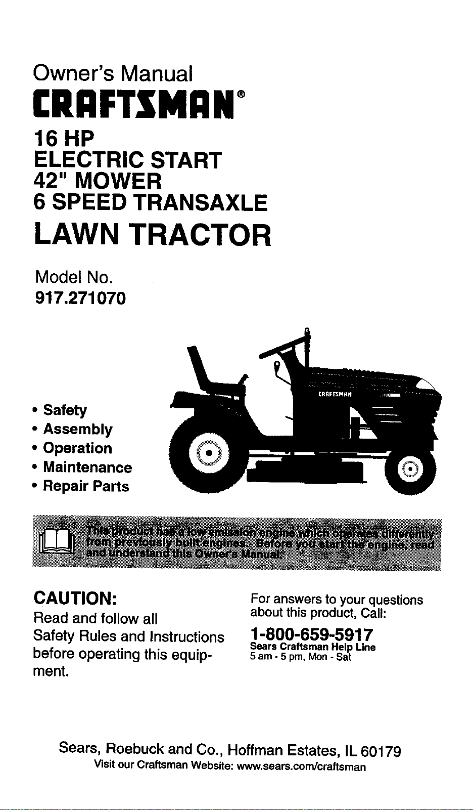
Owner's Manual
£RAFTSl4ANo
16 HP
ELECTRIC START
42" MOWER
6 SPEED TRANSAXLE
LAWN TRACTOR
Model No.
917.271070
• Safety
• Assembly
• Operation
• Maintenance
• Repair Parts
CAUTION:
Read and follow all
Safety Rules and Instructions
before operating this equip-
ment.
For answers to your questions
about this product, Call:
1-800-659-5917
Sears Craftsman Help Line
5 am - 5 pro, Mon- Sat
Sears, Roebuck and Co., Hoffman Estates, IL 60179
Visit our Craftsman Website: www.sears.condcraftsman
Warranty ............... _................................. 2
Safety Rules ........................................... 2
Product Specifications ........................... 5
Assembly ................................................ 8
Operation .............................................. 12
Maintenance Schedule ......................... 18
Maintenance ......................................... 18
Service and Adjustments ...................... 22
Storage ................................................. 27
Troubleshooting .................................... 28
Repair Parts ......................................... 32
Parts Ordering ....................... Back Cover
LIMITED'TWO YEAR WARRANTY ON CRAFTSMAN RIDING EQUIPMENT
For two (2) years fi'om the date of purchase, if this Craftsman Riding Equipment is main-
tained, lubricated and tuned up according to the instructions in the owner's manual,
Sears will repair or replace, free of charge, any parts found to be defective in material or
workmanship.
This Warranty does not cover:
• Expendable items which become worn during normal use, such as blades, spark
plugs, air cleaners, belts, etc.
• Tire replacement or repair caused by punctures from outside objects, such as nails,
thorns, stumps, or glass.
• Repairs necessary because of operator abuse, negligence, improper storage or acci-
dent or the failure to maintain the equipment according to the instructions contained in
the owner's manual.
• Riding equipment used for commercial or rental purposes.
LIMITED 90 DAY WARRANTY ON BAT-rERY
For ninety (90) days from date of purchase, if any battery included with this riding equip-
ment proves defective in material or workmanship and our testing determines the bat-
tery will not hold a charge, Sears will replace the battery at no charge. In-home warranty
service on your Craftsman riding equipment is available at no charge for 30 days from
the date of purchase. Please contact your nearest service center. After 30 days from the
date of purchase, warranty service is available by taking your Craftsman riding equip-
ment to your nearest Sears Service Center. (In-home warranty service will still be avail-
able at(er 30 days from the date of purchase but a standard trip charge will apply). This
warranty applies only while this product is in the United States. This Warranty gives you
specific legal rights, and you may also have other rights which may vary from state to
state.
Sears, Roebuck and Co., D/817 WA, Hoffman Estates, IL 60179
GENERAL OPERATION
• Read, understand, and fellow all instruc-
tions in the manual and on the machine
before starting.
• Only allow responsible adults, who are
familiar with the instructions, to operate
the machine.
Clear the area of objects such as rocks,
toys, wire, etc., which could be picked
up and thrown by the blade.
• Be sure the area is clear of other people
before mowing. Stop machine if anyone
enters the area.
• Never carry passengers.
• Do not mow in reverse unless absolute-
ly necessary. Always look down and
behind before and while backing.
• Be aware of the mower discharge direc-
tion and do not point it at anyone. Do
not operate the mower without either
the entire grass catcher or the guard in
place.
• Slow down before turning.
• Never leave a running machine unat-
tended. Always turn off blades, set park-
ing brake, stop engine, and remove
keys before dismounting.
• Turn off blades when not mowing.
• Stop engine before removing grass
catcher or unclogging chute.
• Mow only in daylight or good artificial
light.
• Do not operate the machine while under
the influence of alcohol or drugs.
• Watch for traffic when operating near or
crossing roadways.
• Use extra care when loading or unload-
ing the machine into a trailer or truck.
SLOPE OPERATION
Slopes are a major factor related to loss-
of-control and tipover accidents, which
can result in severe injury or death. All
slopes require extra caution. If you cannot
back up the slope or if you feel uneasy on
it, do not mow it.
DO:
• Mow up and down slopes, not across.
• Remove obstacles such as rocks, tree
limbs, etc.
• Watch for holes, ruts, or bumps. Uneven
terrain could overturn the machine. Tall
grass can hide obstacles.
• Use slow speed. Choose a low gear so
that you will not have to stop or shift
while on the slope.
• Follow the manufacturer's recommen-
dations for wheel weights or counter-
weights to improve stability.
• Use extra care with grass catchers or
other attachments. These can change
the stability of the machine.
• Keep all movement on the slopes slow
and gradual. Do not make sudden
changes in speed or direction.
• Avoid starting or stopping on a slope. If
tires lose traction, disengage the blades
and proceed slowly straight down the
slope.
DO NOT:
• Do notturn on slopes unless necessary,
and then, turn slowly and gradually
downhill, if possible.
• Do not mow near drop-offs, ditches, or
embankments. The mower could sud-
denly turn over if a wheel is over the
edge of a cliff or ditch, or if an edge
caves in.
• Do not mow on wet grass. Reduced
traction could cause sliding.
• DO nottry to stabilize the machine by
putting your foot on the ground.
• Do not use grass catcher on steep
slopes.
CHILDREN
Tragic accidents can occur if the operator
is not alert to the presence of children.
Children are often attracted to the
machine and the mowing activity. Never
assume that children will remain where
you last saw them.
• Keep children out of the mowing area
and under the watchful care of another
responsible adult.
• Be alert and turn machine off if children
enter the area.
• Before and when backing, look behind
and down for small children.
• Never carry children. They may fall off
and be seriously injured or interfere with
safe machine operation.
• Never allow children to operate the
machine.
• Use extra care when approaching blind
corners, shrubs, trees, or other objects
that may obscure vision.
SERVICE
• Use extra care in handling gasoline and
other fuels. They are flammable and
vapors are explosive.
Use only an approved container.
Never remove gas cap or add fuel
with the engine running.Allow en-
gine to cool before refueling. Do not
smoke.
Never refuel the machine indoors.
Never store the machine or fuel
container inside where there is an
open flame, such as a water heater.
• Never run a machine inside a closed
area.
• Keep nuts and bolts, especially blade
attachment bolts, tight and keep equip-
ment in good condition.
• Never tamper with safety devices.
Check their proper operation regularly.
• Keep machine free of grass, leaves, or
other debris build-up. Clean oil or fuel
spillage. Allow machine to cool before
storing.
• Stop and inspect the equipment if you
strike an object. Repair, if necessary,
beforerestarting.
• Never make adjustments or repairs with
the engine running.
• Grass catcher components are subject
to wear, damage, and deterioration,
which could expose moving parts or
allow objects to be thrown. Frequently
check components and replace with
manufacturer's recommended parts,
when necessary.
• Mower blades are sharp and can cut.
Wrap the blade(s) or wear gloves, and
use extra caution when servicing them.
• Check brake operation frequently.
Adjust and service as required.
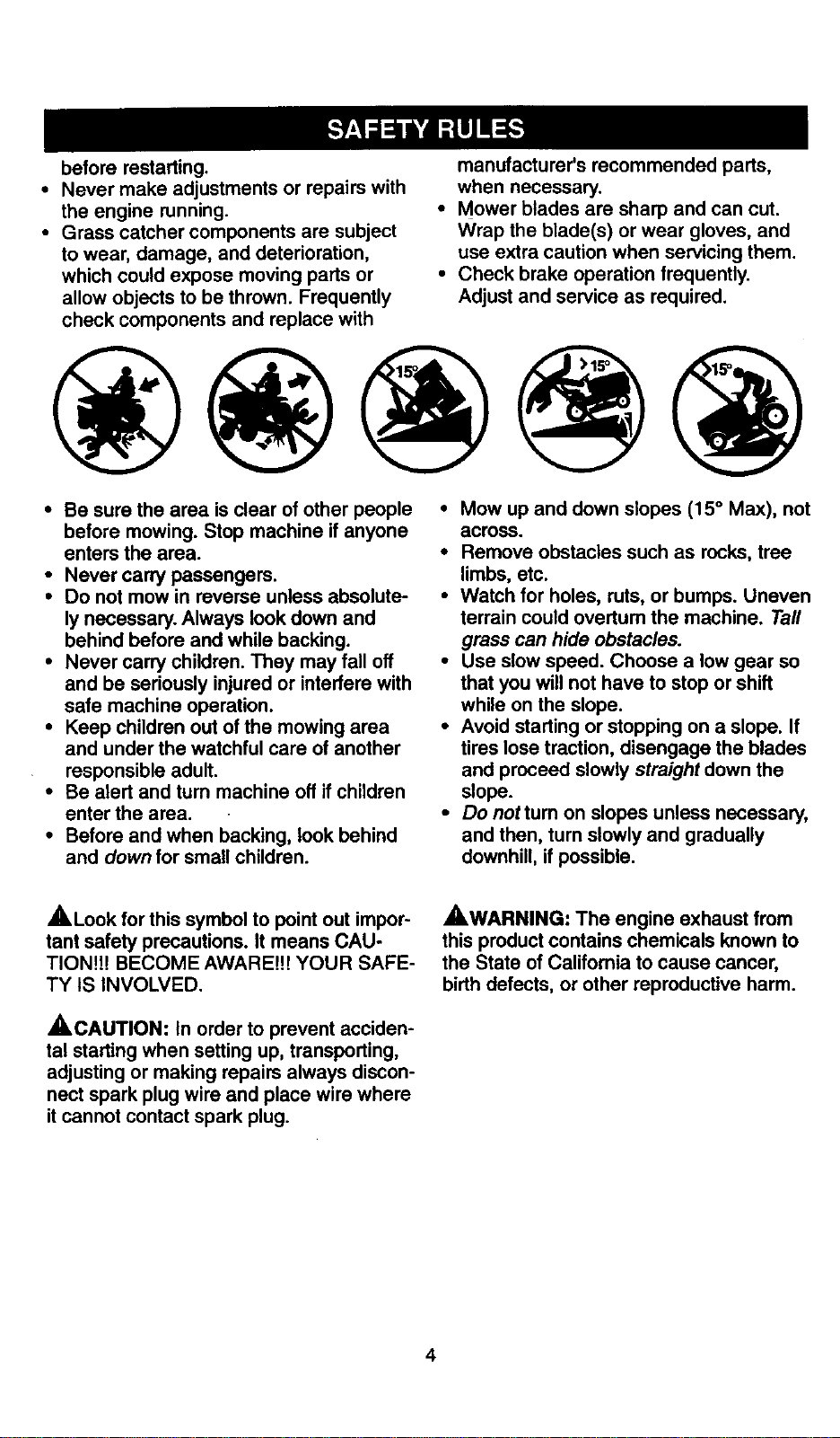
• Be sure the area is clear of other people
before mowing. Stop machine if anyone
enters the area.
• Never carry passengers.
• Do not mow in reverse unless absolute-
ly necessary. Always look down and
behind before and while backing.
• Never carry children. They may fall off
and be seriously injured or interfere with
safe machine operation.
• Keep children out of the mowing area
and under the watchful care of another
responsible adult.
• Be alert and turn machine off if children
enter the area.
• Before and when backing, look behind
and down for small children.
• Mow up and down slopes (15 ° Max), not
across.
• Remove obstacles such as rocks, tree
limbs, etc.
• Watch for holes, ruts, or bumps. Uneven
terrain could overturn the machine. Tall
grass can hide obstacles.
• Use slow speed. Choose a low gear so
that you will not have to stop or shift
while on the slope.
• Avoid starting or stopping on a slope. If
tires lose traction, disengage the blades
and proceed slowly straight down the
slope.
• Donottumonslopesunlessnecessary,
and then, turn slowly and gradually
downhill, if possible.
,_Look for this symbol to point out impor-
tant safety precautions. It means CAU-
TION!I! BECOME AWARE!!! YOUR SAFE-
TY IS INVOLVED.
_CAUTION: tn order to prevent acciden-
tal starting when setting up, transporting,
adjusting or making repairs always discon-
nect spark plug wire and place wire where
it cannot contact spark plug.
_WARNING: The engine exhaust from
this productcontains chemicals known to
the State of California to cause cancer,
birth defects, or other reproductive harm.
4
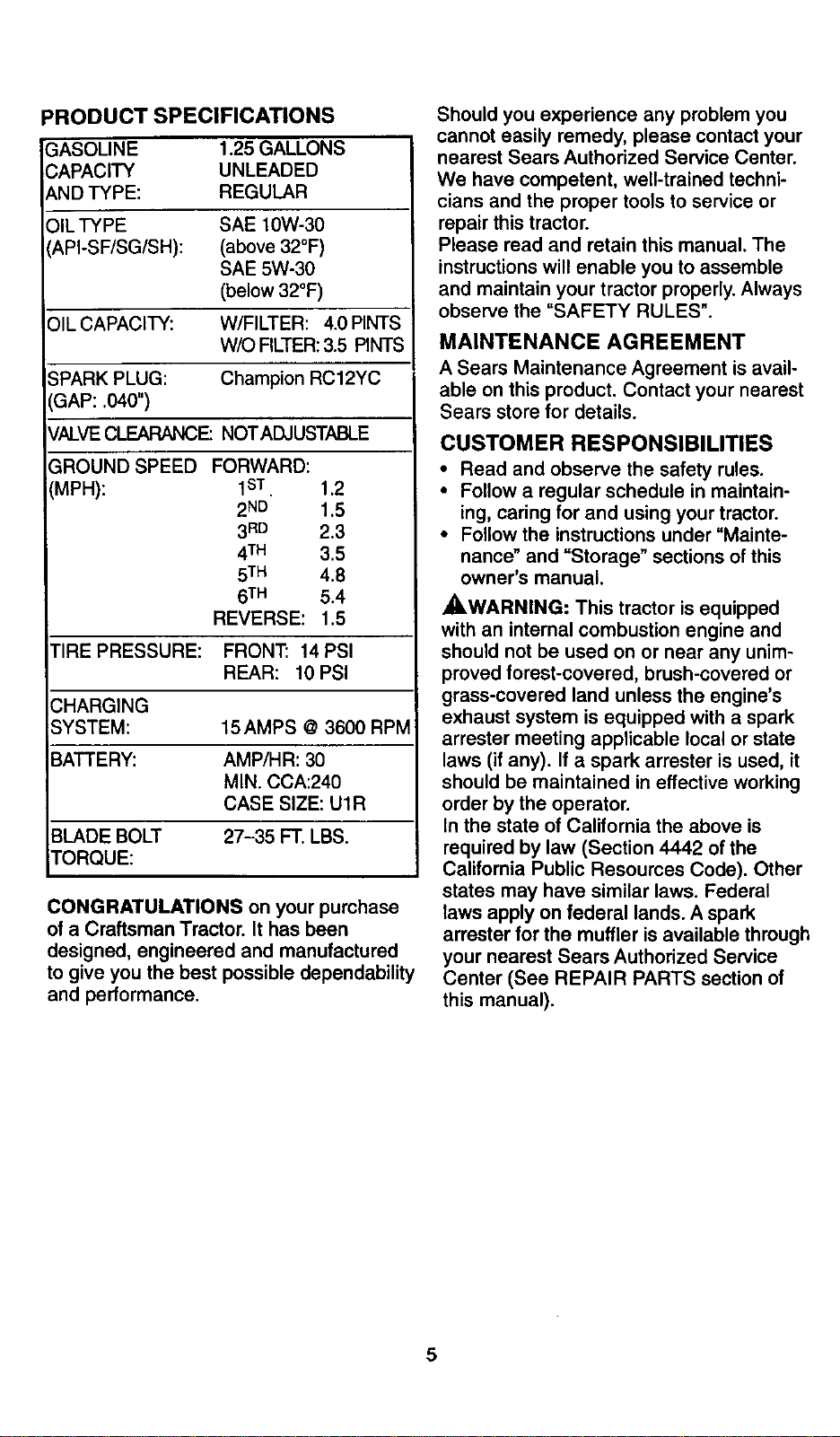
PRODUCT SPECIFICATIONS
GASOLINE 1.25GALLONS
CAPACITY UNLEADED
AND TYPE: REGULAR
_)ILTYPE SAE 10W-30
API-SF/SG/SH): (above 32°F)
SAE 5W-30
(below 32°F)
)IL CAPACITY: W/FILTER: 4.0 PINTS
W/O FILTER: 3.5 PINTS
;PARK PLUG: Champion RC12YC
3AP: .040")
VALVE CLEARANCE: NOTADJUSTABLE
GROUND SPEED
IMPH):
FORWARD:
1ST. 1.2
2ND 1.5
3RD 2.3
4TM 3.5
5TM 4.8
6TM 5.4
REVERSE: 1.5
TIRE PRESSURE: FRONT: 14 PSI
REAR: 10 PSI
CHARGING
SYSTEM: 15 AMPS @ 3600 RPM
BATTERY: AMP/HR: 30
MIN. CCA:240
CASE SIZE: U1R
BLADE BOLT 27-35 FT. LBS.
TORQUE:
CONGRATULATIONS on your purchase
of a Craftsman Tractor. It has been
designed, engineered and manufactured
to give you the best possible dependability
and performance.
Should you experience any problem you
cannot easily remedy, please contact your
nearest Sears Authorized Service Center.
We have competent, well-trained techni-
cians and the proper tools to service or
repair this tractor.
Please read and retain this manual. The
instructions will enable you to assemble
and maintain your tractor properly. Always
observe the "SAFETY RULES".
MAINTENANCE AGREEMENT
A Sears Maintenance Agreement is avail-
able on this product. Contact your nearest
Sears store for details.
CUSTOMER RESPONSIBILITIES
• Read and observe the safety rules.
• Follow a regular schedule in maintain-
ing, caring for and using your tractor.
• Follow the instructions under "Mainte-
nance" and "Storage" sections of this
owner's manual.
_WARNING: This tractor is equipped
with an internal combustion engine and
should not be used on or near any unim-
proved forest-covered, brush-covered or
grass-covered land unless the engine's
exhaust system is equipped with a spark
arrester meeting applicable local or state
laws (if any). If a spark arrester is used, it
should be maintained in effective working
order by the operator.
In the state of California the above is
required by law (Section 4442 of the
California Public Resources Code). Other
states may have similar laws. Federal
laws apply on federal lands. A spark
arrester for the muffler is available through
your nearest Sears Authorized Service
Center (See REPAIR PARTS section of
this manual).
5
0
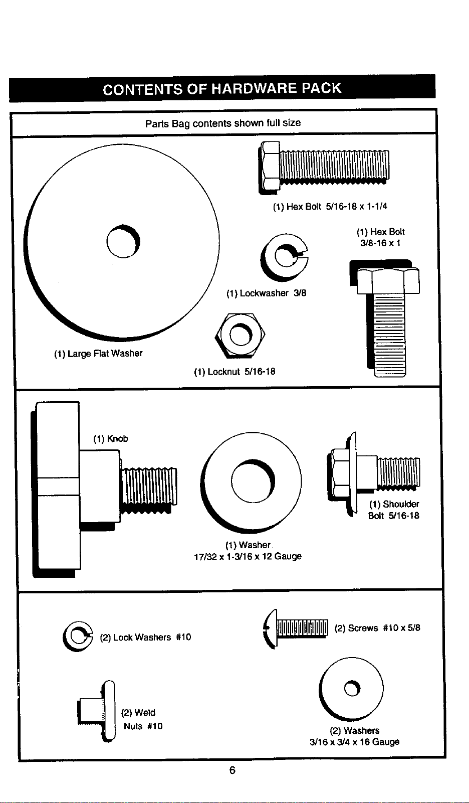
(1) Large Rat Washer
Parts Bag contents shown full size
(1) Hex Bolt 5/16-18 x 1-1/4
(1) Hex Bolt
3/8-16 x 1
(1) Lockwasher 3/8
@
(1) Locknut 5/16-18
(1) Knob
(1) Washer
17/32 x 1-3/16 x 12 Gauge
(1) Shoulder
Bolt 5/16-18
(2) Lock Washers #10
(2) Weld
Nuts #10
(2) Screws #10 x 5/8
(2) Washers
3/16 x 3/4 x 16 Gauge
6
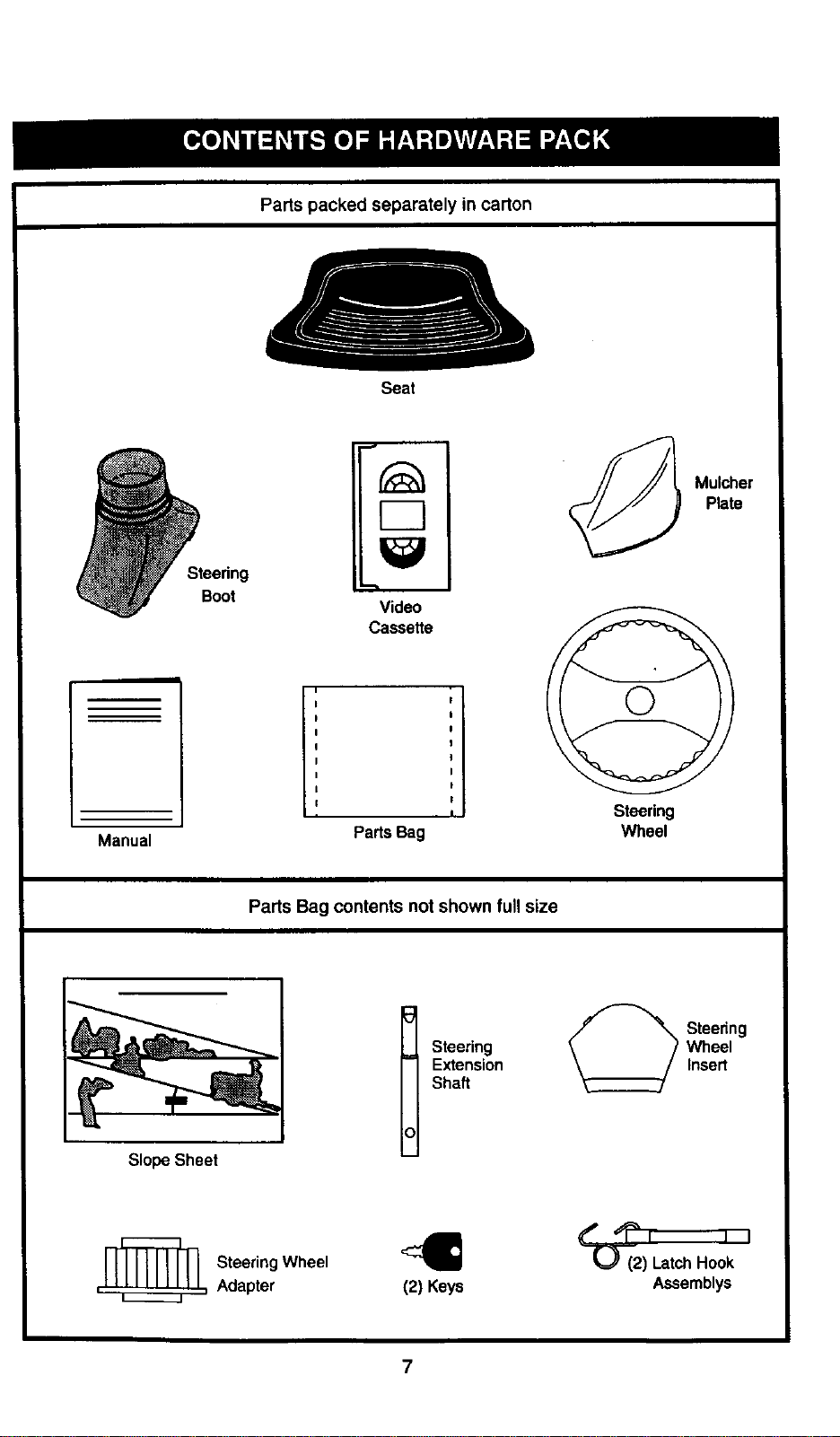
Parts packed separately in carton
Steering
Boot
Seat
Video
Cassette
Mulcher
Plate
Manual
PartsBag
Steering
Wheel
Parts Bag contents not shown full size
Slope Sheet
t teering
Extension
Shaft
_ teering
Wheel
Insert
[_ Steering Wheel
, , Adapter
(2) Keys
LatchHook
Assemblys
Your new tractor has been assembled at the factory with exception of those parts left
unassembled for shipping purposes. To ensure safe and proper operation of your tractor
all parts and hardware you assemble must be tightened securely. Use the correct tools
as necessary to insure proper tightness. Review the video cassette before you begin.
TOOLS REQUIRED FOR
ASSEMBLY
Asocket wrench set will make assembly
easier. Standard wrench sizes you need
are listed below.
(1) 9/16" wrench
(1) Utility knife
(2) 1/2" wrench
(1) Tire pressure
gauge
(1) 3/4" Socket w/
drive rachet
(1) Phillips Screw-
driver
When rightor left hand is mentioned in
this manual, it means, from your point of
view, when you are in the operating posi-
tion(seated behind the steering wheel).
TO REMOVE TRACTOR FROM
CARTON
UNPACK CARTON
• Remove all accessible loose parts and
parts boxes from shipping carton (See
page 6).
• Cut, from top to bottom, along lines on
all four comers of shipping carton, and
lay panels flat.
• Check for any additional loose parts or
boxes and remove.
BEFORE ROLLING TRACTOR OFF
SKID
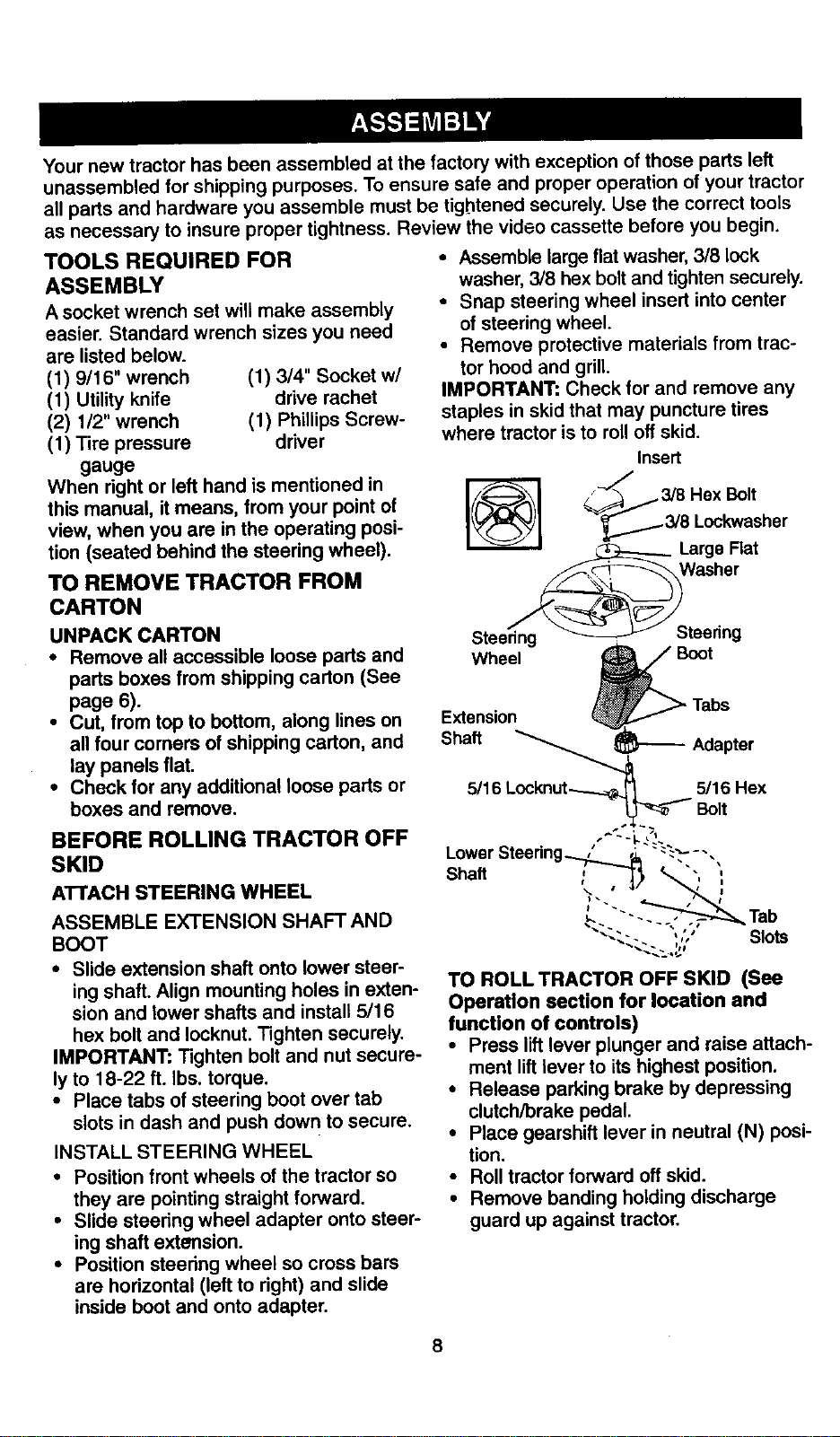
ATTACH STEERING WHEEL
ASSEMBLE EXTENSION SHAFT AND
BOOT
• Slide extension shaft onto lower steer-
ing shaft. Align mounting holes in exten-
sion and lower shafts and install 5/16
hex bolt and Iocknut. Tighten securely.
IMPORTANT: Tighten bolt and nut secure-
ly to 18-22 ft. Ibs. torque.
• Place tabs of steering boot over tab
slots in dash and push down to secure.
INSTALL STEERING WHEEL
• Position front wheels of the tractor so
they are pointing straight forward.
• Slide steering wheel adapter onto steer-
ing shaft extension.
• Position steering wheel so cross bars
are horizontal (left to right) and slide
inside boot and onto adapter.
• Assemble large flat washer, 3/8 lock
washer, 3/8 hex bolt and tighten securely.
• Snap steering wheel insert into center
of steering wheel.
• Remove protective materials from trac-
tor hood and grill.
IMPORTANT: Check for and remove any
staples in skid that may puncture tires
where tractor is to roll off skid.
Insert
_-_'_ 3/8 Hex Bolt
________3/8 Lockwasher
_ Large Rat
Steering _ Steering
Wheel Boot
Tabs
Extension
Shaft L_Adapte r
5/16 5/16 Hex
Bolt
Lower
Shaft : ,_/_
k "-. . Tab
"" "-. , ' ' Slots
TO ROLL TRACTOR OFF SKID (See
Operation section for location and
function of controls)
• Press lift lever plunger and raise attach-
ment lift lever to its highest position.
• Release parking brake by depressing
clutch/brake pedal.
• Place gearshift lever in neutral (N) posi-
tion.
• Roll tractor forward off skid.
• Remove banding holding discharge
guard up against tractor.
8
HOW TO SET UP YOUR TRACTOR
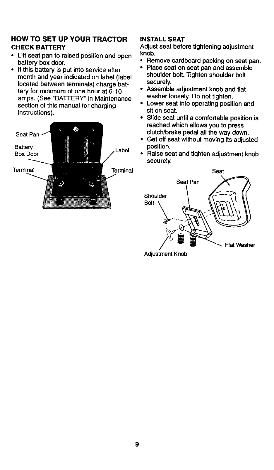
CHECK BATTERY
• Lift seat pan to raised position and open
battery box door,
• If this battery is put into service after
month and year indicated on label (label
located between terminals) charge bat-
tery for minimum of one hour at 6-10
amps. (See "BATTERY" in Maintenance
section of this manual for charging
instructions).
Seat Pan
Battery
Box Door
INSTALL SEAT
Adjust seat before tightening adjustment
knob.
• Remove cardboard packing on seat pan.
• P_ace seat on seat pan and assemble
shoulder bolt. Tighten shoulder bolt
securely,
• Assemble adjustment knob and flat
washer loosely. Do not tighten.
• Lower seat into operating position and
sit on seat.
• Slide seat until a comfortable position is
reached which allows you to press
clutch/brake pedal all the way down.
• Get off seat without moving its adjusted
position,
° Raise seat and tighten adjustment knob
securely.
Terminal Terminal Seat
Seat Pan
Shoulder
Bolt
Adjustment Knob
Flat Washer
9
CHECK TIRE PRESSURE
The tires on your tractor were overinflated
at the factory for shipping purposes.
Correct tire pressure is important for best
cutting performance.
• Reduce tire pressure to PSi shown in
"PRODUCT SPECIFICATIONS" section
of this manual.
CHECK DECK LEVELNESS
For best cutting results, mower housing
should be properly leveled. See "TO
LEVEL MOWER HOUSING" in the
Service and Adjustments section of this
manual.
CHECK FOR PROPER POSITION OF
ALL BELTS
See the figures that are shown for replac-
_otion and mower blade drive belts in
the Service and Adjustments sectoin of
this manual. Verify that the belts are rout-
ed correctly.
CHECK BRAKE SYSTEM
After you learn how to operate your trac-
tor, check to see that the brake is properly
adjusted. See "TO ADJUST BRAKE" in
the Service and Adjustments section of
this manual.
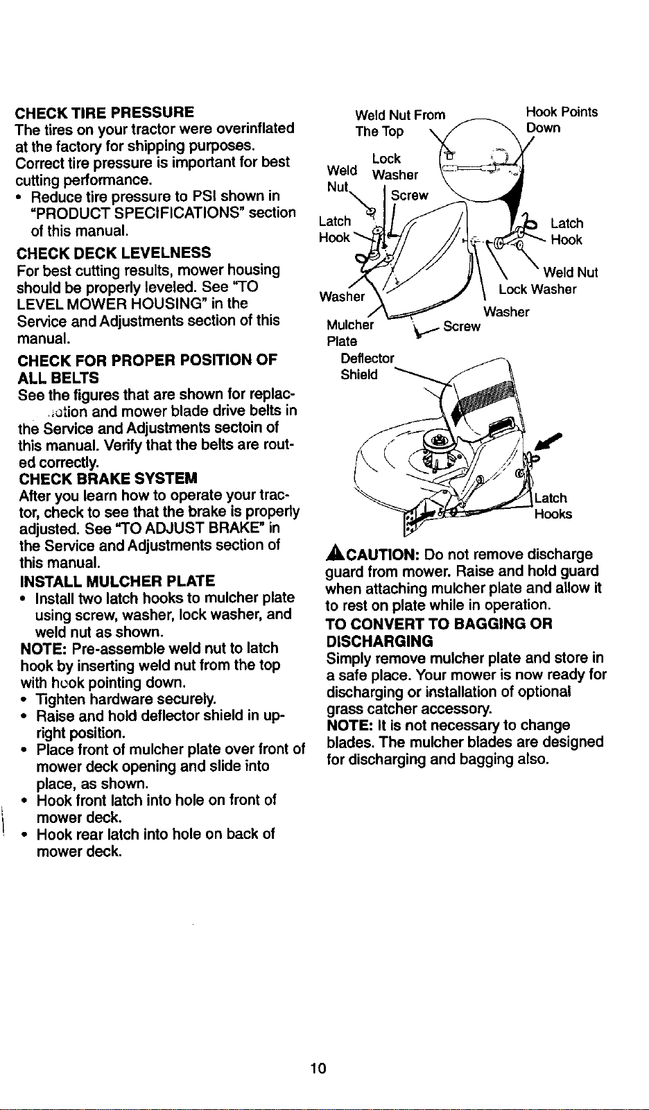
INSTALL MULCHER PLATE
• Install two latch hooks to mulcher plate
using screw, washer, lock washer, and
weld nut as shown.
NOTE: Pre-assemble weld nut to latch
hook by inserting weld nut from the top
with heok pointing down.
• "13ghtenhardware securely.
• Raise and hold deflector shield in up-
right position.
• Place front of mulcher plate over front of
mower deck opening and slide into
place, as shown.
• Hook front latch into hole on front of
mower deck.
• Hook rear latch into hole on back of
mower deck.
Weld Nut From
The Top
Lock
Weld Washer
Hook Points
Down
Latch
Latch
Hook
Washer
Mulcher
Plate
Deflector
| Nut
Lock Washer
Washer
'_./Screw
Shield
Latch
Hooks
ACAUTION: Do not remove discharge
guard from mower. Raise and hold guard
when attaching mulcher plate and allow it
to rest on plate while in operation.
TO CONVERT TO BAGGING OR
DISCHARGING
Simply remove mulcher plate and store in
a safe place. Your mower is now ready for
discharging or installation of optional
grass catcher accessory.
NOTE: It is not necessary to change
blades. The mulcher blades are designed
for discharging and bagging also.
10
v"CHECKLIST
Please review the following checklist:
•/ All assembly instructions have been
completed.
J" No remaining loose parts in carton.
,/Battery is properly prepared and
charged. (Minimum 1 hour at 6 amps).
4 Seat is adjusted comfortably and tight-
ened securely.
•/ All tires are properly inflated. (For ship-
ping purposes, the tires were overinflat-
ed at the factory).
,/Be sure mower deck is properly leveled
side-to-side/front-to-rear for best cutting
results. (Tires must be properly inflated
for leveling).
•/ Check mower and drive belts. Be sure
they are routed propedy around pulleys
and inside all belt keepers.
,/Check wiring. See that all connections
are still secure and wires are propedy
clamped.
While learning how to use your tractor, pay
extra attention to the following important
items:
,/Engine oil is at proper level.
,/Fuel tank is filled with fresh, clean, regu-
lar unleaded gasoline.
,/Become familiar with all controls - their
location and function. Operate them
before you start the engine.
•/ Be sure brake system is in safe operat-
ing condition.
11
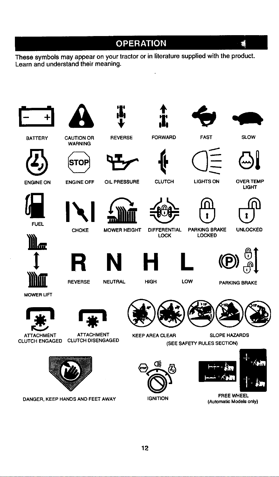
Thesesymbols may appear on your tractor or in literature supplied with the product.
Learn and understand their meaning.
BATTERY CAUTION OR REVERSE FORWARD FAST SLOW
WARNING
ENGINE ON ENGINE OFF OIL PRESSURE CLUTCH LIGHTS ON OVER TEMP
LIGHT
CHOKE MOWER HEIGHT DIFFERENTIAL PARKING BRAKE UNLOCKED
LOCK LOCKED
L
! R N H L
REVERSE NEUTRAL HIGH LOW PARKING BRAKE
MOWER LIFT
ATTACHMENT
CLUTCH ENGAGED CLUTCH DISENGAGED
ATTACHMENT KEEP AREA CLEAR SLOPE HAZARDS
(SEE SAFETY RULES SECTION)
DANGER, KEEP HANDS AND FEET AWAY
IGNITION FREE WHEEL
(Automatic Models only)
12
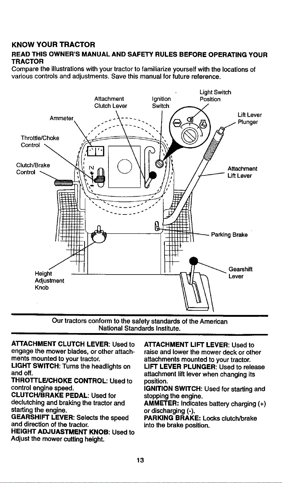
KNOW YOUR TRACTOR
READ THIS OWNER'S MANUAL AND SAFETY RULES BEFORE OPERATING YOUR
TRACTOR
Compare the illustrations with your tractor to familiarize yourself with the locations of
various controls and adjustments. Save this manual for future reference.
Attachment Ignition
Clutch Lever Switch
Light Switch
Position
LiftLever
Ammeter .... . Plunger
-.
Throttle/Choke
c.Z.
Control
Attachment
Lift Lever
Parking Brake
Height
Adjustment
Knob
Gearshift
Lever
Our tractors conform to the safety standards of the American
National Standards Institute,
ATTACHMENT CLUTCH LEVER: Used to
engage the mower blades, or other attach-
ments mounted to your tractor.
LIGHT SWITCH: Turns the headlights on
and off.
THROTTLE/CHOKE CONTROL: Used to
control engine speed.
CLUTCH/BRAKE PEDAL: Used for
declutching and braking the tractor and
starting the engine.
GEARSHIFT LEVER: Selects the speed
and direction of the tractor.
HEIGHT ADJUASTMENT KNOB: Used to
Adjust the mower cutting height.
ATTACHMENT LIFT LEVER: Used to
raise and lower the mower deck or other
attachments mounted to your tractor.
LIFT LEVER PLUNGER: Used to release
attachment lift lever when changing its
position.
IGNITION SWITCH: Used for starting and
stopping the engine.
AMMETER: Indicates battery charging (+)
or discharging (-).
PARKING BRAKE: Locks clutch/brake
into the brake position.
13
Theoperationofanytractorcan resultinforeignobjectsthrownintothe
eyes,whichcanresultinsevereeye damage. Always wear safety glasses
or eye shields while operating your tractor or performing any adjustments or
repairs. We recommend a wide vision safety mask over spectacles, or stan-
dard safety glasses.
HOW TO USE YOUR TRACTOR
Your tractor is equipped with an operator
presence sensing switch. When engine is
running, any attempt by the operator to
leave the seat without first setting the
parking brake will shut off the engine.
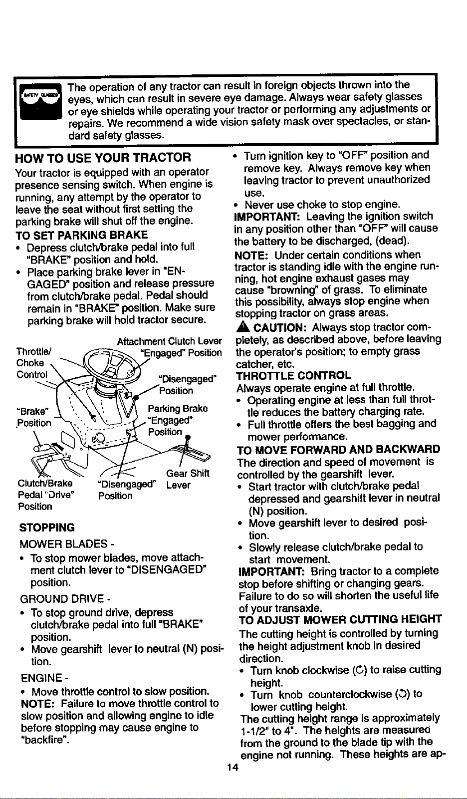
TO SET PARKING BRAKE
• Depress clutch/brake pedal into full
"BRAKE" position and hold.
• Place parking brake lever in "EN-
GAGED" position and release pressure
from clutch/brake pedal. Pedal should
remain in "BRAKE" position. Make sure
parking brake will hold tractor secure.
Throttle/
Choke
Control\
AttachmentClutch Lever
=Disengaged"
=Brake" Parking Brake
,Position . "Engaged"
Clutch/Brake =Disengaged"
Pedal "Odve" Position
Position
Gear Shift
Lever
STOPPING
MOWER BLADES -
• To stop mower blades, move attach-
ment clutch lever to "DISENGAGED"
position.
GROUND DRIVE -
• To stop ground drive, depress
clutch/brake pedal into full "BRAKE"
position.
• Move gearshift lever to neutral (N) posi-
tion.
ENGINE -
• Move throttle control to slow position.
NOTE: Failure to move throttle control to
slow position and allowing engine to idle
before stopping may cause engine to
"backfire".
• Turn ignition key to "OFF' position and
remove key. Always remove key when
leaving tractor to prevent unauthorized
use.
• Never use choke to stop engine.
IMPORTANT: Leaving the ignition switch
in any position other than "OFF" will cause
the battery to be discharged, (dead).
NOTE: Under certain conditions when
tractor is standing idle with the engine run-
ning, hot engine exhaust gases may
cause "browning _ of grass. To eliminate
this possibility, always stop engine when
stopping tractor on grass areas.
,_ CAUTION: Always stop tractor com-
pletely, as described above, before leaving
the operator's position; to empty grass
catcher, etc.
THROTTLE CONTROL
Always operate engine at full throttle.
• Operating engine at less than full throt-
tle reduces the battery charging rate.
• Full throttle offers the best bagging and
mower performance.
TO MOVE FORWARD AND BACKWARD
The direction and speed of movement is
controlled by the gearshift lever.
• Start tractor with clutch/brake pedal
depressed and gearshift lever in neutral
(N) position.
• Move gearshift lever to desired posi-
tion.
• Slowly release clutch/brake pedal to
start movement.
IMPORTANT: Bring tractor to a complete
stop before shifting or changing gears.
Failure to do so will shorten the useful life
of your transaxle.
TO ADJUST MOWER CUITING HEIGHT
The cutting height is controlled by turning
the height adjustment knob in desired
direction.
• Turn knob clockwise (G) to raise cutting
height.
• Turn knob counterclockwise (_) to
lower cutting height.
The cutting height range is approximately
1-1/2" to 4". The heights are measured
from the ground to the blade tip with the
engine not running. These heights are ap-
14
proximate and may vary depending upon
soil conditions, height of grass and types
of grass being mowed.
• The average lawn should be cut to
approximately 2-1/2 inches during the
cool season and to over 3 inches during
hot months. For healthier and better
looking lawns, mow often and after
moderate growth.
• For best cutting performance, grass
over 6 inches in height should be
mowed twice. Make the first cut rela-
tively high; the second to desired height.
TO ADJUST GAUGE WHEELS
Gauge wheels are properly adjusted
when they are slightly off the ground when
mower is at the desired cutting height in
operating position. Gauge wheels then
keep the deck in proper position to help
prevent scalping in most terrain condi-
tions.
• Adjust gauge wheels with tractor on a
flat level surface.
• Adjust mower to desired cutting height
(See "1"OADJUST MOWER CUTTING
HEIGHT" in the Operation section of
this manual).
• With mower in desired height of cut po-
sition, gauge wheels should be assem-
bled so they are slightly off the ground.
Install gauge wheel in appropriate hole
with shoulder bolt, 3/8 washer, and 3/8-
16 Iocknut and tighten securely.
• Repeat for opposite side installing
gauge wheel in same adjustment hole.
Gauge Wheel
Mounting
Bracket
3/8-16 Locknul
Shoulder
Gauge
TO OPERATE MOWER
Your tractor is equipped with an operator
presence sensing switch. Any attempt by
the operator to leave the seat with the
engine running and the attachment clutch
engaged will shut off the engine.
• Select desired height of cut.
• Lower mower with attachment lift con-
trol.
• Start mower blades by engaging attach-
ment clutch control.
• TO STOP MOWER BLADES - disen-
gage attachment clutch control.
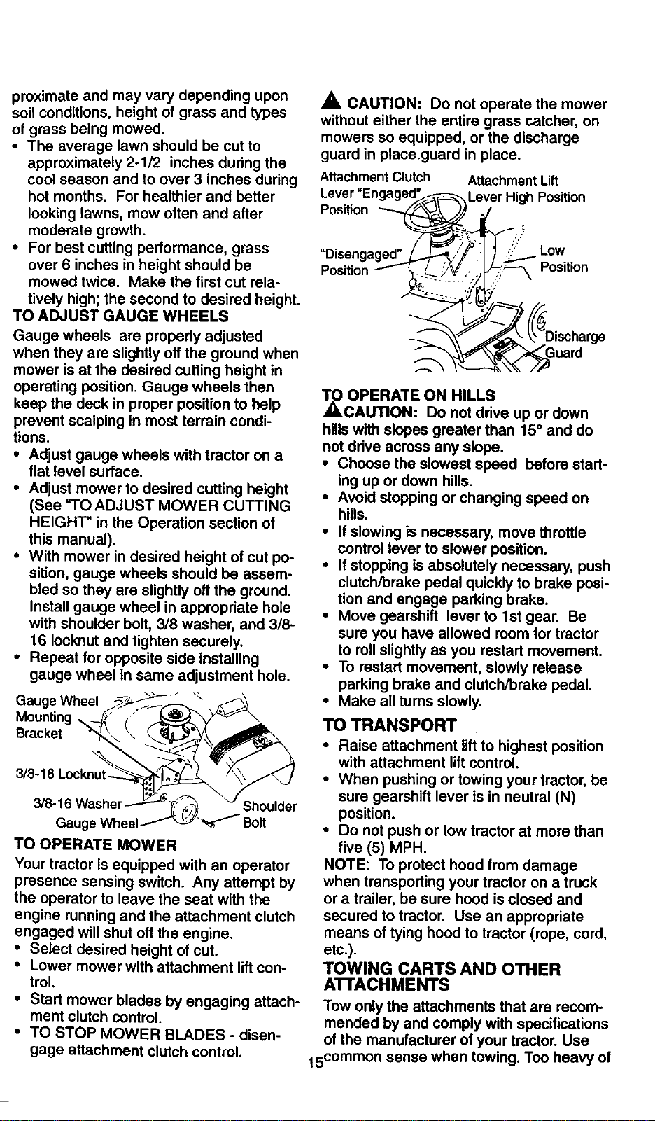
A CAUTION: Do not operate the mower
without either the entire grass catcher, on
mowers so equipped, or the discharge
guard in place.guard in place.
Attachment Clutch
Lever "En(
Position
Attachment Lift
Lever High Position
=Disengaged" Low
Position Position
TO OPERATE ON HILLS
ACAUTION: Do not drive up or down
hills with slopes greater than 15° and do
not drive across any slope.
• Choose the slowest speed before start-
ing up or down hills.
• Avoid stopping or changing speed on
hills.
• If slowing is necessary, move throttle
control lever to slower position.
• If stopping is absolutely necessary, push
clutch/brake pedal quickly to brake posi-
tion and engage parking brake.
• Move gearshift lever to 1st gear. Be
sure you have allowed room for tractor
to roll slightly as you restart movement.
• To restart movement, slowly release
parking brake and clutch/brake pedal.
• Make all turns slowly.
TO TRANSPORT
• Raise attachment lift to highest position
with attachment lift control.
• When pushing or towing your tractor, be
sure gearshift lever is in neutral (N)
position.
• Do not push or tow tractor at more than
five (5) MPH.
NOTE: To protect hood from damage
when transporting your tractor on a truck
or a trailer, be sure hood is closed and
secured to tractor. Use an appropriate
means of tying hood to tractor (rope, cord,
etc.).
TOWING CARTS AND OTHER
A'I-FACHMENTS
Tow only the attachments that are recom-
mended by and comply with specifications
of the manufacturer of your tractor. Use
15common sense when towing. Too heavy of
aload,whileonaslope,isdangerous.
Tirescanlosetraction with the ground and
cause you to lose control of your tractor.
BEFORE STARTING THE ENGINE
CHECK ENGINE OIL LEVEL
• The engine in your tractor has been
shipped, from the factory, already filled
with summer weight oil.
• Check engine oil with tractor on level
ground.
• Unthread and remove oil fill cap/dip-
stick; wipe oil off. Reinsert the dipstick
into the tube and rest oil fill cap on the
tube. Do not thread the cap onto the
tube. Remove and read oil level. If nec-
essary, add oil until "FULL" mark on
dipstick is reached. Do not overfill.
• For cold weather operation you should
change oil for easier starting (See "OIL
VISCOSITY CHART" in the Customer
Responsibilities section of this manual).
• To change engine oil, see the Customer
Responsibilities section in this manual.
ADD GASOUNE
• Fill fuel tank. Use fresh, clean, regular
unleaded gasoline with a minimum of 87
octane. (Use of leaded gasoline will
increase carbon and lead oxide
deposits and reduce valve life). Do not
mix oil with gasoline. Purchase fuel in
quantities that can be used within 30
days to assure fuel freshness.
IMPORTANT: When operating in tempera-
tures below 32°F(0°C), use fresh, clean
winter grade gasoline to help insure good
,_d weather starting.
WARNING: Experience indicates that
alcohol blended fuels (called gasohol or
using ethanol or methanol) can attract
moisture which leads to separation and
formation of acids during storage. Acidic
gas can damage the fuel system of an
engine while in storage. To avoid engine
problems, the fuel system should be emp-
tied before storage of 30 days or longer.
Drain the gas tank, start the engine and
let it run until the fuel lines and carburetor
are empty. Use fresh fuel next season.
See Storage Instructions for additional
information. Never use engine or carbure-
tor cleaner products in the fuel tank or per-
_nent damage may occur.
CAUTION: Fill to bottom of gas tank
filler neck. Do not overfill. Wipe off any
spilled oil or fuel. Do not store, spill or use
gasolir_e_ear an open.flame.
TO START ENGINE
When starting the engine for the first time
or ifthe engine has run out of fuel, it will
take extra cranking time to move fuel from
the tank to the engine.
• Sit on seat in operating position,
depress clutch/brake pedal and set
parking brake.
• Place gear shift lever in neutral (N) posi-
tion.
• Move attachment clutch to "DISEN-
GAGED" position.
• Move throttle control to choke position.
NOTE: Before starting, read the warm
and cold starting procedures below.
• Insert key into ignition and turn key
clockwise to "START" position and
release key as soon as engine starts.
Do not run starter continuously for more
than fifteen seconds per minute. If the
engine does not start after several
attempts, move throttle control to fast
position, wait a few minutes and try
again. If engine still does not start,
move the throttle control back to the
choke position and retry.
WARM WEATHER STARTING (50 ° F
AND ABOVE)
• When engine starts, move the throttle
control to the fast position.
• The attachments and ground drive can
now be used. If the engine does not
accept the load, restart the engine and
allow it to warm up for one minute using
the choke as described above.
COLD WEATHER STARTING ( 50 ° F
AND BELOW)
• When engine starts, allow engine to run
with the throttle control in the choke
position until the engine runs roughly,
then move throttle control to fast posi-
tion. This may require an engine warm-
up period from several seconds to sev-
eral minutes, depending on the temper-
ature.
• The attachments can also be used dur-
ing the engine warm-up period.
NOTE: If at a high altitude (above 3000
feet) or in cold temperatures (below 32 F)
the carburetor fuel mixture may need to be
adjusted for best engine performance.
See "TO ADJUST CARBURETOR" in the
Service and Adjustments section of this
manual.
16
MOWINGTiPS
• Tire chains cannot be used when the
mower housing is attached to tractor.
• Mower should be properly leveled for
best mowing performance. See "TO
LEVEL MOWER HOUSING" in the
Service and Adjustments section of this
manual.
• The left hand side of mower should be
used for trimming.
• Drive so that clippings are discharged
onto the area that has been cut. Have
the cut area to the right of the tractor.
This will result in a more even distribu-
tion of clippings and more uniform cut-
ting.
• When mowing large areas, start by turn-
ing to the right so that clippings will dis-
charge away from shrubs, fences, drive-
ways, etc. After one or two rounds, mow
in the opposite direction making left
hand turns until finished.
• If grass is extremely tall, it should be
mowed twice to reduce load and possi-
ble fire hazard from dried clippings.
Make first cut relatively high; the second
to the desired height.
• Do not mow grass when it is wet. Wet
grass will plug mower and leave unde-
sirable clumps. Allow grass to dry
before mowing.
• Always operate engine at full throttle
when mowing to assure better mowing
performance and proper discharge of
material. Regulate ground speed by se-
lecting a low enough gear to give the
mower the best cutting performance as
well as the quality of cut desired.
• When operating attachments, select a
ground speed that will suit the terrain
and give best performance of the at-
tachment being used.
MULCHING MOWING TIPS
IMPORTANT: For best performance, keep
mower housing free of built-up grass and
trash. Clean after each use.
• The special mulching blade will recut
the grass clippings many times and
reduce them in size so that as they fall
onto the lawn they will disperse into the
grass and not be noticed. Also, the
mulched grass will biodegrade quickly
to provide nutrients for the lawn. Always
mulch with your highest engine (blade)
speed as this will provide the best recut-
ting action of the blades.
• Avoid cutting your lawn when it is wet.
Wet grass tends to form clumps and
interferes with the mulching action. The
best time to mow your lawn is the early
afternoon. At this time the grass has
dried and the newly cut area will not be
exposed to the direct sun.
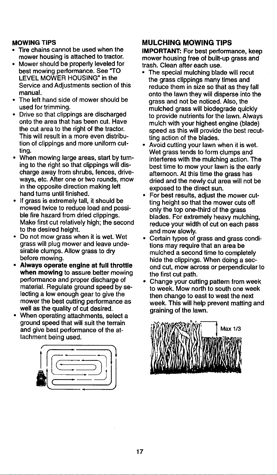
• For best results, adjust the mower cut-
ting height so that the mower cuts off
only the top one-third of the grass
blades. For extremely heavy mulching,
reduce your width of cut on each pass
and mow slowly.
• Certain types of grass and grass condi-
tions may require that an area be
mulched a second time to completely
hide the clippings. When doing a sec-
ond cut, mow across or perpendicular to
the first cut path.
• Change your cutting pattern from week
to week. Mow north to south one week
then change to east to west the next
week. This will help prevent matting and
graining of the lawn.
1/3
, ,
17
CUSTOMER RESPONSIBILITIES
.....
AsYouCOMPLETE
REGULAR SERVICE _'%_,_-,>_'z,_'fSERVICE DATES
Check Brake Operation
Check Tire Pressure _V' _
Check Operator Presence and
T Interlock Systems V'
R Check for Loose Fasteners I_ 1_7 V'
CA Sharpen/Replace Mower Blades _4
T Lubrication Chart I_
0 Check Battery Level
R Clean Battery and Terminals IkS
Check Transaxle Cooling Jl_
Adjust Blade Belt(s) Tension I_s
Adjust Motion Drive Belt(s) Tension I_s
Check Engine Oil Level V'
Change Engine Oil I_t,2,= I_
E Claan Air Filter _:
N Clean Air Screen
v'
G Inspect Muffler/Spark Arrester
Replace Oil Filter (If equipped) ._:
N Clean Engine Cooling Fins
Replace Spark Plug _
Replace Air Filter Paper Cartridge I_=
Replace Fuel Filter ll_
1 - Change more oftim when op_'ating undm" a heavy _ or in high anlblent temp_ltutes. 5 - I! oqu_ped with adjustable system.
2 - Son,ice more often when 0pe_if ng in dlrly or duety co_dlifons.
3 - If equipped with oil filter, change oiJevery 50 ho_$.
4 - Reface t_d_s more often when mowingin sandy soil
GENERAL RECOMMENDATIONS
The warranty on this tractor does not cover
items that have been subjected to operator
abuse or negligence. To receive full value
from the warranty, operator must maintain
tractor as instructed in this manual. Some
adjustments will need to be made periodi-
cally to properly maintain your tractor.
All adjustments in the Service and
Adjustments section of this manual should
be checked at least once each season.
• Once a year you should replace the
spark plug, clean or replace air filter, and
check blades and belts for wear. A new
spark plug and clean air filter assure
proper air-fuel mixture and help your
engine run better and last longer.
aEFORE EACH USE
Check engine oil level.
, Check brake operation.
• Check tire pressure.
• Check operator presence and interlock
systems for proper operation.
• Check for loose fasteners.
6 - Not r_lufrod if _ with maintenance-free batter/.
7 - Tighten front ax_ pivot bolt to 35 ft.-Ibs, maximum.
Do not overt_hten.
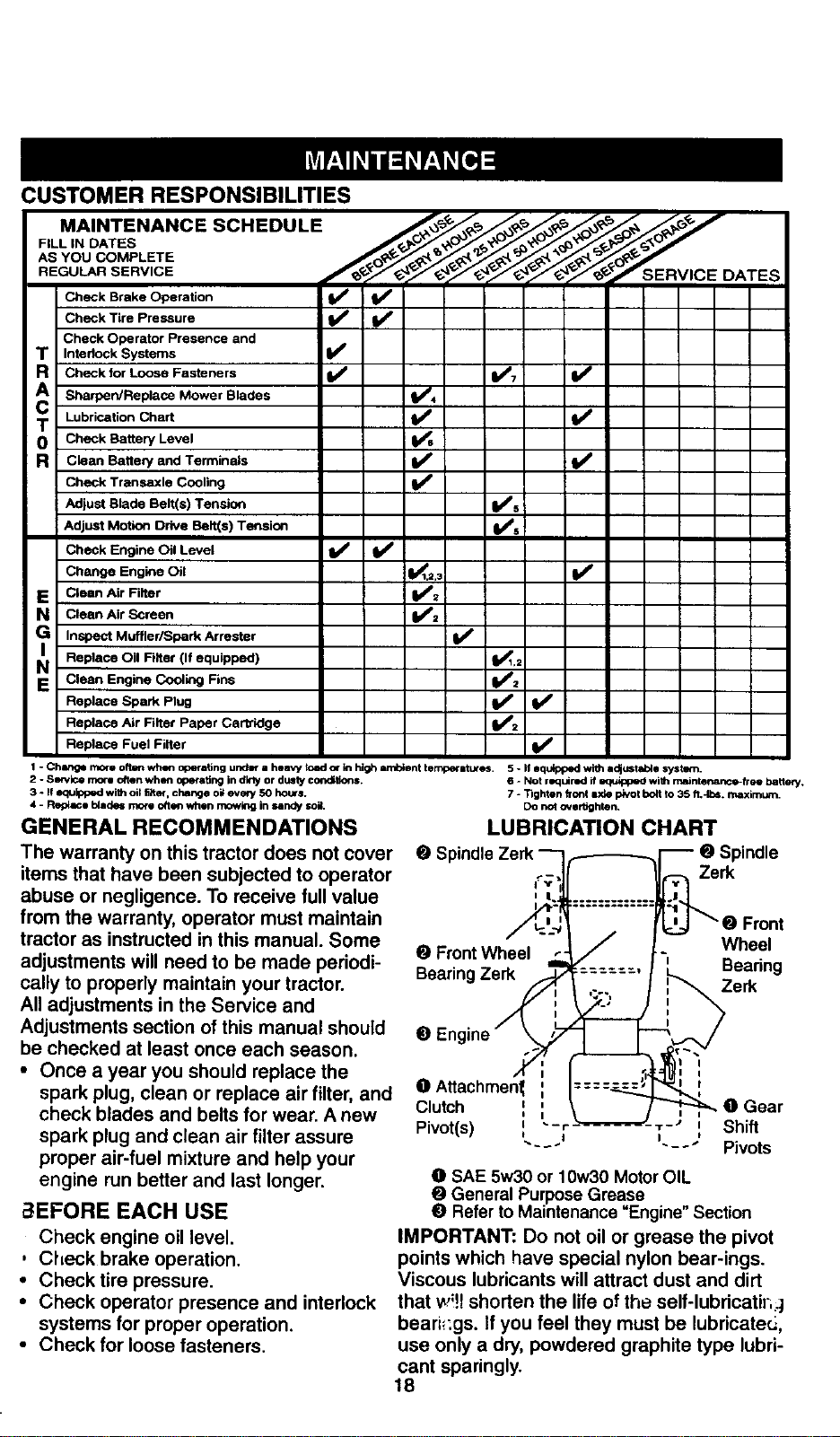
LUBRICATION CHART
_indle
Zerk
Front
O Front Wheel Wheel
BearingZerk Bearing
Zerk
O Engine
0 Gear
Shift
Pivots
O SAE 5w30 or 10w30 Motor OIL
O General Purpose Grease .
O Refer to Maintenance Engine Section
IMPORTANT: Do not oil or grease the pivot
points which have special nylon bear-ings.
Viscous lubricants will attract dust and dirt
that w!!I shorten the life of the self-lubricatil...]
beari_:gs. If you feel they must be lubricate_,
use only a dry, powdered graphite type lubri-
cant sparingly.
18
TRACTOR
Always observe safety rules when per-
forming any maintenance.
BRAKE OPERATION
If tractor requires more than six (6) feet
stopping distance at high speed in highest
gear, then brake must be adjusted. (See
"TO ADJUST BRAKE" in the Service and
Adjustments section of this manual).
TIRES
• Maintain proper air pressure in all tires
(See "PRODUCT SPECIFICATIONS"
section of this manual).
• Keep tires free of gasoline, oil, or insect
control chemicals which can harm rub-
ber.
• Avoid stumps, stones, deep ruts, sharp
objects and other hazards that may
cause tire damage.
NOTE: To seal tire punctures and prevent
flat tires due to slow leaks, tire sealant
may be purchased from your local parts
dealer. Tire sealant also prevents tire dry
rot and corrosion.
OPERATOR PRESENCE SYSTEM
Be sure that operator presence and inter-
lock systems are working properly. If your
tractor does not function as described
below, repair the problem immediately.
• The engine should not start unless the
clutch/brake pedal is fully depressed
and attachment clutch control is in the
disengaged position.
• When the engine is running, any
attempt by the operator to leave the
seat without first setting the parking
brake should shut off the engine.
• When the engine is running and the
attachment clutch is engaged, any
attempt by the operator to leave the
seat should shut off the engine.
• The attachment clutch should never
operate unless the operator is in the
seat.
BLADE CARE
For best results mower blades must be
kept sharp. Replace bent or damaged
blades.
BLADE REMOVAL
• Raise mower to highest position to allow
access to blades.
• Remove hex bolt, lock washer and flat
washer securing blade.
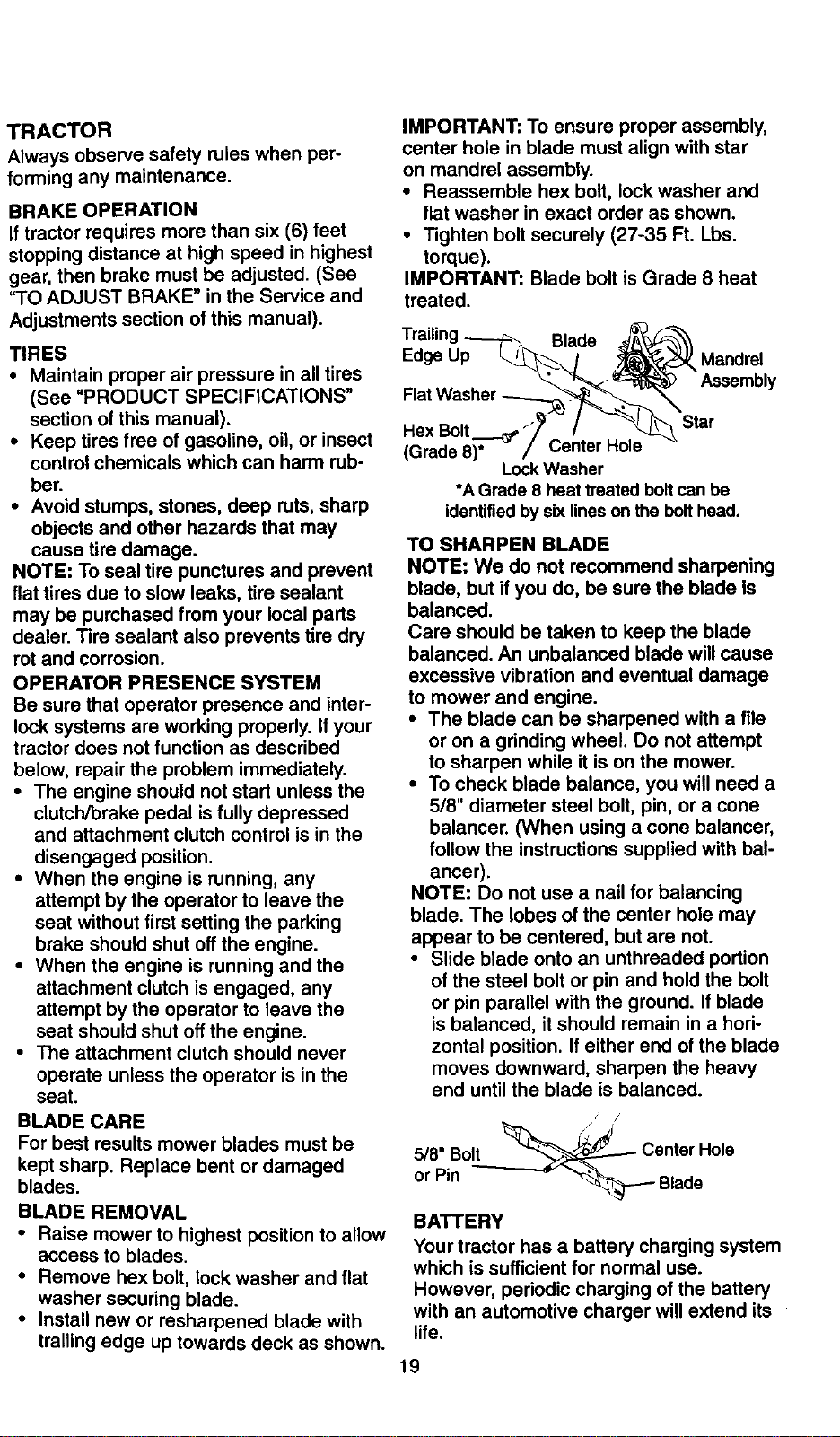
• Install new or resharpened blade with
trailing edge up towards deck as shown.
IMPORTANT: To ensure proper assembly,
center hole in blade must align with star
on mandrel assembly.
• Reassemble hex bolt, lock washer and
flat washer in exact order as shown.
• Tighten bolt securely (27-35 Ft. Lbs.
torque).
IMPORTANT: Blade bolt is Grade 8 heat
treated.
Trailing _ Blade __A-_
Edge Up _/ ,_ Mandrel
..... _L. _'_ -% Assembly
.ex
(Grade 8)* /_enmr _e
Lock Washer
*A Grade 8 heat treated bolt can be
identified by sixlines on the bolt head.
TO SHARPEN BLADE
NOTE: We do not recommend sharpening
blade, but if you do, be sure the blade is
balanced.
Care should be taken to keep the blade
balanced. An unbalanced blade will cause
excessive vibration and eventual damage
to mower and engine.
• The blade can be sharpened with a file
or on a grinding wheel. Do not attempt
to sharpen while it is on the mower.
• To check blade balance, you will need a
5/8" diameter steel bolt, pin, or a cone
balancer. (When using a cone balancer,
follow the instructions supplied with bal-
ancer).
NOTE: Do not use a nail for balancing
blade. The lobes of the center hole may
appear to be centered, but are not.
• Slide blade onto an unthreaded portion
of the steel bolt or pin and hold the bolt
or pin parallel with the ground. If blade
is balanced, it should remain in a hori-
zontal position. If either end of the blade
moves downward, sharpen the heavy
end until the blade is balanced.
• j
5/8" Bolt __ -_ Center Hole
or Pin - _Blade
BATTERY
Your tractor has a battery charging system
which is sufficient for normal use.
However, periodic charging of the battery
with an automotive charger will extend its
life.
19
• Keep battery bolts tight.
• Keep small vent holes open.
• Recharge at 6-10 amperes for I hour.
NOTE: The original equipment battery on
your tractor is maintenance free. Do not
attempt to open or remove caps or covers.
Adding or checking level of electrolyte is
not necessary.
TO CLEAN BATTERY AND TERMINALS
Corrosion and dirt on the battery and ter-
minals can cause the battery to "leak"
power.
: Open battery box door.
Disconnect BLACK battery cable first
then RED battery cable and remove
battery from tractor.
• Rinse the battery with plain water and
dry.
• Clean terminals and battery cable ends
with wire brush until bright.
• Coat terminals with grease or petroleum
jelllly..
• Reinstall battery (See REPLACING
BATTERY" in the SERVICE AND
ADJUSTMENTS section of this manu-
al).
V BELTS
Check V-belts for deterioration and wear
after 100 hours of operation and replace if
necessary. The belts are not adjustable.
Replace belts if they begin to slip from
wear.
TRANSAXLE COOLING
Keep transaxle free from build-up of dirt
and chaff which can restrict cooling.
ENGINE
LUBRICATION
Only use high quality detergent oil rated
with API service classification SF, SG, or
SH. Select the oil's SAE viscosity grade
according to your expected operating tem-
perature.
Change the oil after every 50 hours of
operation or at least once a year if the
tractor is not used for 50 hours in one
year.
Check the crankcase oil level before start-
ing the engine and after each eight (8)
hours of operatron. Tighten oil fill cap/dip-
stick securely each time you check the oil
level.
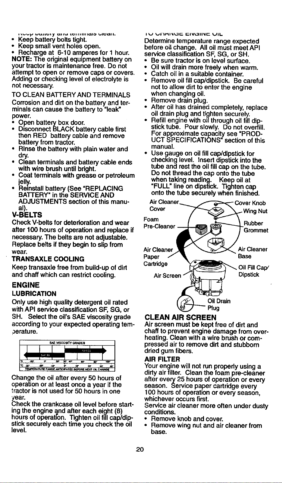
ll_/ _,lrl/-i,l_l_lr__ [_l_l_711_lr-- Ull..
Determine temperature range expected
before oil change. All oil must meet API
service classification SF, SG, or SH.
• Be sure tractor is on level surface.
Oil will drain more freely when warm.
Catch oil in a suitable container.
• Remove oil fill cap/dipstick. Be careful
not to allow dirt to enter the engine
when changing oil.
Remove drain plug.,
•" After oil has drainea completely, replace
oil drain plug and tighten securely,
• Refill engine with oil through oil fill dip-
stick tube. Pour slowly. Do not overfill.
For approximate capacity see "PROD-
UCT SPECIFICATIONS" section of this
manual.
• Use gauge on oil fill cap/dipstick for
checking level. Insert dipstick into the
tube and rest the oil fill cap on the tube.
Do not thread the cap onto the tube
when taking reading. Keep oil at
"FULL" line on dipstick. Tighten cap
onto the tube securely when finished.
Cover Nut
Foam Rubber
Air Cleaner Air Cleaner
Paper Base
Cartridge Fill Cap/
Dipstick
Oil Drain
Plug
CLEAN AIR SCREEN
Air screen must be kept free of dirt and
chaff to prevent engine damage from over-
heating. Clean with a wire brush or com-
pressed air to remove dirt and stubborn
dried gum fibers.
AIR FILTER
Your engine will not run properly using a
dirty air filter. Clean the foam pre-cleaner
after every 25 hours of operation or every
season. Service paper cartridge every
100 hours of operation or every season,
whichever occurs first.
Service air cleaner more often under dusty
conditions.
• Remove knob and cover.
• Remove wing nut and air cleaner from
base.
20
TO SERVICE PRE-CLEANER
Slide foam pre-cleaner off cartridge.
i Wash it in liquid detergent and water.
Squeeze it dry in a clean cloth. Allow it
to dry.
• Saturate it in engine oil. Wrap it in
clean, absorbent cloth and squeeze to
remove excess oil.
TO SERVICE CARTRIDGE
• Replace a dirty, bent, or damaged car-
tridge.
NOTE: Do not wash the paper cartridge
or use pressurized air, as this will damage
the cartridge.
• Reinstall the pre-cleaner (cleaned and
oiled) over the paper cartridge.
• Reassemble air cleaner, wing nut, cover
and tighten knob securely.
CLEAN AIR INTAKE/COOLING AREAS
To insure proper cooling, make sure the
grass screen, cooling fins, and other
external surfaces of the engine are kept
clean at all times.
Every 100 hours of operation (more often
under extremely dusty, dirty conditions),
remove the blower housing and other
cooling shrouds. Clean the cooling fins
and external surfaces as necessary. Make
sure the cooling shrouds are reinstalled.
NOTE: Operating the engine with a
blocked grass screen, dirty or plugged
cooling fins, and/or cooling shrouds re-
moved will cause engine damage due to
overheating.
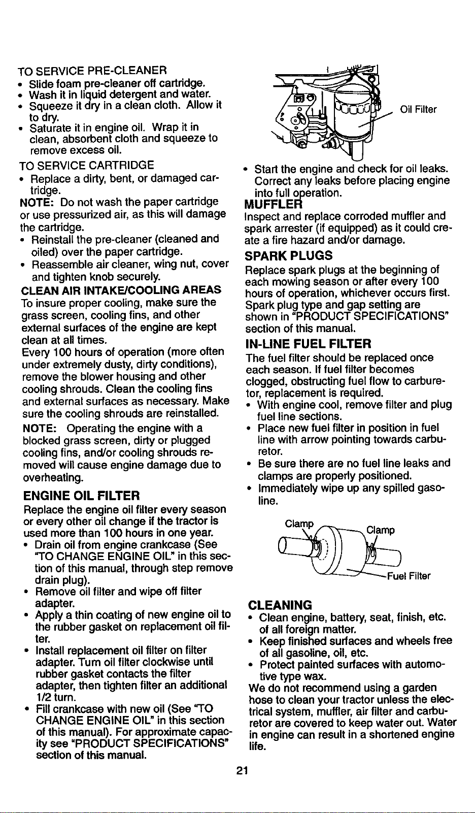
ENGINE OIL FILTER
Replace the engine oil filter every season
or every other oil change if the tractor is
used more than 100 hours in one year.
• Drain oil from engine crankcase (See
"TO CHANGE ENGINE OIL" in this sec-
tion of this manual, through step remove
drain plug).
• Remove oil filter and wipe off filter
adapter.
• Apply a thin coating of new engine oil to
the rubber gasket on replacement oil fil-
ter.
• Install replacement oil filter on filter
adapter. Turn oil filter clockwise until
rubber gasket contacts the filter
adapter, then tighten filter an additional
1/2 turn.
• RII crankcase with new oil (See "TO
CHANGE ENGINE OIL" in this section
of this manual). For approximate capac-
ity see "PRODUCT SPECIFICATIONS"
section of this manual.
Oil Filter
• Start the engine and check for oil leaks.
Correct any leaks before placing engine
into full operation.
MUFFLER
Inspect and replace corroded muffler and
spark arrester (if equipped) as it could cre-
ate a fire hazard and/or damage.
SPARK PLUGS
Replace spark plugs at the beginning of
each mowing season or after every 100
hours of operation, whichever occurs first.
Spark plug type and gap setting are
shown in "PRODUCT SPECIFICATIONS"
section of this manual.
IN-LINE FUEL FILTER
The fuel filter should be replaced once
each season. If fuel filter becomes
clogged, obstructing fuel flow to carbure-
tor, replacement is required.
• With engine cool, remove filter and plug
fuel line sections.
• Place new fuel filter in position in fuel
line with arrow pointing towards carbu-
retor.
• Be sure there are no fuel line leaks and
clamps are properly positioned.
• Immediately wipe up any spilled gaso-
line.
Filter
CLEANING
• Clean engine, battery, seat, finish, etc.
of all foreign matter.
• Keep finished surfaces and wheels free
of all gasoline, oil, etc.
• Protect painted surfaces with automo-
tive type wax.
We do not recommend using a garden
hose to clean your tractor unless the elec-
trical system, muffler, air filter and carbu-
retor are covered to keep water out. Water
in engine can result in a shortened engine
life.
21
,_CAUTION: Before performing any service or adjustments:
• Depress clutch/brake pedal fully and set parking brake.
• Place gearshift lever in neutral (N) position.
• Place attachment clutch in "DISENGAGED" position.
• Turn ignition key "OFF" and remove key.
• Make sure the blades and all moving parts have completely stopped.
• Disconnect spark plug wire from spark plug and place wire where it cannot come
in contact with plug.
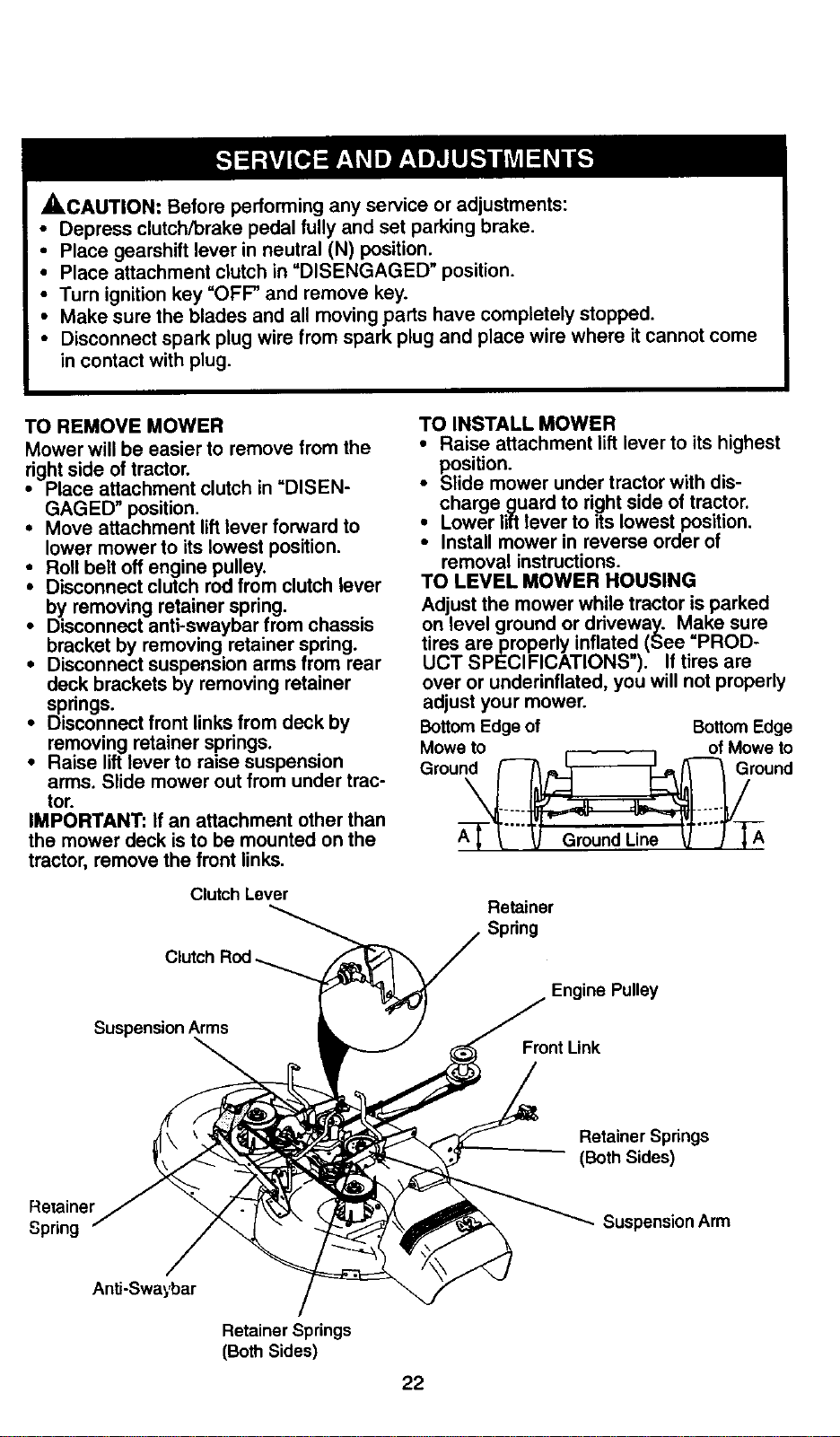
TO REMOVE MOWER
Mower will be easier to remove from the
right side of tractor.
• Place attachment clutch in "DISEN-
GAGED" position.
• Move attachment lift lever forward to
lower mower to its lowest position.
• Roll belt off engine pulley.
Disconnect clutch rod from clutch lever
by removing retainer spring.
• Disconnect anti-swaybar from chassis
bracket by removing retainer spring.
• Disconnect suspension arms from rear
deck brackets by removing retainer
springs.
• Disconnect front links from deck by
removing retainer springs.
• Raise lift lever to raise suspension
arms. Slide mower out from under trac-
tor.
IMPORTANT: If an attachment other than
the mower deck is to be mounted on the
tractor, remove the front links.
Clutch Lever
TO INSTALL MOWER
• Raise attachment lift lever to its highest
position.
• Slide mower under tractor with dis-
charge guard to right side of tractor.
• Lower lift lever to its lowest position.
• Install mower in reverse order of
removal instructions.
TO LEVEL MOWER HOUSING
Adjust the mower while tractor is parked
on level ground or driveway. Make sure
tires areproperly inflated (See "PROD-
UCT SPECIFICATIONS"). If tires are
over or underinflated, you will not properly
adjust your mower.
BottomEdge of Bottom Edge
Mowe to of Mowe to
A---[TL'"_ GroundLine _-"J--_
Retainer
Spdng
SuspensionArms
Engine Pulley
Front Link
Retainer Springs
(Both Sides)
Re_ainer
Spring
Suspension Arm
Anti-Swa_,,bar
Retainer Springs
(BothSides)
22
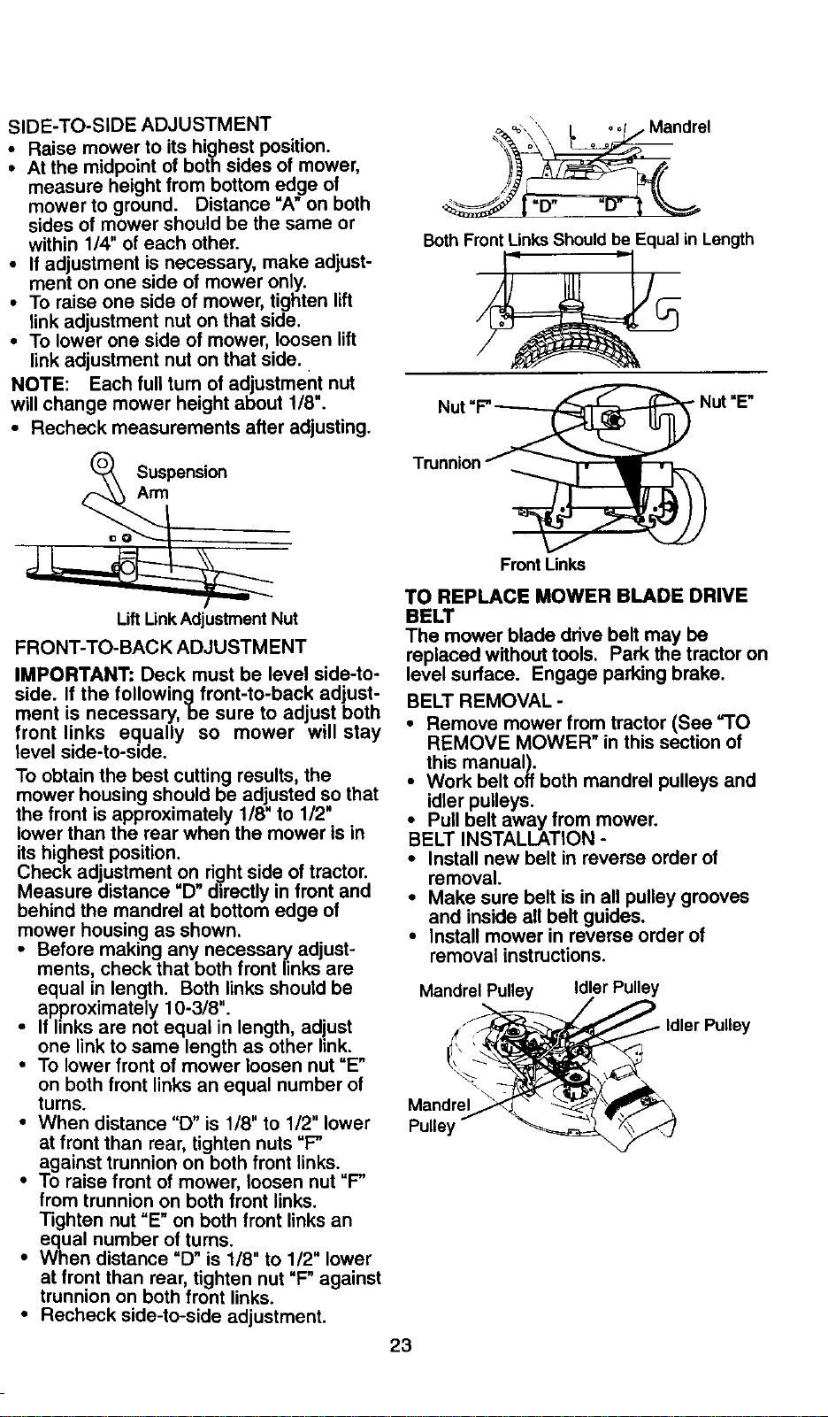
SIDE-TO-SIDE ADJUSTMENT
• Raise mower to its highest position.
• At the midpoint of both sides of mower,
measure height from bottom edge of
mower to ground. Distance "A" on both
sides of mower should be the same or
within 1/4" of each other.
• If adjustment is necessary, make adjust-
ment on one side of mower only.
• To raise one side of mower, tighten lift
link adjustment nut on that side.
• To lower one side of mower, loosen lift
link adjustment nut on that side.
NOTE: Each full turn of adjustment nut
will change mower height about 1/8".
• Recheck measurements after adjusting.
Suspension
Arm
Lift LinkAdjustment Nut
FRONT-TO-BACK ADJUSTMENT
IMPORTANT: Deck must be level side-to-
side. If the followingfront-to-back adjust-
ment is necessary, be sure to adjust both
front links equally so mower will stay
level side-to-side.
To obtain the best cutting results, the
mower housing should be adjusted so that
the front is approximately 1/8" to 1/2"
lower than the rear when the mower is in
its highest position.
Check adjustment on ri._ht side of tractor.
Measure distance =D" directly in front and
behind the mandrel at bottom edge of
mower housing as shown.
• Before making any necessary adjust-
ments, check that both front links are
equal in length. Both links should be
approximately 10-3/8".
• If links are not equal in length, adjust
one link to same length as other link.
• To lower front of mower loosen nut "E"
on both front links an equal number of
turns.
• When distance "D" is 1/8" to 1/2" lower
at front than rear, tighten nuts "F"
against trunnion on both front links.,
• To raise front of mower, loosen nut F"
from trunnion on both front links.
Tighten nut "E" on both front links an
equal number of turns.
• When distance "D" is 1/8" to 1/2" lower
at front than rear, tighten nut "F" against
trunnion on both front links.
• Recheck side-to-side adjustment.
\
_%oo,,\'\L 001/ Mandrel
_'N o o o
Both Front LinksShould be Equal in Length
Nut "F"_ _Nut "E"
Tmnnion_ _ _
L-
Front Links
TO REPLACE MOWER BLADE DRIVE
BELT
The mower blade drive belt may be
replaced without tools. Park the tractor on
level surface. Engage parking brake.
BELT REMOVAL -
• Remove mower from tractor (See "TO
REMOVE MOWER" in this section of
this manual).
• Work belt off both mandrel pulleys and
idler pulleys.
• Pull belt away from mower.
BELT INSTALLATION -
• Install new belt in reverse order of
removal.
• Make sure belt is in all pulley grooves
and inside all belt guides,
• Install mower in reverse order of
removal instructions.
Mandrel Pulley Idler Pulley
Mandrel
Pulley
Idler Pulley
23
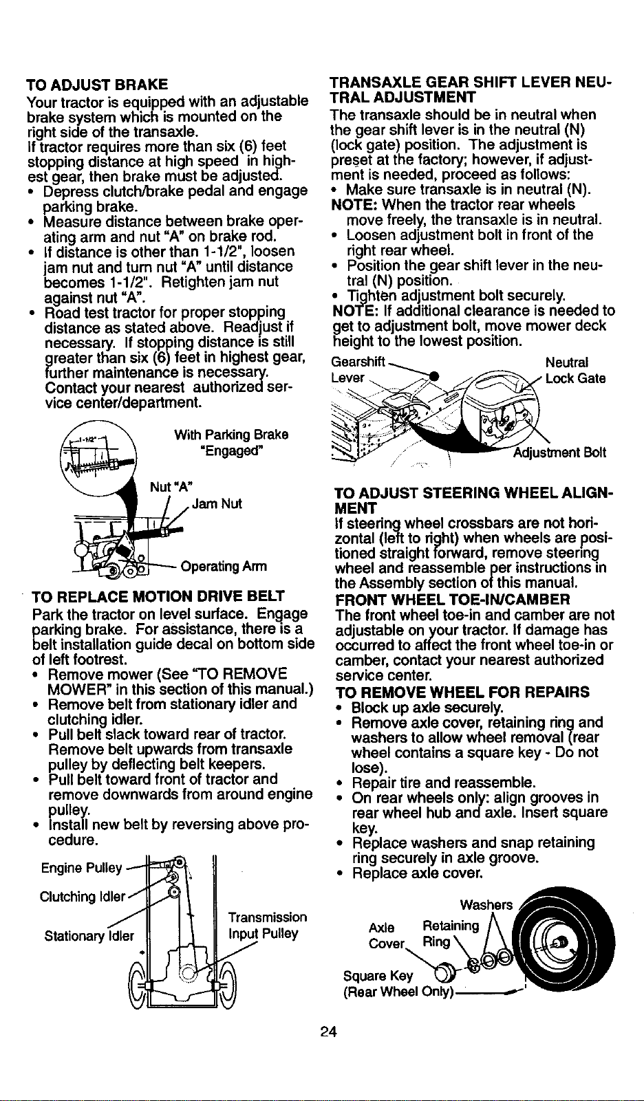
TOADJUSTBRAKE
Yourtractorisequippedwithanadjustable
brakesystemwhichismountedon the
rightsideofthetransaxle.
Iftractorrequiresmorethansix(6)feet
stoppingdistanceathighspeed inhigh-
estgear,thenbrakemustbeadjusted.
• Depress clutch/brake pedal and engage
parking brake.
• Measure distance between brake oper-
ating arm and nut "A" on brake rod.
• If distance is other than 1-1/2", loosen
jam nut and tum nut "A" until distance
becomes 1-1/2". Retightenjam nut
against nut "A".
• Road test tractor for proper stopping
distance as stated above. Readjust if
necessary. If stopping distance is still
greater than six (6) feet in highest gear,
further maintenance is necessary.
Contact your nearest authofizedser-
vice center/department.
With Parking Brake
"Engaged"
TRANSAXLE GEAR SHIFT LEVER NEU-
TRAL ADJUSTMENT
The transaxle should be in neutral when
the gear shift lever is in the neutral (N)
(lock gate) position. The adjustment is
preset at the factory; however, if adjust-
ment is needed, proceed as follows:
• Make sure transaxle is in neutral (N).
NOTE: When the tractor rear wheels
move freely, the transaxle is in neutral.
• Loosen adjustment bolt in front of the
right rear wheel.
• Position the gear shift lever in the neu-
tral (N) position.
• Tighten adjustment bolt securely.
NOTE: If additional clearance is needed to
get to adjustment bolt, move mower deck
height to the lowest position.
Leyer_
Neutral
Lock Gate
Nut"A"
Jam Nut
Arm
• TO REPLACE MOTION DRIVE BELT
Park the tractor on level surface. Engage
parking brake. For assistance, there is a
belt installation guide decal on bottom side
of left footrest.
• Remove mower (See =TO REMOVE
MOWER" in this section of this manual.)
• Remove belt from stationary idler and
clutching idler.
• Pull belt slack toward rear of tractor.
Remove belt upwards from transaxle
pulley by deflecting belt keepers.
• Pull belt toward front of tractor and
remove downwards from around engine
pulley.
• Install new belt by reversing above pro-
cedure.
Engine Pulley
Clutching Idler J
Stationary Idler
4
Y
Transmission
Input Pulley
TO ADJUST STEERING WHEEL ALIGN-
MENT
if steeringwheel crossbars are not hori-
zontal (left to fight) when wheels are posi-
tioned straight forward, remove steering
wheel and reassemble per instructionsin
the Assembly section ot this manual.
FRONT WHEEL TOE-IN/CAMBER
The front wheel toe-in and camber are not
adjustable on your tractor. If damage has
occurred to affect the front wheel toe-in or
camber, contact your nearest authorized
service center.
TO REMOVE WHEEL FOR REPAIRS
• Block up axle securely.
• Remove axle cover, retaining ring and
washers to allow wheel removal (rear
wheel contains a square key - Do not
lose).
• Repair tire and reassemble.
• On rear wheels only: align grooves in
rear wheel hub andaxle. Insert square
key.
• Replace washers and snap retaining
ring securely in axle groove.
• Replace axle cover.
24
NOTE: To seal tire punctures and prevent
flat tires due to slow leaks, tire sealant
may be purchased from your local parts
dealer. Tire sealant also prevents tire dry
rot and corrosion.
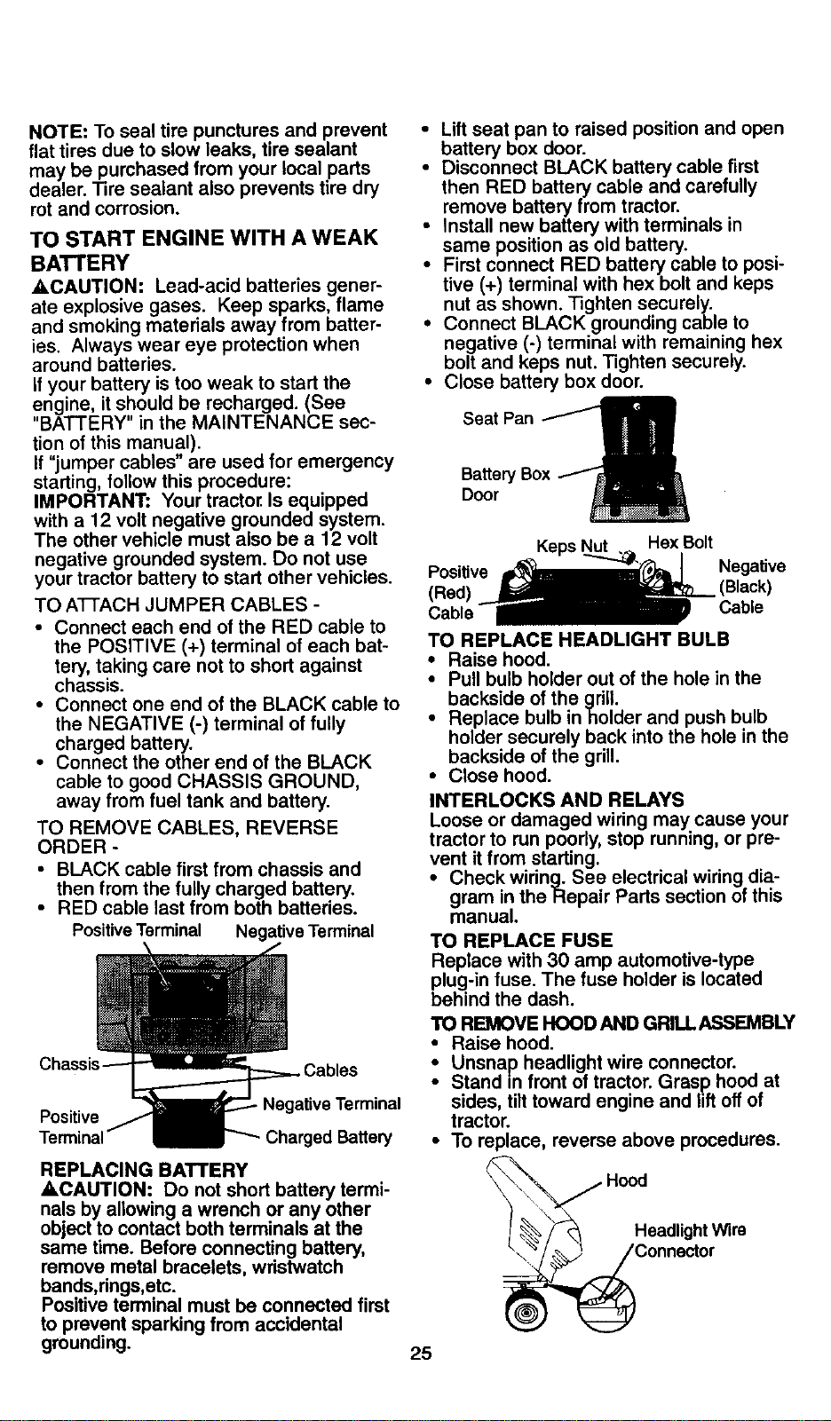
TO START ENGINE WITH A WEAK
BATTERY
A, CAUTION: Lead-acid batteries gener-
ate explosive gases. Keep sparks, flame
and smoking materials away from batter-
ies. Always wear eye protection when
around batteries.
If your battery is too weak to start the
engine, it should be recharged. (See
"BATTERY" in the MAINTENANCE sec-
tion of this manual).
If "jumper cables" are used for emergency
starting, follow this procedure:
IMPORTANT: Your tractor Is equipped
with a 12 volt negative grounded system.
The other vehicle must also be a 12 volt
negative grounded system. Do not use
your tractor battery to start other vehicles.
TO ATTACH JUMPER CABLES -
• Connect each end of the RED cable to
the POSITIVE (+) terminal of each bat-
tery, taking care not to short against
chassis.
• Connect one end of the BLACK cable to
the NEGATIVE (-) terminal of fully
charged battery.
• Connect the other end of the BLACK
cable to good CHASSIS GROUND,
away from fuel tank and battery.
TO REMOVE CABLES, REVERSE
ORDER -
• BLACK cable first from chassis and
then from the fully charged battery.
• RED cable last from both batteries.
PositiveTerminal Negative Terminal
Positive
,rminal
Charged Battery
REPLACING BATTERY
ACAUTION: Do not short battery termi-
nals by allowing a wrench or any other
object to contact both terminals at the
same time. Before connecting battery,
remove metal bracelets, wristwatch
bands,rings, etc.
Positive terminal must be connected first
to prevent sparking from accidental
grounding.
• Lift seat pan to raised position and open
battery box door.
• Disconnect BLACK battery cable first
then RED battery cable and carefully
remove battery from tractor.
• Install new battery with terminals in
same position as old battery.
• First connect RED battery cable to posi-
tive (+) terminal with hex bolt and keps
nut as shown. Tighten securely.
• Connect BLACK grounding cable to
negative (-) terminal with remaining hex
bolt and keps nut. Tighten securely.
• Close battery box door.
Seat Pan
Bakery Box
Door
25
Keps _ Hex Bolt
Positive Negative
(Red) (Black)
Cable Cable
TO REPLACE HEADLIGHT BULB
• Raise hood.
• Pull bulb holder out of the hole in the
backside of the grill.
• Replace bulb inholder and push bulb
holder securely back into the hole in the
backside of the grill.
• Close hood.
INTERLOCKS AND RELAYS
Loose or damaged wiring may cause your
tractor to run poorly, stop running, or pre-
vent it from starting.
• Check wiring. See electrical wiring dia-
gram in the Repair Parts section of this
manual.
TO REPLACE FUSE
Replace with 30 amp automotive-type
plug-in fuse. The fuse holder is located
behind the dash.
TO REMOVE HOOD AND GRILL ASSEMBLY
• Raise hood.
• Unsnap headlight wire connector.
Stand m front of tractor. Grasp hood at
sides, tilt toward engine and lift off of
tractor.
• To replace, reverse above procedures.
Connector
ENGINE
Maintenance,repair,or replacementofthe
emissioncontroldevicesandsystems,
whicharebeingdoneatthecustomers
expense,maybeperformedbyanynon-
roadenginerepairestablishmentorindi-
vidual.Warrantyrepairsmustbe per-
formedbyan authorizedenginemanufac-
turer's service outlet.
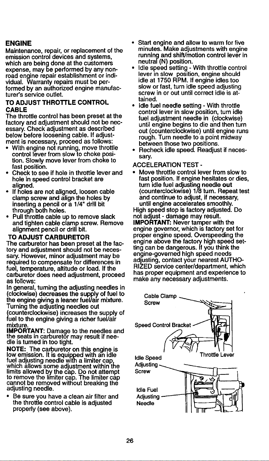
TO ADJUST THROTrLE CONTROL
CABLE
The throttle control has been preset at the
factory and adjustment should not be nec-
essary. Check adjustment as described
below before loosening cable. If adjust-
ment is necessary, proceed as follows:
• With engine not running, move throttle
control lever from slow to choke posi-
tion. Slowly move lever from choke to
fast position.
• Check to see if hole in throttle lever and
hole in speed control bracket are
aligned.
• If holes are not aligned, loosen cable
clamp screw and align the holes by
inserting a pencil or a 1/4" drill bit
through beth holes.
• Pull throttle cable up to remove slack
and tighten cable clamp screw. Remove
alignment pencil or dril/bit.
TO ADJUST CARBURETOR
The carburetor has been preset at the fac-
tory and adjustment should not be neces-
sary. However, minor adjustment may be
required to compensate for differences in
fuel, temperature, altitude or load. If the
carburetor does need adjustment, proceed
as follows:
In general, turning the adjusting needles in
(clockwise) decreases the supply of fuel to
the engine giving a leaner fuel/air mixture.
Turning the adjusting needles out
(countemleckwise) increases the supply of
fuel to the engine giving a richer fuel/air
mixture.
IMPORTANT: Damage to the needles and
the seats in careuretor may result if nee-
dle is turned in too tight.
NOTE: The carburetor on this engine is
low emission. It is _.equippedwith an idle
fuel adjusting needle with a limiter cap,
wnicn allows some adjustment within the
limits allowed by the cap. Do not attempt
to remove the limiter cap. The limiter cap
cannot be removed without breaking the
adjusting needle.
• Be sure you have a clean air filter and
the throttle control cable is adjusted
properly (see above).
• Start engine and allow to warm for five
minutes. Make adjustments with engine
running and shift/motion control lever in
neutral (N) position.
• Idle speed setting - With throttle control
lever in slow position, engine should
idle at 1750 RPM. If engine idles too
slow or fast, turn idle speed adjusting
screw in or out until correct idle is at-
tained.
• Idle fuel needle setting - With throttle
control lever in slow position, turn idle
fuel adjustment needle in (clockwise)
until engine begins to die and then turn
out (counterclockwise) until engine runs
rough. Turn needle to a point midway
between those two positions.
• Recheck idle speed. Readjust if neces-
sary.
ACCELERATION TEST -
• Move throttle control lever from slow to
fast position. If engine hesitates or dies,
turn idle fuel adjusting needle out
(countemlockwise) 118 turn. Repeat test
and continue to adjust, if necessary,
until engine accelerates smoothly.
High speed stop is factory adjusted. Do
not adjust - damage may result.
IMPORTANT: Never tamper with the
engine governor, which is factory set for
proper engine speed. Overspeeding the
engine above the factory high speed set-
ting can be dangerous. If you think the
engine-governed high speed needs
adjusting, contact your nearest AUTHO-
RIZED service center/department, which
has proper equipment and experience to
make any necessary adjustments.
Cable Clamp
Screw
Speed Control
Idle Speed
Screw
Throttle Lever
Idle Fuel
Adjusting
Needle
26
Immediatelyprepareyourtractorforstor-
ageattheendoftheseasonorifthetrac-
torwillnot be used for 30 days or more.
_,CAUTION: Never store the tractor with
gasoline in the tank inside a building
where fumes may reach an open flame or
spark. Allow the engine to cool before
storing in any enclosure.
TRACTOR
Remove mower from tractor for winter
storage. This will allow you to clean itthor-
oughly. Remove all dirt, grease, leaves,
etc. Store in a clean, dry area.
• Clean entire tractor (See =CLEANING"
in the Maintenance section of this man-
ual).
• Inspect and replace belts, if necessary
(See belt replacement instructions in the
Service and Adjustments section of this
manual).
• Lubricate as shown in the Maintenance
section of this manual.
• Be sure that all nuts, bolts and screws
are securely fastened. Inspect moving
parts for damage, breakage and wear.
Replace if necessary.
• Touch up all rusted or chipped paint sur-
faces; sand lightly before painting.
BATTERY
• Fully charge the battery for storage.
• After a period of time in storage, battery
may require recharging.
• To help prevent corrosion and power
leakage during long pedods of storage,
battery cables should be disconnected
and battery cleaned thoroughly (see
"TO CLEAN BATTERY AND TERMI-
NALS" in the Maintenance section of
this manual).
• After cleaning, leave cables disconnect-
ed and place cables where they cannot
come in contact with battery terminals.
• If battery is removed from tractor for
storage, do not store battery directly on
concrete or damp surfaces.
ENGINE
FUEL SYSTEM
IMPORTANT: It is important to prevent
gum deposits from forming in essential
fuel system parts such as carburetor, fuel
filter, fuel hose, or tank during storage.
Also, experience indicates that alcohol
blended fuels (called gasohol or using
ethanol or methanol) can attract moisture
which leads to separation and formation of
acids during storage. Acidic gas can dam-
age the fuel system of an engine while in
storage.
• Drain the fuel tank.
• Start the engine and let it run until the
fuel lines and carburetor are empty.
• Never use engine or carburetor cleaner
products in the fuel tank or permanent
damage may occur.
• Use fresh fuel next season.
NOTE: Fuel stabilizer is an acceptable
alternative in minimizing the formation of
fuel gum deposits during storage. Add sta-
bilizer to gasoline in fuel tank or storage
container. Always follow the mix ratio
found on stabilizer container. Run engine
at least 10 minutes after adding stabilizer
to allow the stabilizer to reach the carbure-
tor. Do not drain the gas tank and carbure-
tor if using fuel stabilizer.
ENGINE OIL
Drain oil (with engine warm) and replace
with clean engine oil. (See =ENGINE" in
the Maintenance section of this manual).
CYLINDER(S)
• Remove spark plug(s).
• Pour one ounce of oil through spark
plug hole(s) into cylinder(s).
• Turn ignition key to "START" position for
a few seconds to distribute oil.
• Replace with new spark plug(s).
OTHER
• Do not store gasoline from one season
to another.
• Replace your gasoline can if it starts to
rust. Rust and/or dirt in your gasoline
will cause problems.
• If possible, store your tractor indoors
and cover it to give protection from dust
and dirt.
• Cover your tractor with a suitable pro-
tective cover that does not retain mois-
ture. Do not use plastic. Plastic cannot
breathe, which allows condensation to
form and cause your tractor to rust.
IMPORTANT: Never cover tractor while
engine and exhaust areas are still warm.
27
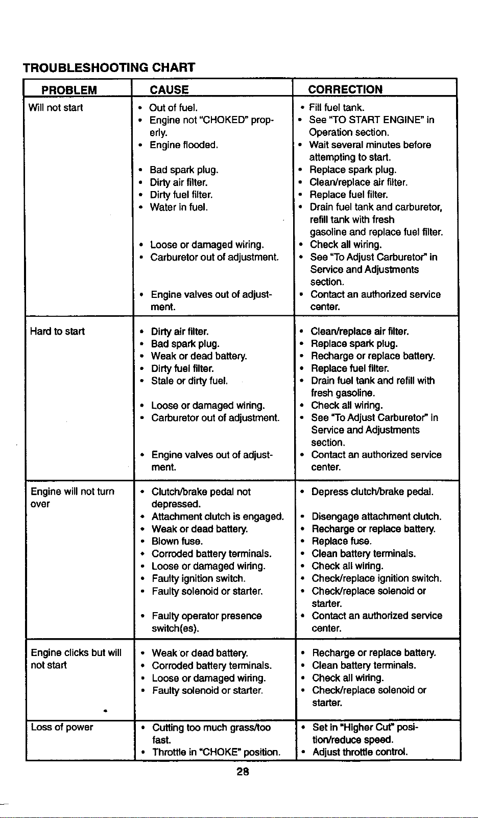
TROUBLESHOOTING CHART
PROBLEM
Will not start
Hard to start
Engine will not turn
over
Engine clicksbut will
not start
Loss of power
CAUSE
• Out of fuel.
• Engine not"CHOKED" prop-
erly.
• Engine flooded.
• Bad spark plug.
• Dirtyair filter.
• Dirtyfuel filter.
• Water in fuel.
• Loose or damaged wiring.
• Carburetor out of adjustment.
• Engine valves out of adjust-
ment.
• Dirtyair tilter.
• Bad spark plug.
• Weak or dead battery.
• Dirtyfuel filter.
• Stale or dirtyfuel,
• Loose or damaged wiring.
• Carburetor out of adjustment.
• Engine valves out of adjust-
ment.
• Clutch/brake pedal not
depressed.
• Attachment clutchisengaged.
• Weak or dead battery.
• Blownfuse.
• Corroded batteryterminals.
• Loose or damaged wiring,
• Faulty ignitionswitch.
• Faultysolenoid or starter,
• Faultyoperator presence
switch(es).
• Weak or dead battery.
• Corroded battery terminals.
• Loose or damaged wiring.
• Faulty solenoid or starter,
• Cuttingtoo much grass/too
fast.
• Throttle in =CHOKE" position.
28
CORRECTION
• Fillfuel tank.
• See "TO START ENGINE" in
Operation section.
' • Wait several minutes before
attempting to start.
• Replace spark plug.
• Clean/replace air filter.
• Replace fuel filter.
• Drain fuel tank and carburetor,
refill tank with fresh
gasoline and replace fuel filter.
• Check all wiring.
• See "To Adjust Carburetor" in
Service and Adjustments
section.
• Contact an authorized service
center.
• Clean/replace air filter.
• Replace spark plug.
• Recharge or replace battery.
• Replace fuel filter.
• Drain fuel tank and refillwith
fresh gasoline.
• Check all wiring.
• See "ro Adjust Carburator"in
Service and Adjustments
section.
• Contact an authorized service
center.
• Depress clutch/brake pedal.
• Disengage attachment clutch.
• Recharge or replace battery.
• Replace fuse,
• Clean battery terminals.
• Check all wiring.
• Check/replace ignitionswitch.
• Check/replace solenoid or
starter.
• Contact an authorized service
center.
• Recharge or replace battery.
• Clean battery terminals.
• Check all wiring.
• Check/replace solenoidor
starter.
• Set in "Higher Cut" posi-
fion/reduce speed.
• Adjust throttle control.
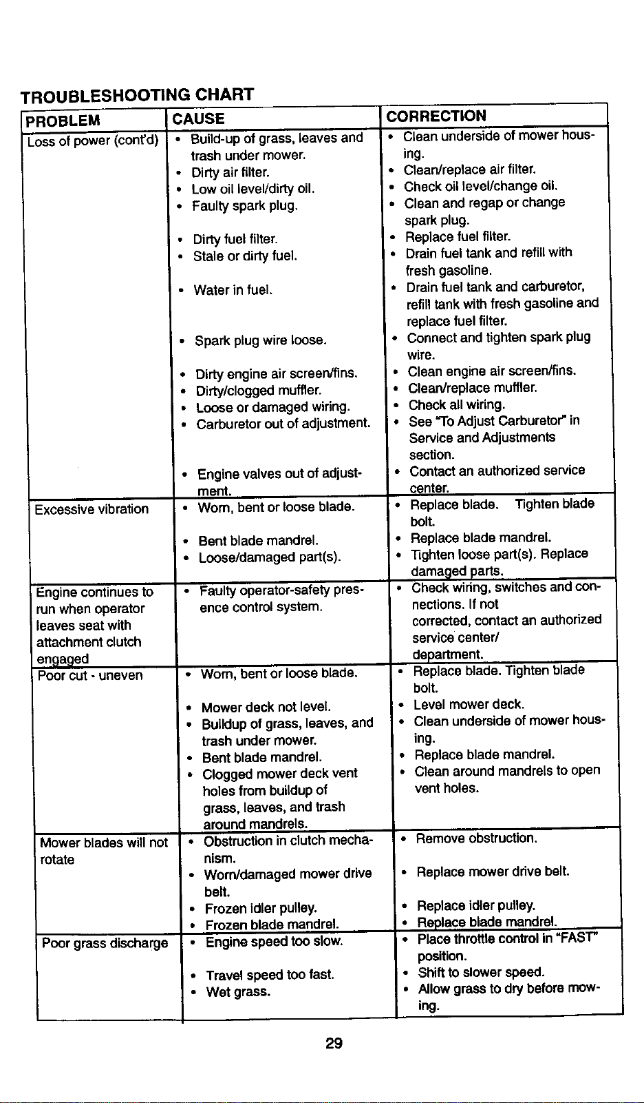
}ROBLEM
Lossof power (cont'd)
TROUBLESHOOTING CHART
CAUSE
• Build-up of grass, leaves and
trash under mower.
• Dirtyair filter.
• Low oil level/dirty oil.
• Faulty spark plug.
Excessive vibration
Engine continues to
runwhen operator
leaves seat with
attachment clutch
engaged
Poor cut - uneven
Mower blades will not
rotate
Poor grass discharge
Dirty fuel filter.
• Stale or dirty fuel.
• Water in fuel.
• Spark plug wire loose.
• Dirtyengine air screen/fins.
• Dirty/clogged muffler.
• Loose or damaged wiring.
• Carburetor out of adjustment.
• Engine valves out of adjust-
ment.
• Worn, bent or loose blade.
• Bent blade mandrel.
• Loose/damaged part(s).
• Faulty operator-safety pres-
ence controlsystem.
• Worn, bent or loose blade.
• Mower deck not level,
• Buildupof grass,leaves, and
trash under mower.
• Bent blade mandrel.
• Clogged mower deck vent
holesfrom buildupof
grass, leaves, and trash
around mandrels.
• Obstructionin clutch mecha-
nism.
• Worn/damaged mower drive
belt.
• Frozen idler pulley.
• Frozen blade mandrel.
• Engine speed too slow.
• Travel speed too fast.
• Wet grass.
CORRECTION
• Clean underside of mower hous-
ing.
• Clean/replace air filter.
• Check oillevel/change oil.
• Clean and regap or change
spark plug.
• Replace fuel filter.
• Drain fuel tank and refillwith
fresh gasoline.
Io Drain fuel tank and carburetor,
refill tank with fresh gasoline and
replace fuel filter.
• Connect and tighten spark plug
wire.
• Clean engine airscraen/fins,
• Clean/replace muffler.
• Check all wiring.
• See "ToAdjust Carburetor"in
Service and Adjustments
section.
• ContaCtan authorized service
center.
• Replace blade. Tightenblade
bolt.
• Replace blade mandrel.
• Tighten loose part(s). Replace
damaged parts.
• Check wiring, switches and con-
nections. If not
corrected, contactan authorized
service center/
department.
• Replace blade. Tighten blade
bolt.
• Level mower deck.
• Clean underside of mower hous-
ing.
• Replace blade mandrel.
• Clean around mandrels toopen
vent holes.
• Remove obstruction.
• Replace mower drive belt.
• Replace idler pulley.
=• Replace blade mandrel.
io Place throttlecontrolin "FAST"
position.
Shift to slower speed.
Allow grass to dry before mow-
ing.
29
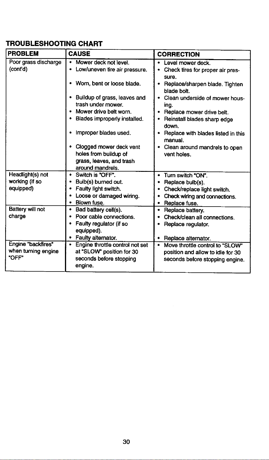
TROUBLESHOOTING CHART
PROBLEM CAUSE
Poorgrass discharge • Mower deck not level.
(cont'd) • Low/uneven tire air pressure.
•Wom, bent or looseblade.
• Buildupofgrass, leaves and
trash under mower.
• Mower drive belt worn.
• Blades improperlyinstalled.
• Improper blades used.
Headlight(s) not
working(ifso •
equipped) •
Battery willnot •
charge
Engine "backfires" i-
when turning engine
"OFP
Clogged mower deck vent
holesfrom buildupof
grass, leaves, and trash
around mandrels.
Switch is"OFP.
Bulb(s) burned out.
Faultylight switch.
Loose or damaged wiring.
Blownfuse.
Bad battery cell(s).
Poorcable connections,
Faultyregulator (if so
equipped).
Faultyaltemator.
Engine throttlecontrolnot set
at "SLOW" positionfor 30
seconds before stopping
engine,
CORRECTION
• Level mower deck.
• Check tires for properair pres-
sure.
• Replace/sharpen blade, "5ghten
blade bolt,
• Clean underside of mower hous-
ing.
• Replace mower drivebelt.
• Reinstallblades sharp edge
down.
• Replace with blades listed inthis
manual.
• Clean around mandrels to open
vent holes.
• Turn switch"ON".
• Replace bulb(s).
• Check/replace light switch.
• Check widngandconnections.
• Replace fuse.
• Replace battery,
• Check/clean all connections.
• Replace regulator.
Replace alternator.
Move throttle controlto "SLOW"
position and allow to idlefor 30
seconds before stopping engine.
3O
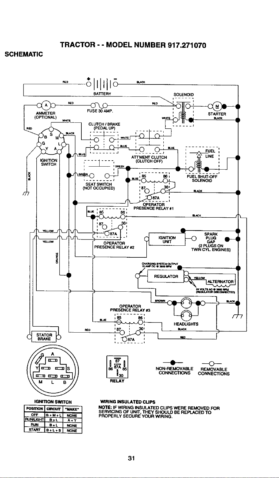
SCHEMATIC
TRACTOR - " MODEL NUMBER 917.271070
fll_D
SOLE.NOlO
BAI"FERY
_P,
AMMETER
(OPTIONAL)
CLUTCH / BRAKE
........ s
t ........ J
SEAT SWITCH
(NOT OCCUPIED)
IGNmON SWITCH
OFF G,_*M-_L NONE
RUN B*L NONE ,
START B+L*S NONE
i
--- , UNE ,
ATT'MENT CLUTCH
L (CLUTCH i II
FUEL SHUT-OFF
SOLENOID
' SPARK
IGNITION PLUG
UNIT GAP
OPERATOR (2 PLUGS ON
HELAY #2 TWIN CYL ENGINES)
NON-REMOVABLE REMOVABLE
CONNECTIONS CONNECTIONS
RELAY
WIRING INSULATED CLIPS
NOTE: IF WIRING INSULATED CLIPS WERE REMOVED FOR
SERVICING OF UNIT. THEY SHOULD BEREPLACED TO
pROPERLY SECURE YOUR WIRING.
31
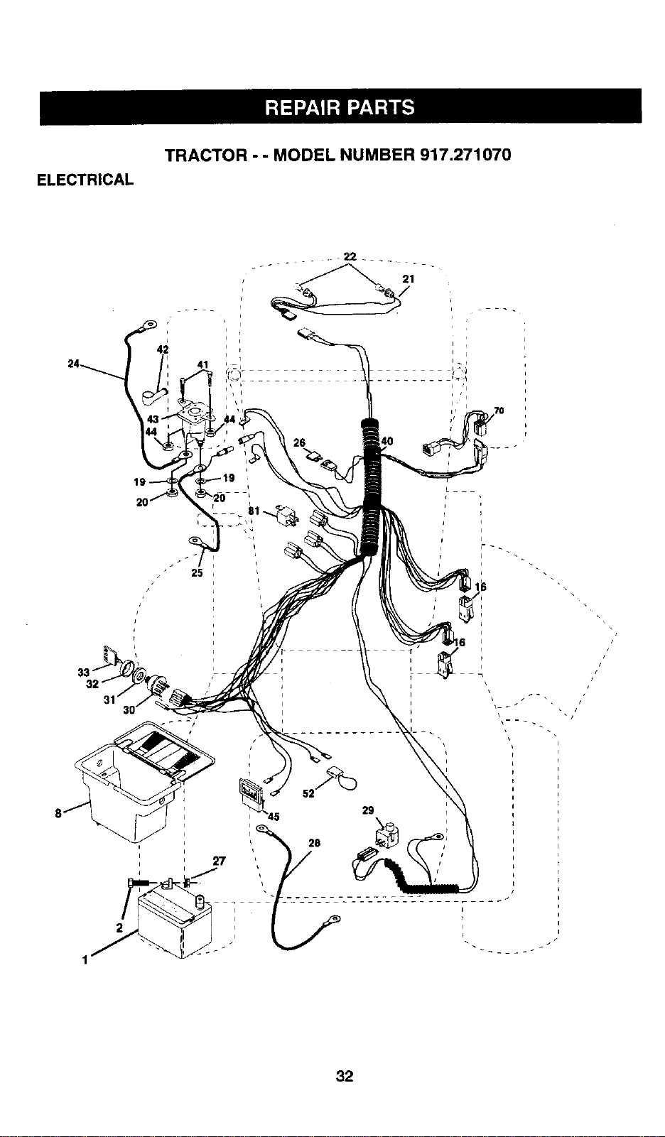
ELECTRICAL
TRACTOR - - MODEL NUMBER 917.271070
,i
24 41
• 22 ....
21
I i
i
i
I t
i
7O
32
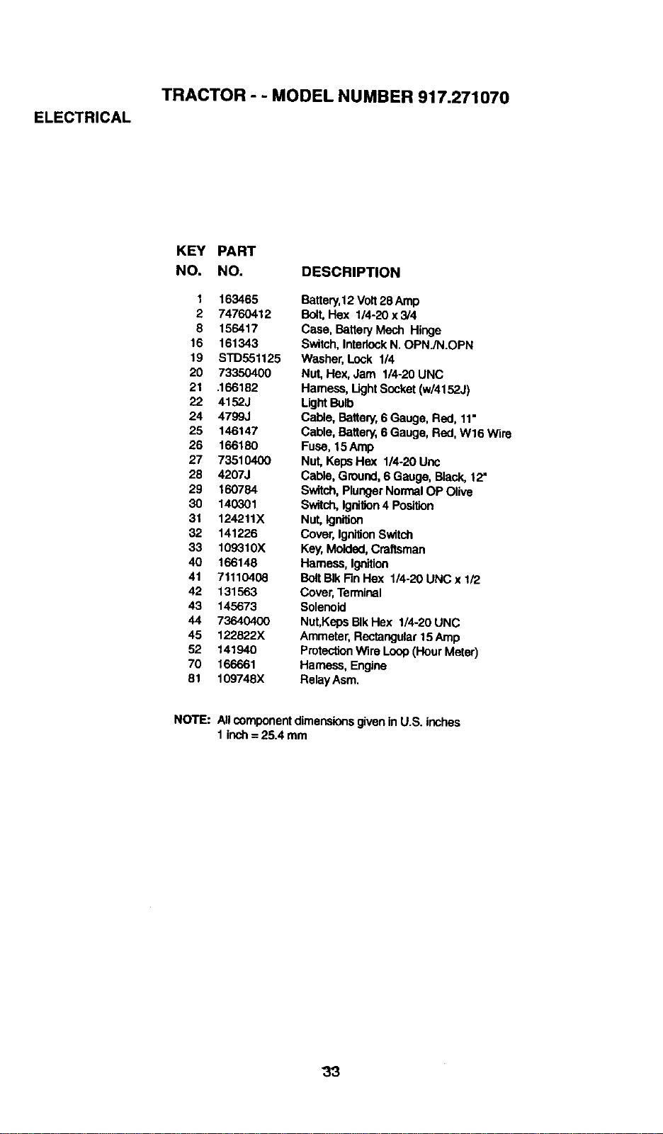
ELECTRICAL
TRACTOR - - MODEL NUMBER 917.271070
KEY PART
NO. NO. DESCRIPTION
1 163465
2 74760412
8 156417
16 161343
19 STD551125
20 73350400
21 .166182
22 41523
24 4799J
25 146147
26 166180
27 73510400
28 4207J
29 160784
30 140301
31 124,211X
32 141226
33 109310X
40 166148
41 7_110408
42 131563
43 145673
44 73640400
45 122622X
52 141940
70 166661
81 109748)(
Battery,12Volt28 Amp
Bolt,Hex 1/4-20 x 3/4
Case, Battery Mech Hinge
Switch,InterlockN. OPN./N.OPN
Washer, Lock 114
Nut, Hex, Jam 114-20UNC
Harness, LightSocket(w/4152J)
L_J_ B_b
Cable, Battery,6 Gauge, Red, 11"
Cable, Battery,6 Gauge, Red, W16 Wire
Fuse, 15Amp
Nut,KepsHex 1/4-20 Uric
Cable, Ground,6 Gauge, Black, 12"
Switch,PlungerNormalOP Olive
Sw_tch,Ignition4 Position
Nut,kjnition
Cover,IgnitionSwitch
Key,Molded,Craftsman
Harness,Ignition
B_t Blk Fin Hex 114-20UNC x 1/2
Cover,Terminal
Solenoid
Nut,KepsBIkHex 1/4-20 UNC
Ammeter,Reetang_tar15Amp
Protection Wire Loop(Hour Meter)
Hamass, Engine
Relay Asm.
NOTE: AllcomponentdimensionsgiveninU.S. inches
1 inch= 25.4 mm
33
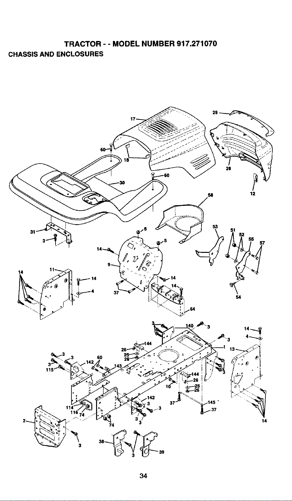
TRACTOR - - MODEL NUMBER 917.271070
CHASSIS AND ENCLOSURES
31
60
53
S4
55
111161
/3
3
74 3
38_ 39
14
34
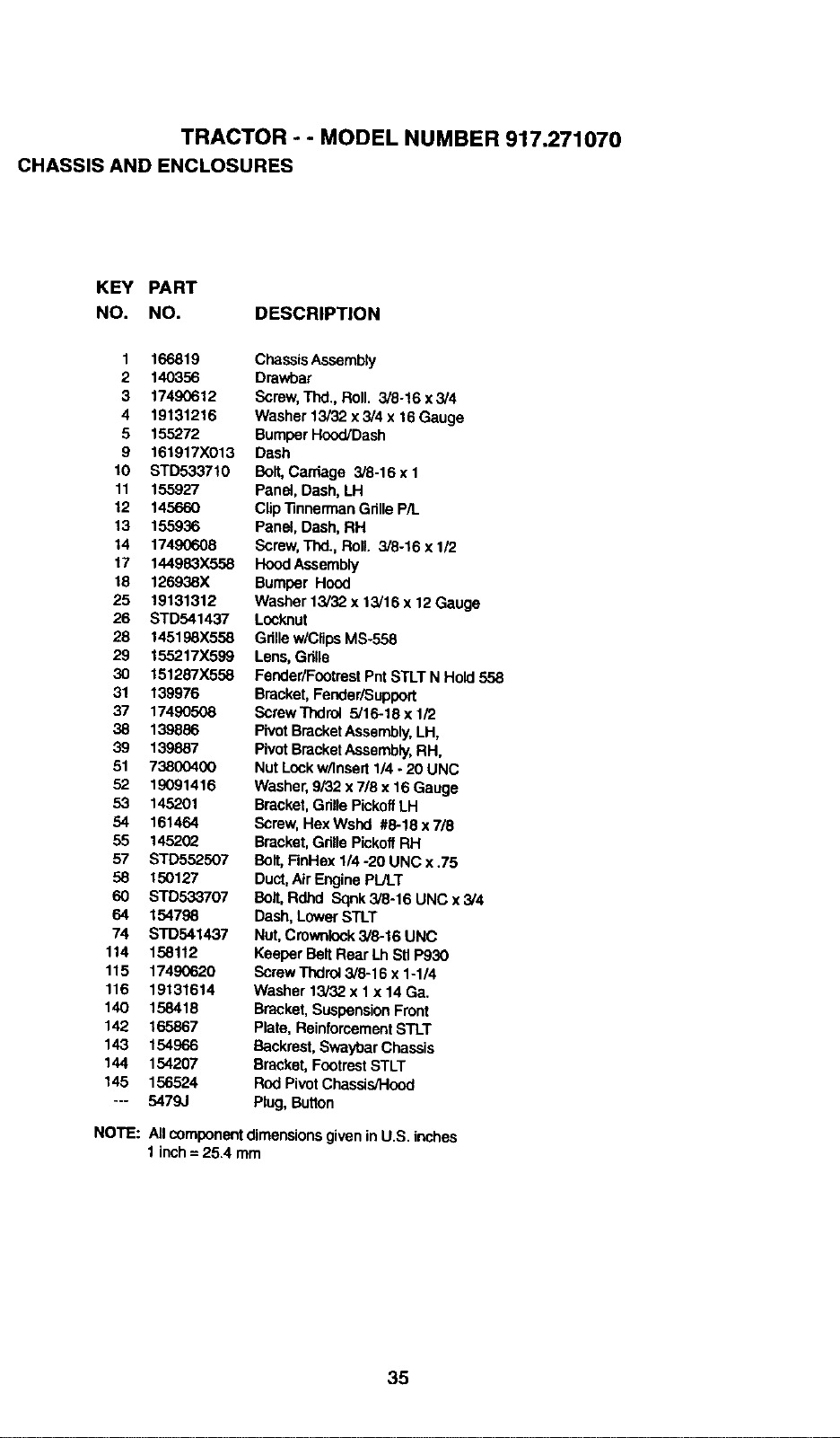
TRACTOR - - MODEL NUMBER 917.271070
CHASSIS AND ENCLOSURES
KEY PART
NO. NO. DESCRIPTION
1 166819
2 140356
3 17490612
4 19131216
5 155272
9 161917X013
10 STD533710
11 155927
12 145660
13 155936
14 17490608
17 144983X558
18 126938X
25 19131312
26 STD541437
28 145198X558
29 155217X599
30 151287X558
31 139976
37 17490508
38 139886
39 139887
51 73800400
52 19091416
53 145201
54 161464
55 1452(_
57 STD552507
58 150127
60 STD533707
64 154798
74 STD541437
114 158112
115 17490620
116 19131614
140 158418
142 165867
143 154966
144 154207
145 156524
--- 5479J
Chassis Assembly
Drawbar
Screw,Thd., Roll. 3/8-16 x 3/4
Washer 13/32 x 3/4 x 16 Gauge
BumperHood/Dash
Dash
Bolt,Carriage 3/8-16 x 1
Panel, Dash,LH
Clip"13nnermanGrilleP/L
Panel, Dash,RH
Screw,Thd., Roll. 3/8-16 x 1/2
HoodAssembly
Bumper Hood
Washer 13/32 x 13/16 x 12 Gauge
Locknut
Grillew/ClipsMS-558
Lens,Grills
Fender/FootrestPntSTLT N Hold 558
Bracket,Fender/Support
ScrewTnd_ 5/16-18x 1/2
PivotBracketAssembly,LH,
PivotBracketAssembly,RH,
Nut Lockw/Insett 1/4 - 20 UNC
Washer, 9/32 x 718x 16 Gauge
Bracket,Grille PickoffLH
Screw, HexWsnd #8-18 x7/8
Bracket,GrillePickoflRH
Bolt,FinHex 1/4 -20 UNC x .75
Duct,Air EnginePIJLT
Bolt, Rdhd Sqnk3/8-16 UNC x 3/4
Dash,LowerSTLT
Nut,Crownlock3/8-16 UNC
Keeper BeltRear LhSit P930
ScrewThdrol3/8-16 x 1-1/4
Washer 13/32 x I x 14 Ga.
Bracket,SuspensionFront
Plate, ReinforcementSTLT
Backrest,SwaybarChassis
Bracket,FootrestSTLT
Rod PivotChassis/Hood
Plug,Button
NOTE: All componentdimensionsgiven inU.S. inches
1inch= 25.4 mm
35
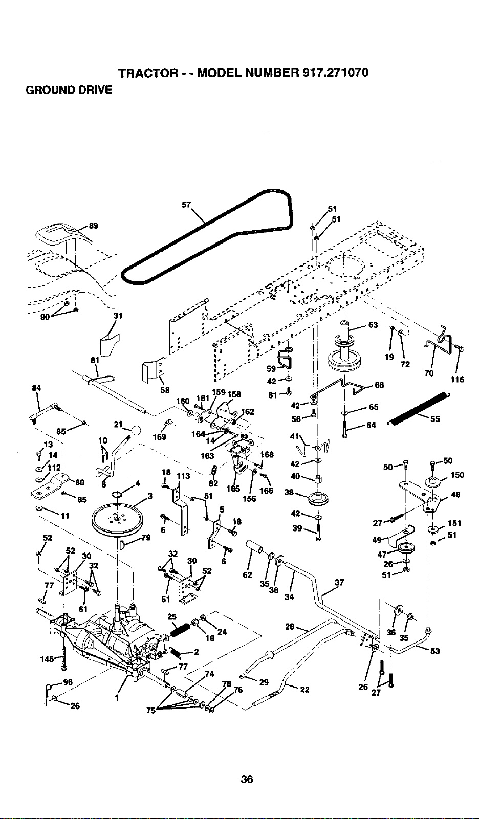
TRACTOR - oMODEL NUMBER 917.271070
GROUND DRIVE
75
26
27
36
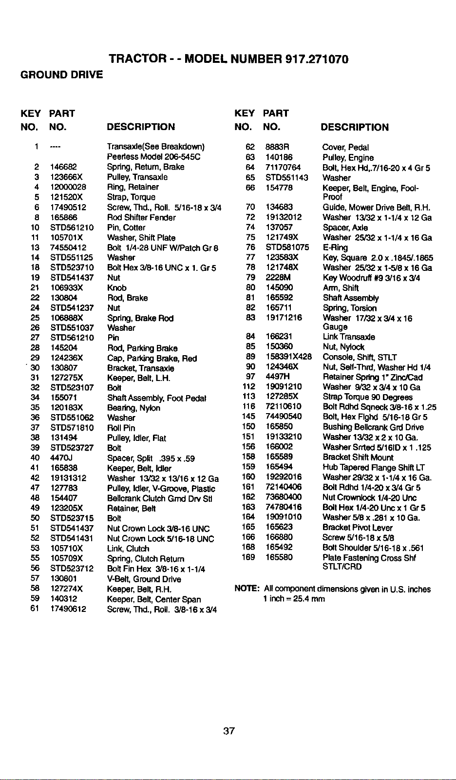
TRACTOR - - MODEL NUMBER 917.271070
GROUND DRIVE
KEY PART KEY PART
NO. NO. DESCRIPTION NO. NO. DESCRIPTION
1 .... Transaxle(See Breakdown) 62 8883R
PeerlessModel 206-545C 63 140186
2 146682 Spring,Retum, Brake 64 71170764
3 123666X Pulley,Transaxle 65 STD551143
4 12000028 Ring,Retainer 66 154778
5 121520X Strap,Torque
6 17490512 Screw,Thd., Roll. 5/16-18 x 3/4 70 134683
8 165866 RodShifter Fender 72 19132012
10 STD561210 Pin,Cotter 74 137057
11 105701X Washer,ShiftPlate 75 121749X
13 74550412 Bolt 1/4-28UNFW/PatchGr8 76 STD581075
14 STD551125 Washer 77 123583X
18 STD523710 Bolt Hex3i6-16UNCx 1.Gr5 78 121748X
19 STD541437 Nut 79 2228M
21 106933X Knob 80 145090
22 130804 Rod, Brake 81 165592
24 STD541237 Nut 82 165711
25 106888X Spring,Brake Rod 83 19171216
26 STD551037 Washer
27 STD561210 Pin 84 166231
28 145204 Rod, ParkingBrake 85 150360
29 124236X Cap, ParkingBrake, ROd 89 158391X428
• 30 130807 Bracket,Transaxle 90 124346X
31 127275X Keeper, Belt, L.H. 97 4497H
32 STD523107 Bolt 112 19091210
34 155071 ShaftAssembly,Foot Pedal 113 127285X
35 120183X Bearing,Nylon 116 72110610
36 STD551062 Washer 145 74490540
37 STD571810 Roll Pin 150 165850
38 131494 Pulley,Idler,Flat 151 19133210
39 STD523727 Bolt 156 166002
40 4470J Spacer,Split ,395 x .59 158 165589
41 165838 Keeper, Bolt, Idler 159 165494
42 19131312 Washer 13i32x13/16x12Ga 160 19292016
47 127783 Pulley,Idler,V-Groove, Plastic 161 72140406
48 154407 BellcrankClutchGrad Dn/Sit 162 73680400
49 123205X Retainer,Belt 163 74780416
50 STD523715 Bolt 164 19091010
51 STD541437 Nut CrownLock3/8-16 UNC 165 165623
52 STD541431 Nut CrownLock5/16-18 UNC 166 166880
53 105710X Link,Clutch 168 165492
55 105709X Spring,ClutchRetum 169 165580
56 STD523712 Bolt Fin Hex 3/8-16 x 1-1/4
57 130801 V-Bolt,Ground Drive
58 127274X Keeper, Belt,R.H. NOTE:
59 140312 Keeper, Belt,CenterSpan
61 17490612 Screw,Thd., ROll. 3/6-16 x 3/4
Cover,Pedal
Pulley,Engine
Bolt,Hex Hd,.7/16-20 x 4 Gr 5
Washer
Keeper, Belt, Engine,Fool-
Proof
Guide, MowerDrive Belt, R.H.
Washer 13/32 x 1-1/4 x 12 Ga
Spacer,Axle
Washer 25/32 x 1-1/4 x 16 Ga
E-Ring
Key, Square 2.0x .1845/.1865
Washer 25/32 x 1-5/8 x 16 Ga
Key Woodruff#9 3/16 x3/4
Arm, Shift
ShaftAssembly
Spring,Torsion
Washer 17/32 x 3/4 x 16
Gauge
LinkTransaxla
Nut, Nylock
Console,Shift, STLT
Nut, Seff-Thrd,Washer Hd 1/4
Retainer Spring 1"ZincJCed
Washer 9/32 x3/4 x 10Ga
StrapTorque90 Degrees
BoltRdhdSqneck 3/8-16 x 1.25
Bolt,Hex Rghd 5/16-18 Gr 5
BushingBellcrankGrd Drive
Weaher 13/32 x 2 x 10Ga.
Washer Srrted5/161Dx 1.125
Bracket ShiftMount
HubTapered Range ShiftLT
Washer 29/32 x 1-1/4 x 16 Ga.
BoltRdhd1/4-20 x3/4 Gr 5
Nut Crownlock1/4-20 Uric
BoltHex 114-20Unc x 1 Gr 5
Washer 5/8 x .281 x 10 Ga.
Bracket PivotLever
Screw5/16-18 x 5/8
BoltShoulder5/16-18 x .561
Plate FasteningCrossShf
STLT/CRD
AllcomponentdimensionsgiveninU.S. inches
1 inch= 25.4 mm
37
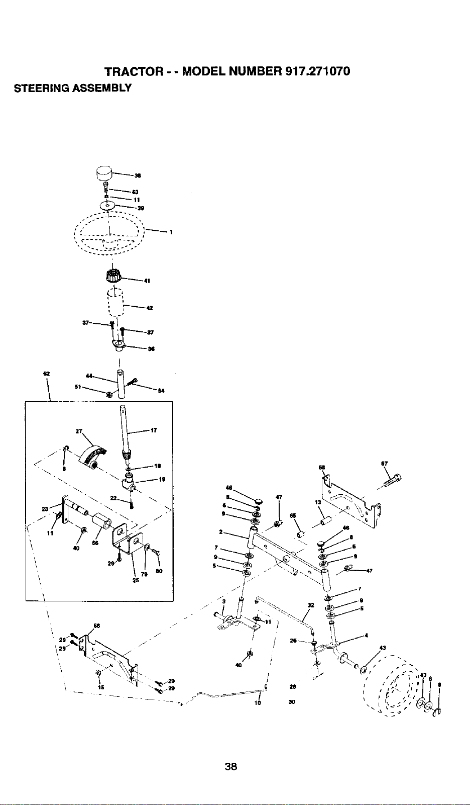
TRACTOR - - MODEL NUMBER 917.271070
STEERING ASSEMBLY
j ....... [. _j _ 1
I
117
2S
67
47
13
38
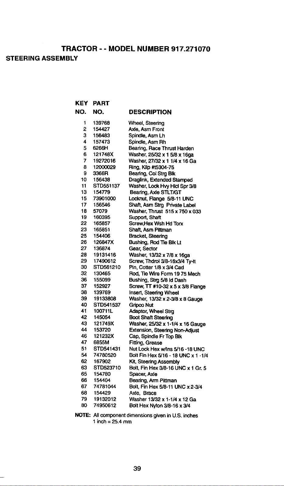
TRACTOR - - MODEL NU MBER 917.271070
STEERING ASSEMBLY
KEY PART
NO. NO. DESCRIPTION
t 139768
2 154427
3 156483
4 157473
5 6266H
6 121748X
7 19272016
8 12000029
9 3366R
10 156438
11 STD551137
13 154779
15 73901000
17 156546
18 57079
19 160395
22 165857
23 165851
25 154406
26 126847X
27 136874
28 19131416
29 17490612
30 STD561210
32 130465
36 155099
37 152927
38 139769
39 19133808
40 STD541537
41 100711L
42 145054
43 121749X
44 153720
46 121232X
47 6855M
51 STD541431
54 74780520
62 167902
63 STD523710
65 154780
66 154404
67 74781044
68 154429
79 19132012
80 74950612
NOTE:
Wheel, Steering
Axle,Asm Front
Spindle,AsmLh
Spindle,AsmRh
Beadng,Race ThrustHarden
Washer,25/32 x 1 5/8 x 16ga
Washer,27/32 x 1 1/4 x 16 Ga
Ring, Klip#t5304-75
Beadng,Col StrgBIk
Draglink,ExtendedStamped
Washer,LockHvy HlclSpr 3/8
Bearing,Axle STLT/GT
Locknut,Range 5/8-11 UNC
Shaft,Asm Strg PrivateLabel
Washer,Thrust 515 x 750 x 0.33
Support,Shaft
Screw,Hex Wsh HdTorx
Shaft,Asm Pittman
Bracket,Steering
Bushing,RodRe BIkLt
Gear, Sector
Washer, 13/32 x7/8x 16ga
Screw,Thdrot3/8-16x3/4 Ty-tt
Pin,Cotter 1/8 x3/4 Cad
Rod,-fie Wire Form 19 75 Mech
Bushing,Strg5/8 Id Dash
Screw,1-1"#10-32 x5 x 3/8 Flange
Insert,SteeringWheel
Washer, 13/32 x 2-3/8 x 8 Gauge
GdpcoNut
Adaptor,Wheel Strg
BootShaft Steering
Washer,25/32 x 1-1/4 x 16Gauge
Extension, SteeringNon-Adjust
Cap, Spindle FrTopBIk
Fitting,Grease
Nut LockHex w/Ins5/16 -18 UNC
BoltFinHex 5/16 - 18 UNC x I -1/4
Kit,SteeringAssembly
Bolt, FinHex 3/8-16 UNC x I Gr.5
Spacer,Axle
Bearing,Arm Pittman
Bolt, FinHex 5/8-11 UNC x 2-3/4
Axle, Brace
Washer 13/32 x 1-1/4 x 12 Ga
Bolt Hex Nylon3/8-16 x 3/4
Allcomponentdimensionsgivenin U.S. inches
1 inch= 25.4 mm
39
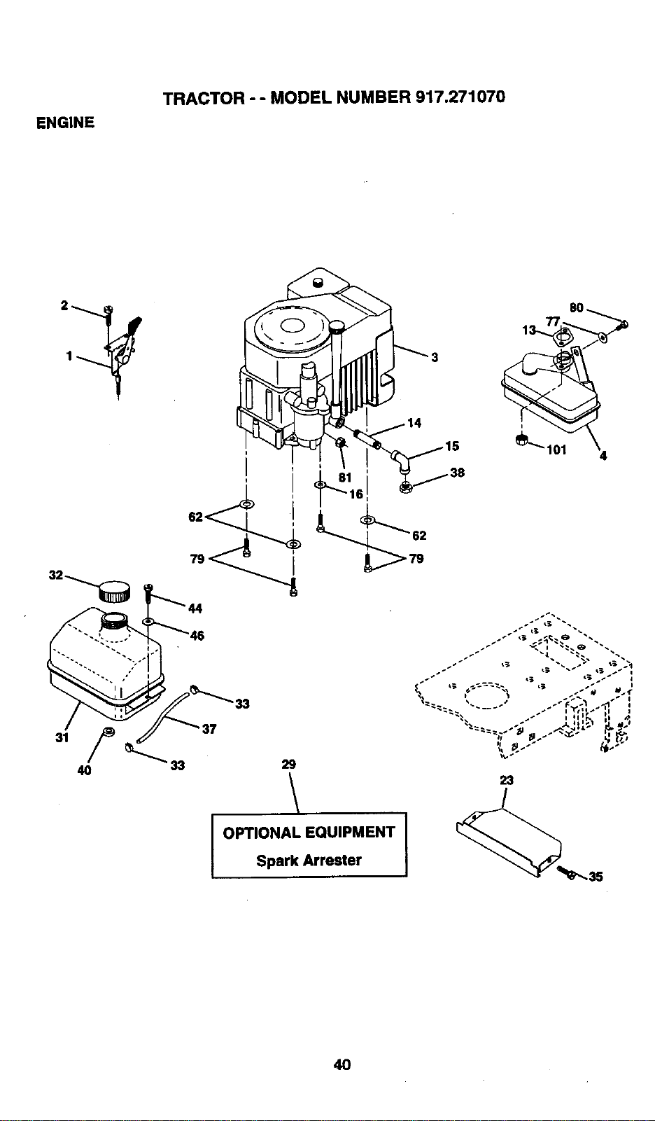
ENGINE
TRACTOR - - MODEL NUMBER 917.271070
6
33
29
OPTIONAL EQUIPMENT I
Spark Arrester
23
/
4O
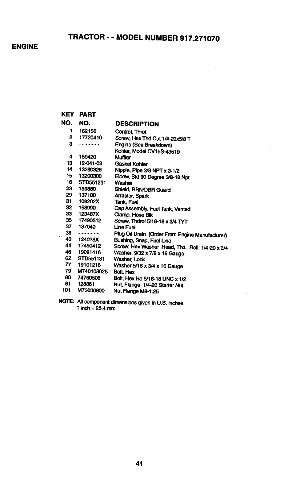
ENGINE
TRACTOR - - MODEL NUMBER 917.271070
KEY PART
NO. NO.
1 162156
2 17720410
3 .......
4 15942O
13 12041-03
14 1328O328
15 13200300
16 STD551231
23 159880
29 137180
31 109202X
32 158990
33 123487X
35 17490512
37 137040
38 .......
40 124028X
44 17490412
46 19091416
62 STD551131
77 19101216
79 M740108025
80 74760508
81 128861
101 M730308(X)
DESCRIPTION
Control,Throt
Screw,HexTnd Cut 1/4-20x5/8 T
Engine(See Breakdown)
Kohler'Modet CV16S-43,519
Mutter
GasketKohler
Nipple,Pipe 3/8 NPT x 3-1/2
Elbow,Std90 Degree 3/8-18 Npt
Washer
Shield, BRN/DBR Guard
Arrestor,Spark
Tank, Fuel
Cap Assembly,Fuel Tank,Vented
Clamp,Hose BJk
Screw,Thdrol5/16-18 x 3/4 "rY'I"
LineFuel
PlugOil Drain (Order FromEngineManufaetumr)
Buel_ug,Snap, Fuel Line
Screw,HexWasher Head, Thd. Roll. 1/4-20 x 3/4
Washer,9/32 x 7/8 x 16Gauge
Washer, Lock
Washer 5/16 x 3/4 x 16 Gauge
Bolt, Hex
Bolt,Hex Hd5/16-18 UNC x 1/2
Nut,Range 114-20StarterNut
Nut Range M6-1.2.5
NOTE: All componentdimensionsgiven inU.S. inches
1inch =25.4 mm
4t
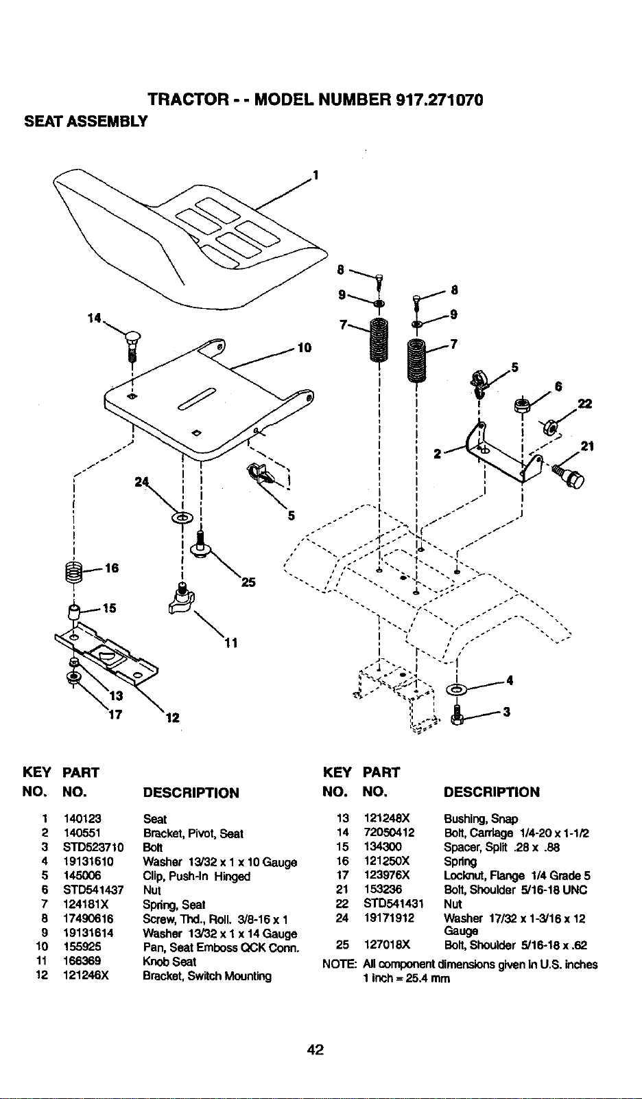
TRACTOR - - MODEL NUMBER 917.271070
SEAT ASSEMBLY
KEY PART KEY PART
NO, NO. DESCRIPTION NO. NO. DESCRIPTION
1 140123 Seat 13 121248X Bushing,Snap
2 140551 Bracket,Pivot, Seat 14 72050412 Bolt,Carriage 1/4-20 x 1-1/2
3 STD523710 Bolt 15 134300 Spacer,Split .28 x .88
4 19131610 Washer 13/32 x 1x 10Gauge 16 121250X Spring
5 145006 Clip, Push-In Hinged 17 123976X Locknut,Flange 1/4 Grade5
6 STD541437 Nut 21 153236 Bolt,Shoulder 5/16-19 UNC
7 124181X Spdng,Seat 22 STD541431 Nut
3 17490616 Screw,Thd., Roll. 3/8-16 x I 24 19171912 Washer 17/32 x 1-3/16 x 12
9 19131614 Washer 13/32 x I x 14 Gauge Gauge
10 155925 Pan, Seat EmbossQCK Conn. 25 127018X Bolt, Shoulder 5/16-18 x .62
11 166369 KnobSeat NOTE: All oomponentdimensionsgiveninU.S. inches
12 121246X Bracket,SwitchMounting 1 inch= 25.4 mm
42
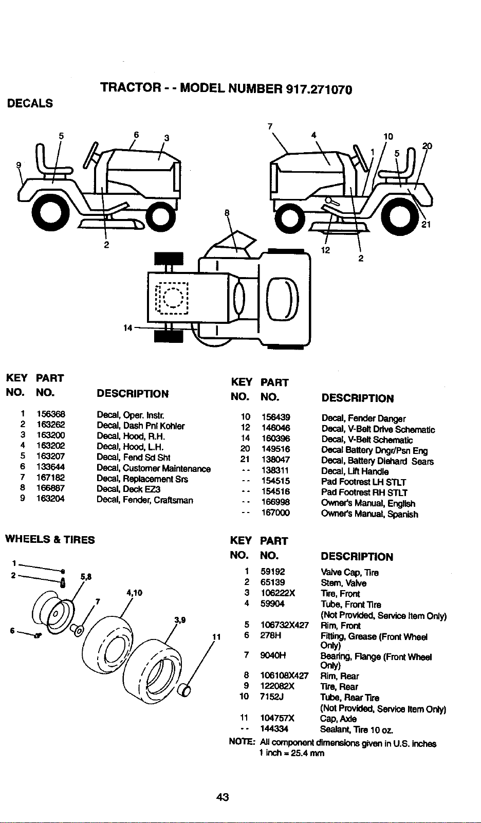
DECALS
TRACTOR - - MODEL NUMBER 917.271070
6 3
4
12
10
KEY PART
NO. NO.
1 156368
2 163262
3 16320O
4 1632(_
5 163207
6 133644
7 167182
8 166887
9 163204
KEY PART
DESCRIPTION NO. NO.
Decal, Oper. Instr. 10 156439
Decal, Dash Pnl Kohler 12 146046
Decal, Hood, R.H. 14 160396
Decal, Hood, LH. 20 149516
Decal, Fend Sd Sht 21 138047
DecaJ,Customer Maintenance - - 138311
Decal,ReplacementSm - - 154515
Decal,Deck EZ3 - - 154516
Decal, Fender,Craitsman - - 166998
- - 167000
DESCRIPTION
Decal, Fender Danger
Decal, V-BeltDrive Schematic
Decal, V-BeltSchematic
Decal Battery Ongr/PsnF_ng
Decal, Battery Diehard Sears
Decal,LiftHandle
Pad FootrestLH STLT
Pad FootrestRH STLT
Owners Manual, English
Owners Manual, Spanish
WHEELS & TIRES
4,10
11
KEY PART
NO. NO. DESCRIPTION
1
2
3
4
8
9
lO
11
°.
59192 ValveCap, Tire
65139 Stem, Valve
106222X Tire, Front
59904 Tube, FrontTire
(NotPmvtded, ServiceitemOnly)
106732X427 Rim, Front
2781-1 Frffing,Grease (FrontWheel
Only)
9040H Beadng,Flange (FrontWheel
ore/)
106108)(427 Rim, Rear
122082X Tire, Rear
7152J Tube, Rear Tire
(Not Provided,ServiceItem Only)
104757X Cap,Axle
144334 Sealant,Ttre 10 oz.
NOTE: Allcomponentdimensionsgivenin U.S. inche6
1 inch= 25.4 mm
43
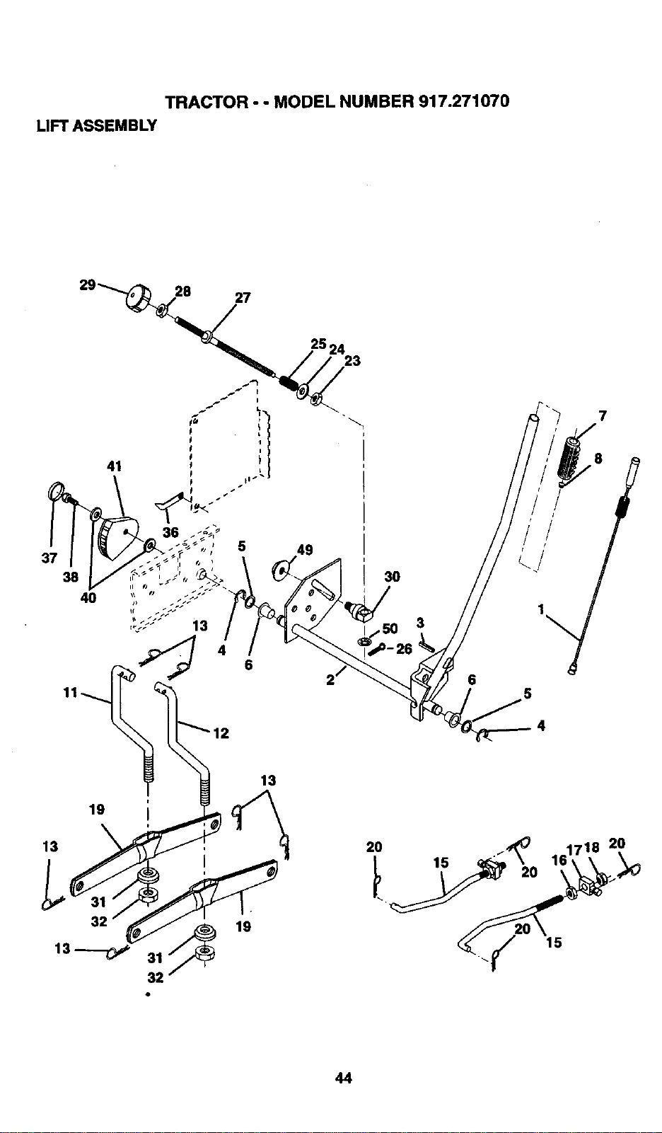
TRACTOR - - MODEL NUMBER 917.271070
LIFTASSEMBLY
28 27
38
4O
41
36
5
13
6
23
3O
3
7
19
13
31 _ 19
32'
13
20 i'_ 1718 20
_ _/" 15
44
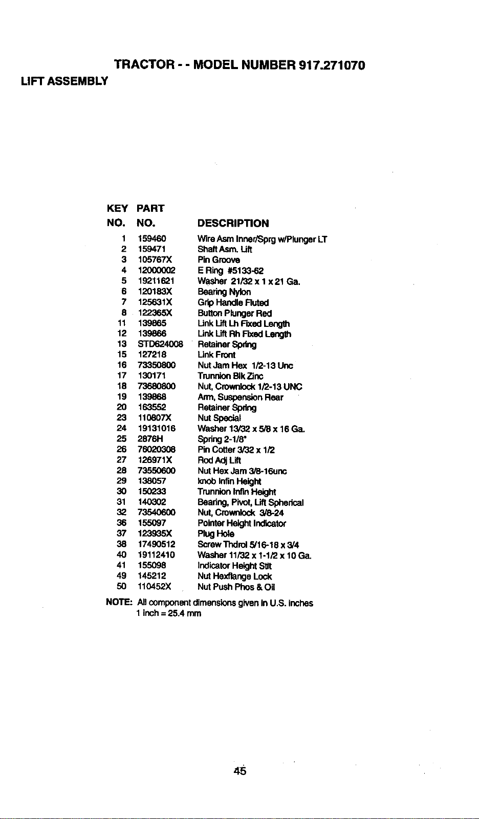
TRACTOR - - MODEL NUMBER 917.271070
LIFT ASSEMBLY
KEY PART
NO. NO. DESCRIPTION
1 159460 Wire Asm Inner/Sprgw/Plunger LT
2 159471 ShaftAsm. Lift
3 105767X PinGRove
4 120000(_ ERing #5133-62
5 19211621 Washer 21/32 xI x21 Ga.
6 120183X BearingNylon
7 125631X GripHandle Ruted
8 122365X ButtonPlungerRed
11 139865 Unk LiftLh Fixed Leng_t
12 139866 Unk Uft RhF'lxedLength
13 STD624008 RetainerSpring
15 127218 Unk Front
16 73350800 NutJamHex 1/2-13Unc
17 130171 TnJnnionBIkTinc
18 73680800 Nut, Crownlock1/2-13 UNC
19 139868 Arm, SuspensionRear
20 163552 RetainerSpdng
23 11(_607X Nut Special
24 19131016 Washer 13/32 x 5/8 x 16 Ga.
25 2876H Spring2-1/8"
26 760_ PinCotter3/32 x 1/2
27 126971X RodAdjLift
28 73550600 Nut Hex Jam 3/8-16unc
29 138057 knobInfinHeight
30 15(7233 TrunnionIntinHeight
31 140302 Beadng, Pivot,LiftSpherical
32 73540600 Nut, Crownlock 3/8-24
36 155097 PointerHeight Indicator
37 123935X Plug Hole
38 17490512 ScrewThdrol 5/'16-18x 3/4
40 19112410 Washer 11/32x 1-1/2 x 10 Ga.
41 155098 IndicatorHeightStlt
49 145212 Nut Hexflange Lock
50 110452X Nut PushPhos& Oil
NOTE:
All componentdimensionsgiven inU.S. inches
1 inch= 25.4 mm
5
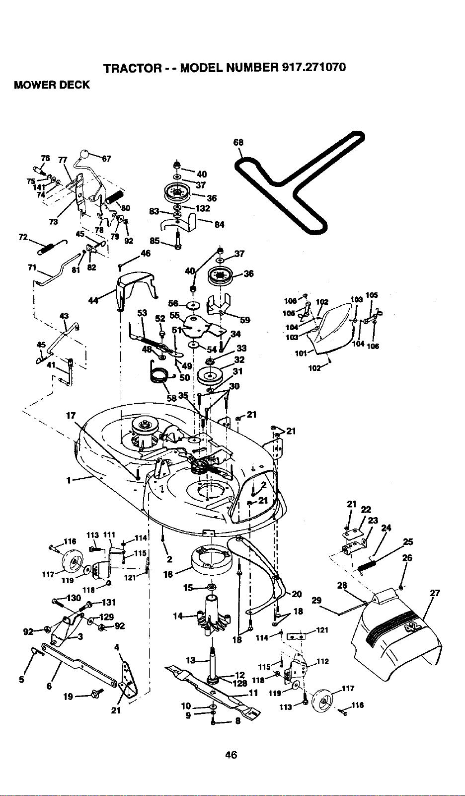
TRACTOR - - MODEL NUMBER 917.271070
MOWER DECK
68
31 1°2"_"
\
2
16
18
21
22
/23
24
29
26
27
46
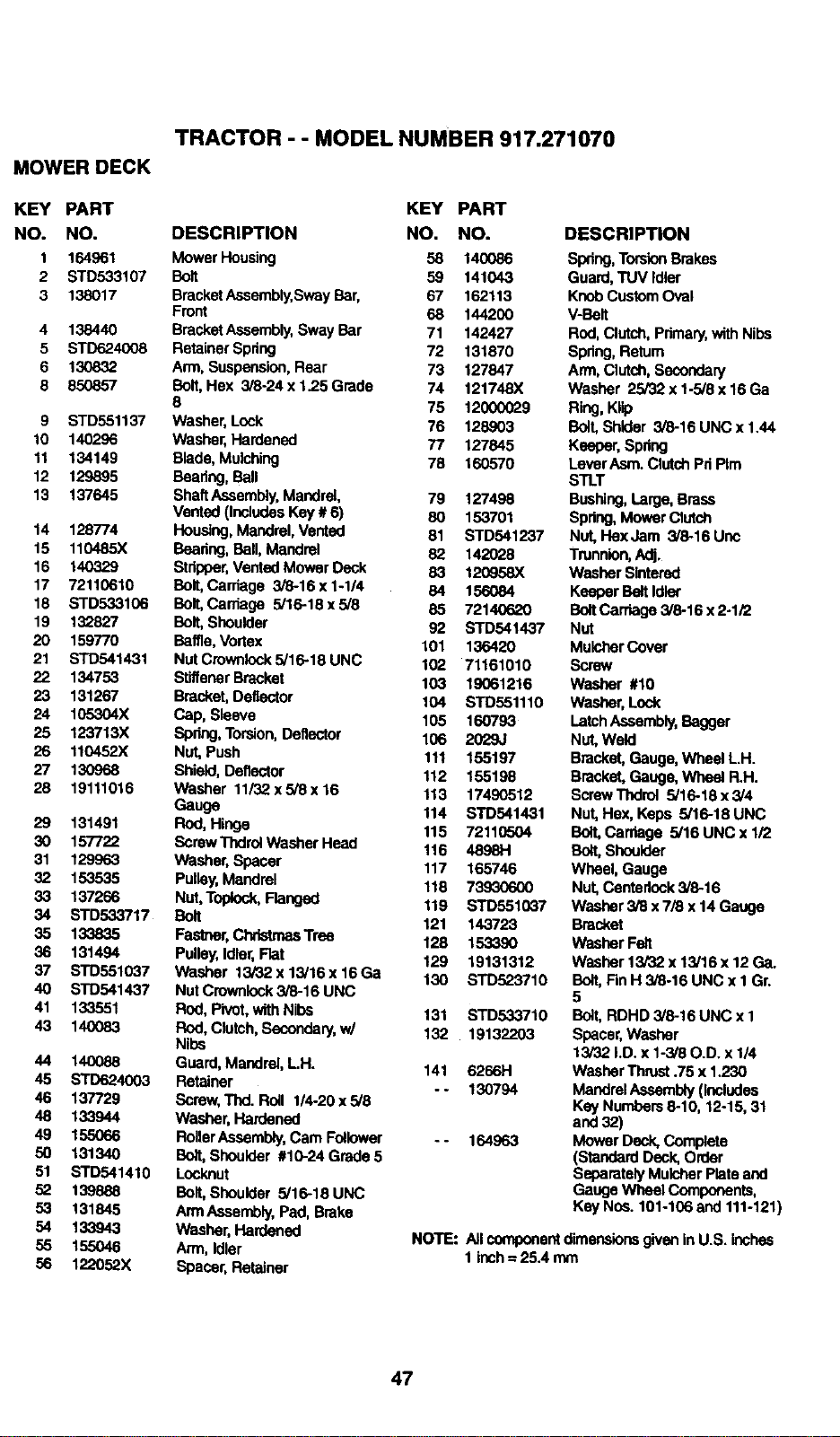
MOWERDECK
TRACTOR - - MODEL NUMBER 917.271070
KEY PART KEY PART
NO. NO. DESCRIPTION NO. NO.
1 164961 Mower Housing 58 140086
2 STD533107 Bolt 59 141043
3 138017 BracketAssembly,SwayBar, 67 162113
Front 68 144200
4 138440 BracketAssembly,Sway Bar 71 142427
5 STD624008 RetainerSpdng 72 131870
6 130832 Arm, Suspension,Rear 73 127847
8 850857 Bolt,Hex 3/6-24 x 1.25 Grade 74 121748X
8 75 12000029
9 STD551137 Washer,Lock 76 128903
10 140296 Washer,Hardened 77 127845
11 134149 Blade, Mulching 78 160570
12 129895 Beadng, Ball
13 137645 ShaftAssembly,Mandrel, 79 127498
Vented(IncludesKey # 6) 80 153701
14 128774 Houaing, Mandrel,Vented 81 STD541237
15 110485X Bearing,Ball, Mandrel 82 142028
16 140329 Stripper,Vented Mower Deck 83 120958X
17 72110610 Bolt,Carriage 3/8-16 x 1-1/4 84 156084
18 STD533106 Bolt, Cardage 5/16-18 x 5/8 85 72140620
19 132827 Bolt,Shoulder 92 STD541437
20 159770 Baffle, Vortex 101 136420
21 STD541431 NutCrownlock5/16-18UNC 102 71161010
22 134753 SltffenerBracket 103 19061216
23 131267 Bracket,Deflector 104 STD551110
24 105304X Cap, Sleeve 105 160793
25 123713X Spdng,Torsion,Deflector 106 2029J
26 110452X Nut,Push 111 155197
27 130968 Shield, Deflector 112 155198
28 19111016 Washer 11/32 x 5/8 x16 113 17490512
Gauge 114 STD,5414,31
29 131491 Rod, Hinge 115 72110504
30 157722 ScrewThdrolWasherHead 116 4898H
31 129963 Washer,Spacer 117 165746
32 153535 Pulley,Mandrel 118 73930600
33 137266 Nut, Toplock,Flanged 119 STD551037
34 STD533717 Bolt 121 143723
35 133835 Fastner,ChdetmasTree 128 1533,90
36 131494 Pulley,Idler,Flat 129 19131312
37 STD551037 Washer 13/32 x 13/16 x 16 Ga 130 STD523710
40 STD541437 Nut Crownlock3/8-16 UNC
41 133551 Rod, Pivot,with Nib6 131 STD533710
43 140083 Rod, Cletch,Secondary,w/ 132 19132203
Nibs
44 140088 Guard, Mandrel, LH. 141 6266H
45 STD624003 Retainer
- - 130794
46 137729 Borew, Thd. Roll 114-20x5/8
48 133944 Washer, Hardened
49 155066 RollerAssembly,Cam Follower - - 164963
50 131340 Bolt,Shoulder #10-24 Grade 5
51 STD541410 Locknut
52 139888 Bolt, Shoulder 5/16-18 UNC
53 131845 ArmAssernbly,Pad, Brake
54 133943 Washer, Hardened
55 155046 Arm, Idler
56 122052X Spacer, Retainer
DESCRIPTION
Swing, TorsionBrakes
Guard, TUV Idler
KnobCustomOval
V-Bolt
Rod,Clutch, Pdmary,with Nibs
Swing, Relurn
Arm, Clutch, Secondary
Washer 25/32 x 1-5/8 x 16Ga
Ring,Klip
Bolt,Shlder 3/8-16 UNC x 1.44
Keeper, Spdng
LeverAsm. ClutchPriPIm
STLT
Bushing,Large,Brass
Swing, Mower Clutch
Nut, HexJam 3/6-16 Unc
Trunnion,Adj.
Washer Sintered
Keeper BeltIdler
BoltCarriage3/6-16 x 2-1/2
Nut
MulcherCover
Screw
Washer #10
Washer, Lock
Latch Assembly,Bagger
Nut,Weld
Bracket,Gauge, Wheel L.H.
Bracket,Gauge, Wheel R.H.
ScrewThdrol 5/16-18 x 3/4
Nut,Hex, Keps 5/16-18 UNC
Bolt,Carriage 5/16 UNC x 1/2
Bolt,Shoulder
Wheel, Gauge
Nut, Centerlock3/6-16
Washer 3/8 x7/8 x 14 Gauge
Bracket
Washer Fen
Washor 13/32 x 13/18 x 12 Ga.
BOlt,FinH 3/8-16 UNC x I Gr.
5
Bolt,RDHD 3/6-18 UNC x I
Spacer,Washer
13/32 hD. x I-3/8 O.D. x 114
Washer Thrust.75 x 1.230
MandrelAssembly(Includes
Key Numbers6-10, 12o15,31
and 32)
Mower Deck, Complete
(Standard Deck, Order
SeparatelyMulcherPlate and
Gauge Wheel Components,
Key Nns. 101-106 and 111-121)
NOTE: All componentdimensionsgivenin U.S. inches
1 inch-- 25.4 mm
47
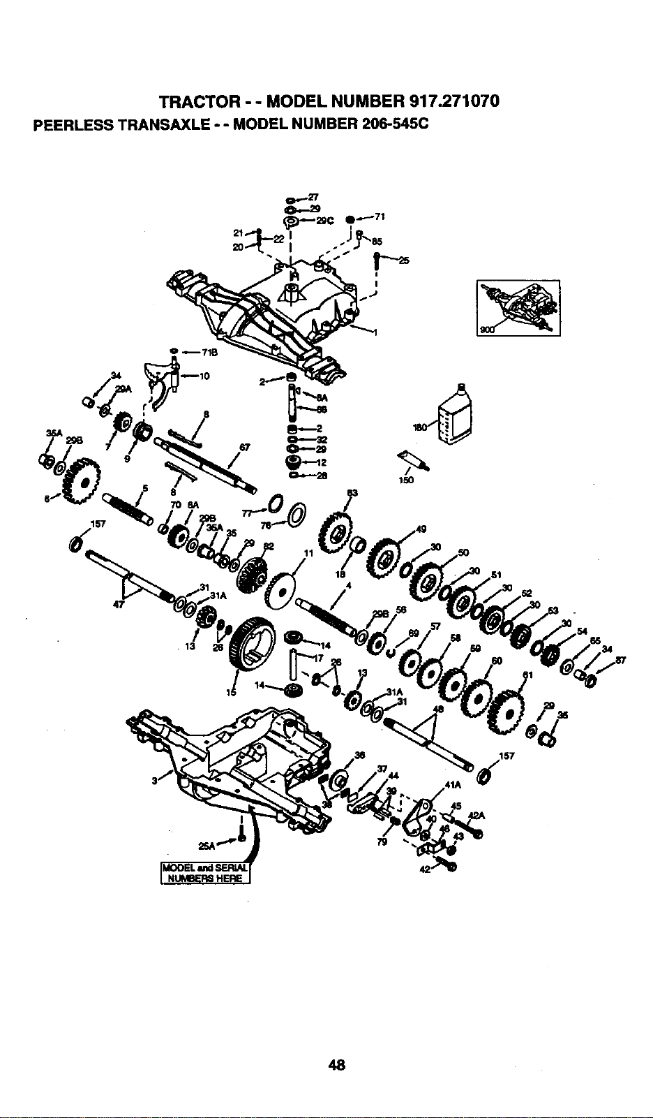
TRACTOR - - MODEL NUMBER 917.271070
PEERLESS TRANSAXLE - - MODEL NUMBER 206-545C
157
47
8
8
708A
13
11
150
2g
35
48
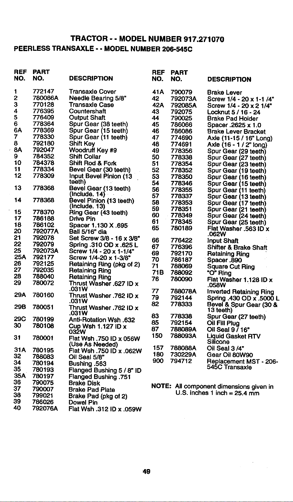
TRACTOR - - MODEL NUMBER 917.271070
PEERLESSTRANSAXLE-- MODELNUMBER206-545C
REF PART REF PART
NO. NO. DESCRIPTION NO. NO.
1 772147 Transaxle Cover 41A 790079
2 780086A Needle Beadng 518" 42 792073A
3 770128 Transaxle Case 42A 792085A
4 776395 Countershaft 43 792075
5 776409 Output Shaft 44 790025
6 778364 Spur Gear (38 teeth) 45 786066
6A 778369 Spur Gear (15 teeth) 46 786086
7 778330 Spur Gear (11 teeth) 47 774690
8 792180 Shift Key 48 774691
, 8A 792047 Woodruff Key #9 49 778356
9 784352 Shift Collar 50 778338
10 784378 Shift Rod & Fork 51 778354
11 778334 Bevel Gear (30 teeth) 52 778352
12 778309 Input Bevel Pinion (13 53 778350
teeth) 54 778346
13 778368 Bevel Gear (13 teeth) 56 778355
(Include. 14) 57 778337
14 778368 Bevel Pinion (13 teeth) 58 778353
(Include. 13) 59 778351
• 15 778370 Ring Gear (43 teeth) 60 778349
17 786188 Ddve Pin 61 778345
18 786102 Spacer 1.130 X .695 65 780189
20 792077A Ball 5/16" dia
21 792078 Sat Screw 3/8 - 16 x 3/8" 66 776422
22 792079 Spdng ,310 OD x .625 L 67 776396
25 792073A Screw 1/4 - 20 x 1-1/4" 69 792170
25A 792177 Screw 1/4-20 x 1-3/8" 70 786187
26 792125 Retaining Ring (pkg of 2) 71 788069
27 792035 Retaining Ring 71B 788092
28 788040 Retaining Ring 76 780090
29 780072 Thrust Washer .627 ID x
,031W 77 788078A
29A 780160 Thrust Washer .762 ID x 79 792144
.031W 82 778333
29B 780051 Thrust Washer .762 ID x
,031W 83 778338
29C 780199 Anti-Rotation Wsh .632 85 792154
30 780108 Cup Wsh 1.127 ID x 87 788089A
032W
31 780001 Flat Wsh .750 ID x 056W 150 788093A
(Use As Needed) 157 788088A
31A 780195 FlatWsh .750 ID x .062W
32 788083 Oil Seal 5/8" 180 730229A
34 780194 Bushing ,563 900 794712
35 780193 Flanged Bushing 5 / 8" ID
35A 780197 Flanged Bushing .751
36 790075 Brake Disk
37 790007 Brake Pad Plate
38 799021 Brake Pad (pkg of 2)
39 786026 Dowel Pin
40 792076A Flat Wsh .312 ID x ,059W
DESCRIPTION
Brake Lever
Screw 1/4 - 20 x 1-1/4"
Screw 1/4 - 20 x 2 1/4"
Locknut 5 / 16 - 24
Brake Pad Holder
Spacer .2625 x 1.0
Brake Lever Bracket
Axle (11-15 / 16" Long)
Axle (16 - 1 / 2" long)
Spur Gear (29 teeth)
Spur Gear (27 teeth)
Spur Gear (23 teeth)
Spur Gear (19 teeth)
Spur Gear (16 teeth)
Spur Gear (15 teeth)
Spur Gear (11 teeth)
Spur Gear (13 teeth)
Spur Gear (17 teeth)
Spur Gear (21 teeth)
Spur Gear (24 teeth)
Spur Gear (25 teeth)
Flat Washer .563 ID x
.062W
Input Shaft
Shifter & Brake Shaft
Retaining Ring
Spacer .890
Square Cut Ring
"O" Ring
Flat Washer 1.128 ID x
.058W
Inverted Retaining Ring
Spdng .430 OD x .5000 L
Bevel & Spur Gear (30 &
13 teeth)
Spur Gear (27 teeth)
Oil Fill Plug
Oil Seal 9 / 16"
Li..quidGasket RTV
IIIcone
Oil Seal 314"
Gear Oil 80W90
Replacement MST - 206-
545(3 Transaxle
NOTE: All component dimensions given in
U.S. inches I inch = 25.4 mm
49
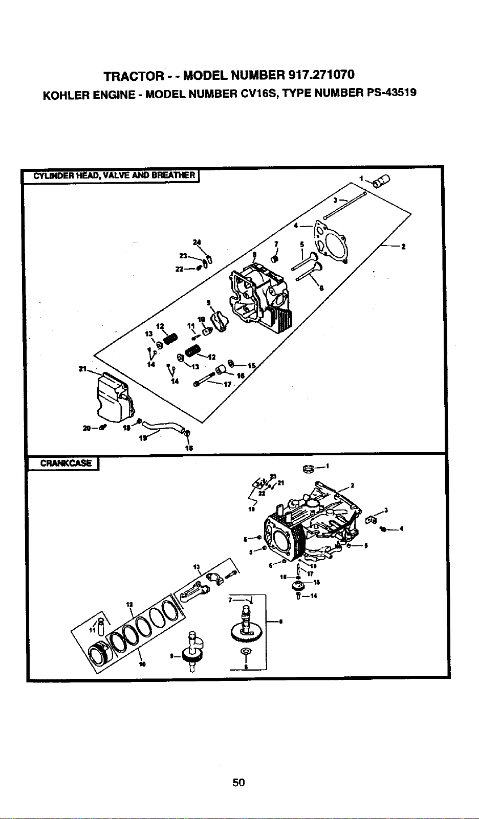
TRACTOR - - MODEL NUMBER 917.271070
KOHLER ENGINE - MODEL NUMBER CV16S, TYPE NUMBER PS-43519
CYUNDER HEAD, VALVE AND BREATHER
C_t_KCk_ I
lS
1|
5O
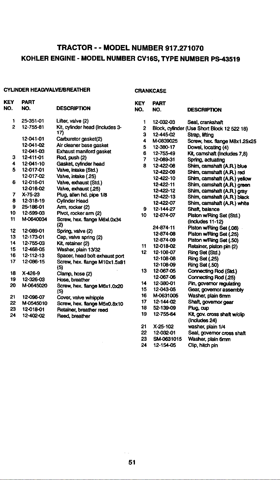
TRACTOR - - MODEL NUMBER 917.271070
KOHLER ENGINE - MODEL NUMBER CV16S, TYPE NUMBER PS-43519
CYLINDER HEAD/VAlVE/BREATHER
KEY PART
NO. NO.
CRANKCASE
3
4
5
7
8
9
10
11
12
13
14
15
16
17
18
19
2O
21
22
23
24
25-351-01
12-755-81
12-041-01
12-041-02
12-041-03
12-411-01
12-041-10
12-017-01
12-017-0_
12-016-01
12-016-(_
X-75-23
12-318-19
25-186-01
12-599-03
M-0640034
12-089-01
12-173-01
12-755-03
12-468-05
12-112-13
12-086-15
X-425-9
12-326-03
M-0645020
12-096-07
M-0545010
12-018-01
12-4(_-(_
KEY PART
DESCRIPTION NO. NO.
Lifter,valve (2)
Kit,cylinderhead(Includes3-
17)
Carburetorgasket(2)
Aircleaner basegasket
Exhaustmanifordgasket
Rod,push (2)
Gasket,cytinderhead
Valve, intake(Std.)
Valve, intake(.25)
Valve,exhaust(St=t)
Va_, exhaust(.2s)
Plug,allenhd. pipe118
CylinderHead
Arm, rocker(2)
Pivot,rockerann (2)
Screw,hex.flange M6xl.0x34
(2)
Spring,valve (2)
Cap, valve spring(2)
Kit,retainer(2)
Washer,plain13/32
Spacer,head boltexhaustport
Screw,hex. flangeM10x1,5x81
(5)
Clamp,hose (2)
Hose, breather
Screw, hex. flangeM6xl.0x20
(5)
Cover,valve w/nipple
Screw, hex. flangeM5_O.Sx10
Retainer,breatherreed
Reed, breather
DESCRIPTION
1
2
3
4
5
6
7
8
9
10
11
12
t3
14
15
16
17
18
19
21
22
23
24
12-032-03 Seal, crankshaft
Block,cylinder(Use ShortBlock12 522 18)
12-445-02
M-0839025
12-380-17
12-755-49
12-089-31
12-422-08
12-422-09
12-422-10
12-422-11
12-422-12
12-422-13
12-422-07
12-144-27
12-874-07
24-874-11
12-874-08
12-874-09
12-O18-02
12-108-07
12-108-08
12-108-O9
12-067-05
12-067-06
12-380-O1
12-043-05
M-0631005
12-144-(_
52-139-09
12-755-64
X-25-102
12-032-01
SM-0631015
12-154-05
Strap, lifting
Screw,hex. flangeM8x1.25x25
Dowel, locating(4)
Kit,camshaft(Includes7,8)
Spring,actuating
Shim, camshaft(A.R.) blue
Shim, camshaft (A.R.) red
Shim, camshaft (A.R.) ye6ow
Shim, camshaft (A.R.) green
Shim, camshaft (A.R.) gray
Shim, camshaft(A.FL)black
Shim,camshaft(A.R.) white
Shaft,balance
Pistonw/Ring Set(Std.)
pndudea11-12)
Pistonw/Ring Set(.08)
Pistonw/Ring Set(.25)
Pistonw/RngSet(.5o)
Retainer,pistonpin(2)
RingSet (Std.)
RingSet (.25)
RingSet (.50)
connec_ngRod(Std.)
connectingRod(.2S)
Pin,governorregulating
Gear,governorassembly
Washer, plain6mm
Shall governorgear
Plug,cup
Kft,gOV.cross shaftw/cltp
(Includes24)
washer,plain1/4
Seal,gavemor cross shaft
Washer, plain6mm
Clip, hitchpin
51
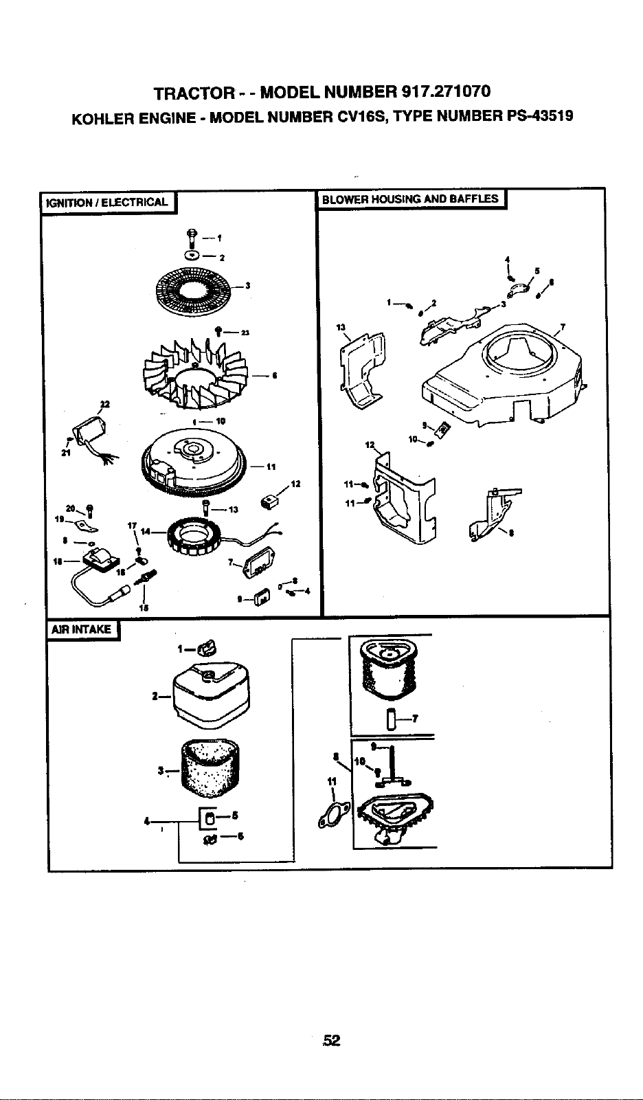
TRACTOR - - MODEL NUMBER 917.271070
KOHLER ENGINE - MODEL NUMBER CV16S, TYPE NUMBER PS-43519
IGNITION / ELECTRICAL I
_h23
,,-_,._ .-_ _.
,-8
BLOWER HOUSING AND BAFFLES I
13
4
! 5
i
'1'1 i
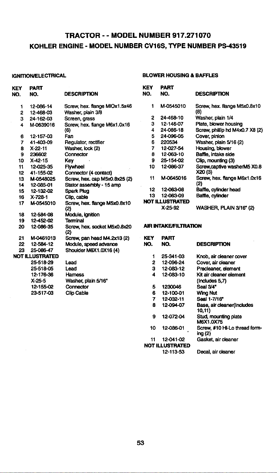
TRACTOR - - MODEL NUMBER 917.271070
KOHLER ENGINE - MODEL NUMBER CV16S, TYPE NUMBER PS-43519
IGNmON/ELECTRICAL
KEY PART
NO. NO.
BLOWER HOUSING & BAFFLES
1 12-086-14
2 12-468-03
3 24-162-03
4 M-0639016
6 12-157-03
7 41-403-09
8 X-22-11
9 236602
10 X-42-15
11 12-025-35
12 41-155-02
13 M-0548025
14 12-085-01
15 12-132-02
16 X-725-1
17 M-0545010
18 12-584-08
19 12-452-0_
20 12-086-35
21 M-0461013
22 12-584-12
23 25-086-47
NOT ILLUSTRATED
25-518-29
25-518-05
12-176-36
X-25-5
12-155-(_
23-517-03
KEY PART
DESCRIPTION NO. NO. DESCRIPTION
Screw,hex.flange MIOx1.5x46 1 M-0545010
Washer, plain3/8
Screen,grass 2 24-468-10
Screw,hex. flangeM6x1.0x16 3 12-146-07
(6) 4 24-086-18
Fan 5 24-096-05
Regulator,rectifier 6 220534
Washer, lock(2) 7 12-027-54
Connector 8 12-063-10
Key 9 25-154-02
Flywheel 10 12-086-37
Connector(4 contact)
Screw,heY-cap M5x0.8x25 (2) 11 M-0645016
Statorassembly- 15amp
Spark Plug 12 12-063-08
Clip,cable 13 12-063-09
Screw, hex. flangeM5x0.8xl0 NOT ILLUSTRATED
(2) X-25-92
Module, ignition
Temfinal
Screw,hex. socketM5x0.8x20 AIR INTAKE/FILTRATION
(2)
Screw, pan head M4.2x13 (2) KEY PART
Module, speed advance NO. NO.
ShoulderM6X1.0X16 (4)
Lend
Lend
Harness
Washer, plain5/16-
Connector
Clip Cable
Screw,hex. flangeM5x0.8xl0
(s)
Washer, plain1/4
Plate, blowerhousing
Screw, philliphdM4xO.7X8 (2)
Cover, pinion
Washer, plain5/16 (2)
Housing,blower
Baffle,intakeside
Clip, mounting(3)
Screw,captivewasherM5 X0.8
X20(3)
Screw,hex. flange M6x1.0x16
(2)
Baffle, cylinderhead
Baffle,cylinder
WASHER, PLAIN 3/16" (2)
DESCRIPTION
1 25-341-03
2 12-096-24
3 12-083-12
4 12-083-10
5 1230046
6 12-100-01
7 12-032-11
8 12-094-07
9 12-072-04
10 12-086-01
11 12-041-02
NOT ILLUSTRATED
12-113-53
Knob,aircleaner cover
Cover, air cleaner
Predenner,element
Kitair cleaner element
(Includas5,7)
Seal3/4"
Wing Nut
Seal 1-7/16"
Base, airclenner(Includes
10,11)
Stud,mountingplate
M6X1.0X75
Screw,#10 HI-Lothreadform-
ing(2)
Gasket,air cleaner
Decal,air cleaner
53
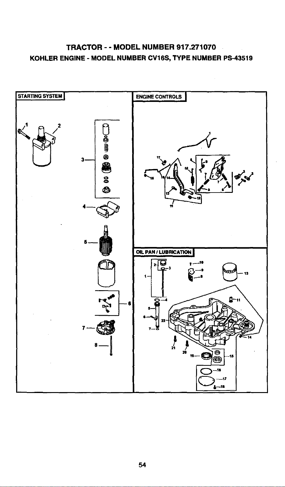
TRACTOR - - MODEL NUMBER 917.271070
KOHLER ENGINE - MODEL NUMBER CV16S, TYPE NUMBER PS-43519
STARTING SYSTEM I
i i
0
o
e,
3m O
,..I
!
8--
ql
ENGINECONTROLS I
,_,_ _-..
OIL pAN I LUBRiCATiON I
__, ,-': @
_ --13
I-- I
54
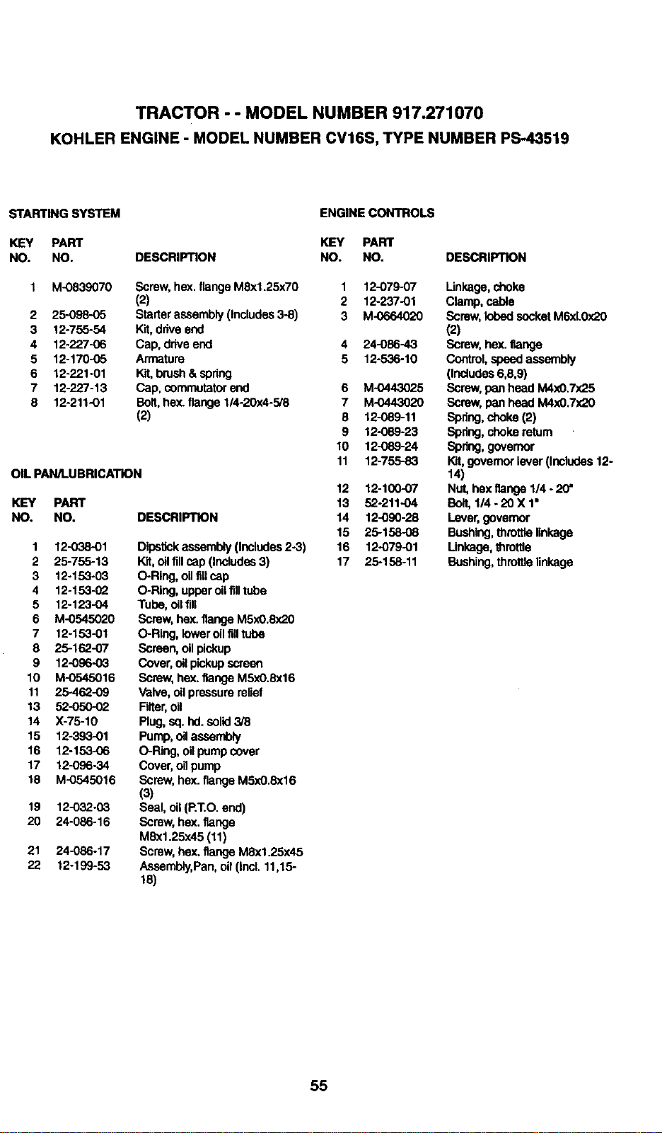
TRACTOR - - MODEL NUMBER 917.271070
KOHLER ENGINE - MODEL NUMBER CV16S, TYPE NUMBER PS-43519
STARTING SYSTEM ENGINE CONTROLS
KEY PART KEY PART
NO. NO. DESCRIPTION NO. NO. DESCRIPTION
1 M-0839070 Screw, hex.flangeM8x1.25xT0 1 12-079-07
(2) 2 12-237-01
2 25-098-05 Starterassembly(Includes3-8) 3 M-0664020
3 12-755-54 Kit,driveend
4 12-227-06 Cap, drive end 4 24-086-43
5 12-170-05 Armature 5 12-536-10
6 12-221-01 Kit,brush& spring
7 12-227-13 Cap, commutatorend 6 M-0443025
8 12-211-01 Bolt,hex. flange1/4-20x4-5/8 7 M-0443020
(2) 8 12089-11
9 12-089-23
10 12-089-24
11 12-755-83
OIL PAN/LUBRICATION
12 12-100-07
KEY PART 13 52-211.O4
NO. NO. DESCRIPTION 14 12-090-28
15 25-158-08
1 12-038-01 Dipstickassembly (Includes2-3) 16 12-079-01
2 25-755-13 Kit,oilfillcap (Includes3) 17 25-158-11
3 12-153-03 O-Ring, oilfillcap
4 12-153-02 O-Ring, upperoil filltube
5 12-123-O4 Tube,oil fill
6 M-0545020 Screw, hex. flangeM5x0.8x20
7 12-153-01 O-Ring, loweroilfilltube
8 25-162-07 Screen, oil pickup
9 12-096-03 Cover, oil pickupscreen
10 M-0545016 Screw, hex.flange MSx0.Sx16
11 25-462-09 Valve, oil pressurerelief
13 52-050-02 Filter,oil
14 X-75-10 Plug,sq.hd. solid3/8
15 12-393-01 Pump, oil assembly
16 12-153-06 O-Ring, oil pumpcover
17 12-096-34 Cover,oil pump
18 M-0545016 Screw, hex.flange M5x0.8x16
(3)
19 12-032-03 Seal, oil (RT.O. end)
20 24-086-16 Screw, hex.flange
MSx1.25x45 (11)
21 24-086-17 Screw,hex.flangeM8x1.25x45
22 12-199-53 Assembly,Pan, oil (Incl. 11,15-
18)
Linkage,choke
Clamp, cable
Screw, lobed socketM6xL0x20
(2)
Screw,hex.flange
Control,speedassembly
(Includes6,8,9)
Screw, pan head M4x0.7x25
Screw, pan head M4x0.7x20
Spring,choke (2)
Spdng,choke retum
Spring,governor
Kit,governorlever(Includes12-
14)
Nut, hexflange 1/4 - 20"
Bolt,1/4- 20 X 1=
Lever,governor
Bushing,throttlelinkage
Linkage,throttle
Bushing, thmltle linkage
55
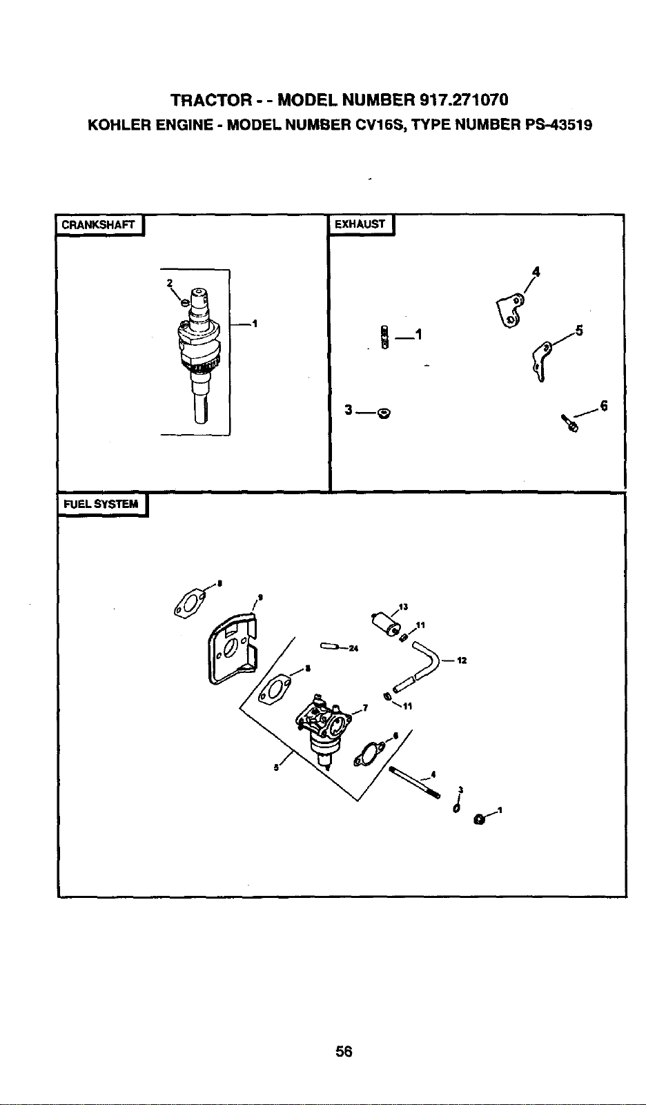
TRACTOR - - MODEL NUMBER 917.271070
KOHLER ENGINE - MODEL NUMBER CV16S, TYPE NUMBER PS-43519
CRANKSHAFT I
U
3 --_ _...16
FUEL SYSTEM I
56
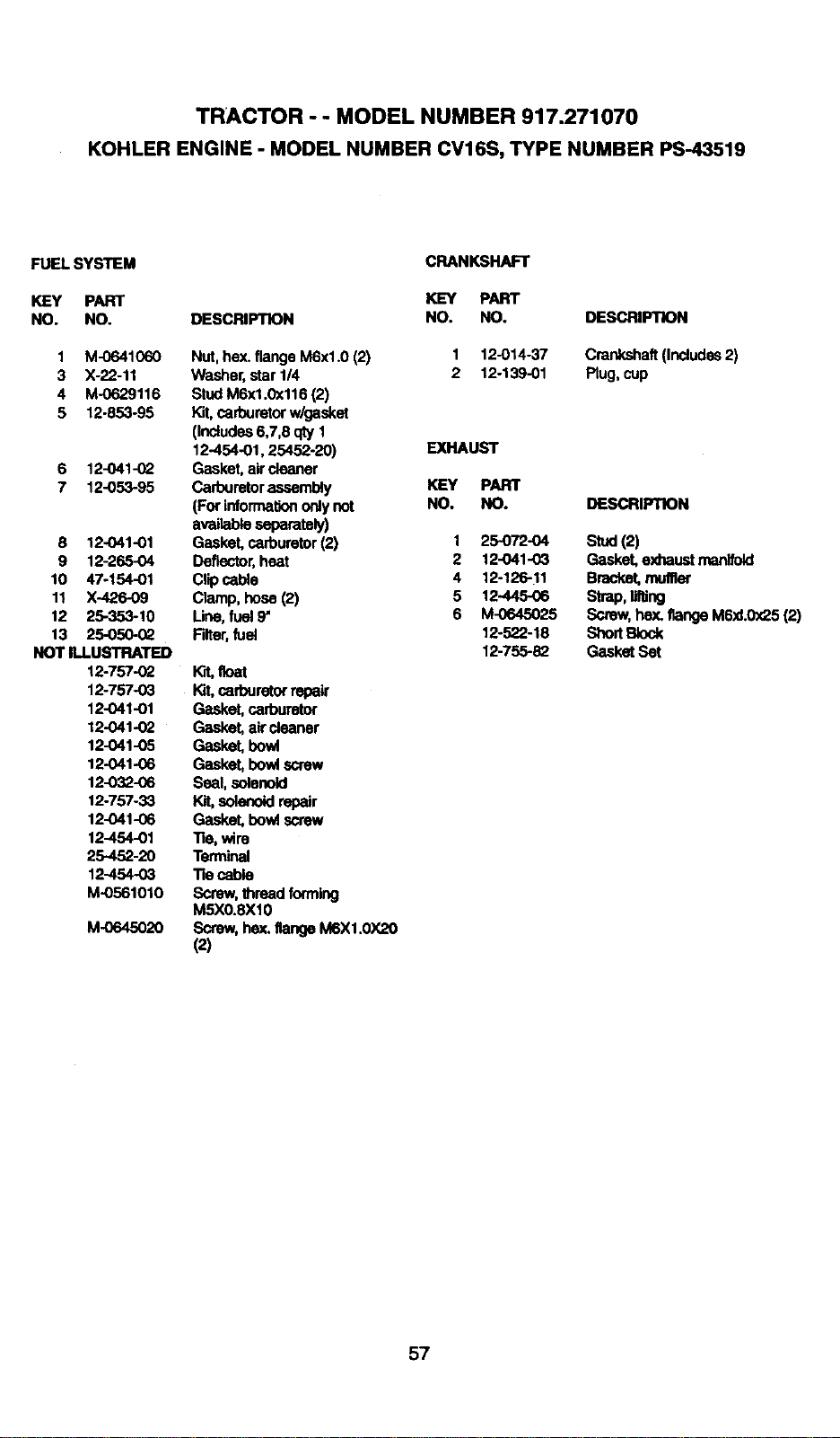
TRACTOR -- MODEL NUMBER 917.271070
KOHLERENGINE- MODELNUMBERCV16S,TYPENUMBERPS-43519
FUEL SYSTEM
KEY PART
NO, NO.
1 M-0641060
3 X-22-11
4 M.0629116
5 12-853-95
6 12.041-(_
7 12-053-95
8 12-041-01
9 12-265-04
10 47-154-01
11 X-426.09
12 25-353-10
13 25-050-(_
NOT ILLUSTRATED
12-757-02
12-757-03
12-041-01
12.041-(_
12-041-05
12-041-06
12-032-06
12-757-33
12-041-06
12-454-01
25-452-20
12-454-03
M-0561010
M.0645020
DESCRIPTION
Nut,hex.flangeM6xl.O(2)
Washer,star1/4
StudM6x1.0x116(2)
Kit,carburetorwlgasket
(Includes6,7,8qtyI
12454-01,25452-20)
Gasket,aircleaner
Carburetorassembly
(Forinformationonlynot
avaRableseparately)
Gasket,carburetor(2)
Deflector,heat
Clipcable
Clamp,hose(2)
I.ine,fuel9'
Filter,fuel
K_ fleat
K_ cafiouretorrepair
Gasket, carburetor
Gasket, air cleaner
Gasket, bowl
Gasket, bowl screw
Seal, solenoid
Kit,solenoidrepair
Gasket. bowi screw
Tie, wire
Temdnal
"Recable
Screw, threadforming
MSXO.SXIO
Screw, hex. flangeM6XI.0X20
(2)
CRANKSHAFT
KEY PART
NO. NO. DESCRIPTION
1 12-014-37 Crankshaft(Includes2)
2 12-139-01 Plug,cup
EXHAUST
KEY PART
NO. NO. DESCRIPTION
1 25-072-04 Stud (2)
2 12-041-03 Gesket,exhaust reanlfold
4 12-126-11 Bracket,muffler
5 12-445-06 Strap,lifting
6 M-0645025 Screw,hex. flangeMSxl.0x25(2)
12-522-18 ShortBlock
12-755-82 Gasket Set
57

58
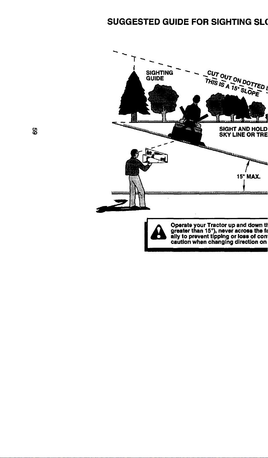
SUGGESTED GUIDE FOR SIGHTING SLOPES FOR SAFE OPERATION
" _
SIGHTING
ONLY RIDE UP AND DOWN HILL,
NOT ACROSS HILL
ol
co
15° MAX.
I
Operate your Tractor up and down the face of slopes (not I
greater than 15°), never across the face. Make turns gredu-
I
ally to prevent tipping or loss of control. Exercise extreme
caution when changing direction on elopes.

For in-home major brand repair service:
Call 24 hours a day, 7 days a week
1-800-4-MY-H OMEsM(1-800-469-4663)
Para pedir servicio de reparaci6n a domicilio
1-800-676-5811
In Canada for all your service and parts needs call
Au Canada pour tout le service ou les pi_ces
1-800-665-4455
For the repair or replacement parts you need:
Call 6 am-11pm CST, 7 days a week
PartsDirects"
1-800-366-PART (1-800-366-7278)
Para ordenar piezas con entrega a domicilio
1-800-659-7084
For the location of a Sears Parts and Repair Center
in your area:
Call 24 Hours a day, 7 days a week
1-800-488-1222
For information on purchasing a Sears Maintenance
Agreement or to inquire about an existing Agreement:
Call 9 am-5 pm, Monday - Saturday
1-800-827-6655
• SEARS •
HomeCentralsM
166998 02.04.99 RH Pdnted in U.S.A.