Ductless Multi-Split Heat Pump
Service Manual
• Please read this manual before using the heat pump.
• Keep this user manual for future reference.
PAGE 1
Table of Contents
2U18MS2HDA
3U24MS2HDA
4U36MS2HDA
ASH218JCDDA
ASH324JCDDA
ASH436JCDDA
Safety & Precautions ........................................................................................................................... 3
Electronic Controls ............................................................................................................................. 4
ENERGY STAR 6.1 Start-Up System Check .......................................................................................... 6
Sequence of Operation & Operational Parameters ............................................................................... 7
Error Codes & Troubleshooting ......................................................................................................... 19
Reference Information ...................................................................................................................... 35
PAGE 2
ENGLISH
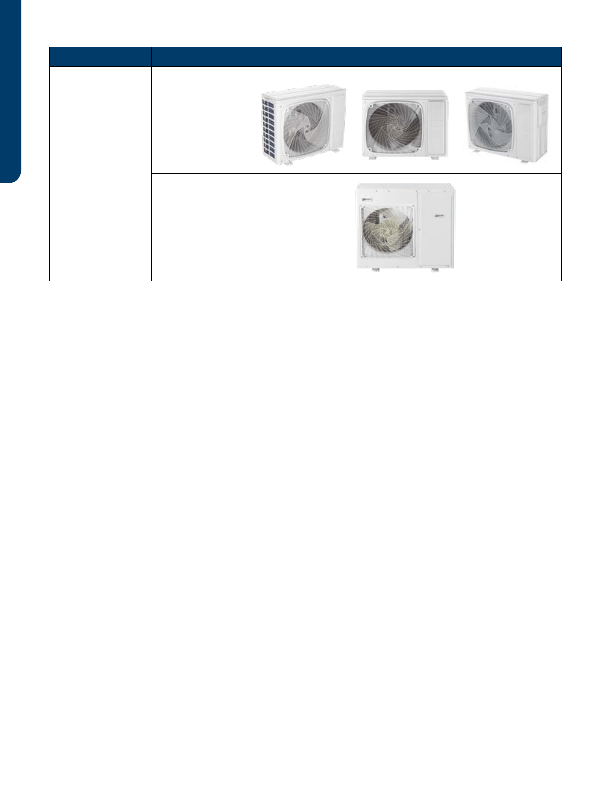
Type Model # Appearance
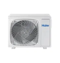
Outdoor Unit
2U18MS2HDA
3U24MS2HDA
ASH218JCDDA
ASH324JCDDA
4U36MS2HDA
ASH436JCDDA
SAFETY & PRECAUTIONS PAGE 3
ENGLISH
• Read these Safety Precautions carefully to ensure correct installation.
• This manual classies the precautions by WARNING and CAUTION.
• Follow all precautions below. They are all important for ensuring safety and preventing property/equipment damage.
!WARNING: Failure to follow any of WARNING is likely to result in grave consequences such as death or serious injury.
!CAUTION: Failure to follow any of CAUTION may, in some cases, result in grave consequences.
• The following safety symbols are used throughout this manual:
Observe this instruction Establish an earth connection Never attempt
• After completing installation, test the unit to check for installation errors. Give the user adequate instructions concerning the
use and cleaning of the unit according to the Operation Manual.
!WARNING
• Installation should be performed by the dealer or another professional.
Improper installation may cause water leakage, electrical shock, or re.
• Install the heat pump according to the instructions given in this manual.
Incomplete installation may cause water leakage, electrical shock, or re.
• Use only the supplied or specied installation parts.
Use of other parts may cause the unit to come lose, water leakage, electrical shock, or re.
• Install the heat pump on a solid base that can support the unit’s weight.
An inadequate base or incomplete installation may cause injury in the event the unit falls o the base.
• Electrical work should be carried out in accordance with the installation manual and national/local electrical wiring codes and
rules of practice.
Insucient capacity or incomplete electrical work may cause electrical shock or re.
• Use a dedicated power circuit. Never use a power supply shared by another appliance.
• For wiring, use a cable long enough to cover the entire distance with no splices.
Do not use an extension cord. Do not put other loads on the power supply, use a dedicated power circuit.
(Failure to do so may cause abnormal heat, electric shock or re.)
• Use only the specied wire types for electrical connections between the indoor and outdoor units.
Firmly clamp the interconnecting wires so they receive no external stresses. Incomplete connections or clamping may cause terminal over-
heating or re.
• After completing interconnecting and supply wiring connections, shape the cables so that they do not put undue force on the
electrical covers or panels.
Install covers over the wires. Incomplete cover installation may cause terminal overheating, electrical shock, or re.
• If any refrigerant has leaked out during the installation work, ventilate the room.
(The refrigerant produces a toxic gas if exposed to ame.)
• After all installation is complete, check for and repair any system refrigerant leaks.
(The refrigerant produces a toxic gas if exposed to ames.)
•When installing or relocating the system, keep the refrigerant circuit free from substances other than the specied
refrigerant (R410A), such as air.
(The presence of air or other foreign substance in the refrigerant circuit causes an abnormal pressure rise or rupture, resulting in injury.)
• During pump-down, stop the compressor before removing the refrigerant piping.
If the compressor is still running, and the stop valve is open during pump-down, air will be sucked into the system while the compressor is
running. This will cause abnormal pressure and noncondensables added to the system.
• Be sure to establish a ground. Do not ground the unit to a utility pipe, arrester, or telephone earth.
An complete earth may cause electrical shock, or re. A high surge current from lightning or other sources may
cause damage to the heat pumpheat pump.
!CAUTION
• Do not install the heat pump in a place where there is danger of exposure to ammable gas.
If the gas builds up around the unit, it may catch re.
• Install drain piping according to the instructions of this manual.
Inadequate piping may cause ooding.
•Tighten the are nut according to the specied torque using a torque wrench.
If the are nut is overtightened, the are nut may eventually crack and cause refrigerant leakage.
• Provide adequate measures to prevent the outdoor unit from being used as a shelter by rodents.
Rodents making contact with electrical parts can cause malfunctions, smoke or re. Please instruct the customer to keep the area around
the unit clean.
Safety & Precautions
ELECTRONIC CONTROLS
PAGE 4
ENGLISH
The outdoor unit features a variable speed, rotary type compressor that delivers refrigerant
ow to up to 4 individual indoor units. The system uses R-410A refrigerant mixed with PVE
oil, and is 208/230 VAC, 60 Hz, single phase.
Compatible indoor units are High wall, Cassette, and Ducted with remote control, cassette
with either remote or wired control, and ducted with wired control only.
The indoor units will maintain individualized room temperatures as set on each controller,
provided all units are in the same mode. If the rst unit to be turned on is set to the heating
mode, all units will heat. If the rst unit to be turned on is set to the cooling mode, all units will
cool.
2
4
3
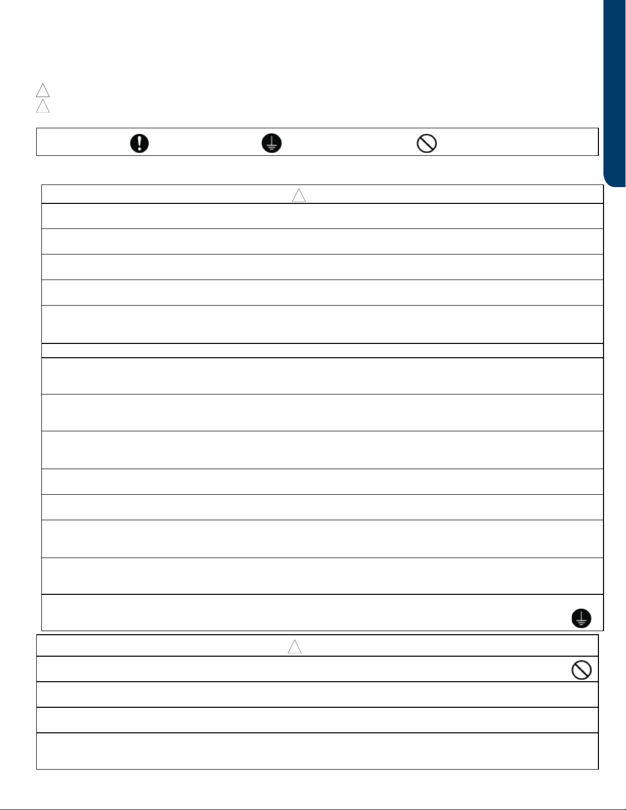
1The SMB is connected to the PCB via connections CN-2 and CN-3.
The SW1 DIP switches are OFF (default position for normal operation).
The digital display will indicate operating frequency of the compressor when no
error code is present, or will ash an error code if present.
A solid green LED indicates that the A, B, C, D or E unit is successfully
communicating with the outdoor unit.
The SMB has important features including operational DIP switches, error code display, compressor speed, and diagnostic
capabilities.
2
4
1
3
2
3
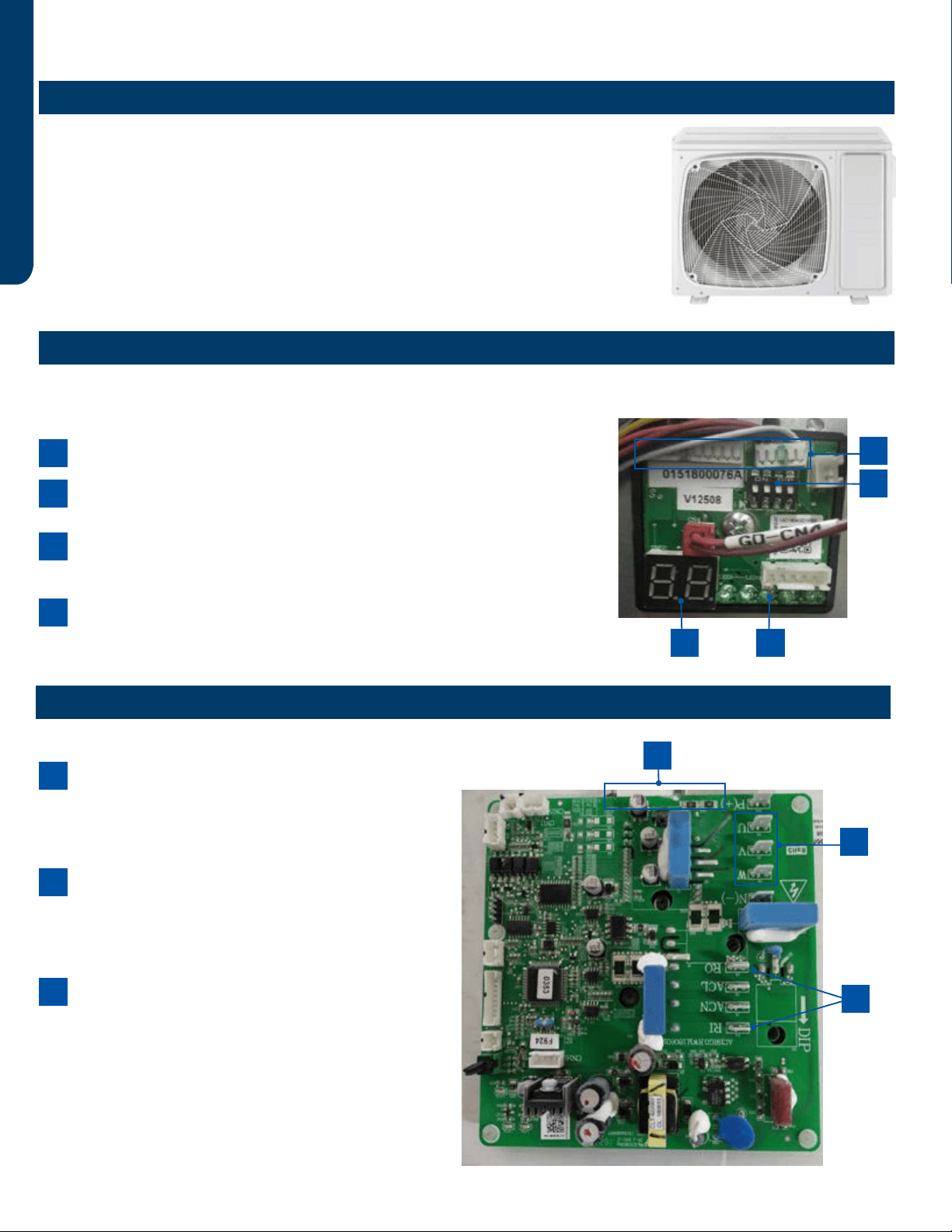
1The Inverter Power Module generates 3-phase VAC
power to operate the variable speed compressor. The
compressor is connected to the IPM via terminals U, V
and W.
A Reactor Coil is connected to the IPM at terminals
RI and RO. The Reactor Coil will lter electrical noise
generated at high frequency operation that could
cause damage to the compressor windings.
IPM generates a large amount of heat during operation.
This heat is transfered to a heat sink behind the board,
then mixed with the outdoor air. The Tm temperature
sensor protects the IPM from excessive temperatures.
2
1
3
Electronic Controls
Outdoor Unit Introduction
Service Monitor Board (SMB) Overview
Inverter Power Module (IPM) Overview
ELECTRONIC CONTROLS PAGE 5
ENGLISH
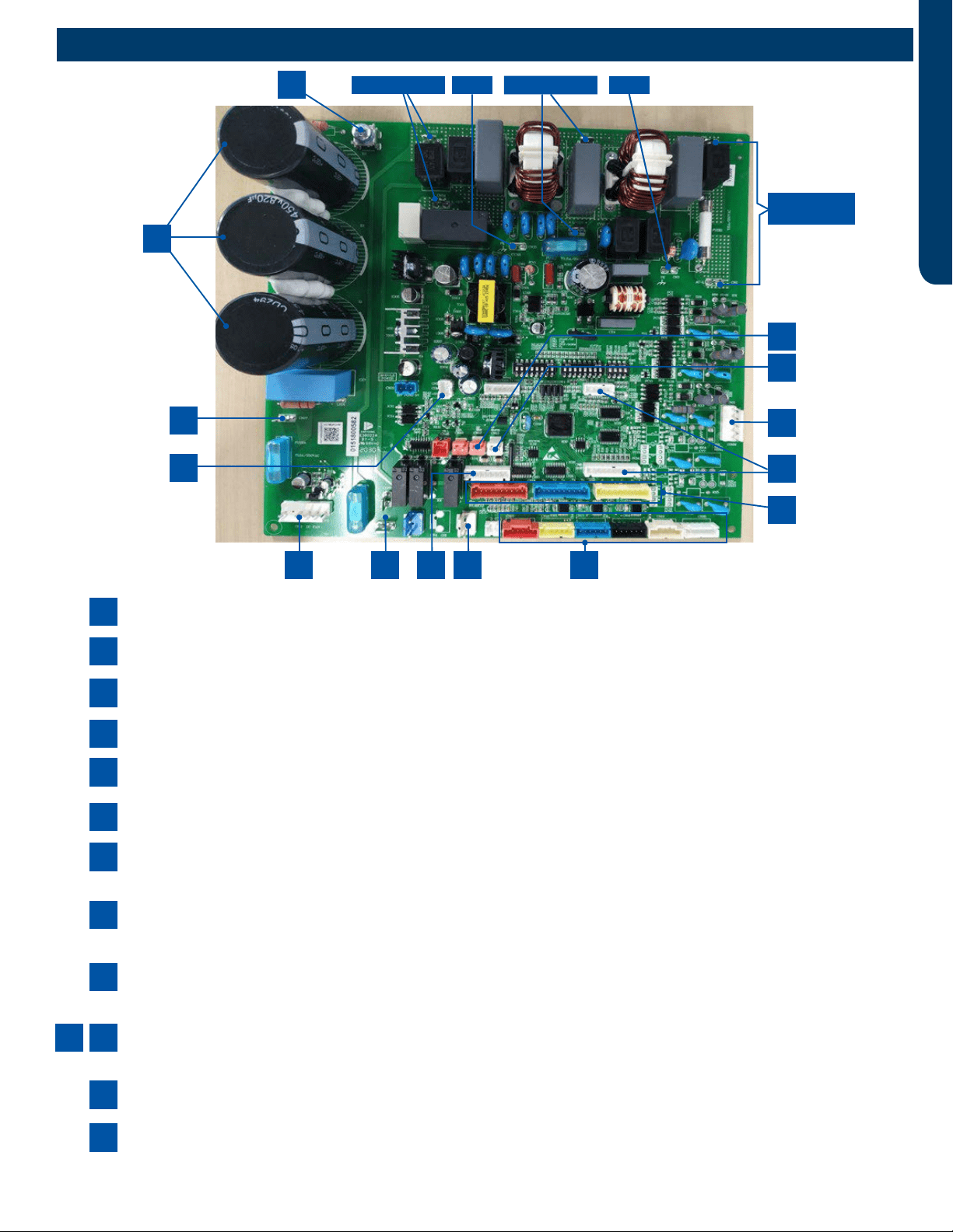
CN26/CN27--Reactor lter the harmonic in the current, it connects to main PCB via CN26 and CN27.
There will only be 2 capacitors on the board, not 3 as shown.
CN9--Communication port between main control board and module board.
CN11--The Outdoor Fan Motor is a DC voltage, variable speed type.
CN8/CN9--The Crankcase Heater is energized via a connection at terminals CN-9 and CN-8 on the PCB.
CN47--The RJ45 is a small board that connects the PC and the main control board for the use of GE3.0 port.
CN5--The 4-Way Valve is energized by line voltage from a connection via Plug CN-5. This valve is energized in HEAT
MODE.
CN15-CN18--The EEV coils for the outdoor unit and each indoor unit are connected at terminals CN-15 through CN-
18. These EEV coils include the connection for the HEAT MODE EEV coil.
CN14/CN24/CN25-- There are system temperature sensors that monitor refrigerant line temperature and outdoor
air temperatures, and the temperature of the refrigerant entering and leaving each circuit.
CN12/CN13--The system has two refrigerant pressure switches, a Low Pressure Switch and a High Pressure Switch.
These switches are connected to the PCB via Plugs CN-12(HP) and CN-13(LP).
CN21--Plug CN-21 connects the data path between each indoor unit and the PCB.
CN8/CN23--The Service Monitor Board connects to plugs CN-23 and CN-8. When these cables are connected to the
Service Monitor Board, the SMB digital display should be illuminated.
2
10
6
4
12
8
7
3
11
9
5
13
1
1Module Power Internal PowerGND GND
Main Control
Board Power
12
13
10
11
2
1
3
4 5 7 86
9
PCB Overview
2U18MS2HDA
3U24MS2HDA
4U36MS2HDA
ASH218JCDDA
ASH324JCDDA
ASH436JCDDA
START-UP SYSTEM CHECK
PAGE 6
ENGLISH
All new ENERGY STAR certied product lines released as of
February of 2022 will comply with the new 6.1 standards (see
ENERGY STAR 6.1 requirements). When the system is rst
powered up after installation, the system will now perform a
start-up system check. See the following sequence of opera-
tion:
1. Indoor and outdoor units with ‘88’ displays, will have ‘CC’
displayed for 5 seconds.
2a. When the outdoor ambient temperature is 14~75°F
(-10~24°C), the system will run heating and cooling mode for
10 minutes each, the indoor and our door display will show ‘n2’
and ‘n3’ accordingly.
2b. When the outdoor ambient temperature is -4~14°F
(-20~10°C), the system will only run heating mode for 15 min-
utes, indoor and outdoor display will show ‘n2’.
2c. When the outdoor ambient temperature is 75~115°F
(-24~46°C), the system will only run cooling mode for 15 min-
utes, indoor and outdoor display will show ‘n3’.
3. Upon nishing and passing all test, the indoor and outdoor
display will show ‘PS’. The unit can now be used normally.
If the system does not pass any of the checks, the indoor and
outdoor display will show an error code and the testing will
stop. Please refer to the service manual for this model to cor-
rect the error. The automatic testing will need to be manually
initiated by following the steps:
Set the remote controller to Cool, High Fan speed, 60°F (16°C),
and then press the ‘Sleep’ button 4 times within 5 seconds.
The indoor will beep 5 times and display ‘CC’ and run the same
tests as above.
NOTE: The system may display erroneous error codes when
outdoor ambient temperature is below -4°F or above 115°F.
When these conditions exist the start-up test may be by-
passed and rescheduled for a time when outdoor tempera-
tures return to more favorable conditions. NOTE: When the
outdoor control board has been replaced for service reasons,
the start-up test may be bypassed.
Bypassing start-up test: Within 5 seconds of applying power
to the system, while ‘CC’ is displayed on the indoor, set the
indoor to Dry and 68°F (20°C). The indoor display will change
to ‘BP’ for 5 seconds then go into stand-by mode. The unit can
then be used normally.
NOTE: The start-up test cannot be bypassed if the display
reads ‘n2’ or ‘n3’. The power may be cycled prior to nishing
the test and another attempt can be made to bypass.
Run the system for 20 minutes to check the parameters’
range per table below.
ENERGY STAR 6.1 Start-Up System Check
Model Mode Check parameters
Suction
temp.
Exhaust
temp.
IDU coil
temp
IDU outlet
temp.
2U18MS2HDA
ASH218JCDDA
Cooling
Ambient temp < 50F 46-64°°F 86-122°F 52-63°F 54-64°F
50F < Ambient temp < 86F 50-68°F 95-158°F 52-63°F 54-64°F
Ambient >86F 54-68°F 104-185°F 52-68°F 52-70°F
Heating
Ambient temp 23F 0-19°F 102-131°F 81-88°F 75-84°F
23F < Ambient temp < 50F 21-45°F 104-167°F 82-100°F 79-93°F
Ambient >50F 41-75°F 104-185°F 86-115°F 86-100°F
3U24MS2HDA
ASH324JCDDA
Cooling
Ambient temp < 50F 46-64°F 86-122°F 52-63°F 54-64°F
50F < Ambient temp < 86F 50-68°F 95-158°F 52-63°F 54-64°F
Ambient >86F 54-68°F 104-185°F 52-68°F 52-70°F
Heating
Ambient temp 23F 0-14°F 95-140°F 79-97°F 79-93°F
23F < Ambient temp < 50F 14-45°F 104-158°F 86-102°F 82-100°F
Ambient >50F 32-77°F 131-176°F 90-113°F 86-109°F
SEQUENCE OF OPERATION & OPERATIONAL PARAMETERS PAGE 7
ENGLISH
Sequence of Operation & Operational Parameters
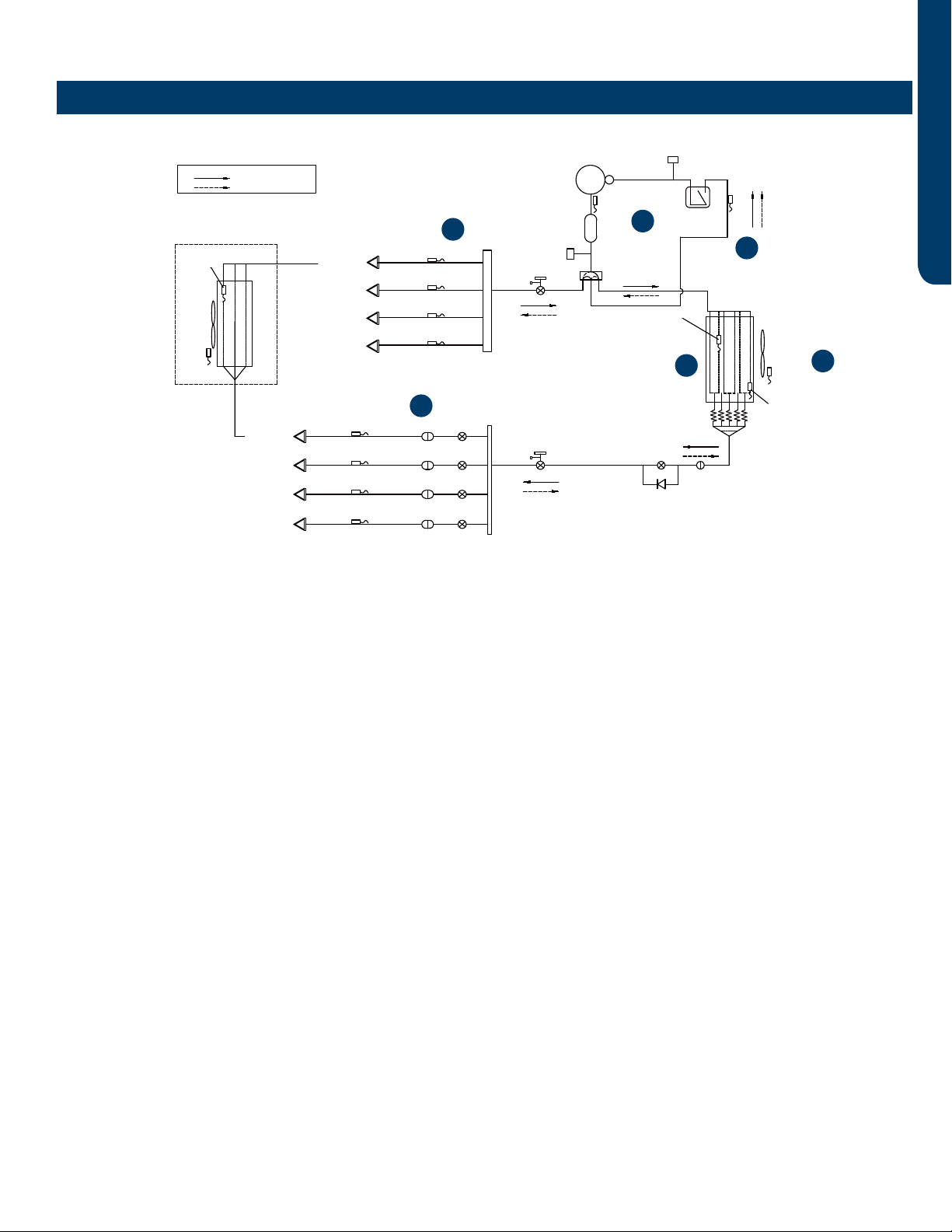
On a call for cooling, the indoor unit will send the room temperature and set-point requirement to the outdoor unit PCB via the
data signal wire path. The indoor louvers will open and the indoor fan motor will start.
The outdoor unit will energize the EEVs that are controlling refrigerant ow to the calling indoor units. The position of the EEVs
will be set to an initial position based upon the outdoor air temperature.
The 4-way valve is de-energized. After a 3-minute time delay, the outdoor fan motor will be energized. Shortly after the outdoor
fan motor turns on, the compressor will start in low frequency. The operating frequency of the compressor will be displayed on
the Service Monitor Board.
Comp-
ressor
Discharge temp.
sensor
High pressure
swtich
4-way valve
Muffler
Gas-liquid
separator
.pmet noitcuS
rosnes
Low pressure
switch
Gas stop valve
Outdoor
heat
exchanger
temp.
sensor
FAN-OUT
Outdoor
ambient
temperature
sensor
Defrost
sensor
Distributor
Strainer
EEV O
Check valve
Liquid stop valve
5/8
3/8
EEV A
Strainer
Unit A liquid pipe temp. sensor
Indoor unit A
EEV B
Strainer
Unit B liquid pipe temp. sensor
Indoor unit B
EEV C
Strainer
Unit C liquid pipe temp. sensor
Indoor unit C
Indoor unit D
EEV D
Strainer
Unit D liquid pipe temp. sensor
Unit A gas pipe temp. sensor
Unit B gas pipe temp. sensor
Unit C gas pipe temp. sensor
Indoor unit A
Indoor unit B
Indoor unit C
Unit D gas pipe temp. sensor
Indoor unit D
4-way valve coil:
OFF
ON
Refrigerant flow in cooling
Refrigerant flow in heating
FAN-IN
Indoor
ambient
temperature
sensor
Indoor
heat
exchanger
temp.
sensor
1
23
4
6
5
Cooling Mode Sequence of Operation

SEQUENCE OF OPERATION & OPERATIONAL PARAMETERS
PAGE 8
ENGLISH
1 Temperature Sensor Td
The temperature of the compressor discharge hot gas will be
monitored by the Discharge Temperature Sensor. If the sen-
sor reads too hot or cool, the frequency/status of the opera-
tion will be adjusted accordingly.
The hot gas will leave the oil separator and enter the 4-way
valve, which directs the hot gas to the outdoor coil. The refrig-
erant will condense in the outdoor coil and be subcooled. The
refrigerant is now in a liquid state.
2 Temperature Sensor Tc
This sensor monitors the temperature of the outdoor coil
during condensing operation. If abnormal condensing tem-
perature is detected, the outdoor fan motor speed or com-
pressor frequency may be adjusted.
3 Temperature Sensor Ta
The outdoor air temperature will be monitored by the PCB.
If the outdoor air temperature rises or falls, the speed of the
outdoor fan may be changed.
4 Temperature Sensor Tc2
The Liquid Pipe Sensor will monitor the temperature of the
refrigerant leaving the EEV.
The low pressure low temperature refrigerant will enter the
mixed phase liquid line and travel to the indoor unit. Heat from
the indoor air passing across the evaporator coil will transfer
to the cold refrigerant, sending cool air into the space and
changing the liquid refrigerant into a cool vapor.
The cold vapor will travel down the vapor line and return to the
outdoor unit via a path through the gas stop valve.
5 Temperature Sensor Tc1
The Gas Pipe Sensor will monitor the temperature of the gas
pipe to calculate the dierence between Liquid Pipe Tem-
perature and Gas Pipe Temperature. If a change in EEV port
opening size is needed, the EEV will make a small adjustment.
The vaporized refrigerant enters the 4-way valve and travels
to the vapor line accumulator. The accumulator will trap any
liquid refrigerant if present to prevent it from entering the
compressor.
The vapor will exit the accumulator and enter the compressor.
This cycle will repeat until the demand for cooling ends.
6 Temperature Sensor Ts
The temperature of the suction gas entering the compres-
sor is monitored by the Suction Temperature Sensor. Before
stopping operation, the EEV may open to feed more refriger-
ant or close to warm up the line.
The demand becomes less as the indoor temperature drops
toward the desired temperature, so the compressor will
reduce speed. When the set temperature is reached, the
compressor and outdoor fan will shut o. The circulating fan
of each indoor unit continues to run.
Cooling Mode Sequence of Operation

SEQUENCE OF OPERATION & OPERATIONAL PARAMETERS PAGE 9
ENGLISH
Comp-
ressor
Discharge temp.
sensor
High pressure
swtich
4-way valve
Muffler
Gas-liquid
separator
.pmet noitcuS
rosnes
Low pressure
switch
Gas stop valve
Outdoor
heat
exchanger
temp.
sensor
FAN-OUT
Outdoor
ambient
temperature
sensor
Defrost
sensor
Distributor
Strainer
EEV O
Check valve
Liquid stop valve
5/8
3/8
EEV A
Strainer
Unit A liquid pipe temp. sensor
Indoor unit A
EEV B
Strainer
Unit B liquid pipe temp. sensor
Indoor unit B
EEV C
Strainer
Unit C liquid pipe temp. sensor
Indoor unit C
Indoor unit D
EEV D
Strainer
Unit D liquid pipe temp. sensor
Unit A gas pipe temp. sensor
Unit B gas pipe temp. sensor
Unit C gas pipe temp. sensor
Indoor unit A
Indoor unit B
Indoor unit C
Unit D gas pipe temp. sensor
Indoor unit D
4-way valve coil:
OFF
ON
Refrigerant flow in cooling
Refrigerant flow in heating
FAN-IN
Indoor
ambient
temperature
sensor
Indoor
heat
exchanger
temp.
sensor
On a call for heating, the indoor unit will send the room temperature and set-point requirement to the outdoor unit PCB via the
data signal wire path. The indoor unit louvers will open. The fan will not start until the coil has warmed suciently to avoid cold
drafts.
EEVs serving indoor circuits will step to the standard opening. The outdoor EEV opens to a position based upon the outdoor air
temperature.
The 4-way valve will energize and the outdoor fan will start. The compressor starts at a slow speed and will increase based upon
demand. The indoor fan starts after the indoor coil is warm enough to avoid circulating cool air.
With the compressor operating, refrigerant will begin to ow throughout the refrigeration circuit.
The operating frequency of the compressor will be displayed on the Service Monitor Board.
1
2
3
4
5
2
Heating Mode Sequence of Operation
SEQUENCE OF OPERATION & OPERATIONAL PARAMETERS
PAGE 10
ENGLISH
1 Temperature Sensor Td
The temperature of the compressor discharge hot gas will
be monitored by the Discharge Temperature Sensor. If the
sensor reads too hot or cool, the frequency/status of the
operation will be adjusted as needed.
The hot gas will leave the oil separator and enter the 4-way
valve. The 4-way valve will direct the hot gas to ALL of the
indoor coils.
Note: Any indoor unit that is in heating mode will have it’s louver
open and indoor fan running. Non-calling indoor units will receive
hot gas but their fans will remain on very low speed with the
louver open. When demand for heat increases, the indoor fan will
speed up to meet the increased demand.
2 Temp. Sensor Tc1 & Indoor Heat Exchanger Temp. Sensor
The temperature of Tc1 should now be hot. This will indicate
the 4-way valve is directing hot gas to the indoor coils. If it is
not, there is a problem with the 4-way valve. The PCB will de-
tect the temperature dierence and generate an Error Code.
The indoor heat exchanger temperature sensor will monitor
the temperature of the indoor coil to ensure it is hot
enough to prevent blowing cold air. Once adequately warm
temperature is sensed at the indoor coil, the PCB will increase
the fan speed if needed to meet the demand.
The hot gas entering the indoor coil will condense into a
saturated mix and then be subcooled. The refrigerant will
return to the outdoor unit via the liquid line.
3 Temperature Sensor Tc2
This sensor monitors the temperature of the refrigerant liquid
returning from the indoor coil. The indoor EEV opening angle
is xed.
The liquid will enter the Liquid Line Strainer and will pass
through the OPEN EEV.
The refrigerant liquid now enters a receiver where excess
refrigerant will be stored.
After the liquid leaves the Liquid Receiver, it will enter the
restriction of the OUTDOOR UNIT’s EEV, which changes the
liquid refrigerant to a lower pressure and temperature as it
enters the outdoor coil.
As the outdoor coil absorbs heat from the surrounding air,
the very cold liquid refrigerant boils o and changes to a
superheated vapor. This vapor travels through the 4-way
valve to the accumulator.
4 Temperature Sensor Te
The outdoor coil temperature will be sensed by the Defrost
Sensor. The sensor will use this temperature to adjust EEV
open angle and to calculate when a defrost cycle is necessary.
5 Temperature Sensor Ts
The temperature of the suction gas entering the compressor
is monitored by the Suction Temperature Sensor.
As the demand becomes less while the indoor temperature
rises toward the desired temperature, the compressor will
reduce speed. The compressor and outdoor fan will shut o
when the set temperature is reached. The circulating fan of
each indoor unit continues to run.
Heating Mode Sequence of Operation
SEQUENCE OF OPERATION & OPERATIONAL PARAMETERS PAGE 11
ENGLISH
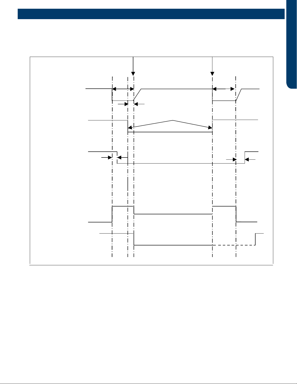
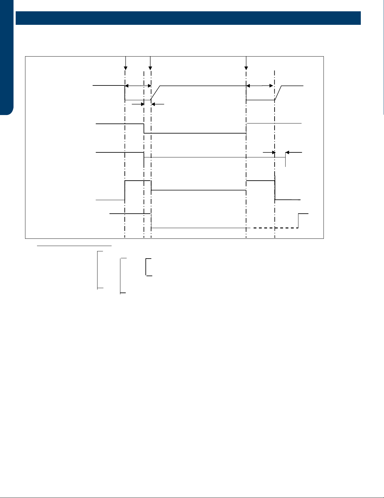
Beginningend
Fixed frequencyIndicated FQY 60sDefrosting FQY A (E)60s Soft startup
Compressor
0HZ 0HZ
5s
Outdoor motor ON Send defrosting signal to indoorAuto
OFF
4-way valve ON
OFF50s
450-pulse450-pulse
300-pulse(E)
All EEVs Auto open angleAuto open angle
All indoor motors ON
OFFAnti-cold air function
Multi:
5s
Defrost Cycle Sequence of Operation
SEQUENCE OF OPERATION & OPERATIONAL PARAMETERS
PAGE 12
ENGLISH
Electronic Expansion Valve (EEV) Control
Electronic characteristics
Max. open angle 480 pulses
Driving speed PPS
Open angle limitation of EEV
Unit stop Max. open angle Thermostat OFF Min. open angle
Cool/ dry 5 pulses 470 pulses 5 pulses 80 pulses
Heat 50 pulses 470 pulses 50 pulses 80 pulses
The EEV routinely opens and closes to maintain the compressor discharge temperature within an acceptable range.
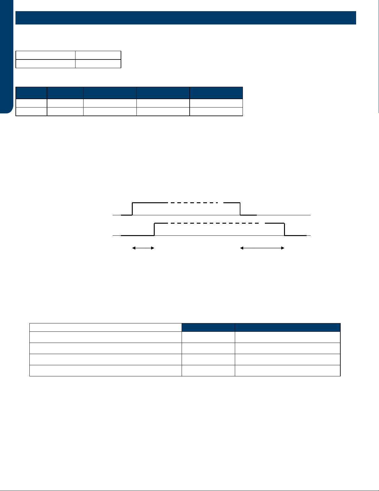
c
ompressor ON
OFF
4
-way valve ON
OFF
50S 2 minutes and 55s
4-Way Valve Heating Control
There is a 1-minute delay before power is applied to the 4-way valve to switch the flow of hot refrigerant to the indoor coil when
the compressor starts in the heating mode. A 3-minute delay will occur before the 4-way valve is powered down and switches
back to the at-rest (cooling) position when the call for heat is satisfied and the compressor shuts off.
After 15 minutes of compressor run time and the indoor coil temperature is below 41°F/5°C, the compressor will stop and the
unit will display a 17-flash error code on the outdoor PCB if the 4-way valve does not switch into the heating mode.
Compressor Sump Heater
The sump (crankcase) heater keeps refrigerant at a higher temperature than the coldest part of the system. This prevents
refrigerant from mixing with the compressor oil and also dries condensed refrigerant inside the sump. The sump heater will be
energized when the ambient temperature is below 81°F/27°C and will be off when the ambient is 90°F/32°C.
Heater OFF Heater ON*min
Ta>50OF(10OC) OR Td>=68OF(20OC) 100%*60min 0
41OF(5 OC<Ta ≤50OF(10OC)and Td<68OF(20OC) 50%*60min 50%*60min
32OF(0OC)<Ta ≤41OF(5 OC)and Td<68OF(20OC) 33%*60min 66%*60min
32OF(0OC)>=Ta andTd<68OF(20OC) 0100%*60min
Operating Parameters
SEQUENCE OF OPERATION & OPERATIONAL PARAMETERS PAGE 13
ENGLISH
Base Pan Heater Control Logic
When the compressor starts in the heating mode, the following conditions will apply:
Troubleshooting the base pan heater error:
STEP1: Check the pan heater for an open circuit or shirt circuit. Unplug the connector from main control PCB. Test the
resistance between the two pins of the pan heater connector. It should be 0.28-0.379KΩ. If out of range, change the pan heater.
If normal go step 2.
STEP 2: Check the main control board pan heater output port . Unplug the connector from main control PCB. Run the ODU with
manually forced heating (Set the display board SW 1-1 as ON). Test the voltage between the two pins at CN4, it should be 208-
230Vac.
Defrost Control
In the heating mode and along with the ambient sensor, the defrost sensor monitors the temperature of the outdoor coil to
determine if defrost is needed. If the compressor has been running for 10 minutes continuously and for 45 minutes overall, the
difference between the ambient sensor (Ta) and the defrost sensor (Te) will be checked. The system will initiate the defrost cycle
if the following conditions can be met for 5 continuous minutes:
Te ≤ C x Ta-A
Te: Defrost temperature sensor
Ta: Ambient temperature
C: 0.80 if Ta < 32°F/0°C 0.60 if Ta ≥ 32°F/0°C
A: 8, moderate climate (factory setting) 6, severe climate (alternate setting)
End defrosting: The defrost cycle will terminate if the defrost sensor (Te) detects the temperature of the outdoor coil is above
44oF(7oC) for 60 seconds or is above 54oF(12oC) for 30 seconds. The defrost cycle will automatically terminate in 10 minutes if
these temperatures cannot be reached.
Timed defrost option:
• When the outdoor ambient temperature sensor detects Ta is less than 32oF(0oC)
• In heating mode, compressor runs continuously for 60 minutes or for 240 minutes in all.
The system will defrost when the above conditions are met. Defrosting frequency is 68 HZ, with a defrosting time of 8 minutes.
Outdoor Temperature Pan Heater
>37oF(3oC) OFF
28oF(-2oC) to 34oF(1oC) OFF 20min. ON 10min.
10oF(-12oC) to 25oF(-4oC) OFF 15min. ON 15min.
<10oF(-12oC) ON
Operating Parameters
SEQUENCE OF OPERATION & OPERATIONAL PARAMETERS
PAGE 14
ENGLISH
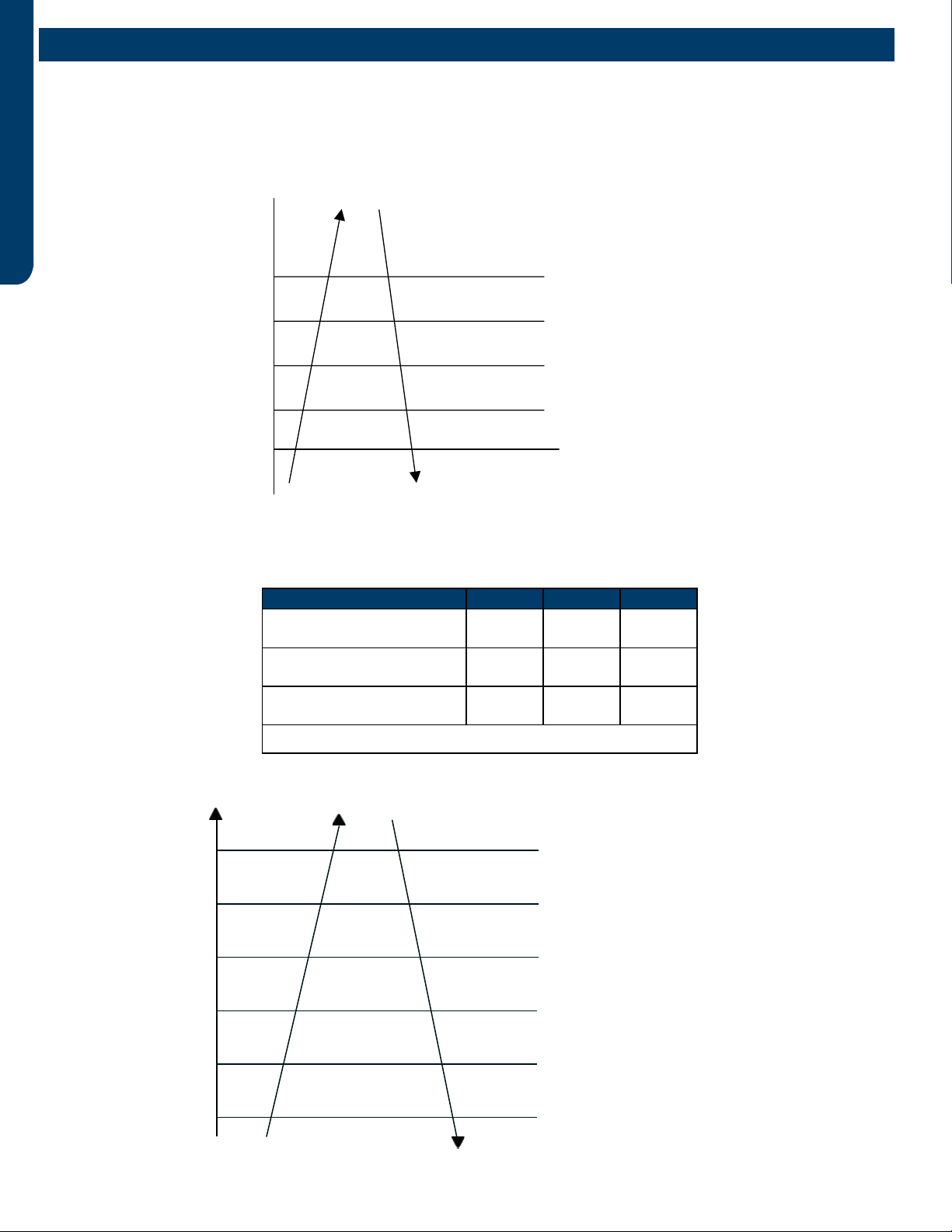
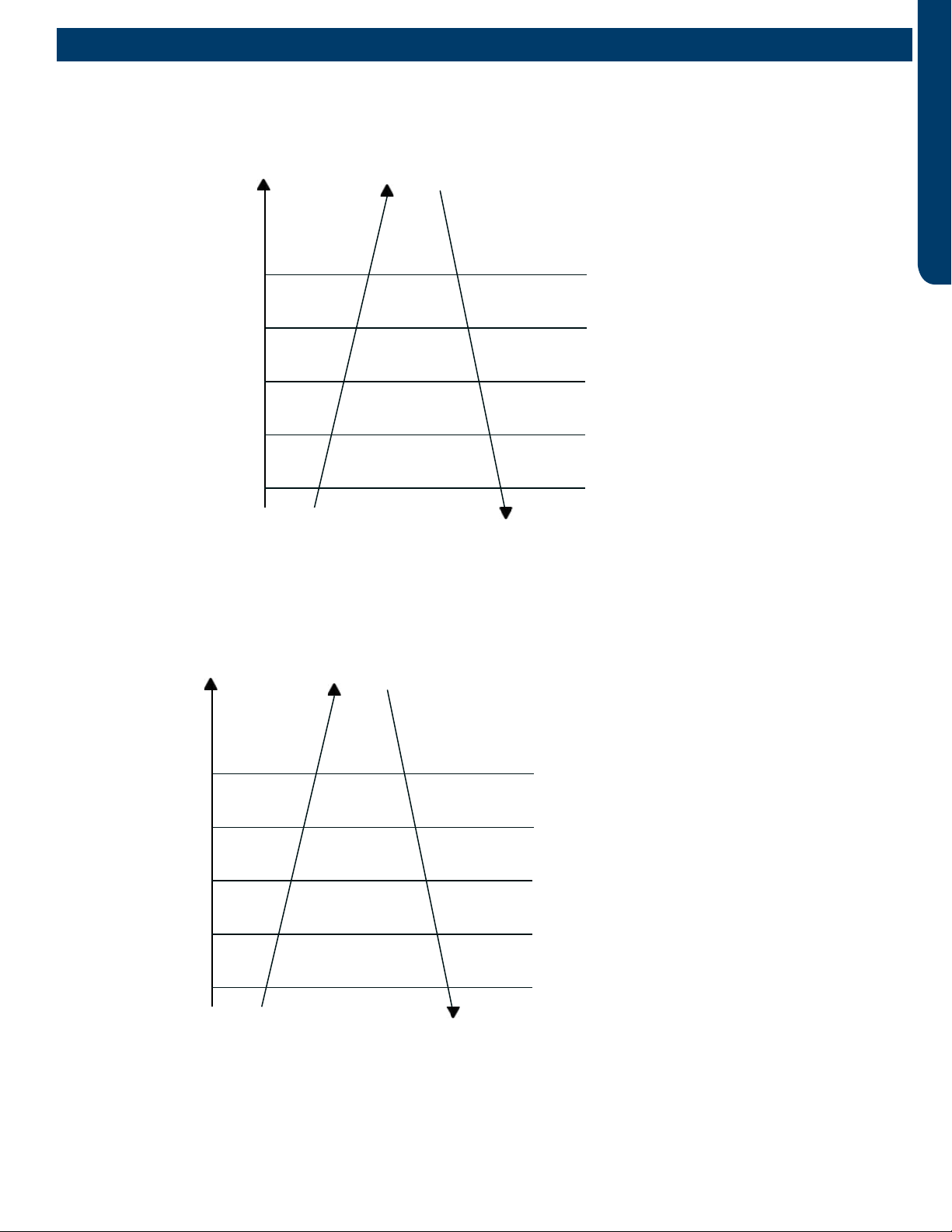
Discharging t
emp.
Td
Reduce FQY rapidly 2HZ/S
Reduce FQY rapidly 1HZ/S
Reduce FQY slowly 1HZ/10S
Remain FQY
Increase FQY slowly 1HZ/10S
118℃
115℃
112℃
109℃
105℃
95℃
Unitary:
Multi:
Discharging temp. Td
Reduce FQY rapidly 1HZ/S
Reduce FQY slowly 1HZ/10S
Remain FQY
Increase FQY slowly 1HZ/10S
If keeping for 10s, the unit stops, 3 minutes later, the unit can
re-startup. If in 60 minutesthe unit occurs alarm for 3 times, the
failure can be eliminated.
Remain FQY
The compressor will shut off if the discharge temperature
sensor reaches 243F for 10 seconds. The compressor
will restart after the 3-minute time delay. The compressor
will lock out if this occurs three times in a 60-minute
period. The compressor will not restart until the power is
interrupted then restored until the cause of the high
temperature is discovered.
203℉( 95℃)
207℉( 97℃)
225℉( 107℃)
234℉( 112℃)
243℉( 117℃)
Discharge Sensor Protection
If the discharge temperature is higher than normal, the compressor will slow down to lower the temperature.
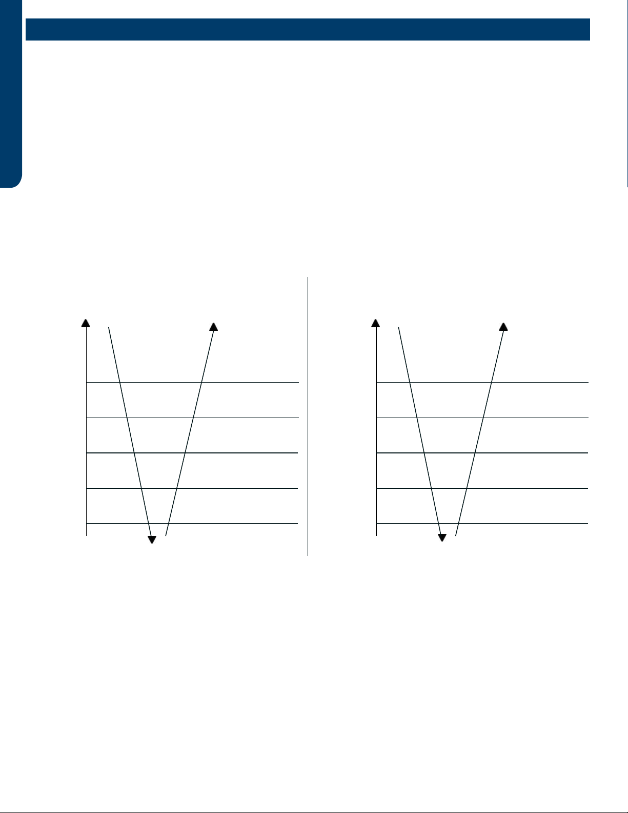
High Current Protection
The following table lists the outdoor unit and compressor current protection levels.
The system will lock out if the temperature reaches
150OF(66OC) three times in one hour. Reset by
turning power off and back on.
Reduce FQY rapidly 2Hz/S
Reduce FQY rapidly 1Hz/S
Reduce FQY rapidly 1Hz/10S
Remain FQY
Reduce FQY slowly 1Hz/S
100%*I
98%*I
96%*I
96%*I
90%*I
88%*I
Remain FQY
Model MCA MOP CT
2U18MS2HDA
ASH218JCDDA 19.0A 30A 15.5A
3U24MS2HDA
ASH324JCDDA 22.0A 30A 15.5A
4U36MS2HDA
ASH436JCDDA 26.0A 30A 15.5A
Note: The compressor current is for reference only, and the actual installation should
reference the maximum current value.
Operating Parameters
SEQUENCE OF OPERATION & OPERATIONAL PARAMETERS PAGE 15
ENGLISH
High Pressure Protection
High Pressure Protection in Cooling
The unit will turn off if there is an abnormal stop three
times in one hour. Turn off and restore power to clear
error.
Reduce FQY rapidly 2Hz/S
Reduce FQY slowly 1Hz/S
Remain FQY
Raise FQY slowly 1Hz/10S
131OF(55OC)
Tc--cooling
138OF(59OC)
144OF(62OC)
147OF(64OC)
150OF(66OC)
Remain FQY
High Pressure Protection In Heating
The system will lock out if the temperature reaches 158OF(70OC) three
times in one hour. Reset by turning power off and back on.
Reduce FQY rapidly 2Hz/S
Reduce FQY slowly 1Hz/10S
Remain FQY
Raise FQY slowly 1Hz/10S
129OF(54OC)
Tc--heating
135OF(57OC)
138OF(59OC)
145OF(63OC)
158OF(70OC)
Remain FQY
Operating Parameters
SEQUENCE OF OPERATION & OPERATIONAL PARAMETERS
PAGE 16
ENGLISH
Low Pressure Protection
The compressor will stop running if the low pressure switch opens for one minute.
The compressor will lock out and a low pressure error code will be displayed at the indoor unit if this condition occurs 3 times in an
hour. A low pressure error code will be displayed if the compressor is not running and the switch opens for 30 seconds.
The low pressure switch does not stop compressor operation or signal an error code during the following conditions:
• The rst 8 minutes of run time when the compressor starts a new cycle
• During defrost
• When the ambient temperature is below 32°F/0°C
• Following the termination of an oil return cycle
Low pressure protection is provided by the coil temperature sensors in both heating (Te) and cooling (Tc2) modes when any of
the above 4 conditions are present.
Operate normally
Min. running FQY 20Hz
LP OFF & FQY 20Hz
LP ON & FQY 20Hz
Raise FQY slowly 1Hz/10S
-49OF(-45OC)
Tc 2
-40OF(-40OC)
-31OF(-35OC)
-22OF(-30OC)
-13OF(-25OC)
Low Pressure Protection in Heating Mode:
Operate normally
Min. running FQY 20Hz
LP OFF & FQY 20Hz
LP ON & FQY 20Hz
Raise FQY slowly 1Hz/10S
-49OF(-45OC)
Te
-40OF(-40OC)
-31OF(-35OC)
-22OF(-30OC)
-58OF(-45OC)
Low Pressure Protection in Cooling Mode:
Operating Parameters

SEQUENCE OF OPERATION & OPERATIONAL PARAMETERS PAGE 17
ENGLISH
Send oil return signal oil return begins oil return over
60s ref. eliminated 30s
Oil return frequency auto frequency
Low frequency
Inverter compressor auto frequency
350 pulses(E)
running indoor EEV auto angle auto angle
120 pulses(E)
80(E)
stopped indoor EEV OFF angle 5(E) OFF angle 5(E)
Outdoor motor AUTO AUTO (TC or ambient temp. control) AUTO
running indoor motor AUTO AUTO (set fan speed) AUTO
stopped indoor motor STOP STOP STOP
4-way valve OFF OFF OFF
MULTI:
D: Entering Conditions
When the compressor running frequency is lower than 58Hz (E) continuously for 8 hrs, the system
will enter the oil return cycle.. In the course of mode changeover, manual unit stop or protective
unit stop, the time will be accumulative. After the compressor restarts up, the time will be counted
continuously. In a continuous 8 hrs, if the compressor running frequency is not less than 72Hz for
over 10 minutes continuously, the accumulative time will be cleared. Also after the heating
defrosting, the time will be cleared.
F: Error Code Occurrence During Oil Return Cycle
If the system stops during an oil return cycle due to an error code, the cycle timing will resume
when the system restarts after the error is cleared.
If there is a switch from heating to cooling, or from cooling to heating during the oil return cycle
timing, and the system stops due to an error code, the oil return cycle will occur immediately
when the error code is cleared.
Oil Return in Cooling Mode:
Oil Return Cycle
The system will enter the oil return cycle when the compressor is operating at low load conditions, or the operating frequency
has been below 70Hz continuously for 4 hours. This will ensure that oil which may be trapped within the system at low loads will
return to the compressor crankcase.
The oil return procedure initiates by automatically ramping up the compressor speed to at least 85Hz for a pre-set time, up to a
9-minute maximum if a 4-hour low speed run time has occurred. The higher speed will wick hiding oil into the now faster-moving
refrigerant and deposit it in the compressor crankcase. The indoor fan shuts off to avoid occupant discomfort when the oil return
cycle is active.
The oil return cycle timing will resume when the error code has been cleared when an error code results in a system shutdown.
Oil Return in Cooling Mode
Oil Return Exit Conditions, Cooling:
1 minute later after oil return is over
&Td Tc‐>86℉(30 ℃)
OR OR Ts Tc2AVE‐>86℉(30 ℃)
Tc2AVE<
Max. 10 minutes
Oil Return in Heating Mode
Oil Return Exit Conditions, Heating:
Max. 9 minutes (E)
OR OR Td Tc‐<for 30s continuously(5 minutes later, begin
to count)
& Ts Tc2AVE‐<for 30s continuously(5 minutes later,
begin to count)
Running for min. 5 minutes
Send oil return signal oil return begins oil return over
Inverter compressor indicated FQCY 60s oil return FQCY 60s soft startup
0HZ 0HZ
5s
Outdoor motor AUTO AUTO
AUTO (TC control)
4-way valve ON
OFF 15s
450 pulses 450 pulses
350 pulses
All expansion valves auto angle auto angle
Indoor fan motor ON
OFF Cold air proving mode
-31℉(-35 ℃)
68℉(20 ℃)
59℉(15 ℃)
Operating Parameters
SEQUENCE OF OPERATION & OPERATIONAL PARAMETERS
PAGE 18
ENGLISH
Oil Return Exit Conditions, Cooling:
1 minute later after oil return is over
&Td Tc‐>86℉(30 ℃)
OR OR Ts Tc2AVE‐>86℉(30 ℃)
Tc2AVE<
Max. 10 minutes
Oil Return in Heating Mode
Oil Return Exit Conditions, Heating:
Max. 9 minutes (E)
OR OR Td Tc‐<for 30s continuously(5 minutes later, begin
to count)
& Ts Tc2AVE‐<for 30s continuously(5 minutes later,
begin to count)
Running for min. 5 minutes
Send oil return signal oil return begins oil return over
Inverter compressor indicated FQCY 60s oil return FQCY 60s soft startup
0HZ 0HZ
5s
Outdoor motor AUTO AUTO
AUTO (TC control)
4-way valve ON
OFF 15s
450 pulses 450 pulses
350 pulses
All expansion valves auto angle auto angle
Indoor fan motor ON
OFF Cold air proving mode
-31℉(-35 ℃)
68℉(20 ℃)
59℉(15 ℃)
Oil Return in Heating Mode
Operating Parameters
ERROR CODES & TROUBLESHOOTING PAGE 19
ENGLISH
Error Codes & Troubleshooting
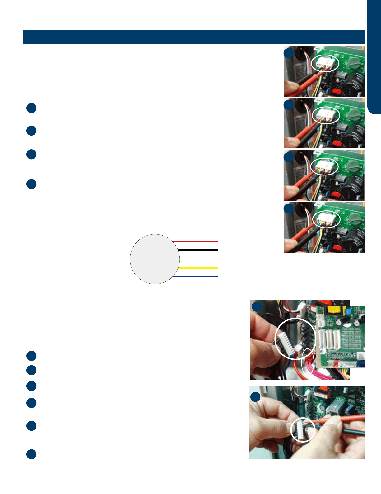
Outdoor Fan Motor
Check that the wiring and plug connections are in good condition.
Check the following voltages at connector CN11 on the outdoor unit PCB if the outdoor
unit fan motor does not run, or the Service Monitor Board indicates an error code of 09. Set
the meter to read DC volts with a minimum voltage range of 350 volts. All voltage values are
approximate. Initiate forced cooling.
DC voltage between the Red and Black wires on the CN11 plug should read 310 ~ 334
VDC. This is the main voltage for powering the fan motor.
DC voltage between the White and Black wires on the CN11 plug should read 15VDC.
This is the voltage for powering the electronic circuit of the fan motor.
DC voltage between the Yellow and Black wires on the CN11 plug should read 4VDC.
The voltage will read 0VDC when the fan is not being called to operate. This is the control
voltage for regulating the speed of the fan motor.
DC voltage between the Blue and Black wires on the CN11 plug should read 8VDC. The
voltage will read 14VDC when the fan is not being called to operate.
(This is the feedback voltage to the PCB for determining the speed of the fan motor)
The feedback circuit is not functioning if the outdoor fan initially runs, increases speed then
stops, and the Service Monitor Board indicates an error code of 09. Check that the wiring and
plug connections are in good condition.
Outdoor Fan 310VDC
Pins 1 - 3
Outdoor Fan 15VDC
Pins 3 - 4
Outdoor Fan Control
Pins 3 - 5
Outdoor Fan Feedback
Pins 3 - 6
Temperature Sensor
The temperature sensors are negative coecient thermistors in which resistance
decreases as temperature rises. The PCB will generate an appropriate error code
should the sensors fail.
To check the calibration of the sensors:
Shut o power to the outdoor unit.
Disconnect the sensor at the circuit board plug.
Measure the temperature of the air surrounding the sensor.
Measure the electrical resistance of the sensor using needle probes. Do not
force standard probes into the sensor plug.
Compare the measured resistance of the sensor against the resistance/
temperature specications (refer to Reference Information section for
sensor tables).
Replace the sensor if the sensor resistance is outside of the specication
tolerances shown on the resistance/temperature table.
1
1
1
2
3
4
5
6
2
3
4
2
3
4
2
4
DC Motor
+310 VDC
DC Ground
+15 VDC
Signal
Feedback
Red
Black
White
Yellow
Blue
PCB design may vary by model number
PCB design may vary by model number
Component Testing
ERROR CODES & TROUBLESHOOTING
PAGE 20
ENGLISH
Check to see if the Electronic expansion valve (EEV) connector is correctly and rmly inserted in the PCB.
Cycle the power o, then back on
Check to see whether the EEV produces a repositioning sound. This sound will start after approx 2 min. Disconnect
the connector and check the resistance (refer to resistance tables on following page) if the EEV doesn’t make the
repositioning sound.
The PCB may be at fault if the resistance is OK.
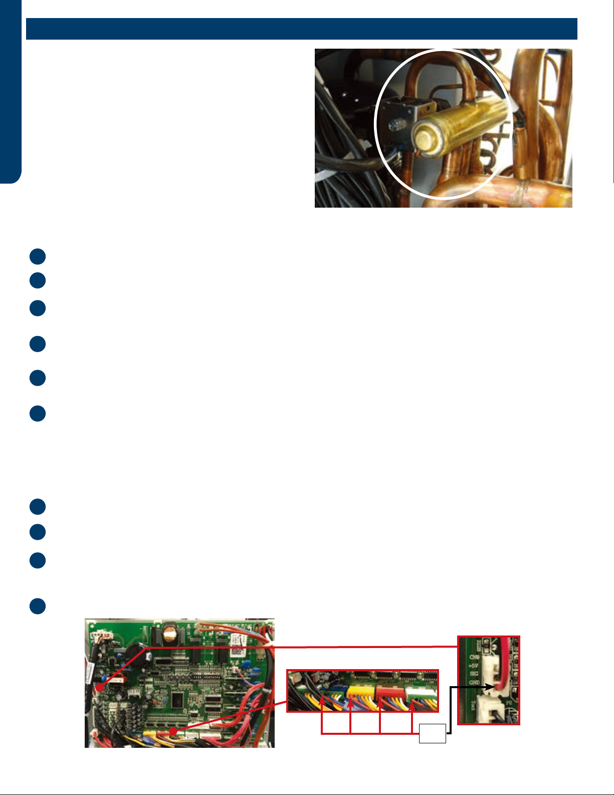
4-Way Valve
The 4-way valve will control the direction of hot gas discharge via
an internal slide assembly. The valve has a line voltage solenoid
that is energized in heat mode. The solenoid will direct the internal
slide to send the hot gas to the indoor coil. During cooling mode
de-energized operation, the internal slide will direct compressor
hot gas to the outdoor coil.
4-way valves may have a failure of the electrical solenoid that
prevents the valve from shifting, or they may become stuck due to
debris lodging inside the valve body. If the valve fails to direct the
hot gas in the proper direction, temperature sensors within the
outdoor unit will detect the problem and generate an error code.
Perform the following if the valve fails to shift the hot gas to the proper coil, or it only partially shifts:
Check for correct refrigerant charge, and that all other operating parameters have been met.
The solenoid will shift after a short time delay in the heating mode. Check for line voltage to the solenoid coil.
Shut the system down and unplug the 4-way valve from the PCB plug if the valve has voltage but fails to shift the hot gas
to the indoor coil.
Use an ohmmeter to check continuity through the solenoid coil. If the coil resistance does not match the chart in this
manual, or if a winding shows open or shorted, the solenoid coil must be replaced.
Use a magnet along the valve body to determine the location of the piston if the coil resistance is within the tolerance. It is
stuck and the valve must be replaced if one end of the piston is against the end of the valve body.
Partial shifting of the valve can be detected by measuring the temperature of the suction gas where it enters the
reversing valve and then comparing that temperature to the temperature of the suction gas exiting the 4-way valve.
There should be no more than 3F dierence. Excessive temperature rise through the suction gas path is an indication of
a stuck piston. The valve will require replacement if the piston will not become free by switching from heating to cooling
several times, a slight tapping on the valve body, or by using a powerful magnet.
1
1
2
2
3
3
4
4
5
6
12VDC
EEV Terminals
Electronic Expansion Valve (EEV)
PCB design may vary by model number
Component Testing
ERROR CODES & TROUBLESHOOTING PAGE 21
ENGLISH
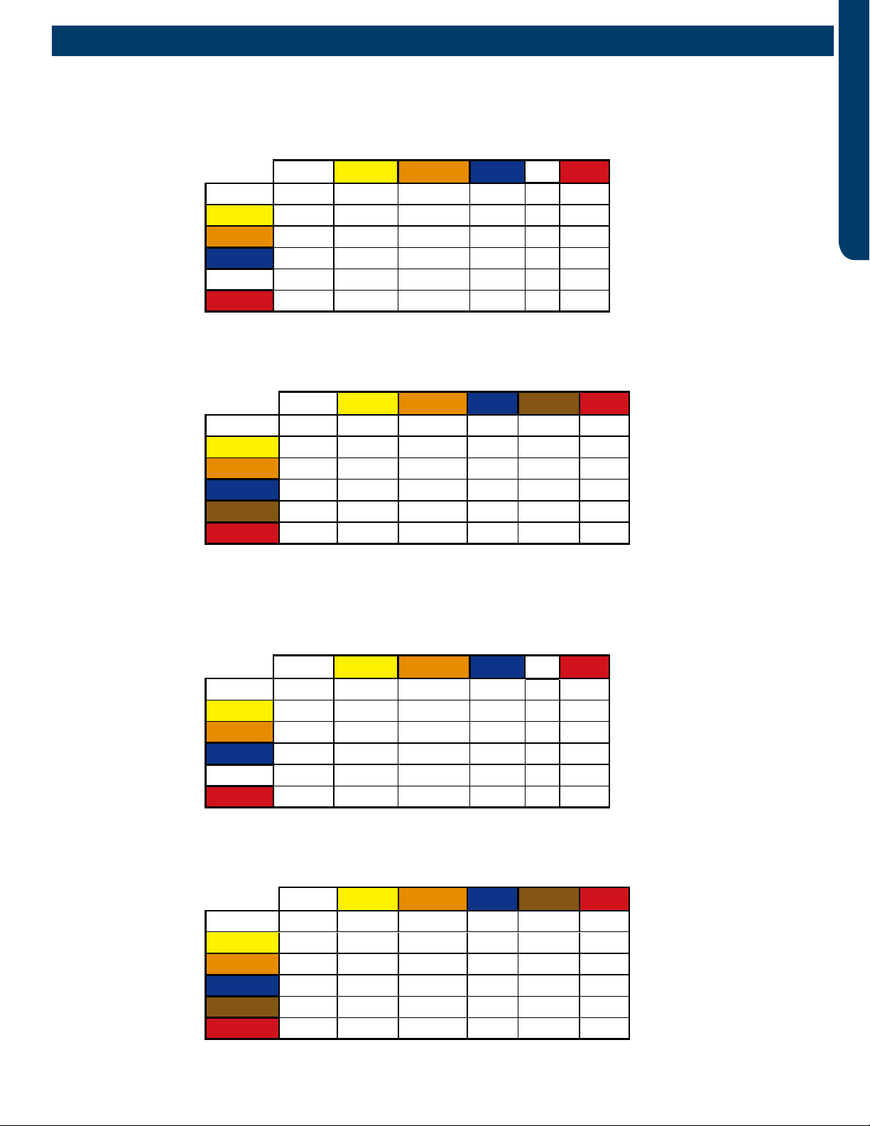
EEV (6-pin, 6 wire)
White Yellow Orange Blue Brown Red
White - OL 92 Ω OL 46 Ω OL
Yellow - - OL 92 Ω OL 46 Ω
Orange - - - OL 46 Ω OL
Blue - - - - OL 46 Ω
Brown - - - - - OL
Red - - - - - -
EEV (6-pin, 6 wire)
White Yellow Orange Blue Brown Red
White - OL 46 Ω OL 46 Ω OL
Yellow - - OL 46 Ω OL 46 Ω
Orange - - - OL 46 Ω OL
Blue - - - - OL 46 Ω
Brown - - - - - OL
Red - - - - - -
EEV (6-pin, 5 wire)
White Yellow Orange Blue XRed
White -92 Ω 92 Ω 92 Ω -46 Ω
Yellow - - 92 Ω 92 Ω -46 Ω
Orange - - - 92 Ω -46 Ω
Blue - - - - - 46 Ω
X - - - - - -
Red - - - - - -
EEV (6-pin, 5 wire)
White Yellow Orange Blue XRed
White -46 Ω 46 Ω 46 Ω -46 Ω
Yellow - - 46 Ω 46 Ω -46 Ω
Orange - - - 46 Ω -46 Ω
Blue - - - - - 46 Ω
X - - - - - -
Red - - - - - -
Component Testing
2U18MS2HDA / ASH218JCDDA
3U24MS2HDA / ASH324JCDDA
4U36MS2HDA / ASH436JCDDA
ERROR CODES & TROUBLESHOOTING
PAGE 22
ENGLISH
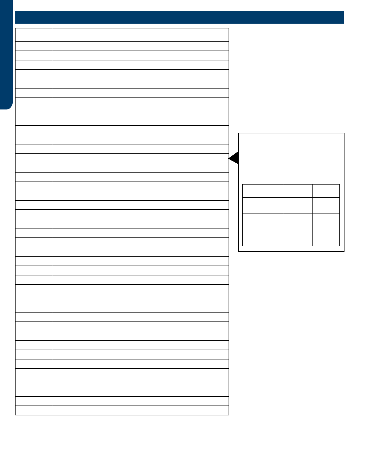
Error Code Diagnosis
1 Outdoor PCB EEPROM fault
2IPM fault
4Communication failure between IPM and PCB
5Compressor overload protection
6 Unreliable power input
8 Compressor discharge temperature too high
9Outdoor fan motor fault
10 Defrost sensor fault
11 Compressor suction temperature sensor fault
12 Outdoor ambient temperature sensor fault
13 Compressor discharge temperature sensor fault
15 Communication fault between indoor and outdoor unit
16 Lack of refrigerant
17 4-way valve switching failure
18 Compressor out of synchronism
20 Indoor thermal overload
21 Indoor coil frosted
23 IPM temperature too high
24 Compressor start failure
25 IPM current too high
26 PCB reset
27 IPM current detect circuit malfunction
28 Indoor unit A liquid pipe temperature sensor malfunction
29 Indoor unit B liquid pipe temperature sensor malfunction
30 Indoor unit C liquid pipe temperature sensor malfunction
31 Indoor unit D liquid pipe temperature sensor malfunction
32 Indoor unit A gas pipe temperature sensor malfunction
33 Indoor unit B gas pipe temperature sensor malfunction
34 Indoor unit C gas pipe temperature sensor malfunction
35 Indoor unit D gas pipe temperature sensor malfunction
36 Indoor unit E gas pipe temperature sensor malfunction
38 IPM temperature sensor fault/momentary power failure detected
39 Condensing temperature sensor malfunction
40 Indoor unit E liquid pipe temperature sensor malfunction
41 ‘Toci’ temperature sensor malfunction
42 High pressure switch open
43 Low pressure switch open
44 High pressure detected in system
45 Low pressure detected in system
Lo Ambient sensor low temperature detection
Precautions For Adding Refrigerant
1. This system must use refrigerant R410A.
2. Add refrigerant 0.2 oz/ft when the total
piping length exceeds the total pipe
length of factory charge, but make sure
that the total liquid piping length is less
than the max value.
Outdoor Unit Std. Value Max Value
2U18MS2HDA
ASH218JCDDA 50 ft. 98 ft.
3U24MS2HDA
ASH324JCDDA 75 ft. 197 ft.
4U36MS2HDA
ASH436JCDDA 131 ft. 230 ft.
Notes:
1. No addressing is necessary. All indoor
wiring connections must match the
outdoor connections, or a communication
failure will result.
2. Set SW5-8 to ON for Quiet Operation if
desired. Maximum capacity may be slightly
reduced.
3. Do not change any switch settings unless
directed to do so.
* PCB: Printed Circuit Board
* IPM: Inverter Power Module
* EEV: Electronic Expansion Valve
Error Codes
ERROR CODES & TROUBLESHOOTING PAGE 23
ENGLISH
Error Code 10
This code indicates an electrical failure of the sensor that is
used to sense the temperature of the outdoor coil during
defrost. This sensor is connected to the PCB via a connection
at Plug CN-14.
Error Code 11
This code indicates an electrical failure of the sensor that is
used to sense the temperature of the suction gas that enters
the compressor. The sensor is connected to the PCB via two
wires at Plug CN-14.
Error Code 12
This code indicates an electrical failure of the sensor that is
used to sense the temperature of the outdoor air. The sensor
is connected to the PCB via two wires at Plug CN-14.
Error Code 13
This code indicates an electrical failure of the sensor that is
used to sense the temperature of the compressor hot gas
discharge line. The sensor is connected to the PCB via two
wires at Plug CN-14.
Temperature Sensor Error Codes
The easiest problems to solve will involve codes that are related to potential failure of temperature sensors. Common problems
may include loose connections, open or shorted, and out of calibration. Checking the condition of the sensors requires a
temperature probe and an ohmmeter.
The Reference Section of this manual contains temperature resistance tables that can be used to check the calibration of the
sensors. The measured resistance must be within the tolerances located in the tables.
There are 16 potential Error Codes that can be generated by the PCB to indicate a failure of an outdoor unit temperature sensor.
Error codes are displayed on the service monitor board, the PCB LED-1 and the indoor display panel.
Error Code 28-36
These codes indicate a failure of either a Liquid or Gas
Temperature Sensor that is part of either the A, B, C, or
D indoor unit EEV circuit. Refer to the outdoor unit Error
Code Decal for specic identication of the malfunctioning
temperature sensor. These sensors connect to the PCB at
connection plugs near the center of the circuit board. (Note
that if the sensor has failed, and there is an unused port on
the unit available, the sensor from the unused port can be
used to temporarily x the problem.)
Error Code 38
This code indicates a potential failure of the IPM temperature
sensor. This sensor connects to the IPM via Plug CN-8. This
sensor is mounted near the heat sink.
Error Code 39
This code indicates an electrical failure of the sensor that is
used to sense the condensing temperature of the outdoor
coil. The sensor is connected to the PCB via two wires at Plug
CN-14.
Error Code 41
This code indicates an electrical failure of the 'Toci' sensor,
which ensures there is no drop in hot gas temperature
through the 4-way valve. The sensor is connected to the PCB
via two wires at Plug CN-7.
Outdoor Unit Error Codes
ERROR CODES & TROUBLESHOOTING
PAGE 24
ENGLISH
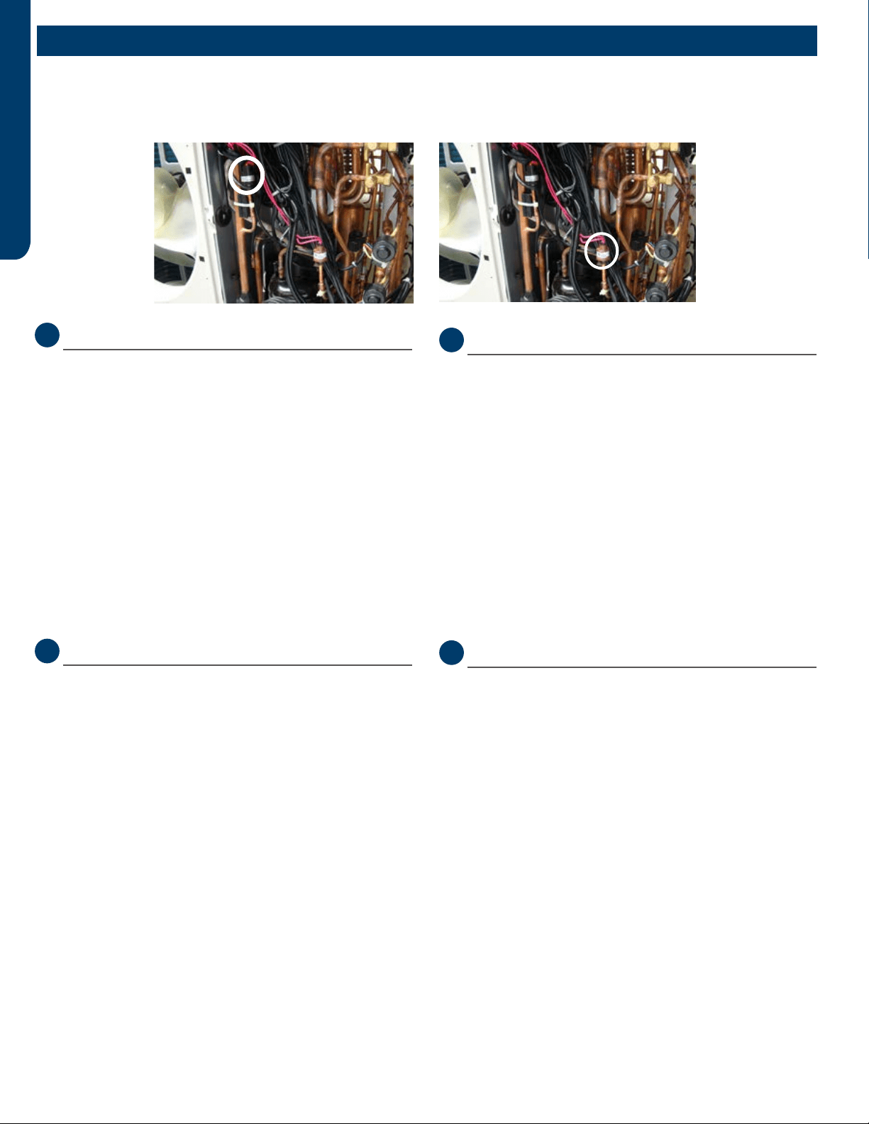
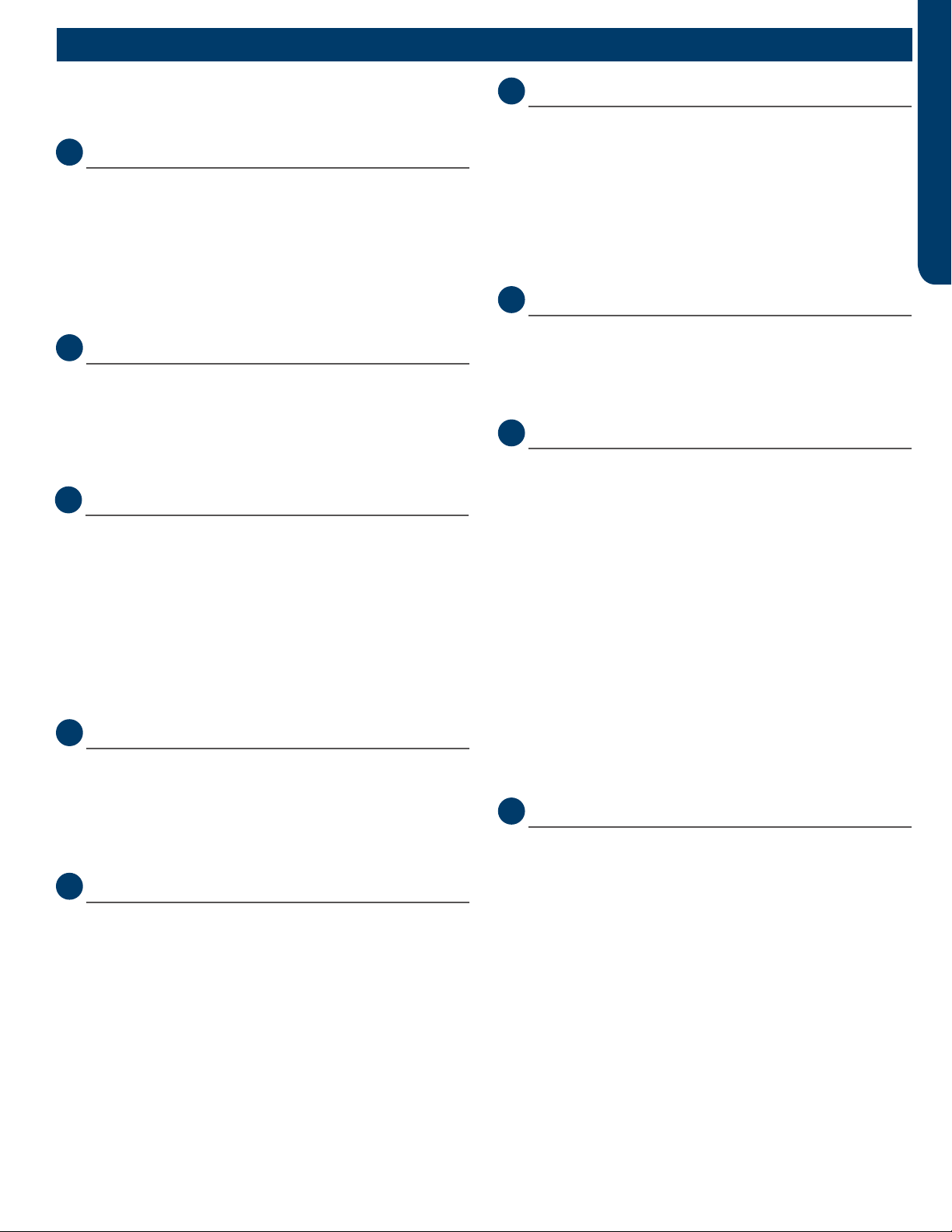
Error Code 42 & 43
The low pressure switch will generate an Error Code 43 if
open. An open high pressure switch will show an Error Code
42.
Testing Procedure
Check the continuity of the switch to ensure it is not open or
shorted If the system generates either of these two codes.
High or low pressures are usually related to dirt in the coils,
dirt in the air lter, or incorrect refrigerant charge.
There are no pressure ports that can be accessed to measure
low pressure in heat mode nor high pressure in cool mode. If
the system trips on one of these errors, it will be necessary to
remove the refrigerant and re-charge to conrm low or high
charge is not causing the problem.
Error Code 44
The system is operating at excessive refrigerant pressure.
It is likely that the charge is too high if the system is a new
installation. Note the weigh-in method is the ONLY way to
charge this system.
Typical Causes of High Pressure in Cooling Mode:
• Overcharge
• Dirty outdoor coil
• Restriction
Typical Causes of High Pressure in Heating Mode:
• Overcharge
• Undersized refrigerant lines or excessive length
• Restriction
Note: Replace the defective pressure switch if the refrigerant
pressures are correct, yet the system does not close the error
reporting pressure switch.
LowLow
PressurePressure
SwitchSwitch
High Pres-High Pres-
suresure
SwitchSwitch
Error Code 45
This code is indicating that system pressure is too low.
Typical Causes of Low Pressure in Cooling Mode:
• Lack of charge
• Low Heat on Indoor coil
• Restrictions, air ow, or dirt
• Low indoor load
Typical Causes of Low Pressure in Heating Mode:
• Cold outdoor air
• Lack of charge
• Restriction
Pressure-Related Error Codes
To protect the compressor, the PCB has a low pressure switch connection at CN13, and a high pressure switch connection at
CN12.
Communication Error Code
Error Code 15
Data travels between the units on the terminal block
connections 3/C and 1. A correct connection for each unit is
indicated by a solid green LED on the Service Monitor Board.
If an LED is ashing or not on, make sure the 14/4 stranded
copper communication cable connections are tight and
on the correct terminals. Additionally, ensure there are no
splices in the 3/C wire, and that the PCB connections at CN21
are in good order. An incomplete or inadequate ground can
easily be an issue.
Outdoor Unit Error Codes
ERROR CODES & TROUBLESHOOTING PAGE 25
ENGLISH
Error Codes Caused by Abnormal Refrigerant Circuit
Conditions
Error Code 8
This code indicates the temperature of the compressor hot
gas is too high. This error occurs after the PCB has attempted
to correct high temperature by reducing the compressor
speed, adjusting the fan speed, or opening the EEV. Causes
of this type of condition are typically a lack of refrigerant in
the system, excessive heat in the conditioned space, or a
restriction in the refrigeration circuit.
Error Code 16
This error code indicates the system may lack refrigerant.
Recover and check the system charge.
Outdoor Error Code Related to Indoor Unit
Error Code 21
This code indicates the indoor coil has frosted. This condition
can be due to a lack of heat in the conditioned space,
operating the indoor unit at excessively cold air temperature,
a blockage of air ow to the indoor unit, or an issue with the
indoor fan motor. This condition will cause the system to
enter an anti-freezing cycle.
Error Code Related to the PCB
Error Code 1
The EEPROM of the PCB cannot read or write data. Replace
the PCB.
Error Codes Related to the IPM
Error Code 2
The IPM has either failed or has detected excessive current.
Before replacing the IPM, check these potential causes of
high current:
• Overcharge
• Dirty outdoor coil
• Hot conditioned space
• High temperature or excessive load
• Refrigeration circuit restriction
• Seized compressor
• Faulty wiring or wiring connections
Error Code 4
This code indicates the IPM is not communicating with the
PCB. Check the wiring and the connections CN9 on the
PCB and CN15 on the IPM. If the connections are good, yet
the boards do not communicate and the code will not clear,
check for correct voltage at the IPM CN15 connection. If the
communication voltage is correct and the high voltage input
is present, replace the IPM. If the communication voltage is
not correct, replace the PCB.
Error Code 5
The IPM is protecting the compressor from overload, which
can be caused by low building power supply, restrictions, a
non-condensible in the system, a plugged coil, an excessive
load, or a refrigerant overcharge.
Error Code 6
This code indicates the operating voltage of the system is
either too high or too low. Check line voltage for proper limits.
The line voltage supplied to the outdoor unit should be no
lower than 187VAC when the compressor starts. The running
voltage should be no lower than 197VAC. The incoming line
voltage to the outdoor unit should never be higher than
253VAC. Check the supply voltage circuit from the building
for correct wire size and good connections if improper
voltage is present. Contact the power company to have
the service corrected if the voltage is still outside operating
limits.
Check the output voltage of the Power Filter if the line
voltage from the power company is correct. This voltage
connects to the IPM at terminals ACL and ACN.
Replace the PFB if the voltage is not within specications
shown above.
Error Code 18
There is a loss of synchronization among the U, V, and W
compressor windings during frequency changes as they slow
down or speed up the compressor.
Possible causes include:
• Unstable power supply
• Internal compressor fault
• IPM fault
• Compressor terminal wiring incorrect
• Poor wiring condition
• Loose compressor wiring connection
Outdoor Unit Error Codes
ERROR CODES & TROUBLESHOOTING
PAGE 26
ENGLISH
Error Code 23
This code indicates an IPM thermal overload. This error
was generated by a temperature sensor located in the IPM
heat sink. Causes of overheating are typically overcharge
of refrigerant, excessively plugged coil, sensor open or
shorted, or a non-condensable in system.
Error Code 26
Module reset indicates possible PCB power anomalies. This
usually occurs when low line voltage conditions are present.
Error Code 27
The IPM has detected that the compressor current is too
high.
Possible Causes:
• Overcharge
• Dirty outdoor coil
• Hot conditioned space temperature or high load
• Refrigeration circuit restriction
• Seized compressor
• Defective IPM
Error Codes Related to Compressor, Outdoor Fan &
4-Way Valve
Error Code 9
This code indicates the outdoor fan motor is not running. The
fault is detected very quickly by the PCB. The system will shut
o and display this error code. If this error occurs, refer to the
outdoor fan motor test procedure.
Error Code 17
This error code indicates that the 4-way valve is not directing
hot gas to the proper coil. Refer to the 4-way valve testing
procedure.
Error Code 24
This error code indicates the compressor failed to start when
a call for operation occurred. Refer to the compressor testing
procedure.
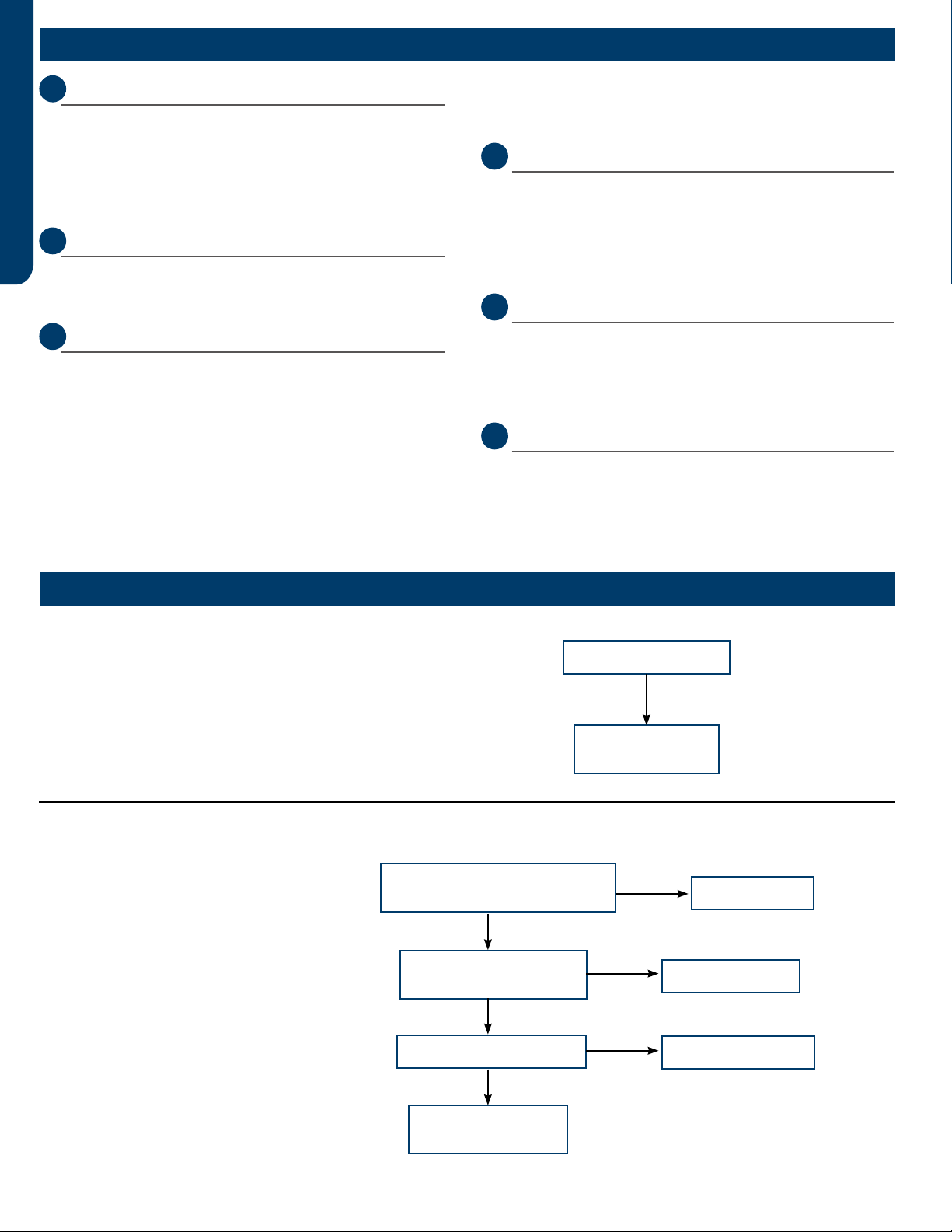
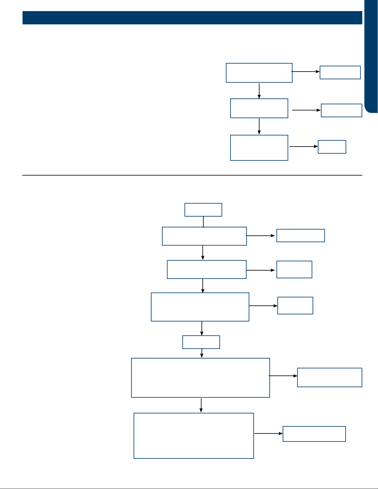
Code disappears after
power off/on again
Check outdoor
PCB. If faulty,
replace it.
No
[1] Outdoor EEPROM malfunction
EEPROM communication error; EEPROM data check
error (model ID, checksum, etc.); EEPROM data logic
error (wider data range, wrong order, etc.)
Possible causes:
• EEPROM is bad
• Loose EEPROM wiring
Correct the
wiring
Is electric box wiring correct,
and is compressor wiring firmly
connected?
Is compressor normal
(compressor coil resistor,
insulation)?
Is power module normal?
Replace
compressor
Replace power
module
Yes
Yes
Yes
No
No
No
Solve or correct any
failures according to
relative information
[2] Outdoor IPM over current or short circuit
3U24MS2HDA
Input over current detected by PIM’s hardware.
Possible causes:
• The IPM is bad
• Loose compressor wire
• The compressor is bad
Troubleshooting
Outdoor Unit Error Codes
ERROR CODES & TROUBLESHOOTING PAGE 27
ENGLISH
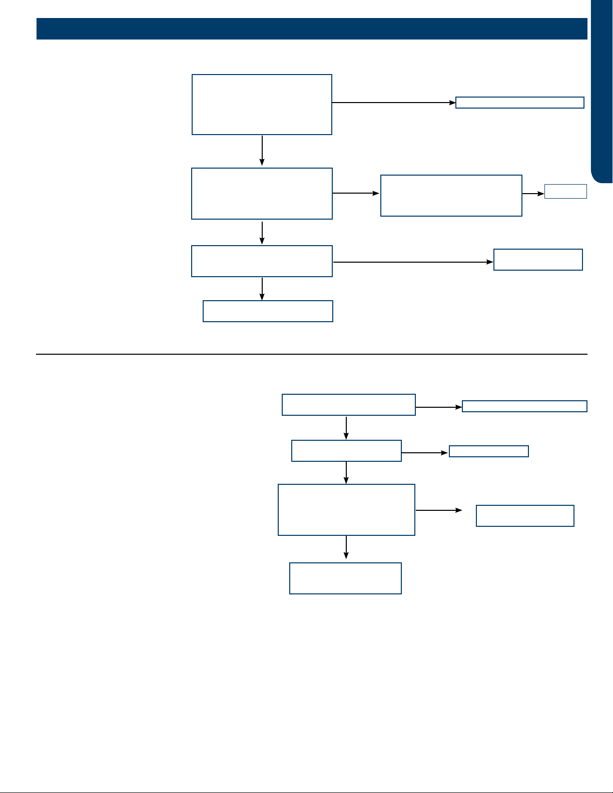
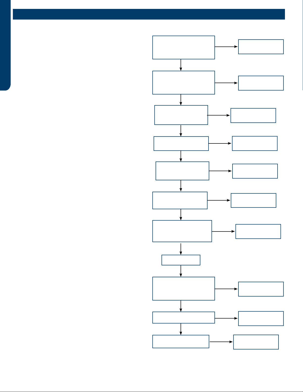
Adjust communication wire
Is the compressor drive module
input power normal (Test the
AC power supply voltage of the
module’s power input ACL-ACN:
normal value should between 196-
253VAC)?
Check the AC voltage between
the two terminals of power filter
board board P7& the terminal 3
of relay RL1 (208-230VAC)
Yes
Normal
No
Is the AC power supply wire
between compressor drive
module and filter
board firmly connected?
Fix wiring
Abnormal
Check if the output of main
control board CN6,CN34 are
both DC 12V
No Main control board
is bad, replace.
No
The filter board is broken,
replace the filter board
No
[4] Communication abnormal between PCB and IPM
Control board can not
communicate with the
compressor driver module for
over 4 minutes
Possible causes:
• The communication wire is bad
• The PCB is bad
• The power module is bad
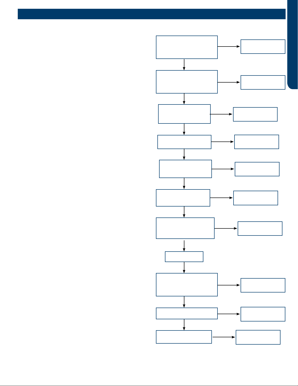
Correct power supply
Is power supply voltage
normal?
Is electric box wiring
correct?
Is power module voltage
between terminal P&N more
than 390V or less than 160V
during operation?
Correct the wiring
Replace power
module
Yes
Yes
No
No
Check rectifier, rector,
electrolytic capacitor on
inverter main circuit
No
Yes
[6] DC voltage or AC voltage high
Driver module AC power supply voltage over 280VAC,
or driver module DC-BUS voltage over 390VDC.
Possible causes:
• The power supply is abnormal
• Incorrect wiring
• Power module is bad
Troubleshooting

ERROR CODES & TROUBLESHOOTING
PAGE 28
ENGLISH
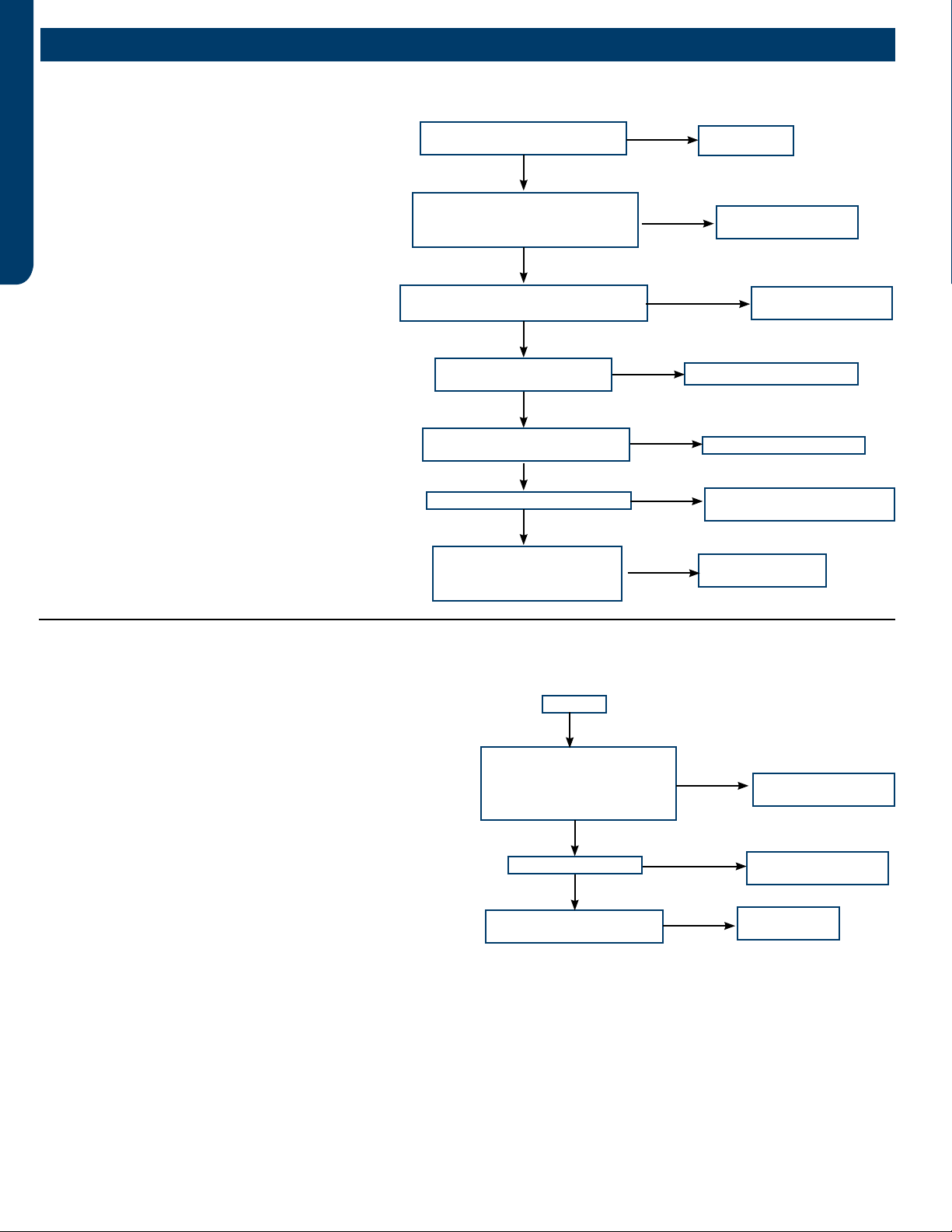
[8] Discharge temperature too high protection
Reconnect
Is sensor wiring firmly in place?
Is sensor resistance
within range?
Is the system is clogged?
Is the PMV coil wiring ok?
Is stop valve is open?
Replace pressure
switch
Check the piping system
Charge refrigerant
Check the piping system
Reconnect
Yes
No
Yes
Yes
No
Yes
No
No
Yes
No
No
Is the ambient temperature too
high?
Replace connecting
board
Yes
No
Is the system low on
refrigerant?
3U24MS2HDA
Compressor discharge temperature over 115°C. Error
clears within 3 minutes if temperature lowers below
115°C. Error status lock if it occurs 3 times in 1 hour.
Possible causes:
• The sensor is bad or xed bad
• The system is clogged
• The system lack of refrigerant
• The valve opening is wrong
Replace wire and test again
Are the fan motor wires
conductive?
Is the motor running?
Power off and rotate the
fan motor by hand. Does
it turn freely?
Is the terminial voltage
correct?
Replace
PCB
Replace fan
motor
Replace
PCB
Yes
Yes
Yes
Yes
No
No
No
No
Replace fan motor
[9] DC fan motor fault
DC fan motor damaged, not connected, or related
circuit broken. Error status conrms and locks if occurs
3 times within 30 minutes.
Possible causes:
• Loose motor wiring
• The motor is bad
• The PCB is bad
Troubleshooting
ERROR CODES & TROUBLESHOOTING PAGE 29
ENGLISH
Replace
sensor
Is the sensor wiring
firmly and correctly in
place?
Is the sensor
resistance within
range?
Is the temperature
loop acquired by
the computer board
normal?
Replace
sensor
Replace
it.
No
No
Yes
Yes
Yes
[10] Outdoor defrosting temperature sensor Te abnormal
[11] Suction temperature sensor Ts abnormal
[12] Outdoor ambient temperature sensor Ta abnormal
[13] Discharging temperature sensor Td abnormal
Sensor temperature has been detected below or higher than expected,
or has been detected as a shorted or open circuit
(for expected temperature, refer to part failure code)
Possible causes:
• Bad sensor connection
• The sensor is bad
• Sensor resistance drift
• The temperature acquired by PCB is not accurate
Replace wire
Is the communication wire
shorted?
Is the communication wire
CN21 disconnected? Reconnect
Reconnect
Yes
No
No
Yes
Is the wiring connection sequence
correct according to the wiring
diagram?
No
Measure the outdoor terminal block voltage
between communication 3 and N, and measure the
indoor terminal block between communication 3
and N to check. Is the communication wire ok?
Yes
Replace the
communication wire
Power off
Power on
No
Yes
Using a multimeter, measure the terminal
corresponding to the N-line voltage
of CN21 from the indoor unit with the
communication failure. Is the voltage
normal?
No PCB is bad, replace
PCB
[15] Communication abnormal between indoor unit and outdoor unit
Outdoor unit control board cannot communicate
with the indoor unit control board for over 4
minutes.
Possible causes:
• Bad communication wiring
• The PCB is bad
Troubleshooting

ERROR CODES & TROUBLESHOOTING
PAGE 30
ENGLISH
[16] Lack of refrigerant or discharging pipe blocked
Discharge & suction temperature Td-Ts≥80°C 10 minutes
after compressor start. Error status locks if it occurs 3
times in 1 hour.
Possible causes:
• Wrong sensor connection
• Lack of refrigerant
• The senor is bad
• The 4-way valve is bad
• The electronic expansion valve is bad
• Out of the operating range
Correct wiring
Is the sensor wiring correct
and firmly connected?
Is the system leaking, or
lacking refrigerant?
Is the resistance of the
Td and the Tcm sensors
within range?
Repair leak and recharge
refrigerant
Replace the
sensor
Yes
No
Yes
No
Use the unit according to
the allowable operating
range of the unit.
Yes
Is there an Internal
leakage in the 4-way
valve?
No
Replace 4-way
valve
Yes
No
Adjust the valve opening
Yes
Is the electronic
expansion valve over
throttled?
[17] 4-way valve reversing failure
Indoor pipe & indoor ambient temperature Tm-Tai≥5°C
10 minutes after compressor started. Error status locks
if it occurs 3 times in 1 hour.
Possible causes:
• The 4-way valve is bad
• The PCB is bad
• The 4-way valve coil connection is bad
• The system pressure dierence is too small.
Reconnect
Is connection between the
4-way valve and PCB good?
Is the 4-way valve coil
wiring firmly in place and
characteristics correct?
Is the system meeting
4-way valve reversing
conditions
(Pd-Ps>0.6Mpa)?
Is there air noise after 4-way
valve reverses, and the temp.
of connection pipes on 4-way
valve normal?
Correct wiring or replace
Check if the
compressor is running
Replace
PCB
Replace 4-way
valve
Yes
Yes
Yes
No
Yes
No
No
Yes
No
Is 208/230VAC Measured on
PVB CN5 PCB after 4-way
valve reversing conditons are
met?
Troubleshooting

ERROR CODES & TROUBLESHOOTING PAGE 31
ENGLISH
Correct power supply
Is supply voltage normal?
Is wire connection
between power module
and compressor correct?
Is power module is normal?
Correct the wiring
according to diagram
Replace power
module
Yes
Yes
Yes
No
No
No
Is compressor normal
(compressor coil resistor,
insulation)?
Replace
compressor
Yes
No
Compressor load is too
high, find the reason
[18] Compressor motor desynchronizing
Motor desynchronizing occurred. Caused by overload,
load sharply uctuating, abnormal compressor current
sensor circuit, or one of the inverter gate drive signals is
missing.
Possible causes:
• The power supply is abnormal
• Incorrect compressor wiring
• The power module is bad
• The compressor is bad
• The system is overload
Correct power supply
Is supply voltage normal?
Is wiring between power
module and compressor
correct?
Is power module normal?
Correct the wiring according
to diagram
Replace power
module
Yes
Yes
No
No
Compressor load too
high, find the reason
Yes
Is compressor normal
(compressor coil resistor,
insulation)?
No
Replace
compressor
No
[24] Compressor startup failure
Compressor start failure has been detected by driver
module.
Possible causes:
• The power supply is abnormal
• Incorrect compressor wiring
• The power module is bad
• The compressor is bad
• System overload
Correct the wiring according
to diagram
Is electric box and compressor
wiring correct and firmly in place?
Is compressor normal
(compressor coil resistor,
insulation)?
Is power module is normal?
Replace
compressor
Replace power
module
Yes
Yes
Yes
No
No
No
[25] Input overcurrent of the drive module
Compressor drive module input current higher
than 32A (double fan model), or 27A (single fan).
Locks if it occurs 3 times in 1 hour.
Possible causes:
• Incorrect compressor wiring
• The power module is bad
• The compressor is bad
Solve or correct any
failures according to
relative information
Troubleshooting
ERROR CODES & TROUBLESHOOTING
PAGE 32
ENGLISH
Use multimeter to check
if the high pressure switch
terminal is short circuit
Use the multimeter to
check if the resistance of
Tc & Tm is ok
Check if the EEV coil is
fully seated
Power on
Check if service valve is
open
Short high pressure switch
terminal on the PCB to check
if the system reports failure
Check if the piping
system is clogged
Check if fan motor is ok
Check if the resistance of
Te and Tc is ok
Power off, check if the
pressure switch connection
is ok.
Check if the connection
pipe is bent
The pressure switch
is bad; replace it
Replace the sensor
Reconnect
Replace the
connection pipe
Reconnect the EEV
coil
Open the service
valve
The PCB is
broken,replace it.
Clean the piping
system
Replace the fan
motor
Replace sensor
Yes
Yes
Yes
Yes
Yes
Yes
No
No
Yes
No
No
No
No
No
No
Yes
Yes
No
No
[42] Open high pressure switch
High pressure switch: Switch circuit has been detected open
for 30 seconds (after 3 minute of compressor run time). Error
locks if it occurs 3 times in 1 hour.
Possible causes:
• Incorrect pressure switch wiring
• Abnormal system pressure
• System is clogged
• Incorrect refrigerant charge
• Bad valve
• Pressure switch is bad
• PCB is bad
Troubleshooting
ERROR CODES & TROUBLESHOOTING PAGE 33
ENGLISH
[43] Open low pressure switch
Low pressure switch: Switch has been detected
open for 60 seconds (after 3 minute of compressor
run time) or open for 30 seconds during standby.
Possible causes:
• Incorrect pressure switch wiring
• Abnormal system pressure
• System is clogged
• Incorrect refrigerant charge
• Bad valve
• Pressure switch is bad
• PCB is bad
Use multimeter to check
if the high pressure switch
terminal is short circuit
Use the multimeter to
check if the resistance of
Tc & Tm is ok
Check if the EEV coil is
fully seated
Power on
Check if service valve is
open
Short high pressure switch
terminal on the PCB to check
if the system reports failure
Check if the piping
system is clogged
Check if fan motor is ok
Check if the resistance of
Te and Tc is ok
Power off, check if the
pressure switch connection
is ok.
Check if the connection
pipe is bent
The pressure switch
is bad; replace it
Replace the sensor
Reconnect
Replace the
connection pipe
Reconnect the EEV
coil
Open the service
valve
The PCB is
broken,replace it.
Clean the piping
system
Replace the fan
motor
Replace sensor
Yes
Yes
Yes
Yes
Yes
Yes
No
No
Yes
No
No
No
No
No
No
Yes
Yes
No
No
Troubleshooting
ERROR CODES & TROUBLESHOOTING
PAGE 34
ENGLISH
Reconnect
Power off. Is pressure switch
wiring connection ok?
Use multimeter to check the high
pressure switch. Is the switch
short circuited?
Is the EEV coil wiring correct and
firmly in place?
Is the service valve is
open?
Use a multimeter to check
the resistance of Tc & Tm.
Are they withing range?
Is the piping system is
clogged?
Is the connection pipe is bent?
The pressure is bad,
replace it.
Open the service valve
Clean the piping system
Replace the connection
pipe
Replace the
sensor
Yes
Yes
No
Yes
Yes
No
No
No
No
No
Yes
No No
Reconnect the EEV
coil wiring
[44] High pressure detected in system
The minimum temperature value of indoor pipe Tm
and outdoor Ts is lower than -45 °C during cooling
mode, or minimum temperature value of outdoor
Tc and outdoor Te is lower than -45 °C.
Possible causes:
• High pressure sensor detection value is incorrect
• Refrigerant overcharge
• Blocked liquid line piping
• The outdoor unit cannot be turned on normally
due to failure to open outdoor heat exchanger
electronic expansion valve when heating.
• The operation environment is beyond the allowed
range.
Power on
Short the low pressure
switch terminal on the PCB.
Does the system report a
failure?
Is the fan motor ok?
Is the resistance of Te and
Tc2 in range?
The PCB is bad,
replace it.
Replace
sensor
No
Yes
Yes
Yes
No
No Replace the fan
motor
[45] Low pressure detected in system
The minimum temperature value of indoor pipe Tm and
outdoor Ts is lower than -45 °C during cooling mode, or
minimum temperature value of outdoor Tc and outdoor Te is
lower than -45 °C.
Possible causes:
• Low pressure sensor detection value is incorrect
• Low refrigerant charge
• System air leakage
• Blocked low pressure or liquid line piping
• The outdoor unit cannot be turned on normally due
to failure to open outdoor heat exchanger electronic
expansion valve when heating.
• The operation environment is beyond the allowed range.
Troubleshooting
REFERENCE INFORMATION PAGE 35
ENGLISH
Reference Information
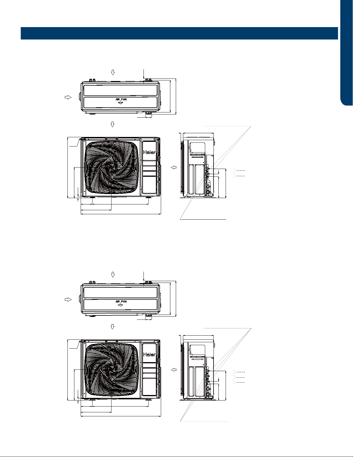
Dimensions
2U18MS2HDA
ASH218JCDDA
3U24MS2HDA
ASH324JCDDA
l
e
t
A
i
r
o
u
t
Handle
A
i
r
i
n
l
e
t
3U24MS2HDA
4U36MS2HDA
13 5/8 (346)
16 1/8 (410)
14 1/2 (368)
3/4 (20)
Vapor Connection
All Ports - 3/8 flare
Vapor Connection
All Ports - 3/8 flare
13 1/4 (337)
7 3/8 (187)
1 1/8
(30)
1 (26)
2 3/4 (70)
35 3/8 (900)
5 1/8 (130) 24 7/8 (632)
3/4 (19)
13 7/8 (353)
27 1/2 (700)
13 5/8 (345)
Ø
Ø
Liquid Connection
All Ports - 1/4 Flare
Liquid Connection
All Ports - 1/4 Flare
l
e
t
A
i
r
o
u
t
Handle
A
i
r
i
n
l
e
t
2U18MS2HDA
13 5/8 (346)
16 1/8 (410)
14 1/2 (368)
3/4 (20)
13 1/4 (337)
9 3/4 (247)
1 1/8
(30)
1 (26)
2 3/4 (70)
35 3/8 (900)
5 1/8 (130) 24 7/8 (632)
3/4 (19)
13 7/8 (353)
27 1/2 (700)
13 5/8 (345)
Ø
Ø
Indoor and outdoor
connect wiring hole
(5 @ 3/4 dia)
Air outlet
Air inlet
14 5/8 (370)
1 3/4 (45)
1 3/4 (45)
18 1/8 (460)
16 1/8 (410)
2 5/8 (68)
7 (178)23 3/8 (595)7 (178)
Handle
Handle
37 1/2 (951)
37 5/8 (956)
7/8 (22)
D
C
B
A
Handle
A unit connection
B unit connection
C unit connection
A unit connection
B unit connection
A unit connection
B unit connection
C unit connection
D unit connection
Vapor pipe
Ports A, B, C - 3/8 flare
Port D - 1/2 flare
Liquid pipe
All Ports - 1/4 flare
2 3/4 (70)
7/8 (23)
15 3/8 (390)
3 1/2 (90)
2 (52)
2 3/8 (60)
2 3/8 (60)
21 1/2 (545)
1 1/8 (30)
18 1/2 (470)
17 3/8 (440)
10 1/4 (260)
11 3/8 (290)
l
e
t
A
i
r
o
u
t
Handle
A
i
r
i
n
l
e
t
3U24MS2HDA
4U36MS2HDA
13 5/8 (346)
16 1/8 (410)
14 1/2 (368)
3/4 (20)
Vapor Connection
All Ports - 3/8 flare
Vapor Connection
All Ports - 3/8 flare
13 1/4 (337)
7 3/8 (187)
1 1/8
(30)
1 (26)
2 3/4 (70)
35 3/8 (900)
5 1/8 (130) 24 7/8 (632)
3/4 (19)
13 7/8 (353)
27 1/2 (700)
13 5/8 (345)
Ø
Ø
Liquid Connection
All Ports - 1/4 Flare
Liquid Connection
All Ports - 1/4 Flare
l
e
t
A
i
r
o
u
t
Handle
A
i
r
i
n
l
e
t
2U18MS2HDA
13 5/8 (346)
16 1/8 (410)
14 1/2 (368)
3/4 (20)
13 1/4 (337)
9 3/4 (247)
1 1/8
(30)
1 (26)
2 3/4 (70)
35 3/8 (900)
5 1/8 (130) 24 7/8 (632)
3/4 (19)
13 7/8 (353)
27 1/2 (700)
13 5/8 (345)
Ø
Ø
Indoor and outdoor
connect wiring hole
(5 @ 3/4 dia)
Air outlet
Air inlet
14 5/8 (370)
1 3/4 (45)
1 3/4 (45)
18 1/8 (460)
16 1/8 (410)
2 5/8 (68)
7 (178)23 3/8 (595)7 (178)
Handle
Handle
37 1/2 (951)
37 5/8 (956)
7/8 (22)
D
C
B
A
Handle
A unit connection
B unit connection
C unit connection
A unit connection
B unit connection
A unit connection
B unit connection
C unit connection
D unit connection
Vapor pipe
Ports A, B, C - 3/8 flare
Port D - 1/2 flare
Liquid pipe
All Ports - 1/4 flare
2 3/4 (70)
7/8 (23)
15 3/8 (390)
3 1/2 (90)
2 (52)
2 3/8 (60)
2 3/8 (60)
21 1/2 (545)
1 1/8 (30)
18 1/2 (470)
17 3/8 (440)
10 1/4 (260)
11 3/8 (290)
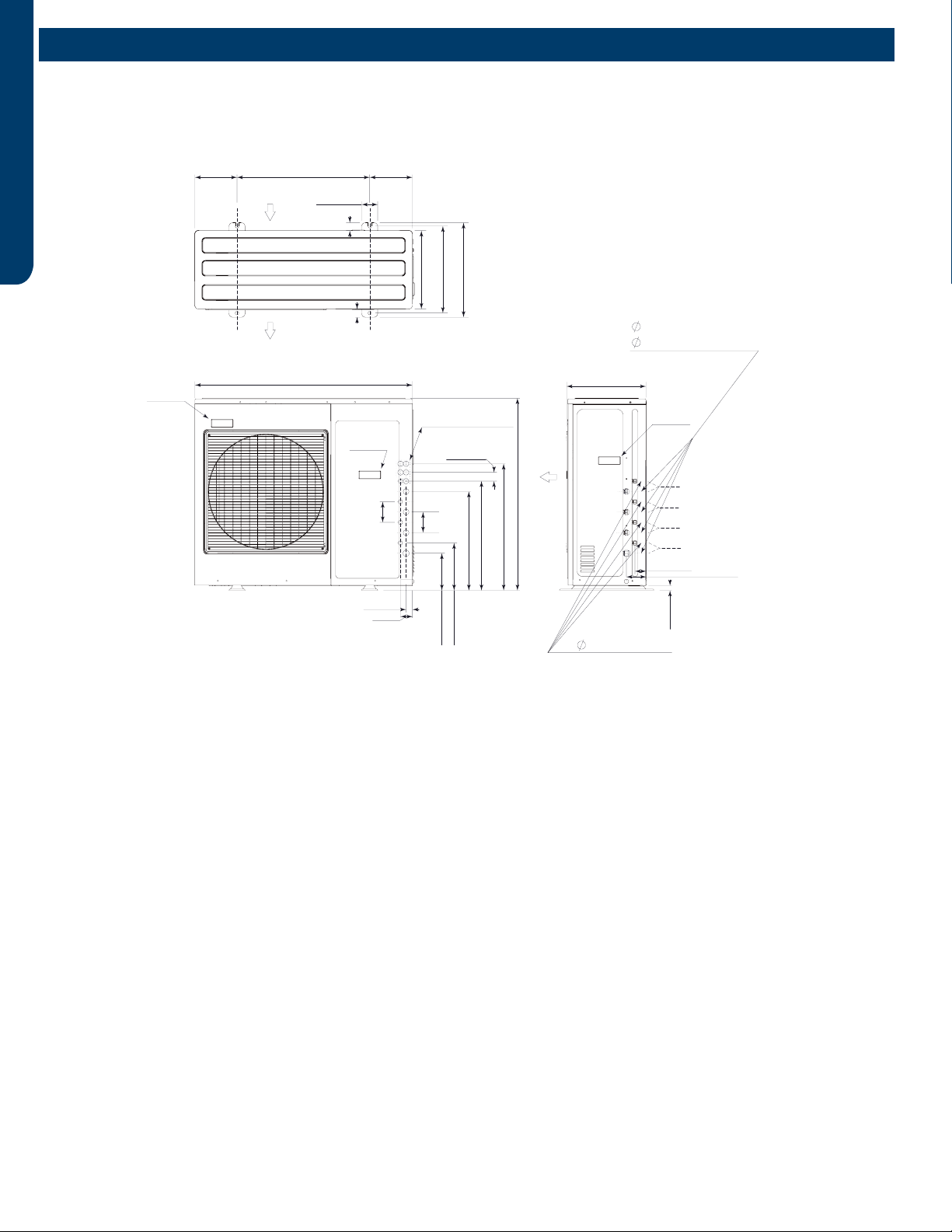
REFERENCE INFORMATION
PAGE 36
ENGLISH
Dimensions
4U36MS2HDA
ASH436JCDDA
l
e
t
A
i
r
o
u
t
Handle
A
i
r
i
n
l
e
t
3U24MS2HDA
4U36MS2HDA
13 5/8 (346)
16 1/8 (410)
14 1/2 (368)
3/4 (20)
Vapor Connection
All Ports - 3/8 flare
Vapor Connection
All Ports - 3/8 flare
13 1/4 (337)
7 3/8 (187)
1 1/8
(30)
1 (26)
2 3/4 (70)
35 3/8 (900)
5 1/8 (130) 24 7/8 (632)
3/4 (19)
13 7/8 (353)
27 1/2 (700)
13 5/8 (345)
Ø
Ø
Liquid Connection
All Ports - 1/4 Flare
Liquid Connection
All Ports - 1/4 Flare
l
e
t
A
i
r
o
u
t
Handle
A
i
r
i
n
l
e
t
2U18MS2HDA
13 5/8 (346)
16 1/8 (410)
14 1/2 (368)
3/4 (20)
13 1/4 (337)
9 3/4 (247)
1 1/8
(30)
1 (26)
2 3/4 (70)
35 3/8 (900)
5 1/8 (130) 24 7/8 (632)
3/4 (19)
13 7/8 (353)
27 1/2 (700)
13 5/8 (345)
Ø
Ø
Indoor and outdoor
connect wiring hole
(5 @ 3/4 dia)
Air outlet
Air inlet
14 5/8 (370)
1 3/4 (45)
1 3/4 (45)
18 1/8 (460)
16 1/8 (410)
2 5/8 (68)
7 (178)23 3/8 (595)7 (178)
Handle
Handle
37 1/2 (951)
37 5/8 (956)
7/8 (22)
D
C
B
A
Handle
A unit connection
B unit connection
C unit connection
A unit connection
B unit connection
A unit connection
B unit connection
C unit connection
D unit connection
Vapor pipe
Ports A, B, C - 3/8 flare
Port D - 1/2 flare
Liquid pipe
All Ports - 1/4 flare
2 3/4 (70)
7/8 (23)
15 3/8 (390)
3 1/2 (90)
2 (52)
2 3/8 (60)
2 3/8 (60)
21 1/2 (545)
1 1/8 (30)
18 1/2 (470)
17 3/8 (440)
10 1/4 (260)
11 3/8 (290)
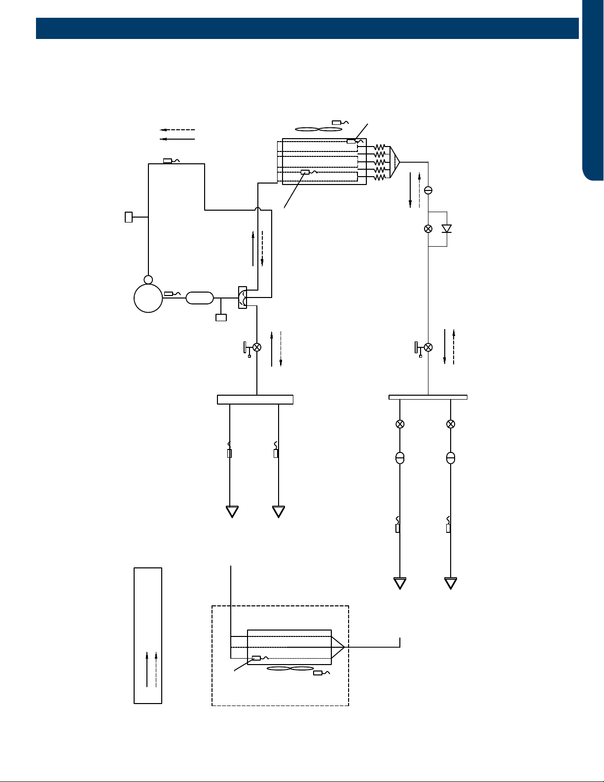
REFERENCE INFORMATION PAGE 37
ENGLISH
Comp-
ressor
Discharge temp.
sensor
High pressure
swtich
4-way valve
Suction temp.
sensor
Low pressure
switch
Gas stop valve
Outdoor
heat
exchanger
temp.
sensor
FAN-OUT
Outdoor
ambient
temperature
sensor
Defrost
sensor
Distributor
Strainer
EEV O
Check valve
Liquid stop valve
5/8
3/8
EEV A
Strainer
Unit A liquid pipe temp. sensor
Indoor unit A
EEV B
Strainer
Unit B liquid pipe temp. sensor
Indoor unit B
Unit A gas pipe temp. sensor
Unit B gas pipe temp. sensor
Indoor unit A
Indoor unit B
4-way valve coil:
OFF
ON
Refrigerant flow in cooling
Refrigerant flow in heating
FAN-IN
Indoor
ambient
temperature
sensor
Indoor
heat
exchanger
temp.
sensor
Muffler
Piping Diagrams
2U18MS2HDA
ASH218JCDDA
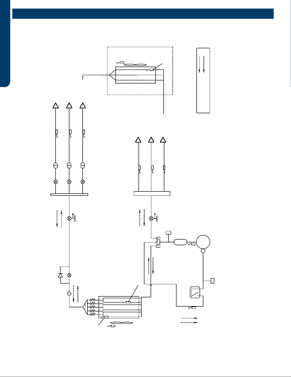
REFERENCE INFORMATION
PAGE 38
ENGLISH
3U24MS2HDA
ASH324JCDDA
Comp-
ressor
Discharge temp.
sensor
High pressure
swtich
4-way valve
Suction temp.
sensor
Low pressure
switch
Gas stop valve
Outdoor
heat
exchanger
temp.
sensor
FAN-OUT
Outdoor
ambient
temperature
sensor
Defrost
sensor
Distributor
Strainer
EEV O
Check valve
Liquid stop valve
5/8
3/8
EEV A
Strainer
Unit A liquid pipe temp. sensor
Indoor unit A
EEV B
Strainer
Unit B liquid pipe temp. sensor
Indoor unit B
EEV C
Strainer
Unit C liquid pipe temp. sensor
Indoor unit C
Unit A gas pipe temp. sensor
Unit B gas pipe temp. sensor
Unit C gas pipe temp. sensor
Indoor unit A
Indoor unit B
Indoor unit C
4-way valve coil:
OFF
ON
Refrigerant flow in cooling
Refrigerant flow in heating
FAN-IN
Indoor
ambient
temperature
sensor
Indoor
heat
exchanger
temp.
sensor
Gas-liquid
separator
Muffler
Piping Diagrams
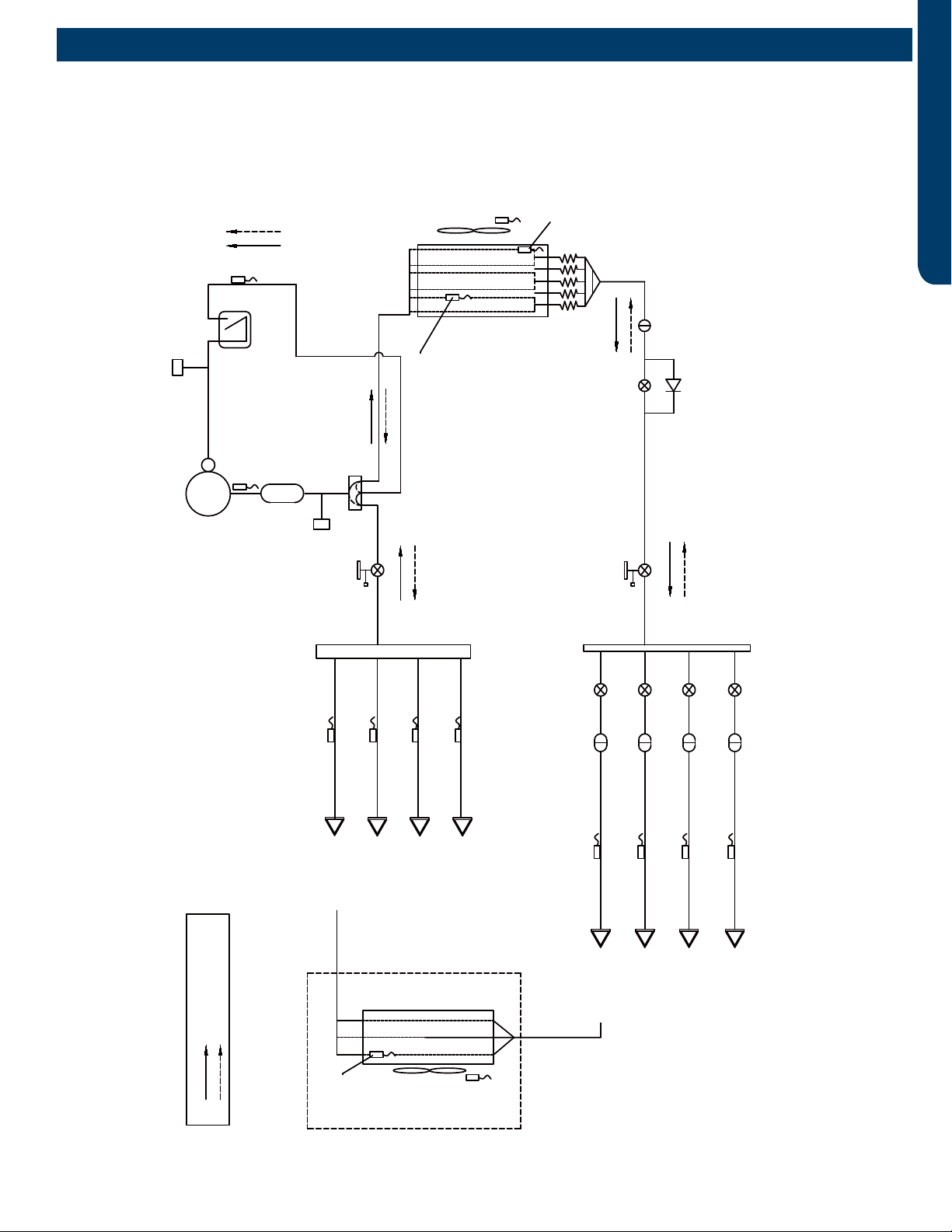
REFERENCE INFORMATION PAGE 39
ENGLISH
Piping Diagrams
4U36MS2HDA
ASH436JCDDA
Comp-
ressor
Discharge temp.
sensor
High pressure
swtich
4-way valve
Muffler
Gas-liquid
separator
.pmet noitcuS
rosnes
Low pressure
switch
Gas stop valve
Outdoor
heat
exchanger
temp.
sensor
FAN-OUT
Outdoor
ambient
temperature
sensor
Defrost
sensor
Distributor
Strainer
EEV O
Check valve
Liquid stop valve
5/8
3/8
EEV A
Strainer
Unit A liquid pipe temp. sensor
Indoor unit A
EEV B
Strainer
Unit B liquid pipe temp. sensor
Indoor unit B
EEV C
Strainer
Unit C liquid pipe temp. sensor
Indoor unit C
Indoor unit D
EEV D
Strainer
Unit D liquid pipe temp. sensor
Unit A gas pipe temp. sensor
Unit B gas pipe temp. sensor
Unit C gas pipe temp. sensor
Indoor unit A
Indoor unit B
Indoor unit C
Unit D gas pipe temp. sensor
Indoor unit D
4-way valve coil:
OFF
ON
Refrigerant flow in cooling
Refrigerant flow in heating
FAN-IN
Indoor
ambient
temperature
sensor
Indoor
heat
exchanger
temp.
sensor
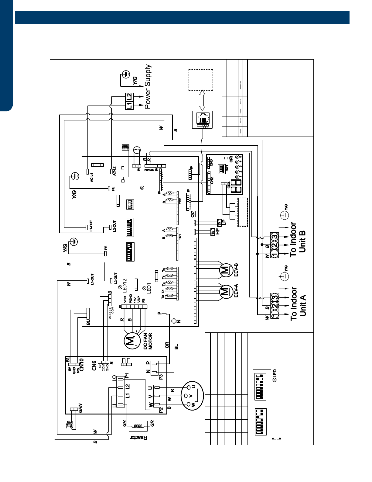
REFERENCE INFORMATION
PAGE 40
ENGLISH
ENGLISH
12345678
0150550339
NOTE : 1.Dashed parts are optional.
2.Please refer to service manual to getde tails of the DIPs
witches .3.Do not change the DIPs witches setting without
technical support.4.Other details a bout the service nformation
please please refer totechnical service mannual.
2U18MS2HDA
C1 C2
AB
central controller
RJ45
service
tool
12345678
EEV_RE EEV_A EEV_B EEV_C
Means switch at ON position
Means switch at OFF position
ON
ON
OR:orange,B:black ,BL:blue,BR:brown,GR:grey,GRN:green
Y/G:yellow/green,YL:yellow,R:red, W:white
COMPPRESSOR
SW1-1 SW1-2 SW1-3 SW1-4 Definition of display board SW1
OFF OFF OFF OFF Normal operation(Default)
OFF OFF OFF Manually forced heating
OFF OFF OFF
OFF
OFF OFF Rated operation(fixed speed)
OFF OFFOFF Time defrost valid
IDU&ODU wiring error check
ON
ON Manually forced cooling
ON
ON
ON ON ON ON
ON ON
Factory default setting of main control board
SW5 SW7
Module
power
CN22
12345678
12345678
ON ON
SW5 SW7
SW6
Tc:Condensing Temp.Sensor
Ts:Compressor Suction Temp.Sensor
Ta: Ambient Temp.Sensor
Td:Compressor Discharge Temp.Sensor
Te:Defrosting Temp.Sensor
Tc1(a/b/c/d/e):Condensing Temp.Sensor for
Indoor Units a/b/c/d/e(Gas Pipe)
Tc2(a/b/c/d/e):Condensing Temp.Sensor for
Indoor Unitsa/b/c/d/e(Liquid Pipe)
Toci:Condesing Temp.sendor for inlet pipe
Tfin:Module heat sink fin Tem.sensor
LP/HP:Low /high pressure switch
E.E.V:electro expansion valve
Centralized control
Address=1
Address=2
Address=16
Definition of main control board SW6
OFF OFF OFF OFF
SW6-1 SW6-2 SW6-3 SW6-4
ON OFF OFF OFF
ON ON ON ON
ON
ON
CN33
CN34 CN35
CN32
CN31 CN3
CN1
CN2
W
B
CON9
CON8
CN5
LED15
CRANKCASE
HEATER
4 WAY
VALVE
CN8
CN21
CN23
CN47
CN25
CN14 CN24
RYL
BL
CN26
CN27
CN15 CN16 CN17 CN18
CN12 CN13
CN11
CN9
MAIN CONTROL BOARD
COMPRSSOR
DRIVE
MODULE
GND
COM
5V
15V
GND
5V
DISPLAY BOARD
RW
RJ45 adapter
board
FUSE1
250VAC T25A
WB
W
B
CN8
CN17
R
BR
FUSE2
250VAC T3.15A
250VAC T3.15A
FUSE3
250VAC T5A
FUSE4
RYL GR BL
RR
Wiring Diagrams
2U18MS2HDA
ASH218JCDDA
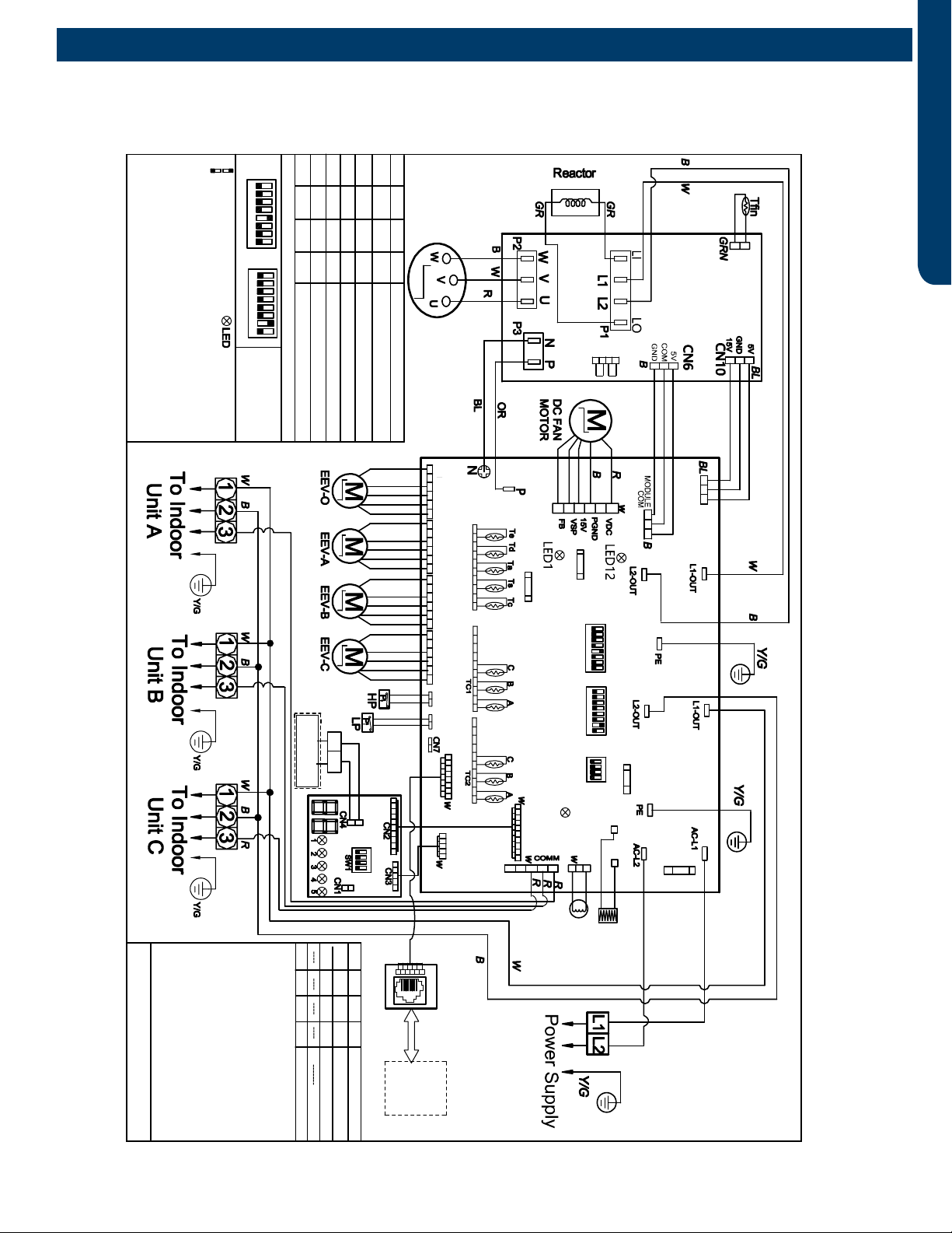
REFERENCE INFORMATION PAGE 41
ENGLISH
12345678
0150550334
NOTE : 1.Dashed parts are optional.
2.Please refer to service manual to getde tails of the DIPs
witches .3.Do not change the DIPs witches setting without
technical support.4.Other details a bout the service nformation
please please refer totechnical service mannual.
3U24MS2HDA
C1 C2
AB
central controller
RJ45
service
tool
12345678
EEV_RE EEV_A EEV_B EEV_C
Means switch at ON position
Means switch at OFF position
ON
ON
OR:orange,B:black ,BL:blue,BR:brown,GR:grey,GRN:green
Y/G:yellow/green,YL:yellow,R:red, W:white
COMPPRESSOR
SW1-1 SW1-2 SW1-3 SW1-4 Definition of display board SW1
OFF OFF OFF OFF Normal operation(Default)
OFF OFF OFF Manually forced heating
OFF OFF OFF
OFF
OFF OFF Rated operation(fixed speed)
OFF OFFOFF Time defrost valid
IDU&ODU wiring error check
ON
ON Manually forced cooling
ON
ON
ON ON ON ON
ON ON
Factory default setting of main control board
SW5 SW7
Module
power
CN22
12345678
12345678
ON ON
SW5 SW7
SW6
Tc:Condensing Temp.Sensor
Ts:Compressor Suction Temp.Sensor
Ta: Ambient Temp.Sensor
Td:Compressor Discharge Temp.Sensor
Te:Defrosting Temp.Sensor
Tc1(a/b/c/d/e):Condensing Temp.Sensor for
Indoor Units a/b/c/d/e(Gas Pipe)
Tc2(a/b/c/d/e):Condensing Temp.Sensor for
Indoor Unitsa/b/c/d/e(Liquid Pipe)
Toci:Condesing Temp.sendor for inlet pipe
Tfin:Module heat sink fin Tem.sensor
LP/HP:Low /high pressure switch
E.E.V:electro expansion valve
Centralized control
Address=1
Address=2
Address=16
Definition of main control board SW6
OFF OFF OFF OFF
SW6-1 SW6-2 SW6-3 SW6-4
ON OFF OFF OFF
ON ON ON ON
ON
ON
CN33
CN34 CN35
CN32
CN31 CN3
CN1
CN2
W
B
CON9
CON8
CN5
LED15
CRANKCASE
HEATER
4 WAY
VALVE
CN8
CN21
CN23
CN47
CN25
CN14 CN24
RYL
BL
CN26
CN27
CN15 CN16 CN17 CN18
CN12 CN13
CN11
CN9
MAIN CONTROL BOARD
COMPRSSOR
DRIVE
MODULE
GND
COM
5V
15V
GND
5V
DISPLAY BOARD
RW
RJ45 adapter
board
FUSE1
250VAC T25A
WB
W
B
CN8
CN17
R
BR
FUSE2
250VAC T3.15A
250VAC T3.15A
FUSE3
250VAC T5A
FUSE4
RYL GR BL
Wiring Diagrams
3U24MS2HDA
ASH324JCDDA
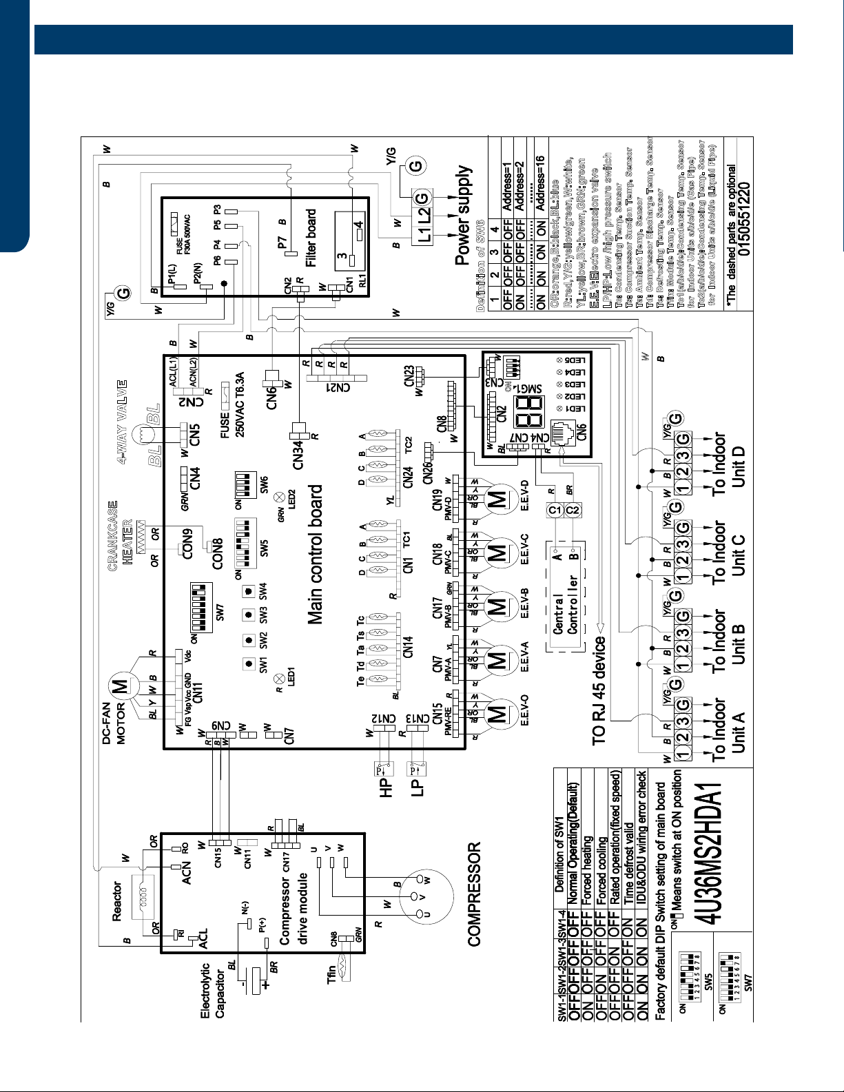
REFERENCE INFORMATION
PAGE 42
ENGLISH
Wiring Diagrams
4U36MS2HDA
ASH436JCDDA
CRANKCASE
HEATER 4-WAY VALVE
1 2 3 4 5 6 7 8
1 2 3 4 5 6 7 8
OR:orange,B:black,BL:blue
R:red,Y/G:yellow/green,W:white,
YL:yellow,BR:brown,GRN:green
E.E.V:Electro expansion valve
LP/HP:Low /high pressure switch
Tc: Condensing Temp. Sensor
Ts: Compressor Suction Temp. Sensor
Ta: Ambient Temp. Sensor
Td: Compressor Discharge Temp. Sensor
Te: Defrosting Temp. Sensor
Tfin: Module Temp. Sensor
Tc1(a/b/c/d/e):Condensing Temp. Sensor
for Indoor Units a/b/c/d/e (Gas Pipe)
Tc2(a/b/c/d/e):Condensing Temp. Sensor
for Indoor Units a/b/c/d/e (Liquid Pipe)
ON
Definition of SW6
BL BL
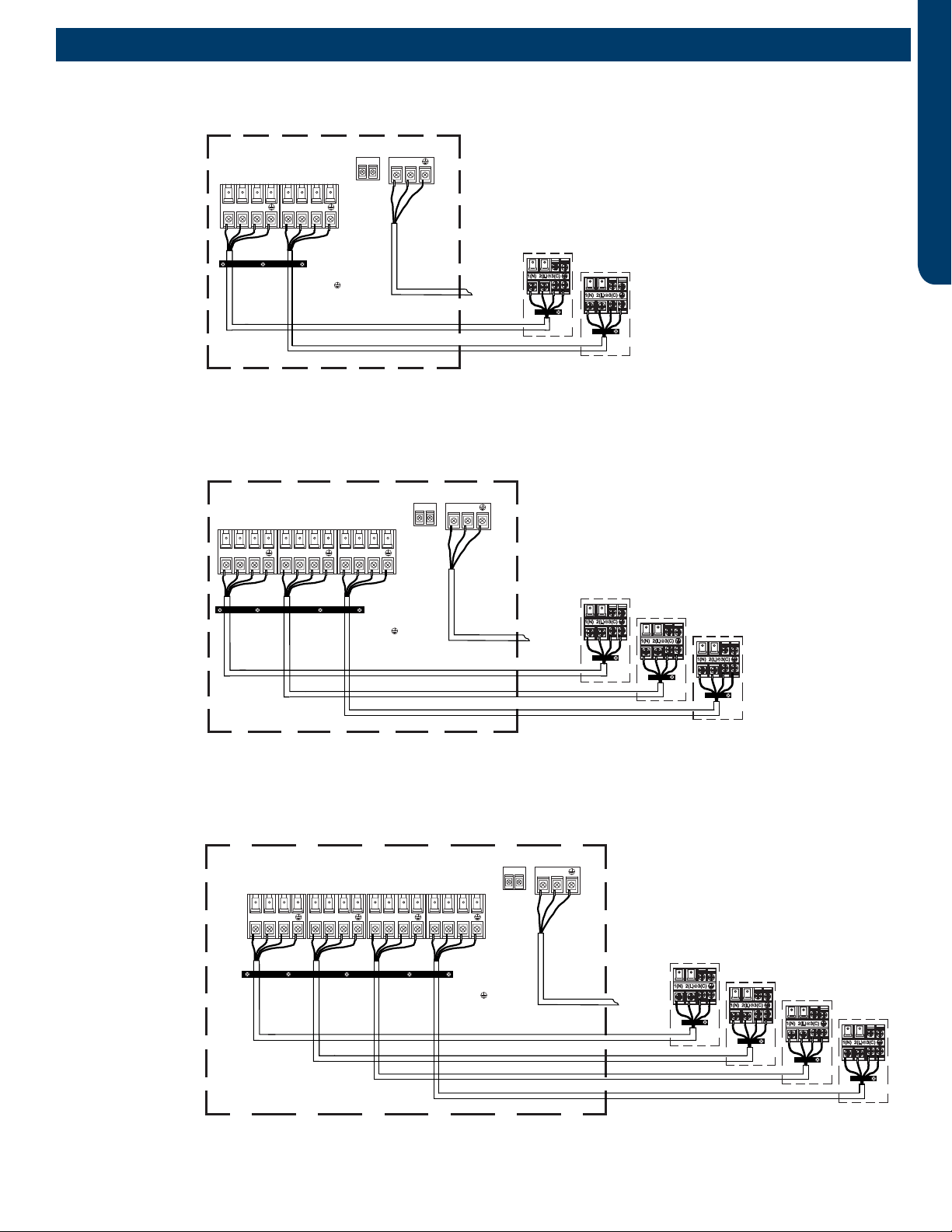
REFERENCE INFORMATION PAGE 43
ENGLISH
Outdoor/Indoor Wiring Connections
2U18MS2HDA
ASH218JCDDA
Outdoor unit
Central
Control
Supply Power
Wiring
3
2
1)
(N)
(L )
(C3
2
1)
(N)
(L )
(C
Control Wiring
4 Wire - 14 AWG
Copper Stranded
1
2
3
=White
=Black
=Red
=Green
Sugested Colors
To Service
Disconnect
230 Volt Supply.
1 to L1, 2 to L2.
Indoor unit B
Indoor unit A Indoor unit B
Indoor unit A
2
1)
(N)
(L
C2C1
Outdoor unit
Central
Control
Supply Power
Wiring
3
2
1)
(N)
(L )
(C
3
2
1)
(N)
(L )
(C3
2
1)
(N)
(L )
(C
Control Wiring
4 Wire - 14 AWG
Copper Stranded
1
2
3
=White
=Black
=Red
=Green
Sugested Colors
To Service
Disconnect
230 Volt Supply.
1 to L1, 2 to L2.
Indoor unit B
Indoor unit C
Indoor unit A Indoor unit B Indoor unit C
Indoor unit A
2
1)
(N)
(L
C2C1
Outdoor unit
Central
Control
Supply Power
Wiring
3
2
1)
(N)
(L )
(C
3
2
1)
(N)
(L )
(C
3
2
1)
(N)
(L )
(C3
2
1)
(N)
(L )
(C
Control Wiring
4 Wire - 14 AWG
Copper Stranded
1
2
3
=White
=Black
=Red
=Green
Sugested Colors
To Service
Disconnect
230 Volt Supply.
1 to L1, 2 to L2.
Indoor unit B
Indoor unit C
Indoor unit D
Indoor unit A Indoor unit B Indoor unit C
Indoor unit D
Indoor unit A
2
1)
(N)
(L
C2C1
3U24MS2HDA
ASH324JCDDA
Outdoor unit
Central
Control
Supply Power
Wiring
3
2
1)
(N)
(L )
(C3
2
1)
(N)
(L )
(C
Control Wiring
4 Wire - 14 AWG
Copper Stranded
1
2
3
=White
=Black
=Red
=Green
Sugested Colors
To Service
Disconnect
230 Volt Supply.
1 to L1, 2 to L2.
Indoor unit B
Indoor unit A Indoor unit B
Indoor unit A
2
1)
(N)
(L
C2C1
Outdoor unit
Central
Control
Supply Power
Wiring
3
2
1)
(N)
(L )
(C
3
2
1)
(N)
(L )
(C3
2
1)
(N)
(L )
(C
Control Wiring
4 Wire - 14 AWG
Copper Stranded
1
2
3
=White
=Black
=Red
=Green
Sugested Colors
To Service
Disconnect
230 Volt Supply.
1 to L1, 2 to L2.
Indoor unit B
Indoor unit C
Indoor unit A Indoor unit B Indoor unit C
Indoor unit A
2
1)
(N)
(L
C2C1
Outdoor unit
Central
Control
Supply Power
Wiring
3
2
1)
(N)
(L )
(C
3
2
1)
(N)
(L )
(C
3
2
1)
(N)
(L )
(C3
2
1)
(N)
(L )
(C
Control Wiring
4 Wire - 14 AWG
Copper Stranded
1
2
3
=White
=Black
=Red
=Green
Sugested Colors
To Service
Disconnect
230 Volt Supply.
1 to L1, 2 to L2.
Indoor unit B
Indoor unit C
Indoor unit D
Indoor unit A Indoor unit B Indoor unit C
Indoor unit D
Indoor unit A
2
1)
(N)
(L
C2C1
4U36MS2HDA
ASH436JCDDA
Outdoor unit
Central
Control
Supply Power
Wiring
3
2
1)
(N)
(L )
(C3
2
1)
(N)
(L )
(C
Control Wiring
4 Wire - 14 AWG
Copper Stranded
1
2
3
=White
=Black
=Red
=Green
Sugested Colors
To Service
Disconnect
230 Volt Supply.
1 to L1, 2 to L2.
Indoor unit B
Indoor unit A Indoor unit B
Indoor unit A
2
1)
(N)
(L
C2C1
Outdoor unit
Central
Control
Supply Power
Wiring
3
2
1)
(N)
(L )
(C
3
2
1)
(N)
(L )
(C3
2
1)
(N)
(L )
(C
Control Wiring
4 Wire - 14 AWG
Copper Stranded
1
2
3
=White
=Black
=Red
=Green
Sugested Colors
To Service
Disconnect
230 Volt Supply.
1 to L1, 2 to L2.
Indoor unit B
Indoor unit C
Indoor unit A Indoor unit B Indoor unit C
Indoor unit A
2
1)
(N)
(L
C2C1
Outdoor unit
Central
Control
Supply Power
Wiring
3
2
1)
(N)
(L )
(C
3
2
1)
(N)
(L )
(C
3
2
1)
(N)
(L )
(C3
2
1)
(N)
(L )
(C
Control Wiring
4 Wire - 14 AWG
Copper Stranded
1
2
3
=White
=Black
=Red
=Green
Sugested Colors
To Service
Disconnect
230 Volt Supply.
1 to L1, 2 to L2.
Indoor unit B
Indoor unit C
Indoor unit D
Indoor unit A Indoor unit B Indoor unit C
Indoor unit D
Indoor unit A
2
1)
(N)
(L
C2C1
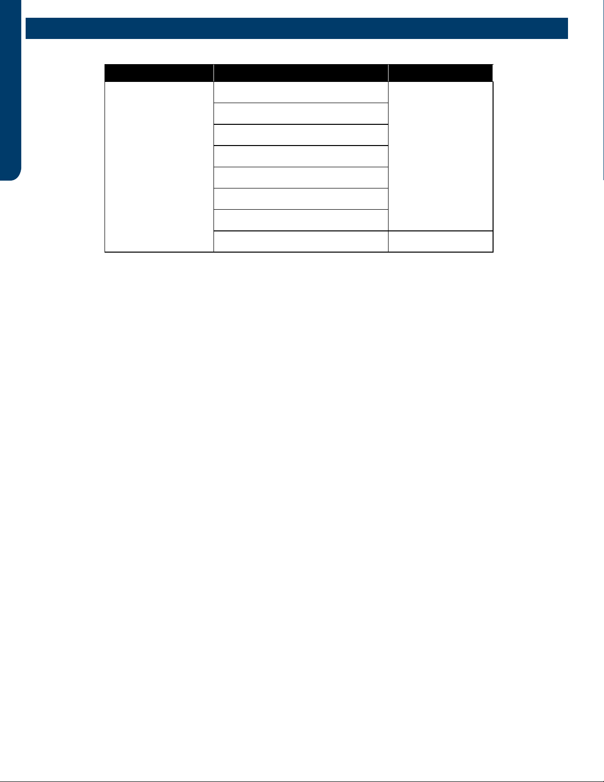
REFERENCE INFORMATION
PAGE 44
ENGLISH
Sensor Resistance Table
Model Sensor Name Resistance
2U18MS2HDA
3U24MS2HDA
4U36MS2HDA
ASH218JCDDA
ASH324JCDDA
ASH436JCDDA
Branch Vapor Sensor (Tc1)
10KΩ @ 77°F
Branch Liquid Sensor (Tc2)
Outdoor Ambient Sensor (Ta)
Condensing Sensor (Tc)
Compressor Suction Sensor (Ts)
Defrost Sensor (Te)
Inverter Module Sensor (Tn)
Compressor Discharge (Td) 50KΩ @ 176°F
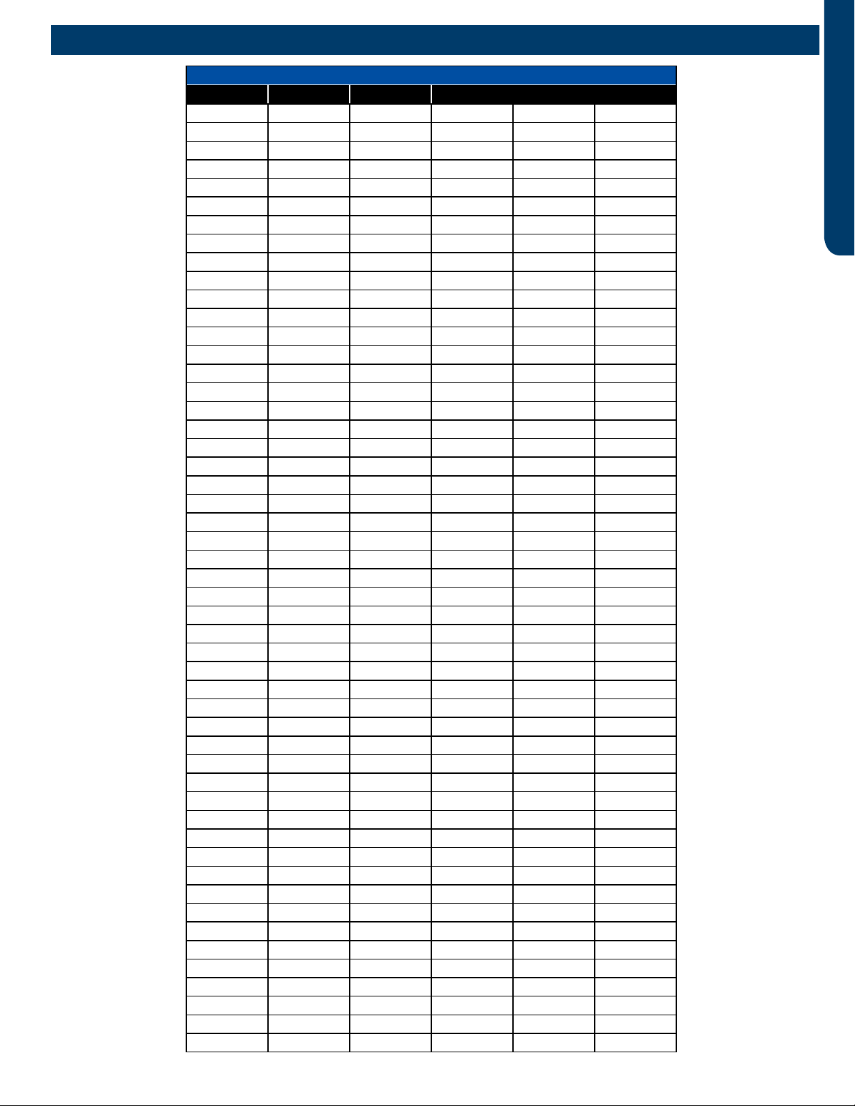
REFERENCE INFORMATION PAGE 45
ENGLISH
10KΩ Sensors
T (°F) T (°C) KΩ T (°F) T (°C) KΩ
-4.0 -20 90.79 87.8 31 7.83
-2.2 -19 85.72 89.6 32 7.52
-0.4 -18 80.96 91.4 33 7.23
1.4 -17 76.51 93.2 34 6.95
3.2 -16 72.33 95.0 35 6.68
5.0 -15 68.41 96.8 36 5.43
6.8 -14 64.73 98.6 37 5.60
8.6 -13 61.27 100.4 38 5.59
10.4 -12 58.02 102.2 39 5.73
12.2 -11 54.97 104.0 40 5.52
14.0 -10 52.10 105.8 41 5.32
15.8 -9 49.40 107.6 42 5.12
17.6 -8 46.86 109.4 43 4.93
19.4 -7 44.46 111.2 44 4.90
21.2 -6 42.21 113.0 45 4.58
23.0 -5 40.08 114.8 46 4.42
24.8 -4 38.08 116.6 47 4.26
26.6 -3 36.19 118.4 48 4.11
28.4 -2 34.41 120.2 49 3.97
30.2 -1 32.73 122.0 50 3.83
32.0 0 31.14 123.8 51 3.70
33.8 1 29.64 125.6 52 3.57
35.6 2 28.22 127.4 53 3.45
37.4 3 26.40 129.2 54 3.33
39.2 425.61 131.0 55 3.22
41.0 524.41 132.8 56 3.11
42.8 6 23.27 134.6 57 3.11
44.6 722.20 136.4 58 2.90
46.4 8 21.18 138.2 59 2.81
48.2 920.21 140.0 60 2.72
50.0 10 19.30 141.8 61 2.63
51.8 11 18.43 143.6 62 2.54
53.6 12 17.61 145.4 63 2.49
55.4 13 16.83 147.2 64 2.38
57.2 14 16.09 149.0 65 2.30
59.0 15 15.38 150.8 66 2.23
60.8 16 14.71 152.6 67 2.16
62.6 17 14.08 154.4 68 2.09
64.4 18 13.48 156.2 69 2.03
66.2 19 12.90 158.0 70 1.96
68.0 20 12.36 159.8 71 1.90
69.8 21 11.84 161.6 72 1.85
71.6 22 11.34 163.4 73 1.79
73.4 23 10.87 165.2 74 1.73
75.2 24 10.43 167.0 75 1.68
77.0 25 10.00 168.8 76 1.63
78.8 26 9.59 170.6 77 1.58
80.6 27 9.21 172.4 78 1.54
82.4 28 8.84 174.2 79 1.49
84.2 29 8.48 176.0 80 1.45
86.0 30 8.15
Sensor Resistance Tables
REFERENCE INFORMATION
PAGE 46
ENGLISH
50KΩ Sensors
T (°F) T (°C) KΩ T (°F) T (°C) KΩ
32.0 0 1877.0 89.6 32 366.0
33.8 1 1775.0 91.4 33 349.3
35.6 2 1680.0 93.2 34 333.5
37.4 31590.0 95.0 35 318.4
39.2 41506.0 96.8 36 304.1
41.0 51426.0 98.6 37 290.5
42.8 6 1351.0 100.4 38 277.6
44.6 71280.0 102.2 39 265.3
46.4 8 1214.0 104.0 40 253.6
48.2 9 1151.0 105.8 41 242.5
50.0 10 1092.0 107.6 42 232.0
51.8 11 1036.0 109.4 43 221.9
53.6 12 983.2 111.2 44 212.3
55.4 13 933.4 113.0 45 203.2
57.2 14 886.4 114.8 46 194.5
59.0 15 841.9 116.6 47 186.3
60.8 16 800.0 118.4 48 178.4
62.6 17 760.8 120.2 49 170.9
64.4 18 722.8 122.0 50 163.7
66.2 19 687.3 123.8 51 155.9
68.0 20 653.8 125.6 52 150.4
69.8 21 622.0 127.4 53 144.2
71.6 22 592.0 129.2 54 138.3
73.4 23 553.6 131.0 55 132.7
75.2 24 536.6 132.8 56 127.3
77.0 25 511.1 134.6 57 122.1
78.8 26 486.9 136.4 58 117.2
80.6 27 464.0 138.2 59 112.5
82.4 28 442.3 140.0 60 108.0
84.2 29 421.7 141.8 61 103.8
86.0 30 402.1 143.6 62 99.7
87.8 31 383.6
Sensor Resistance Tables
[This page intentionally left blank.]
SYJS-04-2019REV.D
GE Appliances, A Haier Company
Appliance Park, Louisville, KY 40225
©2022 GE Appliances, A Haier Company
Rev Date: Mar. 2022
Model#:
2U18MS2HDA
3U24MS2HDA
4U36MS2HDA
ASH218JCDDA
ASH324JCDDA
ASH436JCDDA