Loading ...
Loading ...
Loading ...
14 English
If nothing is displayed in the remote controller, check the follow-
ing items before attempting a diagnosis based on the malfunc-
tion code, as they might be a cause.
Disconnected or incorrect wiring (between power supply and •
the outdoor unit, between the outdoor and indoor units, and
between the indoor unit and the remote controller)
Burnt out indoor or outdoor unit fuse •
“ •
” will be displayed for a few seconds on the remote
controller immediately after the power is turned on.
This display indicates that the remote controller is being
checked to see whether it is ok or not, and does not indicate
a malfunction.
Diagnose with the display on the liquid crystal display
remote controller.
1. With the wired remote controller. (NOTE 1)
When the operation stops due to trouble, operation lamp
fl ashed, and “
” and the malfunction code are indicated
in the liquid crystal display. In such a case, diagnose the fault
contents by referning to the table on the malfunction code list
it case of group control, the unit No. is displayed so that the
indoor unit No. with the trouble can be recognizde. (NOTE 2).
2. With the wireless remote controller.
(Refer also to the operation manual attached to the wireless
remote controller)
When the operation stops due to trouble. the display on the
indoor unit fl ashes. In such a case, diagnose the fault con-
tents with the table on the malfunction code list looking for
the malfunction code which can be found by following proce-
dures. (NOTE 2)
(1) Press the INSPECTION /TEST OPERATION button,
“
” is displayed and “ 0 ” fl ashes.
(2) Press the PROGRAMMING TIME button and fi nd the
unit No. which stopped due to trouble.
Number of beeps
3 short beeps Perform all the following
operations
1 short beep Perform (3) and (6)
1 long beep No trouble
(3) Press the OPERATION MODE SELECTOR button and
upper fi gure of the malfunction code fl ashes.
(4) Continue pressing the PROGRAMMING TIME button
unit it makes 2 short beeps and fi nd the upper code.
(5) Press the OPERATION MODE SELECTOR button and
lower fi gure of the malfunction code fl ashes.
(6) Continue pressing the PROGRAMMING TIME button
unit it makes a long beep and fi nd the lower code.
A long beep indicate the malfunction code. •
NOTE
1. In case wired remote controller. Press the INSPECTION /
TEST OPERATION button on remote controller, “
“
starts fl ashing.
2. Keep down the ON/OFF button for 5 seconds or longer in
the inspection mode and the above trouble history disap-
pears, after the trouble code goes on and off twice, followed
by the code “
”(normal).
The display changes from the inspection mode to the nor-
mal mode.
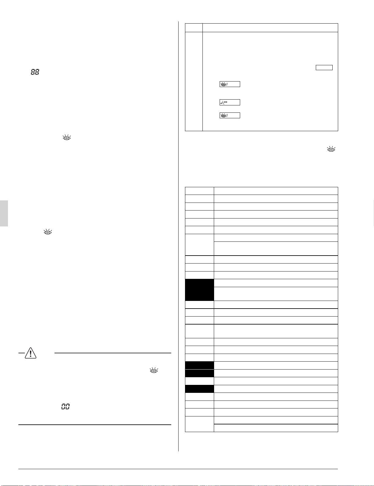
Order Operation
(1) Open gas side stop valve.
(2) Open liquid side stop valve.
(3) Electrify crank case heater for 6 hours.
(4)
Set to cooling with the remote controller and push “
ON/OFF
”
button to start operation.
(5)
Push“
TEST
”button twice and operate in TEST OPERA-
TION MODE for 3 minutes.
(6) Push“
SWING
”button and confi rm its operation.
(7) Push“
TEST
”button and operate normally.
(8) Confi rm its function according to the operation manual.
MALFUNCTION CODE12-2
For places where the malfunction code is left blank, the “ • ”
indication is not displayed. Though the system continues
operating, be sure to inspect the system and make repairs as
necessary.
Depending on the type of indoor or outdoor unit, the malfunc- •
tion code may or may not be displayed.
Code Malfunction/Remarks
A1 Indoor unit's PC board faulty
A3 Condensate level abnormal
A6 Indoor fan motor overloaded, overcurrent or locked.
A7 Air fl ow direction adjust motor is fault.
A9 Drive for electronic expansion valve is fault.
AJ
Type set improper
Capacity data is wrongly preset. Or there is nothing pro-
grammed in the data hold IC.
C4 Sensor R2T for heat exchanger temperature is fault.
C5 Sensor R3T for heat exchanger temperature is fault.
C9 Sensor R1T for suction air temperature is fault.
CJ
Sensor for remote controller is fault.
The remote controller ther
mistor does not function, but
the system thermo run is possible.
E3 High pressure abnormal (outdoor unit)
E4 Low pressure abnormal (outdoor unit)
E5 Compressor motor lock malfunction
E7
Outdoor fan motor lock malfunction
Outdoor fan instantaneous overcurrent malfunction
E9 Electronic expansion valve faulty (outdoor unit)
F3 Discharge pipe temperature abnormal (outdoor unit)
F6 The refrigerant is overcharged.
H9 Outdoor air thermistor faulty (outdoor unit)
J3 Discharge pipe thermistor faulty (outdoor unit)
J5
Suction pipe thermistor faulty (outdoor unit)
J6 Heat exchanger thermistor faulty (outdoor unit)
J9
Sensor for heat exchanger is fault.
JA Sensor for high pressure is fault.
JC Sensor for low pressure is fault.
L4
Overheated heat-radiating fi n (outdoor)
Inverter cooling defect.
3PN0624012MEN.indd143PN0624012MEN.indd14 2008/12/2613:22:542008/12/2613:22:54
Loading ...
Loading ...
Loading ...