Loading ...
Loading ...
Loading ...
10 English
Keep in mind that it will become the cause of getting drain •
pipe blocked if water collects on drain pipe.
ELECTRIC WIRING WORK 8.
GENERAL INSTRUCTIONS 8-1
All fi eld supplied parts and materials and electric works must •
conform to local codes.
Use copper wire only. •
For electric wiring work, refer to also “Wiring diagram label” •
attached to the control box lid.
For remote controller wiring details, refer to the installation •
manual attached to the remote controller.
All wires must be performed by an authorized electrician. •
An earth leakage circuit breaker capable of shutting down •
power supply to the entire system must be installed.
Refer to the installation manual attached to the outdoor unit •
for the size of power supply wiring connected to the outdoor
unit, the capacity of the circuit breaker and switch, and wiring
instructions.
Be sure to ground the air conditioner. •
DANGER
Do not ground units to water pipes, telephone wires or •
lightning rods because incomplete grounding could cause a
severe shock hazard resulting in severe injury or death, and
to gas pipes because a gas leak could result in an explosion
which could lead to severe injury or death.
ELECTRICAL CHARACTERISTICS8-2
Units Power supply Fan motor
Model Hz Volts
Voltage
range
MCA MFA W FLA
FHQ18PVJU
60 208-230V
Max. 253V
Min. 187V
1.3 15 130 1.0
FHQ24PVJU 1.3 15 130 1.0
FHQ30PVJU 1.3 15 130 1.0
MCA : Min. Circuit Amps (A); MFA : Max. Fuse Amps (A)
W: Fan Motor Rated Output (W); FLA : Full Load Amps (A)
SPECIFICATIONS FOR FIELD SUPPLIED FUSES 8-3
AND WIRES
Model
Power supply wiring
Remote controller wiring
Transmission wiring
Field fuses
Size Wire Size
FHQ18PVJU
15A
Wire size must
comply with
local codes.
Sheathed wire
(2 wires)
AWG 18-16 FHQ24PVJU
FHQ30PVJU
Allowable length of transmission wire between indoor/outdoor
units and between the indoor unit and the remote controller wire
are as follows.
(1) Outdoor unit - Indoor unit : Max. 3280 ft.
(2) Indoor unit - Remote controller : Max. 1640 ft.
WIRING EXAMPLE AND HOW TO SET 9.
THE REMOTE CONTROLLER
HOW TO CONNECT WIRES9-1
CAUTION
Even if the control box lid is removed, pull the remote control- •
ler wire, transmission wire and the power supply wire inside
the unit using conduits for each, so that the wires do not come
into contact with the opening section of the metal casing.
Pass conduits through the wall and secure along with the •
refrigerant pipe in order to prevent external pressure being
applied to transmission wire and power supply wire.
To avoid short circuits in the electric parts box, be sure to apply •
the sealing material or putty (not included) to the wiring hole to
prevent the infi ltration of water, insects or other small creatures.
Arrange the wires and fi x a lid fi rmly so that the lid does not •
fl oat during wiring work.
Do not clamp remote controller wire and transmission wire •
together with power supply wire. Doing so may cause mal-
function.
Remote controller wire, transmission wire and power supply •
wire should be located at least 5 in. from other electric wires.
Not following this guideline may result in malfunction due to
electrical noise.
<Method of wiring power supply, units and connect-
ing remote controller wiring> (Refer to Fig. 26)
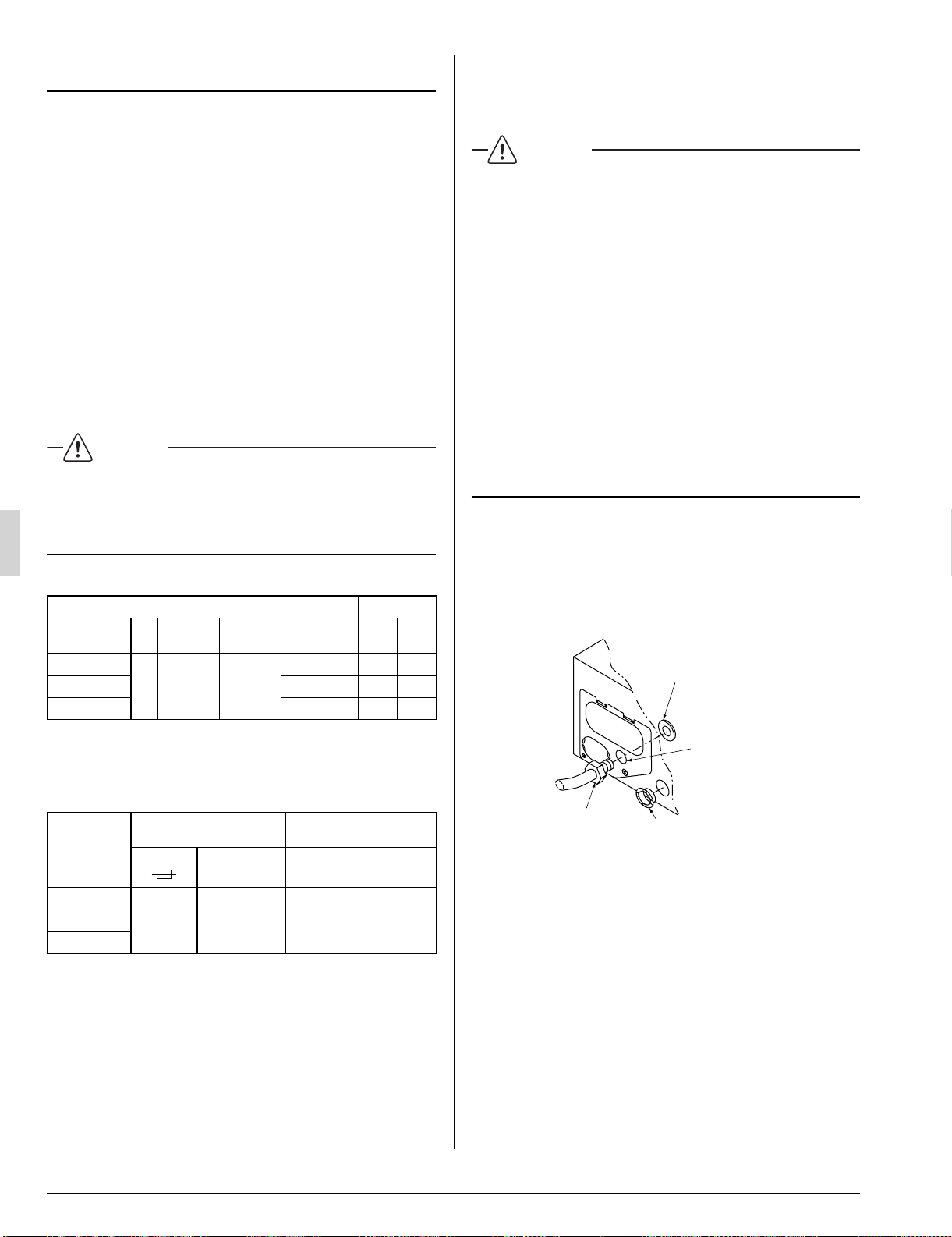
Attaching the resin bush •
Attach the resin bush (10) for remote controller wiring.
Installlation of conduit •
Insert the conduit for power supply wire in the conduit hole,
and fi x it with the lock nut.
Resin bush (10)
Lock nut
Conduit
Conduit hole
Fig. 25
Power supply wire •
Holding the control box lid, loosen the 2 securing screws,
remove the control box lid, match up the phases on the power
supply terminal block inside (2P), and make the connections.
After this is done, use the attached clamp (4) to bind wire
between units to the anchor point. (Refer to Fig. 27)
Remote controller wire and transmission wire •
Holding the control box lid, loosen the 2 securing screws,
remove the control box lid.
Thread the remote controller wire and transmission wire
through the insulating tube (11) and secure with the clamp
(4), and cut off the insulating tube (11) to suitable length. Pull
the wires inside through resin bush and connect the wires to
the transmission terminal block (6P) inside the control box.
After connecting, use the clamp (4) to bind the remote con-
troller wire together with the transmission wire to the anchor.
(Refer to Fig. 26, 27, 28)
3PN0624012MEN.indd103PN0624012MEN.indd10 2008/12/2613:22:532008/12/2613:22:53
Loading ...
Loading ...
Loading ...