Loading ...
Loading ...
Loading ...
8
ENGLISH
CUSTOMER SERVICE
KLEIN TOOLS, INC.
450 Bond Street Lincolnshire, IL 60069 1-800-553-4676
[email protected] www.kleintools.com
CLEANING
Be sure tester is turned off and wipe with a clean, dry lint-free
cloth.
Do not use abrasive cleaners or solvents.
STORAGE
Remove the batteries when tester is not in use for a prolonged period
of time. Do not expose to high temperatures or humidity. After a period
of storage in extreme conditions exceeding the limits mentioned in
the General Specifications section, allow the tester to return to normal
operating conditions before using.
WARRANTY
www.kleintools.com/warranty
DISPOSAL / RECYCLE
Do not place equipment and its accessories in the trash. Items must
be properly disposed of in accordance with local regulations. Please
see www.epa.gov/recycle for additional information.
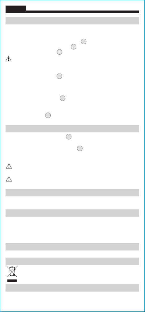
BATTERY REPLACEMENT
When the Battery Life Indicator
C
turns red, the batteries must be
replaced.
1. Loosen screw from battery cover
8
.
2. Replace 3 x AAA batteries (note proper polarity).
3. Replace battery door and fasten securely with screw.
T
o avoid risk of electric shock, unplug from any voltage source
before removing battery door.
To avoid risk of electric shock, do not operate tester while
battery door is removed.
OPERATING INSTRUCTIONS
TEST LOAD FUNCTION
Power On the tester and plug into the outlet to be tested, noting the
wiring conditions. The wiring condition
E
should indicate "CORRECT
WIRING", the
"ENERGIZED" Indicator
3
should be illuminated, and the
Circuit Energized Indicator
B
should be displayed.
If the tester indicates that the outlet is not wired correctly, DO NOT
attempt to initiate an electrical testing event. Consult a quali ed
electrician.
Press the Load Test button
7
, and the 12A, 15A, and 20A test load
voltage and percentage voltage drop will appear on the screen.
NOTE:
If
the voltage drop is greater than 5%, the background color will change
to red to indicate a large voltage drop.
NOTE: The Load Test button
7
will be deactivated if the tester
detects that the electrical outlet is not wired correctly.
NOTE: During a Load test, a message may display that the tester
needs to cool down
J
. A successive Load test cannot be initiated
until the unit cools down and the message is no longer displayed.
Loading ...
Loading ...
Loading ...