User Manual
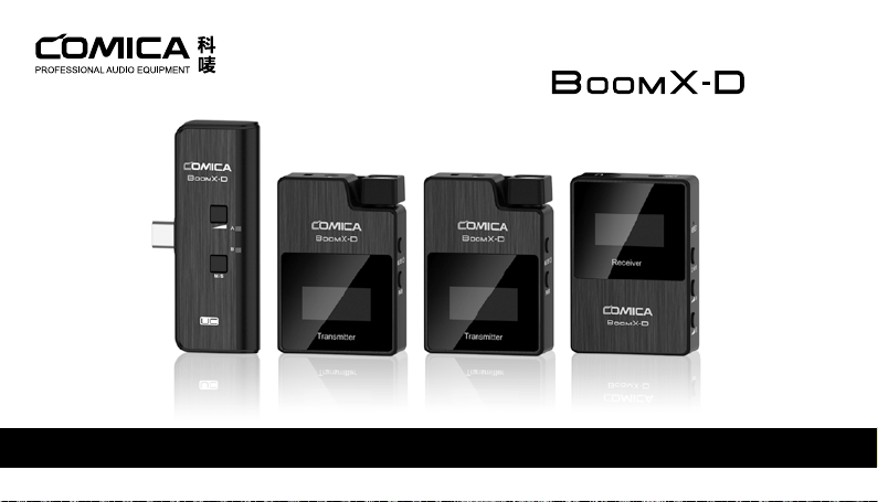
2.4G Digital 1-Trigger-2 Wireless Microphone

Foreword
Main Features
Thanks for purchasing COMICA BoomX-D 2.4G Digital 1-Trigger-2 Wireless Microphone.
To ensure bring you a good using experience, please read this manual book carefully before using and correctly install and operate.
. 2.4G Digital Wireless, Global Free Frequency
. Dual Transmitters Triggered by One Receiver
. Visual Power, Audio Dynamic Monitor and Other Display Functions
. Internal and External MIC Two Input Modes
. Mono/Stereo Switchable Output Modes
. Real-time Audio Monitor
. Broadcasting Quality Audio
. RF Technology, Auto Freq. Adjustment, Stable Transmission
. Low Latency < 20ms
. Working Range Up to 50m
. Designed with Multi-functional Belt Clip and Compact
Notice
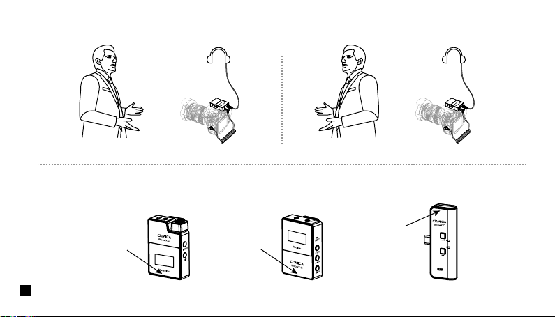
Due to 2.4G wireless characteristics, please keep face to face when use it, and don’t turn your back to the receiver, otherwise it is easy
to generate breakpoints, which is a normal phenomenon.
Don't block the antenna position to avoid any poor signal generated.
Please attention that it can not realize STEREO function when in one-trigger-one mode.
When using on mobile phone, please turn o WIFI and Bluetooth to avoid 2.4G wireless interference.
This product belongs to high-precision instruments, please avoid falling, collision or pounding.
Do not use this equipment in the vicinity of heat source or interference source, such as radiator, oven, refrigerator or air conditioner,
smartphone or next to the WIFI AP.
If the pick-up distance is close or when used outdoors, please put on the wind mu to prevent sound burst or reduce wind noise.
Do not use the equipment in rain or in a damp environment to avoid short-circuit danger.
Please keep the product in a dry environment.
1
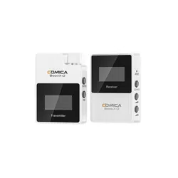
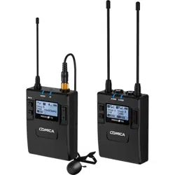
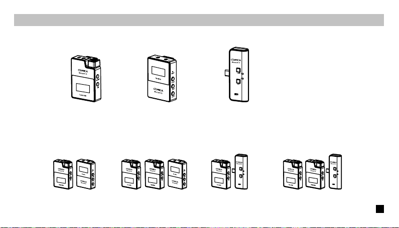
UC Receiver (UC RX)Receiver (RX)Transmitter(TX)
Please keep face to face when use it, and don’t turn your back to the receiver, otherwise it is easy to generate breakpoints.
Don't block the antenna position to avoid any poor signal generated.
Face to receiver (correct)
Antenna position
Antenna position
Antenna position
Back to receiver (incorrect)
2
Packing List
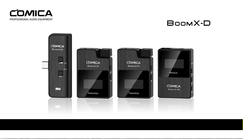
D1 = TX + RX D2 = TX + TX + RX UC1 = TX + UC RX UC2 = TX + TX + UC RX
UC Receiver (UC RX)Receiver (RX) Transmitter(TX)
Multiple Selections:
Main Parts:
3
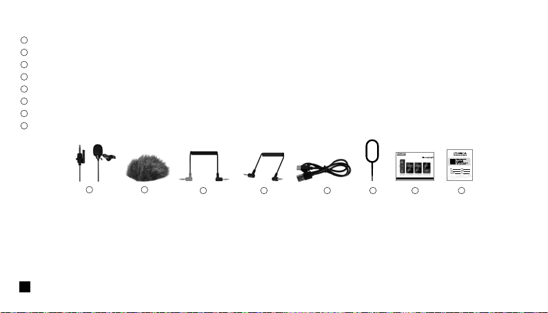
3.5mm Mic Audio Input Cable
Wind Mu
3.5mm TRS-TRRS Audio Cable
3.5mm TRS-TRS Audio Cable
USB A-USB C Charging Cable
Reset Pin
User Manual
Warranty Card
The accessories of each combination include:
Accessories:
① + ② + ③ + ④ + ⑤ + ⑥ + ⑦ + ⑧
D1=
①x2 + ②x2 + ③ + ④ + ⑤ + ⑥ + ⑦ + ⑧
D2=
① + ② + ⑤ + ⑥ + ⑦ + ⑧
UC1=
①x2 + ②x2 + ⑤ + ⑥ + ⑦ + ⑧
UC2=
7 86543
21
1
2
3
4
5
6
7
8
User Manual
2.4G Digital 1-Trigger-2 Wireless Microphone
4
Components and Instruction
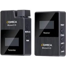
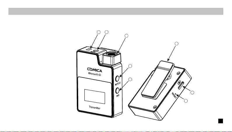
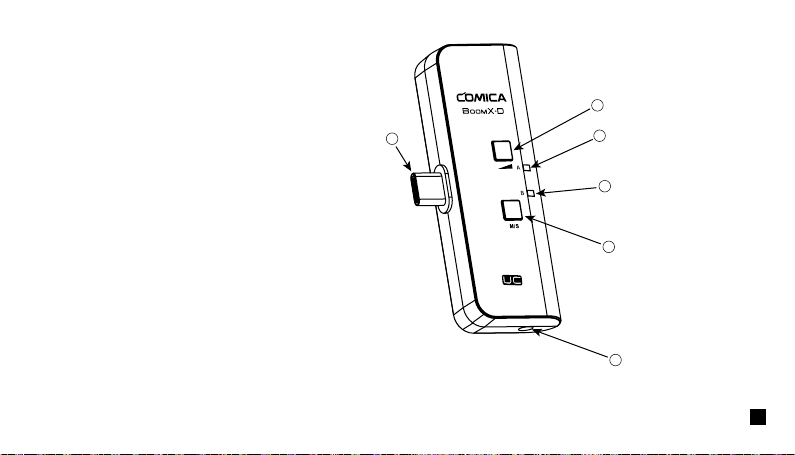
Transmitter (TX)
1. External Mic Locking Buckle
2. 3.5mm TRS Port of External Mic
3. Internal Mic
4. Power / Muting Button
5. Pair Button
6. Belt Clip
7. USB-C Charging Port
8. Reset Hole
2
3
6
4
7
8
5
1
5
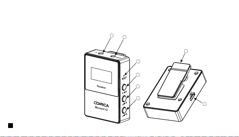
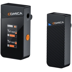
Receiver (RX)
1. 3.5mm TRS/TRRS Monitoring Headphone Port
2. 3.5mm TRS Audio Input Port
3. Reset Hole
4. Power and M/S Button
5. A Channel Output Gain Control Button
6. B Channel Output Gain Control Button
7. Belt Clip
8. USB-C Charging Port
2
3
6
4
7
8
5
1
6
UC Receiver (UC RX)
1. USB-C Connector
2. Output Volume Adjustment Button
3. Group A Working Status Indicator
4. Group B Working Status Indicator
5. M/S Adjustment Button
6. 3.5mm TRS/TRRS Monitoring Headphone Port
2
3
4
5
6
1
7
Installation
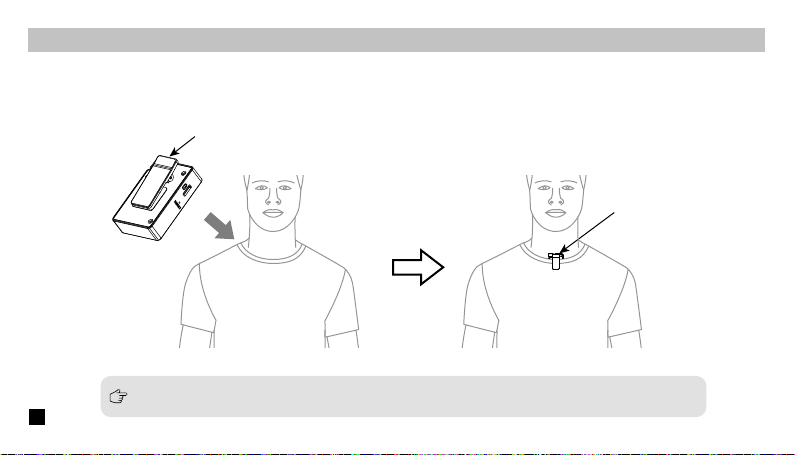
Transmitter (TX)
1.Use internal microphone :
Install the transmitter on the collar through the belt clip so that the internal microphone points in the direction of the sound source.
Internal Mic
Belt Clip
For better concealment during use, it is recommended that the belt clip be fixed and used outwards.
8
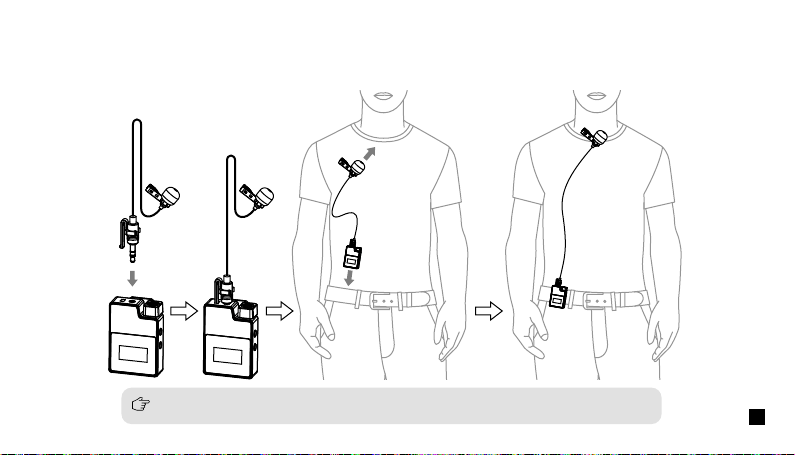
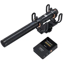
2.Use external microphone:
Insert the 3.5mm TRS microphone input cable into the transmitter's 3.5mm TRS external microphone port and tighten it, then clip the
transmitter to the belt through the belt clip and clip the lavalier microphone to your collar.
When using an external microphone, the internal microphone is automatically turned o.
9
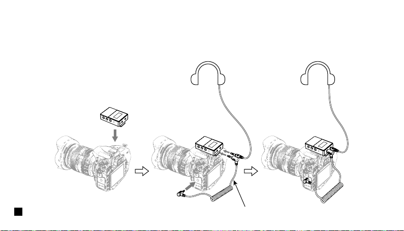
1.Work with Camera:
Fix the receiver through the belt clip to the camera's hot shoe mount, then connect the receiver with camera through the 3.5mm
TRS-TRS audio cable; Insert the headphone into the monitoring headphone port for monitoring.
Receiver (RX)
3.5mm TRS-TRS Audio Cable
10
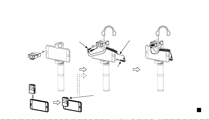
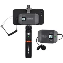
2.Work with Smartphone:
Clip the receiver to the cold shoe mount through the belt clip; Connect the receiver with the mobile phone through the 3.5mm
TRS-TRRS audio cable and pay attention to the access to the audio output jack of the receiver is the 3.5mm TRS plug, and the
access to the mobile phone is the 3.5mm TRRS plug; Insert the headphone to the 3.5 mm TRS/TRRS monitoring headphone port for
monitoring.
TRRS Plug
TRS Plug
3.5mm TRS-TRRS Audio Cable
In the absence of a mobile phone holder, the receiver can be clamped
to the mobile phone through the belt clip, and the installation methods
of other accessories are the same as above.
11
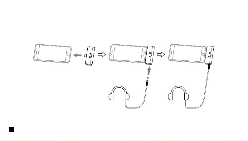
Insert the UC receiver (UC RX) into the USB-C port of the phone; Insert the headphone into the 3.5 mm TRS/TRRS monitoring
headphone port for monitoring.
UC Receiver (UC RX)
12
Function and Usage
Transmitter (TX)
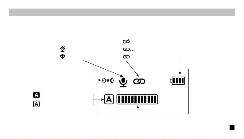
1.Screen Display Instruction:
A/B Channel Microphone Audio Dynamic Bar
Muting
Microphone Normal Working
Unpaired
in the Pairing
Paired
Transmitter Battery Status
Signal Strength
A/B Channel is Connected
A/B Channel is not Connected
13
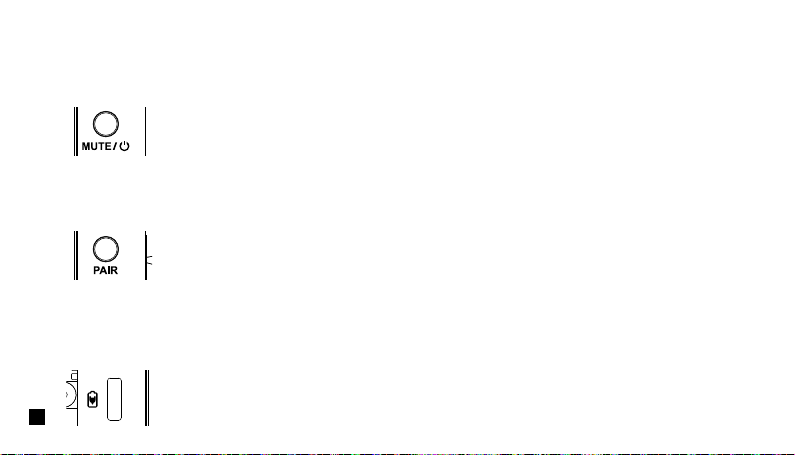
2.Function Introduction:
Long press for On/O; Shot press for muting switch( Muting switch is available only when the screen is on, if the screen is dimmed,
press any button to light up the screen then switch the mute).
2.1. Power/Muting Button
Long press for pairing with receiver (Pairing switch is available only when the screen is on, if the screen is dimmed, press any
button to light up the screen then pairing).
2.2. Pair Button
Connect the transmitter with the power through the USB A-USB C charging cable to charge.
2.3. USB-C Charging Port
14

If there is a abnormal phenomenon such as the device is crash or unable to turn on it, then insert the reset pin into the reset hole
to reset it.
2.4. Reset Hole
Insert the 3.5mm TRS microphone input cable, and you can use the external lavalier microphone for recording. At this time, the
internal microphone of this device is turned o.
2.5. 3.5mm TRS Microphone Port
15
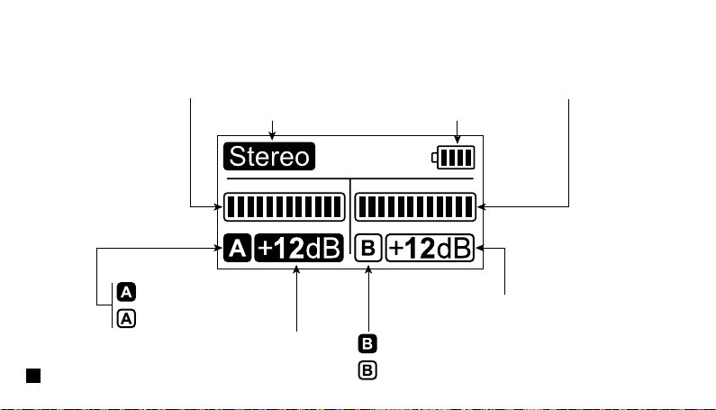
Mono / Stereo Transmitter Battery Status
A channel is connected
A channel is not connected
A Channel Microphone Audio Dynamic Bar B Channel Microphone Audio Dynamic Bar
A Channel Output Gain Control Button
B Channel Output Gain Control Button
B channel is connected
B channel is not connected
Receiver (RX)
1.Screen Display Instruction:
16

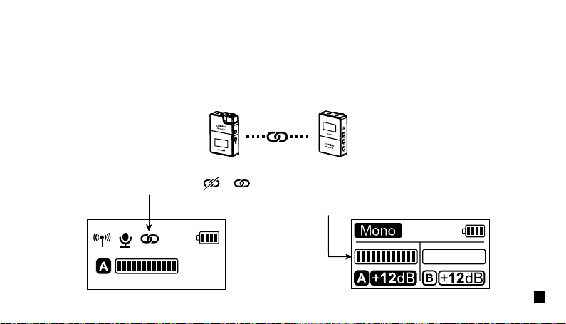
2.Function Introduction:
Long press for On/O; Shot press for mono and stereo mode switch. Please attention that it can not realize STEREO function
when in one-trigger-one mode.
(Mono/Stereo switch is available only when the screen is on, if the screen is dimmed, press any button to light up the screen then
switch the M/S)
2.2. Power and M/S Button
Short press to cyclically adjust the A/ B channel output Volume. It can independently adjust even in the mono mode and is
generally adjusted to the consistent output Volume when in use. (The output Volume adjustment is available only when the screen
is on, and if the screen is dimmed, press any button to light up the screen and then adjust again).
2.3. A/B Channel Output Volume Adjustment Button
If there is a abnormal phenomenon such as the device is crash or unable to turn on it, then insert the reset pin into the reset hole
to reset it.
2.1. Reset Hole
17

Connect the receiver with the power through the USB A-USB C charging cable to charge.
2.4. USB-C Charging Port
Connect with mobile phone through the 3.5mm TRS-TRRS audio cable; Connect with camera through the 3.5mm TRS-TRS audio
cable.
2.5. 3.5mm TRS Audio Output Port
Insert headphone to monitor.
2.6. 3.5mm TRS/TRRS Monitor Headphone Port
18

UC Receiver (UC RX)
Function Introduction:
Insert into the USB-C port of phone to use.
1. USB-C Plug
Short press to cyclically adjust the Volume, and A/B channel is synchronized.
2. Output Volume Adjustment Button
Shot press for Mono/Stereo switch.
3. M/S Button
19

Insert headphone to monitor.
5. 3.5mm TRS/TRRS Monitoring Headphone Port
The indicator is red when unpaired; After paired, the indicator is blue when it's Mono and is purple
when it's Stereo.
4. A/B Working Status Indicator
20
Receiver (RX)
Receiver (RX)
Transmitter (TX)
The transmitter (TX) is pairing with the receiver (RX)
Transmitter (TX)
Turn on the transmitter and receiver within one meter, and then press the pair button for pairing when the transmitter screen is
highlighted.
The screen icon changes from to after pairing
Pairing Method
(All have been paired at the factory. If you need to re-pair, please follow the description)
One-trigger-one:
The microphone audio dynamic bar is available after pairing
21
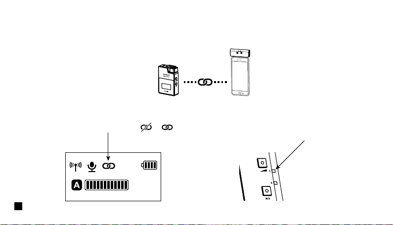
UC Receiver (UC RX)
UC Receiver (UC RX)
The transmitter (TX) is pairing with UC Receiver (UC RX)
The channel indicator on the UC receiver
(UC RX) changes from red to blue or
purple after pairing.
Transmitter (TX)
The screen icon changes from to after pairing
Transmitter (TX)
22
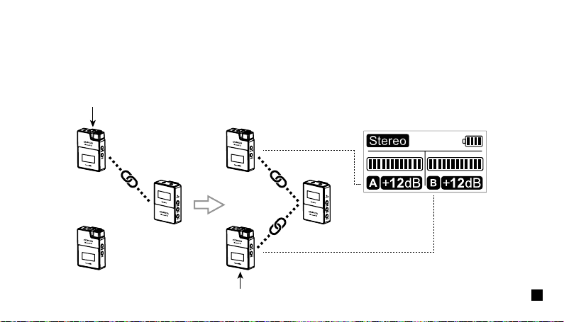
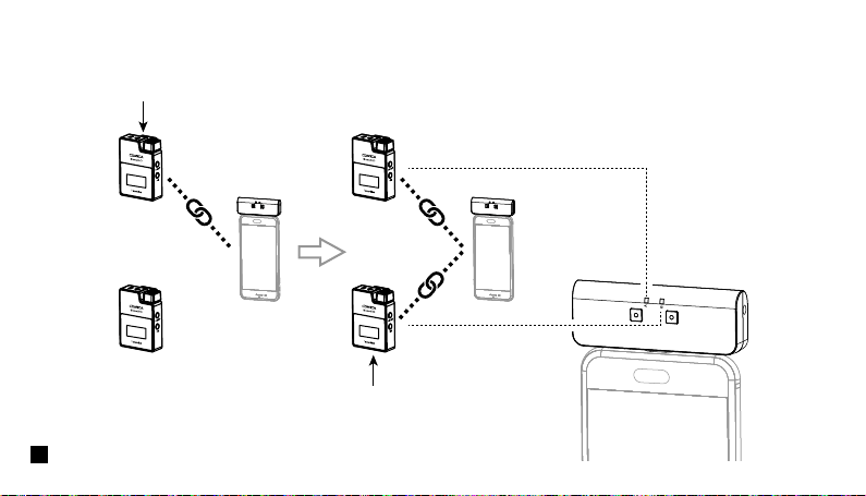
Two transmitters (TX) are pairing with Receiver (RX)
Turn on the transmitter and receiver within one meter, and then long press the pair button of one transmitter to pair the receiver when
the transmitter screen is highlighted. After the pairing is successful, the receiver will designate the first paired transmitter as channel
A.Then long press the pair button of the second transmitter for pairing, and the receiver will designate the second paired transmitter
as channel B after the pairing is successful.Channel A is the left channel, channel B is the right channel.
One-trigger-two:
The first paired transmitter
The second paired transmitter
(A channel )(Left channel) (A channel )(Left channel)
(B channel )(Right channel)
23
Two transmitters (TX) are pairing with UC Receiver (UC RX)
The first paired transmitter
The second paired transmitter
(A channel)(Left channel )
(A channel)(Left channel )
(B channel)(Right channel)
24

Specification
Transmitter (TX)
Wireless Band
Transmitting Power
Receiving Sensitivity
Antenna
Polar Pattern
Frequency Response
Sound Delay
External Mic Input Interface
Battery
Battery Life
Net Weight
Dimension
Operating Temperature
2400 ~ 2483.5MHz
+10dBm
-86dBm
PCB Antenna
Omnidirectional
80Hz ~ 20kHz
<20ms
3.5mm TRS
Built-in Li-ion Battery 300mAh 3.7V
5 Hours
29g
39 x 22 x 55mm
0
℃
~ 50
℃
25

Receiver (RX)
Wireless Band
Transmitting Power
Receiving Sensitivity
Antenna
Audio Output Amplitude
Sound Delay
Audio Output Interface
Monitor Interface
Battery
Battery Life
Net Weight
Dimension
Operating Temperature
2400 ~ 2483.5MHz
+10dBm
-86dBm
PCB Antenna
+0dB ~ +12dB
<20ms
3.5mm TRS
3.5mm TRS/TRRS
Built-in Li-ion Battery 300mAh 3.7V
5 Hours
29g
39 x 22 x 55mm
0
℃
~ 50
℃
26

UC Receiver (UC RX)
Wireless Band
Transmitting Power
Receiving Sensitivity
Antenna
Audio Output Amplitude
Sound Delay
Data Interface
Monitoring Interface
Net Weight
Dimension
Operating Temperature
2400 ~ 2483.5MHz
+10dBm
-86dBm
PCB Antenna
+0dB ~ +12dB
<20ms
USB-C
3.5mm TRS/TRRS
19g
33 x 13 x 70mm
0
℃
~ 50
℃
27

用户使用手册
2.4G数字无线一拖二麦克风