
USER MANUAL
MANUALE D’USO
ES 3080
- ES 3080 MIXER-AMPLIFIER
WITH MP3 PLAYER
- ES 3080 MIXER-AMPLIFICATORE
CON LETTORE MP3


TABLE OF CONTENTS
INDICE
ENGLISH
SAFETY AND OPERATING PRECAUTIONS
DESCRIPTION
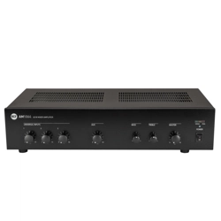
FRONT PANEL
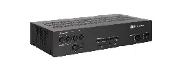
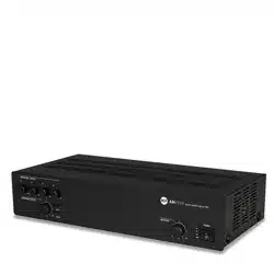
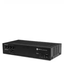
REAR PANEL
MP3 PLAYER
AMPLIFIER OPERATION
SPEAKER CONNECTION
POWER SUPPLY VOLTAGE CHANGE
SPECIFICATIONS
EXAMPLE OF CONNECTIONS
ITALIANO
AVVERTENZE PER LA SICUREZZA
DESCRIZIONE
PANNELLO FRONTALE
PANNELLO POSTERIORE
LETTORE MP3
FUNZIONAMENTO DELL’AMPLIFICATORE
COLLEGAMENTO DEI DIFFUSORI ACUSTICI
CAMBIO TENSIONE DI FUNZIONAMENTO DELL’APPARECCHIO
DATI TECNICI
ESEMPIO COLLEGAMENTI
4
6
6
8
11
13
14
15
16
17
18
20
20
22
25
27
28
29
30
31
ENGLISH
4
IMPORTANT:
Before connecting and using this product, please read this instruction manual carefully and
keep it on hand for future reference.
The manual is to be considered an integral part of this product and must accompany it
when it changes ownership as a reference for correct installation and use as well as for the
safety precautions.
RCF S.p.A. will not assume any responsibility for the incorrect installation and / or use of
this product.
WARNING:
or humidity.
SAFETY PRECAUTIONS
1. All the precautions, in particular the safety ones, must be read with special attention, as
they provide important information.
2. POWER SUPPLY FROM MAINS
connect this product when its power cord is plugged in.
b) Before powering up, make sure that all the connections have been made correctly and
the voltage of your mains corresponds to the voltage shown on the rating plate on the
unit, if not, please contact your RCF dealer.
c) The metallic parts of the unit are earthed by means of the power cord.
An apparatus with CLASS I construction shall be connected to a mains socket outlet
with a protective earthing connection.
d) Protect the power cord from damage.
Make sure it cannot be stepped on or crushed by objects.
e) To prevent the risk of electric shock, never open the product: there are no parts inside
that the user needs to access.
Appliance coupler is used to disconnect device from MAIN power. This device shall
remain readily accessible after the installation.
3
. Make sure that no objects or liquids can get into this product, as this may cause a short
circuit.
apparatus.
4.
described in this manual.
occur:
- The product does not function (or functions in an anomalous way).
- The power supply cable has been damaged.
- Objects or liquids have got in the unit.
- The product has been subject to a heavy impact.
5. If this product is not used for a long period, disconnect its power cord.
IMPORTANT
WARNING
SAFETY AND OPERATING PRECAUTIONS

5
ENGLISH
6. If this product begins emitting any strange odours or smoke, switch it off immediately
and disconnect its power cord.
7. The terminals marked with the symbol
are HAZARDOUS LIVE and their connection
is to be made by an INSTRUCTED PERSON or the use of ready-made cables is required.
8. Do not connect this product to any equipment or accessories not foreseen.
For suspended installation, only use the dedicated anchoring points and do not try to hang
this product by using elements that are unsuitable or not specic for this purpose.
Also check the suitability of the support surface to which the product is anchored (wall,
ceiling, structure, etc.), and the components used for attachment (screw anchors, screws,
brackets not supplied by RCF etc.), which must guarantee the security of the system /
installation over time, also considering, for example, the mechanical vibrations normally
generated by transducers.
To prevent the risk of falling equipment, do not stack multiple units of this product unless
this possibility is specied in the user manual.
9. RCF S.p.A. strongly recommends this product is only installed by professional
qualied installers (or specialised rms) who can ensure correct installation
and certify it according to the regulations in force.
The entire audio system must comply with the current standards and
regulations regarding electrical systems.
10. Supports and trolleys
The equipment should be only used on trolleys or supports, where necessary, that are
recommended by the manufacturer. The equipment / support / trolley assembly must be
moved with extreme caution. Sudden stops, excessive pushing force and uneven oors may
cause the assembly to overturn.
11. Mechanical and electrical factors need to be considered when installing a professional
audio system (in addition to those which are strictly acoustic, such as sound pressure,
angles of coverage, frequency response, etc.).
12. Hearing loss
Exposure to high sound levels can cause permanent hearing loss. The acoustic pressure
level that leads to hearing loss is different from person to person and depends on the
duration of exposure. To prevent potentially dangerous exposure to high levels of acoustic
pressure, anyone who is exposed should use adequate protection devices.
When a transducer capable of producing high sound levels is being used, it is therefore
necessary to wear ear plugs or protective earphones.
See the technical specications in speaker user manuals to know their maximum sound
pressure levels.
13. Do not obstruct the ventilation grilles of the unit. Place this product far from any heat
sources and always ensure adequate air circulation around the ventilation grilles.
14. Do not overload this product. Ensure the amplier output is not short-circuited.
15. Never force the control elements (keys, knobs, etc. ).
16. Do not use solvents, alcohol, benzene or other volatile substances for cleaning the
external parts of this product.
Use a dry cloth.
NOTES ABOUT AUDIO SIGNAL CABLES
To prevent the occurrence of noise on microphone / line signal cables, use screened cables
only and avoid putting them close to:
- Equipment that produces high-intensity electromagnetic elds.
- Mains cables.
- Speaker lines.

6
ENGLISH
DESCRIPTION
for a music source (e.g. CD players, tuners, etc.).
The input 2 also has an RJ 45 port for quick connection of an RCF BM 3001 paging
microphone (through CAT5 cable).
constant voltage line (for speakers having 100 – 70 V transformers).
The input 1 has a signal detection circuit (‘VOX’) for automatic priority.
The inputs 1 and 2 can access the priority through an external command (connected to
either the removable connector or the RJ 45 port).
The MUSIC ON HOLD output directly sends the internal MP3 player signal to additional
useful to improve speech intelligibility.
The internal MP3 player and the AUX INPUT have tone controls (common for both).
Front panel LEDs indicate the device state (ON, PROT), priority circuit enabled (PRIOR) and
the signal level / peak (SIG/PK).
RCF S.P.A. THANKS YOU FOR PURCHASING THIS PRODUCT, WHICH HAS BEEN
DESIGNED TO GUARANTEE RELIABILITY AND HIGH PERFORMANCES.
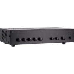
FRONT PANEL
SOURCE
MP3 PLAYER
AUX IN
PLAY/PAUSE BT PAIR
ON/OFF
ES
80W AUDIO SOURCE
MIXER AMPLIFIER
5 4
1
3
123
2
6 7 89
7
ENGLISH
1
Input 1 volume control.
2
Input 2 volume control.
3
MP3 player
9
and AUX INPUT
17
volume control.
4
MP3 button (with LED)
Press to turn on (the LED is lit) the MP3 player, which signal is sent to the internal
amplifier (and also MUSIC ON HOLD
20
and PRE OUT
19
outputs).
If activated, the AUX INPUT
17
on the rear panel will be muted (the AUX button LED
will turn off).
The MP3 Player signal is always senT To The MUsiC on holD
20
oUTPUT (ThaT is noT affeCTeD by The
volUMe ConTrol anD MP3 / aUX bUTTons).
5
AUX button (with LED)
Press to turn on (the LED is lit) the AUX INPUT
17
(on the rear panel), which signal is sent to
the internal amplier (and also PRE OUT
19
).
If activated, the internal MP3 player will be muted (the MP3 button LED will turn off).
6
Internal amplier MASTER volume control
noTe: The aUDio oUTPUTs having rCa ConneCTors (MUsiC on holD
20
anD Pre oUT
19
) are noT
affeCTeD by The MasTer volUMe ConTrol.
7
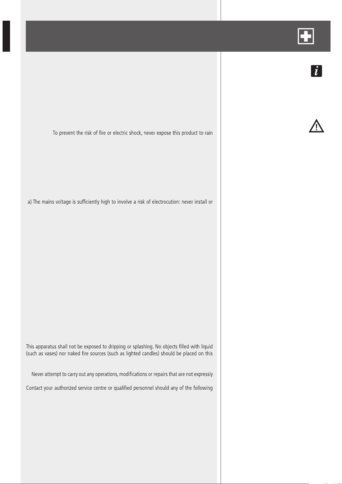
LEDs
ON green: the device is switched on
PROT red: overload protection
orange: thermal protection
PRIOR yellow: the input 1 and 2 priority function is enabled through the
dip-switch 3
21
noTe: iT Does noT inDiCaTe The PrioriTy aCTivaTion in Progress.
SIG/PK green: the signal level is higher than – 15 dB
green + red: the signal level is in the 0 ÷ +2 dB range
red (peak): the signal level is equal or higher than +3 dB
0 Db = signal level ThaT allows To geT The aMPlifier MaXiMUM Power.
The inTernal ‘liMiTer’ CirCUiT helPs To avoiD The aMPlifier overloaDing, yeT iT is aDvisable To reDUCe The
MasTer volUMe (or a single inPUT volUMe where a Too high signal is PresenT) when The sig/PK leD
is ConTinUoUsly inDiCaTing reD.
8
Main POWER switch (0 = off; I = on)
9
MP3 player with ‘Bluetooth’ (read the respective manual section).
123
i
i
i
i
8
ENGLISH
10
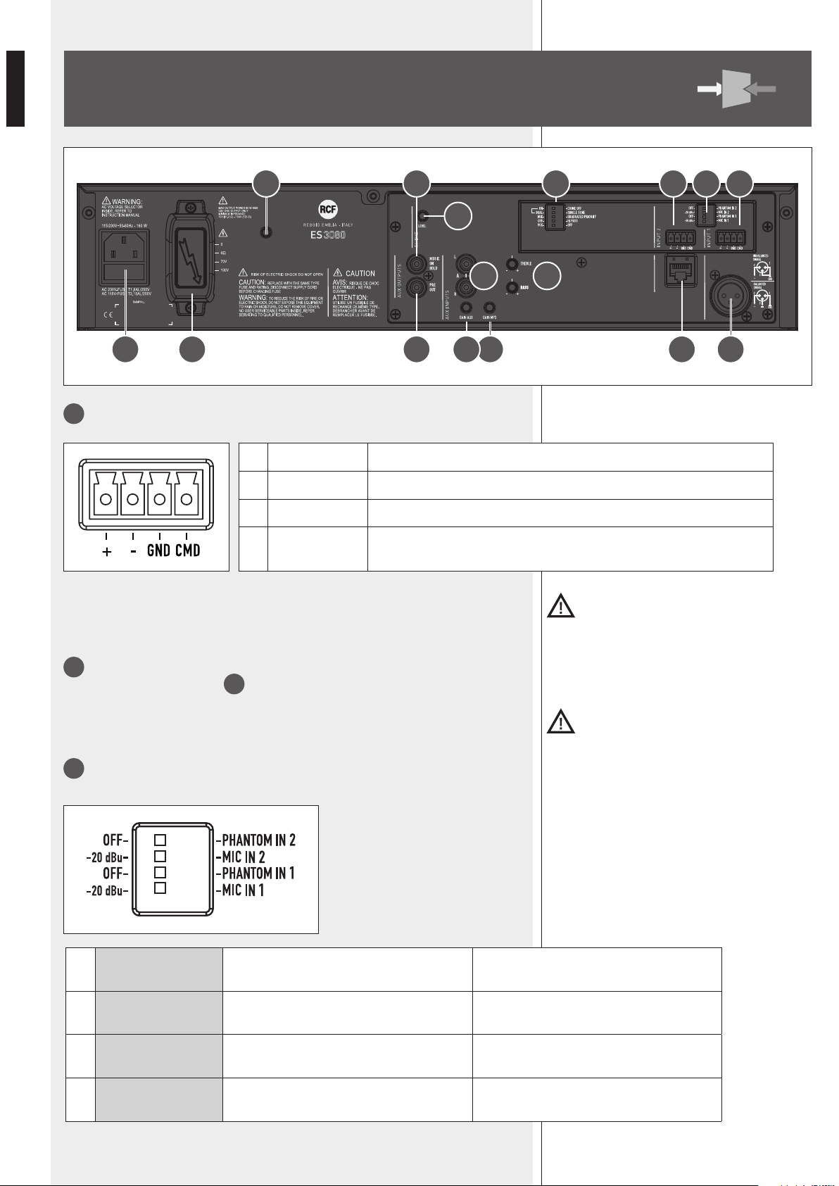
Balanced audio input 1 (removable connector).
Important: It Is necessary to eIther lInk the cmD pIn to grounD of the respectIve
removable connector or use the voX functIon to open the auDIo Input 1 (even when usIng
the Xlr plug for the auDIo sIgnal).
11
Balanced audio input 2 (removable connector).
See the ‘Balanced audio input 1’
10
.
Important: It Is necessary to eIther lInk the cmD pIn to grounD of the respectIve
removable connector or use the rJ 45 port prIorIty commanD to open the auDIo Input 2.
12
MIC-LINE input setting (inputs 1 and 2) through 4 dip-switches:
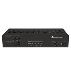
REAR PANEL
1 + Hot audio input
2 - Cold audio input
3 GND ground
4 CMD command: input on / priority access when connected to ground
1
OFF – PHANTOM
(IN 2)
OFF: input 2 phantom power is off.
PHANTOM 2:
input 2 phantom power is on.
2
-20 dBu – MIC
(IN 2)
-20 dBu:
input 2 sensitivity set to LINE (-20 dBu).
MIC 2:
input 2 sensitivity set to MIC.
3
OFF – PHANTOM
(IN 1)
OFF: input 1 phantom power is off.
PHANTOM 1:
input 1 phantom power is on.
4
-20 dBu – MIC
(IN 1)
-20 dBu:
input 1 sensitivity set to LINE (-20 dBu).
MIC 1:
input 1 sensitivity set to MIC.
A
Canovi
Manini
PL010775
ES 3080
15/05/14
1:1
15/05/14
UNI EN 22768-1
EN 22768-1
Manini
Canovi
A
Serigraa Frame
Frame Silk-Screen
Emissione documento/Production release
1
1
A termine di legge ci riserviamo la proprieta' di questo disegno con divieto di riproduzione e renderlo noto a terzi senza nostra autorizzazione scritta
ELETTROACUSTICHE
INDUSTRIE
QUOTE SENZA INDICAZIONE DI TOLLERANZA.
DIMENSIONS WITHOUT TOLLERANCE INDICATIONS.
GRADO DI PRECISIONE/ACCURACY
CODICE/PART NUMBER
MATRICOLA
OGGETTO MODIFICA/MODIFY OBJECT
CONTR.
CHECK
DISEGN.
DRAWN
DATA
DATE
N.
DISEGN.
DRAWN
CONTR.
CHECKED
DATA/DATE
Descrizione
Description
Materiale
Material
Tratt. TERMICO
HEAT treatment
Tratt. SUPERFICIALE
SURFACE treat.
FOGLIO/SHEET FOGLI/SHEETS
SCALA/SCALE
Vedi Note
See Notes
Vedi Note / See Notes
Vedi Note / See Notes
NOTES:
NOTE:
- Serigrafare colore BIANCO.
- Silk-screen printing color WHITE.
- Dimensioni Pannello
- Panel Dimension
430
86
80W AUDIO SOURCE
& MIXER AMPLIFIER
19 16 14 1323
25 20 21 11 1012
22
17 15
24 18
9
ENGLISH
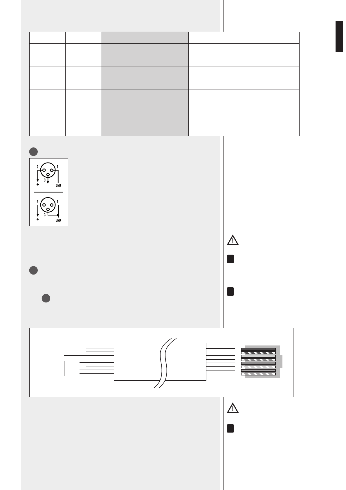
Examples of dip-switch settings:
DIP 1/3 DIP 2/4 MODE USE (EXAMPLES)
OFF – 20 dBu LINE Audio source having a – 20 dBu output
OFF MIC MIC Dynamic microphones
PHANTOM – 20 dBu LINE with PHANTOM BM 3001 paging microphone
PHANTOM MIC MIC with PHANTOM Electret microphones
13
Balanced audio input 1 (XLR socket)
Balanced connection + hot
– cold
GND ground
Unbalanced connection
Important: It Is necessary to eIther lInk the cmD pIn to grounD of the respectIve
removable connector or use the voX functIon to open the auDIo Input 1.
Do noT Use an UnbalanCeD ConneCTion when The ‘PhanToM’ Power sUPPly is swiTCheD on.
14
Balanced audio input 2 (RJ 45 port)
(for a BM 3001 paging microphone).
noTe: when a bM 3001 Paging MiCroPhone is ConneCTeD, iT is neCessary To seT The DiP-swiTChes 1
anD 2
12
To The ‘line wiTh PhanToM’ MoDe .
The bM 3001 Paging MiCroPhone shall be seT To ‘loCal’.
Cable with RJ 45 plug:
gnd
+
–
Priority
command
(to gnd)
Audio
signal
Green
Blue
Orange
Orange/White
Brown
Brown/White
Green
Blue/White
Blue
Green/White
Orange
Orange/White
12345678
RJ
Important: It Is necessary to use the rJ 45 port prIorIty commanD to open the auDIo Input
2. (for Instance, through the bm 3001 pagIng mIcrophone push-button).
alThoUgh eaCh MiC-line inPUT has 2 DifferenT ConneCTors, These CannoT be UseD To MiX DifferenT
signals; only one aUDio soUrCe Can be ConneCTeD.
i
i
i
10
ENGLISH
15
TREBLE and BASS controls for both the internal MP3 player and the AUX INPUT.
16
GAIN MP3: MP3 player gain control.
17
AUX INPUT with dual RCA connector.
The Two Channels of The sTereo soUrCe ConneCTeD To The aUX inPUT are sUMMeD inTernally (To geT
a Mono signal).
18
GAIN AUX: AUX INPUT gain control.
19
PRE OUT audio output (with RCA connector) that sends the same signal routed to
the internal amplier (signal that can be either a single source with priority or the mix of
all the inputs 1, 2, the internal MP3 player and the AUX INPUT).
Use Pre oUT To ConneCT aDDiTional eXTernal aMPlifiers.
20
MUSIC ON HOLD audio output (with RCA connector) that sends the internal MP3
audio signal (mono).
The MUsiC on holD oUTPUT is noT affeCTeD by any volUMe ConTrol nor seleCTor anD Can be
linKeD To a TelePhone sysTeM (in orDer To geT The ‘MUsiC on holD’ fUnCTion).
21
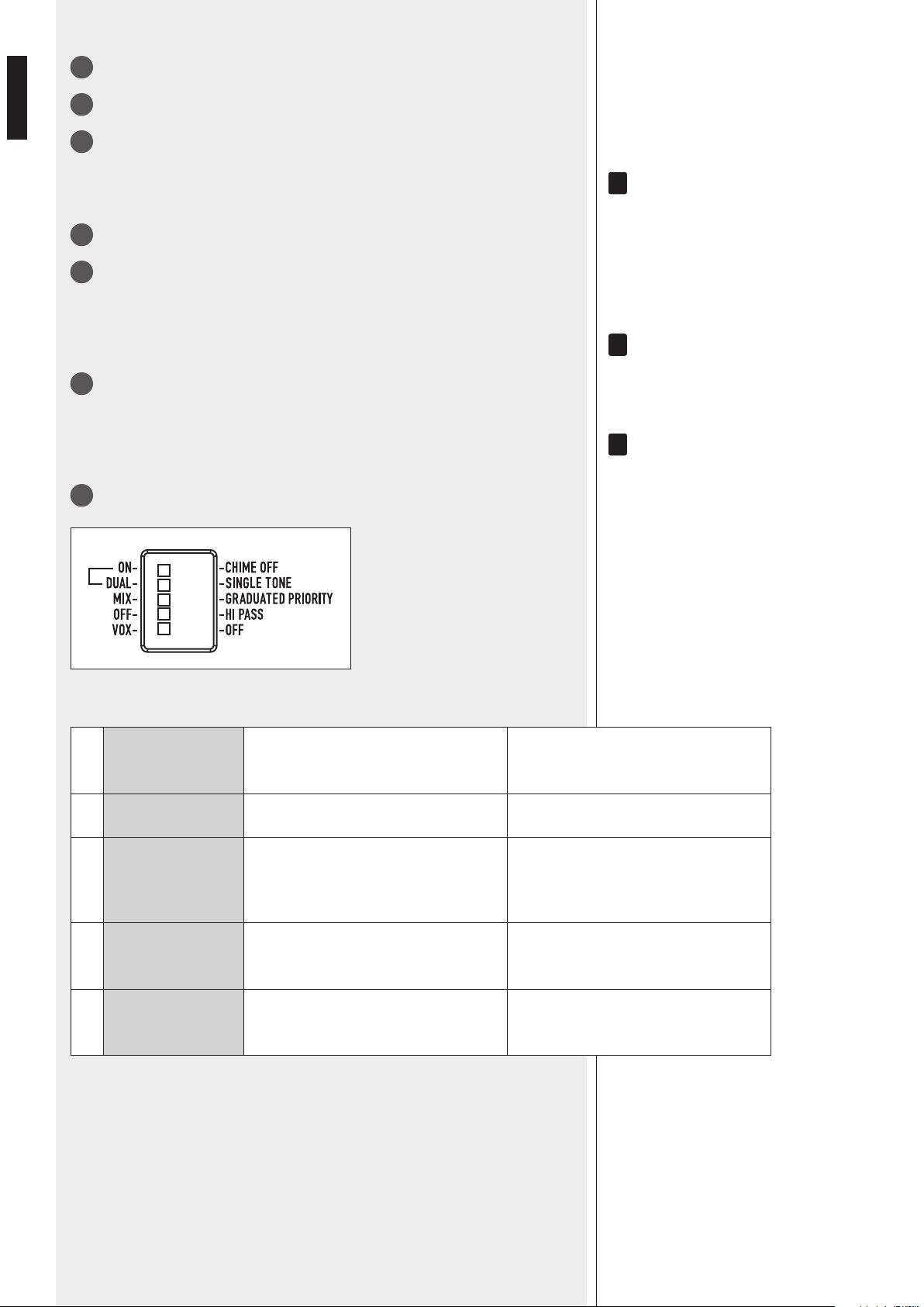
5 dip-switches for settings:
i
i
i
1 ON – CHIME OFF
ON: the chime is enabled and played
once immediately after a priority
command activation.
CHIME OFF: the chime is disabled.
2 DUAL – SINGLE TONE DUAL: two-tone chime. SINGLE TONE: single tone chime.
3 MIX – GR. PRIORITY
MIX: the priority function is disabled.
All inputs are mixed and sent to the
amplier (even if a priority command is
in progress).
GRADUATED PRIORITY:
graduated priority mode
(read the ‘Operation’ manual section ).
4 OFF – HI PASS
OFF: the audio high pass lters of the
inputs 1 and 2 are not inserted
(at frequency response).
HI PASS: the audio high pass lters of
the inputs 1 and 2 are inserted.
5 VOX – OFF
VOX: the input 1 VOX function is on (the
input 1 is automatically open when a
signal is detected on its input).
OFF: the input 1 VOX function is off.

11
ENGLISH
22
CHIME LEVEL (a trimmer adjustable by using a small screwdriver).
23
- 100 / 70 V constant voltage line
- Low impedance (min. 4 Ω).
Use 1 output only (read the section ‘Speaker connection’).
24
Mains connector with fuse
Before connecting the power cord, verify that the apparatus voltage (230 or 115 V ac)
corresponds to the available mains supply.
NOTE: THE FUSE TYPE IS MARKED ON THE REAR PANEL (BELOW THE MAINS CONNECTOR).
25
Antenna input (‘Bluetooth’).
MP3 PLAYER
SOURCE
MP3 PLAYER
AUX IN
PLAY/PAUSE BT PAIR
ON/OFF
ES
80W AUDIO SOURCE
MIXER AMPLIFIER
36
31 32 33 34 35
37 38
33
▐◄◄ button
While playing:
-
-
-
►►▌
34
button
While playing:
-
-
SOURCE: button: push to loop among different MP3 sources (SD CARD, USB and
AUX IN).
31
PLAY / PAUSE: button: push to start the playback (if stopped) or toggle play /
pause the current MP3file
32
12
ENGLISH
35
BT PAIR ON/OFF button with bicolour LED
- Push once (for an instant) to make it detectable (for about a minute) to the external
Bluetooth device.
- Push and hold (at least 3 seconds) to disable Bluetooth (the LED lights off); push and
hold (at least 2 second) to enable Bluetooth again.
LED INDICATION
OFF Bluetooth is disabled.
BLUE (2 seconds) / OFF (1 second) loop
Bluetooth is enabled, but the player is in stand-by, waiting for pairing to the
external device.
BLUE blinking every 2 seconds The player is connected to an external Bluetooth (A2DP) device.
BLUE steady lit
The player is connected to an external Bluetooth (A2DP) device and is currently
receiving streaming audio.
BLUE / RED
The player is currently detectable (for about a minute) by the external
Bluetooth device.
36
‘Secure Digital’ (SD) card port (max. 4 GB).
Do NOT insert an SD CARD if a USB flash-drive is already inserted into its respective
port
37
.
37
Port for a USB flash drive (max. 4 GB).
The insertion of a USB flash drive is automatically detected.
Do NOT insert a USB flash drive if an SD CARD is already inserted into its respective
port
36
.
N
OTES ABOUT USB FLASH DRIVES:
- FORMAT: FAT 12 / FAT 16 / FAT 32.
- F
ILE NAME: 32 BYTE / DIR. NAME: 32 BYTE / TAG NAME: 32 BYTE.
- USB 1.1 SUPPORT AND ALSO 2.0 (BUT AT THE SAME SPEED OF USB 1.1).
- A FEW USB FLASH DRIVE TYPES MAY NOT BE COMPATIBLE.
38
AUX IN (1/8” TRS jack): MP3 player aux input to connect (via cable) the audio output of an
external device.
disconnect the external Bluetooth device.
NOTE: DO NOT CONFUSE THIS INPUT WITH THE OTHER AUX INPUT
17
ON THE REAR PANEL.
INPUT / MEMORY SELECTION
The MP3 player automatically selects inputs / memories with different priority levels as
follows:
1. (highest priority) Bluetooth external device, if connected and sending streaming audio.
NOTES ABOUT MP3 FILES
- MP3: means MPEG Audio Layer 3 and refers to an audio compression type.
- This player reads MP3 files on USB flash drives and SD cards.
- The file extension must be .mp3.
- The max. directory (/ folder) level is 8, including the ‘root’.
- It is advisable to use MP3 files having a sampling frequency of 44.1 kHz and a
fixed bit-rate of at least 128 kbps (if higher, for instance 192 kbps, the sound
quality will be better).
- The player may not play MP3 files in the order as written on the USB flash drive
/ SD CARD.
2. When Bluetooth external device is playing and then disconnected, audio source
won’t do any switch automatically, and it will be needed to select the MP3 source with
SOURCE button.
3. When a MP3 source is playing and a Bluetooth device is connected, music will be
switched to BT.
13
ENGLISH
‘BLUETOOTH’ DEVICES
‘Bluetooth’ is a wireless technology standard for exchanging data over short distances
from xed and mobile devices (e.g. cellular phones).
The MP3 player includes a Bluetooth interface to receive audio signals from compatible
external devices, which must have A2DP technology (‘Advanced Audio Distribution
Prole’).
To connect your Bluetooth external device to the MP3 player:
1. Check if the antenna
25
on the rear panel is properly connected and oriented.
2. Enable ‘Bluetooth’ on the external device.
3. Push the MP3 player BT PAIR ON/OFF button
35
(its LED now ashes blue / red).
4. Within a minute, on the external device, start searching other devices with active
Bluetooth; ES3080 should be displayed.
5. Pair the external device and ES 3080.
6. Start the audio playback on the external device (which should be now included in
the available sources of the internal MP3 player).
When turning ES 3080 on, the MP3 player automatically tries to connect (via
‘Bluetooth’) to the last paired external device (if available).
AMPLIFIER OPERATION
‘voX’ is an inTernal CirCUiT ThaT aUToMaTiCally oPens The inPUT 1 anD TaKes PrioriTy (if enableD
ThroUgh The DiP-swiTCh 3
21
) when a signal is DeTeCTeD on iTs inPUT.
- ‘MIX’ mode
The priority function is disabled.
All signals (inputs 1-2, if open, and the MP3 player / AUX INPUT) are always present,
mixed together and sent to the internal amplier.
The inTernal MP3 Player / aUX inPUT volUMe DePenDs on The fronT Panel PrograM inPUTs
3
ConTrol anD also The resPeCTive gain ConTrol seTTings (on The rear Panel): gain MP3
16
,
gain aUX
18
.
- ‘GRADUATED PRIORITY’ mode
Audio inputs are managed according to graduated priority levels:
1. (highest) Input 1
2. Input 2
3. Either MP3 player or AUX INPUT.
If a priority command is present (or VOX), only the signal of the input with the highest
priority level is sent to the internal amplier (and PRE OUT), while the other inputs (with
lower priority level) are momentary muted (until the priority command is removed).
- RCF BM 3001 paging microphone (not included)
The input 2 has an RJ 45 port, to which a BM 3001 paging microphone can be
connected
(note: it is necessary to set the dip-switches 1 and 2
12
to the ‘LINE with PHANTOM’
mode).
The BM 3001 paging microphone shall be set to ‘LOCAL’.
i
i
14
ENGLISH
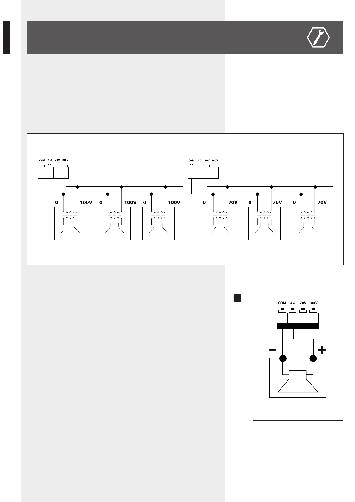
Use 1 output only, DO NOT MIX 100 / 70 V and 4 Ω CONNECTIONS !
100 / 70 V CONSTANT VOLTAGE OUTPUTS
- Each speaker shall have a line transformer with the input voltage equal to the line
voltage (100 / 70 V).
- The speaker total power shall not be higher than the amplier maximum power.
LOW IMPEDANCE OUTPUT (4 Ω)
- The speaker total impedance shall not be lower than 4 Ω.
noTe: a ToTal iMPeDanCe eqUal To 4 Ω allows The aMPlifier MaXiMUM Power Delivery. a higher
iMPeDanCe leaDs To a reDUCTion of The Power DelivereD by The aMPlifier (e.g. 8 Ω: aPProX. ½
Power, 16 Ω: aPProX. ¼ Power). an iMPeDanCe lower Than 4 Ω overloaDs The aMPlifier.
- Speaker models shall be chosen by considering the max. power (80 W) that the
amplier can deliver.
- Speaker line should be as short as possible; long cables may need large wire cross-
sections.
- Do not use, at the same time, both the low impedance output (4 Ω) and the
constant voltage output (100V or 70V), as this overloads the amplier.
SPEAKER CONNECTION
100 V 70 V
i

15
ENGLISH
POWER SUPPLY VOLTAGE CHANGE
IMPORTANT: This manual section concerns qualied personnel only.
The following instructions are to be ignored by users.
Make sure the device is not connected to the mains (unplug the power cord).
Remove the lid.
Find the 230 / 115 V voltage change connector (in the picture, it is highlighted by a square).
According to the PCB indication, if the mains voltage is 230 V, set the connector to the 230 V
position, if the mains voltage is 115 V, set the connector to the 115 V position.
Ret the device lid.
Before connecting the device to the mains, make sure that the fuse (inside the IEC power
supply connector of the rear panel) is the correct current rating for the mains voltages (read
the fuse indication below the connector).
16
ENGLISH
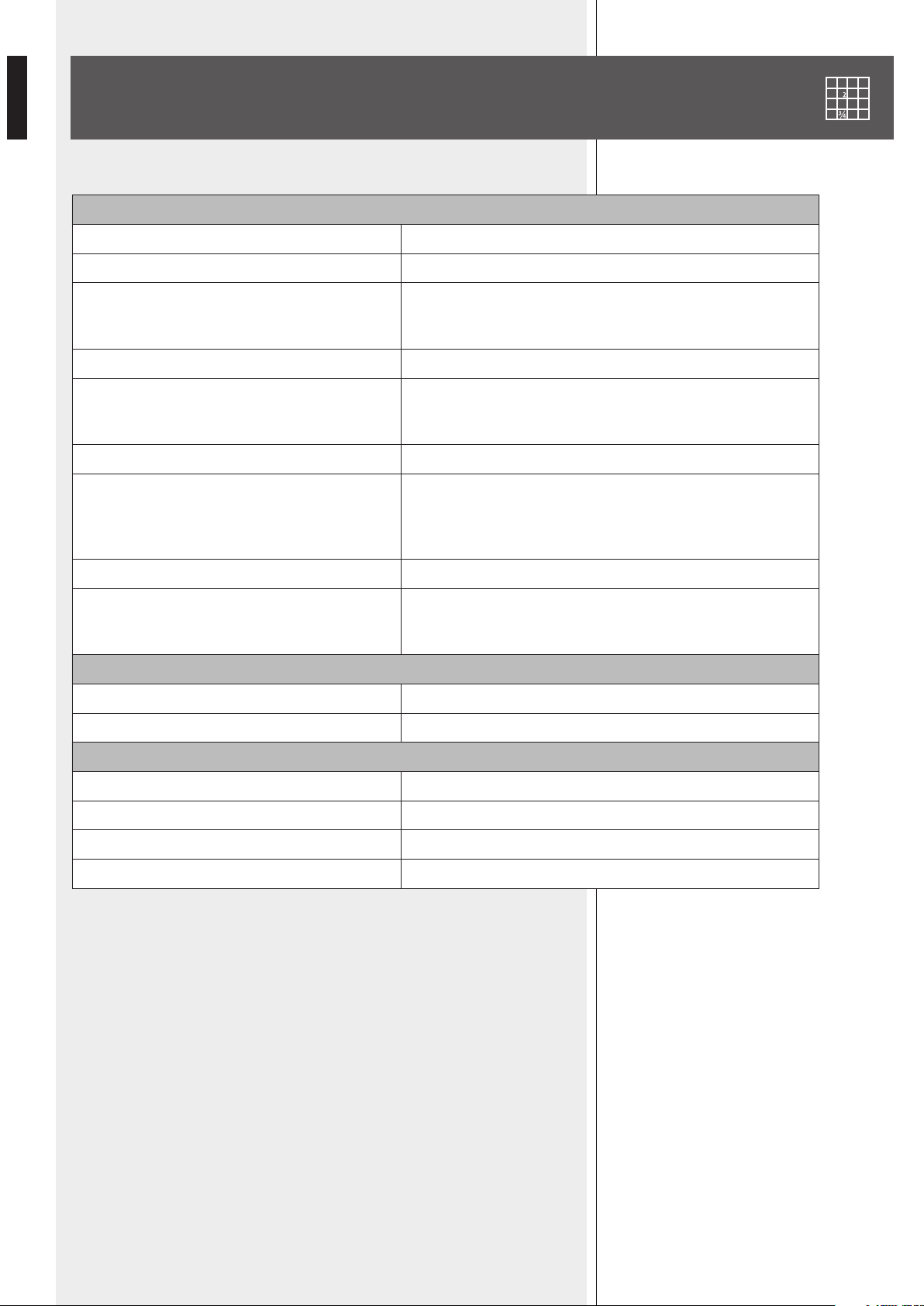
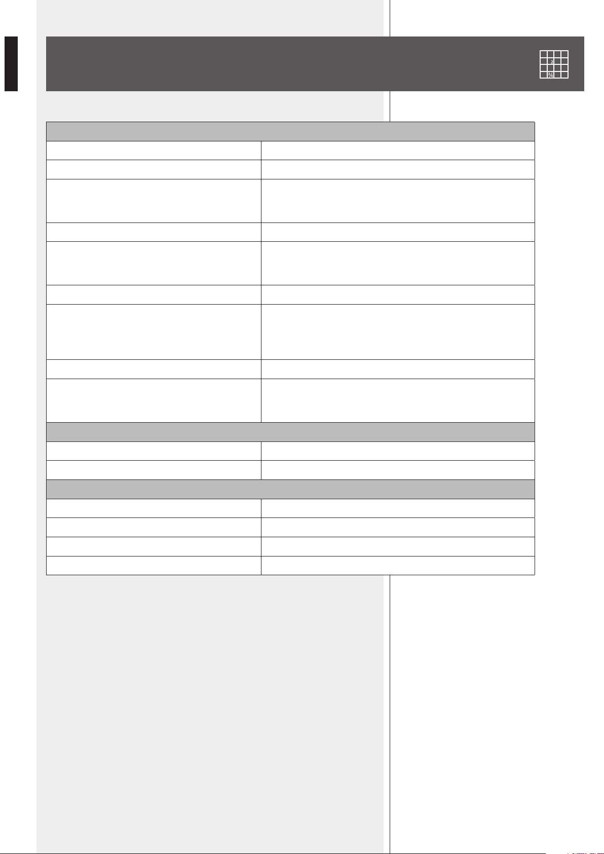
SPECIFICATIONS
AMPLIFIER
Output (RMS) power 80 W
Frequency response 50 Hz ÷ 16 kHz
Signal / noise ratio
- Inputs 1, 2
- AUX INPUT (rear panel)
60 dB
80 dB
Distortion (at 1 kHz, nominal power) < 0.3 %
MP3 / AUX INPUT tone controls
- Bass
- Treble
– 9 ÷ + 6 dB @ 100 Hz
– 14 ÷ + 8 dB @ 10 kHz
High-pass lter (inputs 1, 2) 150 Hz
Input sensitivity / impedance
- Inputs 1–2, MIC
- Inputs 1–2, LINE
- AUX INPUT (rear panel)
Balanced, – 62 dBu (max. – 25 dBu ) / 10 kΩ
Balanced, – 29 dBu (max. 0 dBu) / 10 kΩ
Adjustable – 18 ÷ + 20 dBu / 20 kΩ
‘Phantom power’ voltage / current 30 V / 18 mA
Speaker outputs
Low impedance
Constant voltage
4 Ω
70 V (63 Ω) / 100 V (125 Ω)
PROTECTIONS
Amplier Overload, short circuit, thermal
Power supply fuses
GENERIC
Operating voltage 115-230V / 50-60 Hz
Power (consumption) 160 W
Dimensions (w, h, d) 442 mm, 88 mm, 230 mm (2U 19” rack)
Net weight 3.9 kg
17
ENGLISH
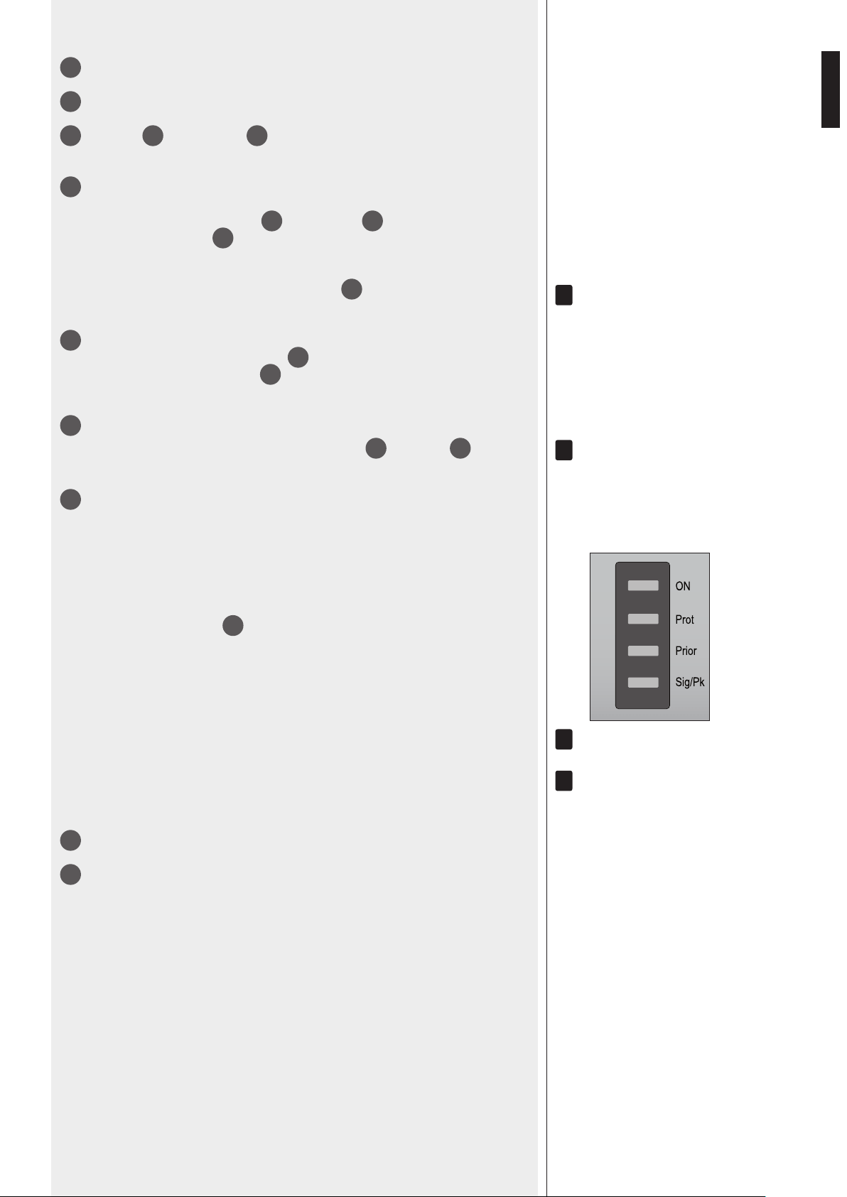
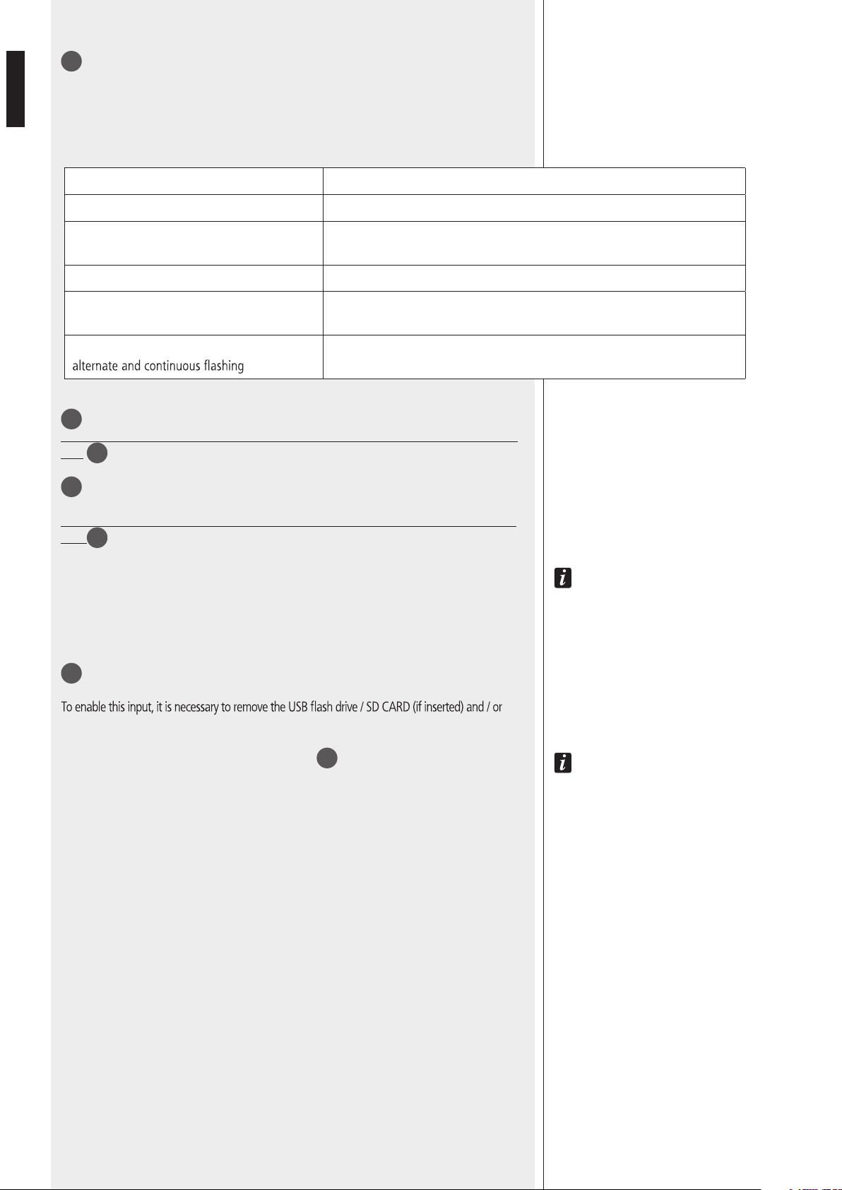
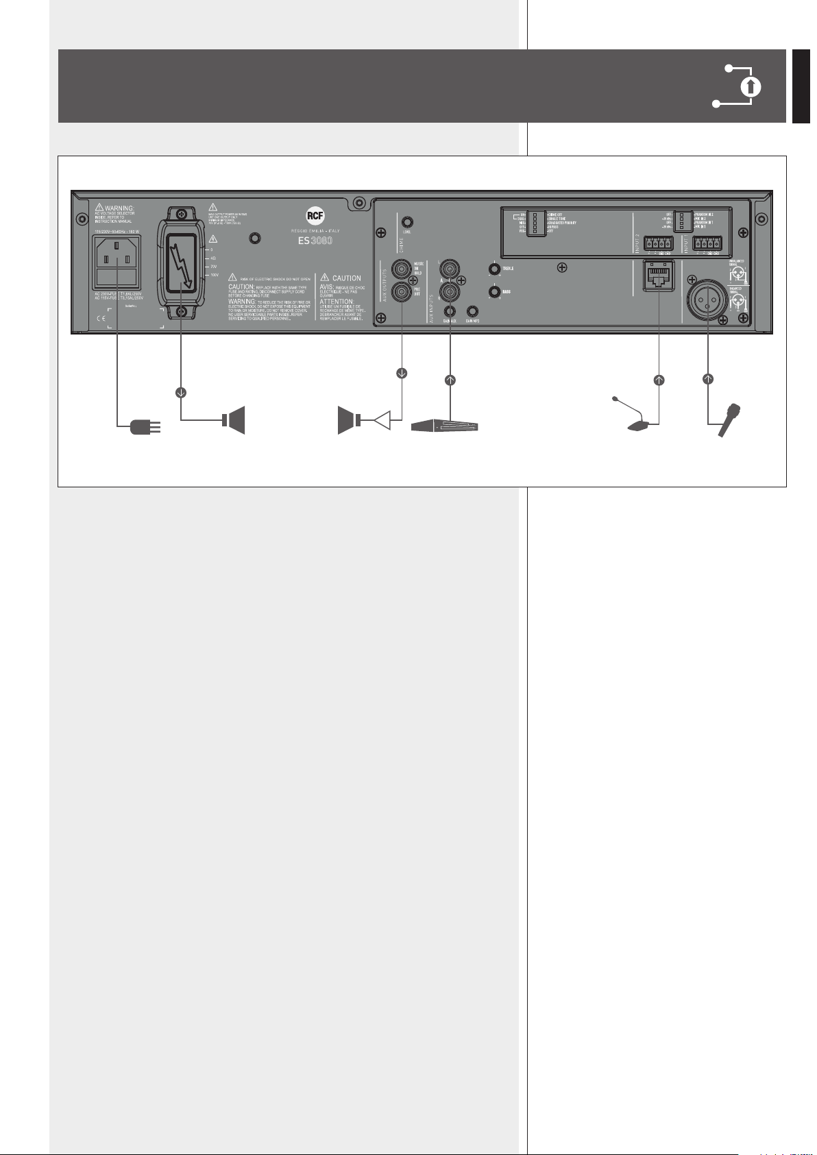
EXAMPLE OF CONNECTIONS
A
Canovi
Manini
PL010775
ES 3080
15/05/14
1:1
15/05/14
UNI EN 22768-1
EN 22768-1
Manini
Canovi
A
Serigraa Frame
Frame Silk-Screen
Emissione documento/Production release
1
1
A termine di legge ci riserviamo la proprieta' di questo disegno con divieto di riproduzione e renderlo noto a terzi senza nostra autorizzazione scritta
ELETTROACUSTICHE
INDUSTRIE
QUOTE SENZA INDICAZIONE DI TOLLERANZA.
DIMENSIONS WITHOUT TOLLERANCE INDICATIONS.
GRADO DI PRECISIONE/ACCURACY
CODICE/PART NUMBER
MATRICOLA
OGGETTO MODIFICA/MODIFY OBJECT
CONTR.
CHECK
DISEGN.
DRAWN
DATA
DATE
N.
DISEGN.
DRAWN
CONTR.
CHECKED
DATA/DATE
Descrizione
Description
Materiale
Material
Tratt. TERMICO
HEAT treatment
Tratt. SUPERFICIALE
SURFACE treat.
FOGLIO/SHEET FOGLI/SHEETS
SCALA/SCALE
Vedi Note
See Notes
Vedi Note / See Notes
Vedi Note / See Notes
NOTES:
NOTE:
- Serigrafare colore BIANCO.
- Silk-screen printing color WHITE.
- Dimensioni Pannello
- Panel Dimension
430
86
80W AUDIO SOURCE
& MIXER AMPLIFIER
RADIO/TUNER
BM 3001 MIC.
18
ITALIANO
IMPORTANTE
Prima di collegare ed utilizzare questo prodotto, leggere attentamente le istruzioni
contenute in questo manuale, il quale è da conservare per riferimenti futuri.
Il presente manuale costituisce parte integrante del prodotto e deve accompagnare
quest’ultimo anche nei passaggi di proprietà, per permettere al nuovo proprietario di
conoscere le modalità d’installazione e d’utilizzo e le avvertenze per la sicurezza.
L’installazione e l’utilizzo errati del prodotto esimono la RCF S.p.A. da ogni responsabilità.
ATTENZIONE:
questo prodotto alla pioggia o all’umidità.
AVVERTENZE PER LA SICUREZZA
1. Tutte le avvertenze, in particolare quelle relative alla sicurezza, devono essere lette con
particolare attenzione, in quanto contengono importanti informazioni.
2. ALIMENTAZIONE DIRETTA DA RETE
costituire un rischio di folgorazione per le persone: non procedere mai all’installazione
o connessione dell’apparecchio con l’alimentazione inserita.
b) Prima di alimentare questo prodotto, assicurarsi che tutte le connessioni siano corrette
e che la tensione della vostra rete di alimentazione corrisponda quella di targa
dell’apparecchio, in caso contrario rivolgetevi ad un rivenditore RCF.
c) Le parti metalliche dell’apparecchio sono collegate a terra tramite il cavo di alimentazione.
Un apparecchio avente costruzione di CLASSE I deve essere connesso alla presa di rete
con un collegamento alla terra di protezione.
d) Accertarsi che il cavo di alimentazione dell’apparecchio non possa essere calpestato o
e) Per evitare il rischio di shock elettrici, non aprire mai l’apparecchio: all’interno non vi
sono parti che possono essere utilizzate dall’utente.
La presa di alimentazione a vaschetta posto sul retro dell’apparato è il dispositivo di
disconnessione dalla rete di alimentazione; tale dispositivo DEVE rimanere facilmente
accessibile dopo l’installazione e durante l’utilizzo dell’apparato.
IMPORTANTE
3. Impedire che oggetti o liquidi entrino all’interno del prodotto, perché potrebbero
causare un corto circuito. L’apparecchio non deve essere esposto a stillicidio o a spruzzi
(es. candele accese) deve essere posto sull’apparecchio.
4.
espressamente descritte sul manuale d’uso.
- l’apparecchio non funziona (o funziona in modo anomalo);
- il cavo di alimentazione ha subito gravi danni;
- oggetti o liquidi sono entrati nell’apparecchio;
- l’apparecchio ha subito forti urti.
5. Qualora questo prodotto non sia utilizzato per lunghi periodi, scollegare il cavo
d’alimentazione.
6. Nel caso che dal prodotto provengano odori anomali o fumo, spegnerlo
immediatamente e scollegare il cavo d’alimentazione.
ATTENZIONE
AVVERTENZE PER LA SICUREZZA

19
ITALIANO
7. I terminali marcati con il simbolo sono da ritenersi ATTIVI e PERICOLOSI ed il
loro collegamento deve essere effettuato da PERSONE ADDESTRATE oppure si devono
utilizzare cavi già pronti.
8. Non collegare a questo prodotto altri apparecchi e accessori non previsti.
Quando è prevista l’installazione sospesa, utilizzare solamente gli appositi punti di
ancoraggio e non cercare di appendere questo prodotto tramite elementi non idonei o
previsti allo scopo.
Vericare inoltre l’idoneità del supporto (parete, softto, struttura ecc., al quale è
ancorato il prodotto) e dei componenti utilizzati per il ssaggio (tasselli, viti, staffe non
fornite da RCF ecc.) che devono garantire la sicurezza dell’impianto / installazione nel
tempo, anche considerando, ad esempio, vibrazioni meccaniche normalmente generate da
un trasduttore.
Per evitare il pericolo di cadute, non sovrapporre fra loro più unità di questo prodotto,
quando questa possibilità non è espressamente contemplata dal manuale d’uso.
9. La RCF S.p.A. raccomanda vivamente che l’installazione di questo prodotto
sia eseguita solamente da installatori professionali qualicati (oppure da
ditte specializzate) in grado di farla correttamente e certicarla in accordo
con le normative vigenti.
Tutto il sistema audio dovrà essere in conformità con le norme e le leggi
vigenti in materia di impianti elettrici.
10. Sostegni e Carrelli
Se previsto, il prodotto va utilizzato solo su carrelli o sostegni consigliati dal produttore.
L’insieme apparecchio-sostegno / carrello va mosso con estrema cura. Arresti improvvisi,
spinte eccessive e superci irregolari o inclinate possono provocare il ribaltamento
dell’assieme.
11. Si devono considerare anche i fattori meccanici ed elettrici quando si installa un
sistema audio professionale (oltre a quelli prettamente acustici, come la pressione sonora,
gli angoli di copertura, la risposta in frequenza, ecc.).
12. Perdita dell’udito
L’esposizione ad elevati livelli sonori può provocare la perdita permanente dell’udito.
Il livello di pressione acustica pericolosa per l’udito varia sensibilmente da persona
a persona e dipende dalla durata dell’esposizione. Per evitare un’esposizione
potenzialmente pericolosa ad elevati livelli di pressione acustica, è necessario che
chiunque sia sottoposto a tali livelli utilizzi delle adeguate protezioni; quando si fa
funzionare un trasduttore in grado di produrre elevati livelli sonori è necessario indossare
dei tappi per orecchie o delle cufe protettive.
Consultare i dati tecnici contenuti nei manuali d’uso per conoscere le massime pressioni
sonore che i diffusori acustici sono in grado di produrre.
13. Non ostruire le griglie di ventilazione dell’unità. Collocare il prodotto lontano da fonti
di calore e garantire la circolazione dell’aria in corrispondenza delle griglie di aerazione.
14. Non sovraccaricare questo prodotto; vericare che non vi sia un cortocircuito
all’uscita dell’amplicatore.
15. Non forzare mai gli organi di comando (tasti, manopole ecc.).
16. Non usare solventi, alcool, benzina o altre sostanze volatili per la pulitura delle parti
esterne dell’unità; usare un panno asciutto.
NOTE SUI CAVI PER SEGNALI AUDIO
Per evitare fenomeni di rumorosità indotta sui cavi che trasportano segnali dai microfoni
o di linea (per esempio 0 dB), usare solo cavi schermati ed evitare di posarli nelle
vicinanze di:
- apparecchiature che producono campi elettromagnetici di forte intensità;
- cavi di rete;
- linee che alimentano altoparlanti.
20
ITALIANO
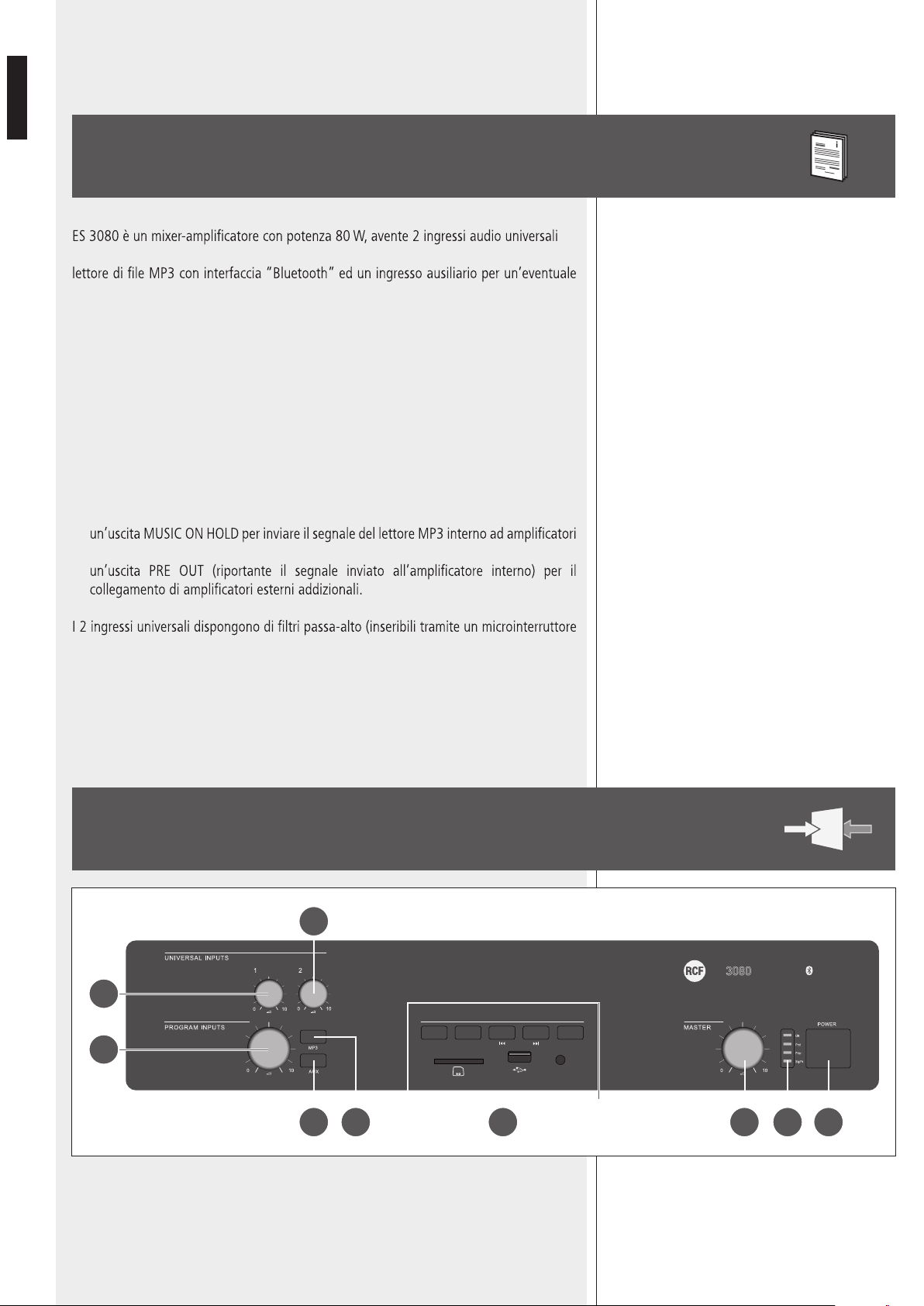
DESCRIZIONE
(mic.- linea) su connettori rimovibili (l’ingresso 1 dispone inoltre di connettore XLR), un
sorgente sonora esterna (es. lettore CD, sintonizzatore radio, ecc.).
L’ingresso 2 ha inoltre un connettore RJ 45 per la rapida connessione di una base
microfonica dedicata BM 3001 (utilizzando cavo CAT5).
L’uscita per diffusori acustici è disponibile sia a bassa impedenza (min. 4 Ω) oppure a
tensione costante 100 – 70 V (per diffusori con trasformatore).
Un circuito di rilevazione del segnale (“VOX”) con funzione di attivazione della priorità è
presente sull’ingresso 1.
Gli ingressi 1 e 2 possono ottenere la priorità (se abilitata) tramite un comando esterno
(collegato al connettore rimovibile od alla porta RJ 45).
Sono presenti:
-
addizionali oppure ad una centrale telefonica (come musica d’attesa);
-
comune) utili per migliorare l’intelligibilità della voce; l’ingresso ausiliario AUX INPUT ed il
lettore MP3 hanno i controlli di tono.
Sono presenti indicatori luminosi relativi allo stato dell’apparecchio (ON, PROT),
all’abilitazione del circuito di priorità (PRIOR) ed al livello del segnale audio (SIG/PK).
RCF S.P.A. VI RINGRAZIA PER L’ACQUISTO DI QUESTO PRODOTTO, REALIZZATO
IN MODO DA GARANTIRNE L’AFFIDABILITÀ E PRESTAZIONI ELEVATE.
PANNELLO
FRONTALE
SOURCE
MP3 PLAYER
AUX IN
PLAY/PAUSE BT PAIR
ON/OFF
ES
80W AUDIO SOURCE
MIXER AMPLIFIER
5 4
1
3
123
2
6 7 89

21
ITALIANO
1
Controllo del volume dell'ingresso audio 1.
2
Controllo del volume dell'ingresso audio 2.
3
Controllo di volume del lettore MP3
9
oppure dell'ingresso ausiliario AUX INPUT
17
.
4
Pulsante MP3 (con LED)
Seleziona (LED acceso) il lettore MP3, il cui segnale è inviato all'amplicatore interno (ed
anche all'uscita PRE OUT
19
).
La sua attivazione esclude automaticamente l'ingresso ausiliario AUX INPUT
17
sul retro
(l'indicatore luminoso del pulsante AUX si spegne).
il segnale Del leTTore MP3 è seMPre riPorTaTo sUll'UsCiTa MUsiC on holD
20
(non soggeTTa al
ConTrollo Di volUMe e Dei PUlsanTi MP3 e aUX).
5
Pulsante AUX (con LED)
Attiva (LED acceso) l'ingresso ausiliario AUX INPUT
17
verso l'amplicatore interno (ed
anche l'uscita PRE OUT
19
).
La sua attivazione esclude automaticamente il lettore MP3 (l'indicatore luminoso del
pulsante MP3 si spegne).
6
Controllo di volume principale MASTER dell'amplicatore interno.
noTa: le UsCiTe sU ConneTTori rCa (MUsiC on holD
20
e Pre oUT
19
) non sono soggeTTe a
qUesTo ConTrollo.
7
Indicatori luminosi (LED)
ON verde: l’apparecchio è acceso
PROT rosso: l’apparecchio è in protezione per sovraccarico
arancio: l’apparecchio è in protezione per riscaldamento eccessivo
PRIOR giallo: indica l’abilitazione della funzione di priorità degli ingressi 1 e 2
tramite il dip-switch 3 (vedi punto
21
);
noTa: non inDiCa l’aTTivazione in Corso Della PrioriTà.
SIG/PK verde: il livello del segnale audio è superiore ad almeno -15 dB
verde + rosso: il livello del segnale audio è compreso tra 0 e +2 dB
rosso (picco): il livello del segnale audio è uguale o superiore a +3 dB
0 Db = livello Del segnale Che PerMeTTe Di oTTenere la MassiMa PoTenza erogaTa Dall'aMPlifiCaTore.
il CirCUiTo “liMiTer” inTerno eviTa il sUPeraMenTo Della PoTenza MassiMa Dell'aMPlifiCaTore, TUTTavia è
Consigliabile abbassare il volUMe MasTer (oPPUre il singolo volUMe Di Un segnale eCCessivo) qUanDo
il leD sig/PK è CosTanTeMenTe rosso.
8
Interruttore principale dell'apparecchio POWER (0 = spento; I = acceso)
9
Lettore di le MP3 con interfaccia “Bluetooth” (vedere la rispettiva sezione del
manuale).
123
i
i
i
i
22
ITALIANO
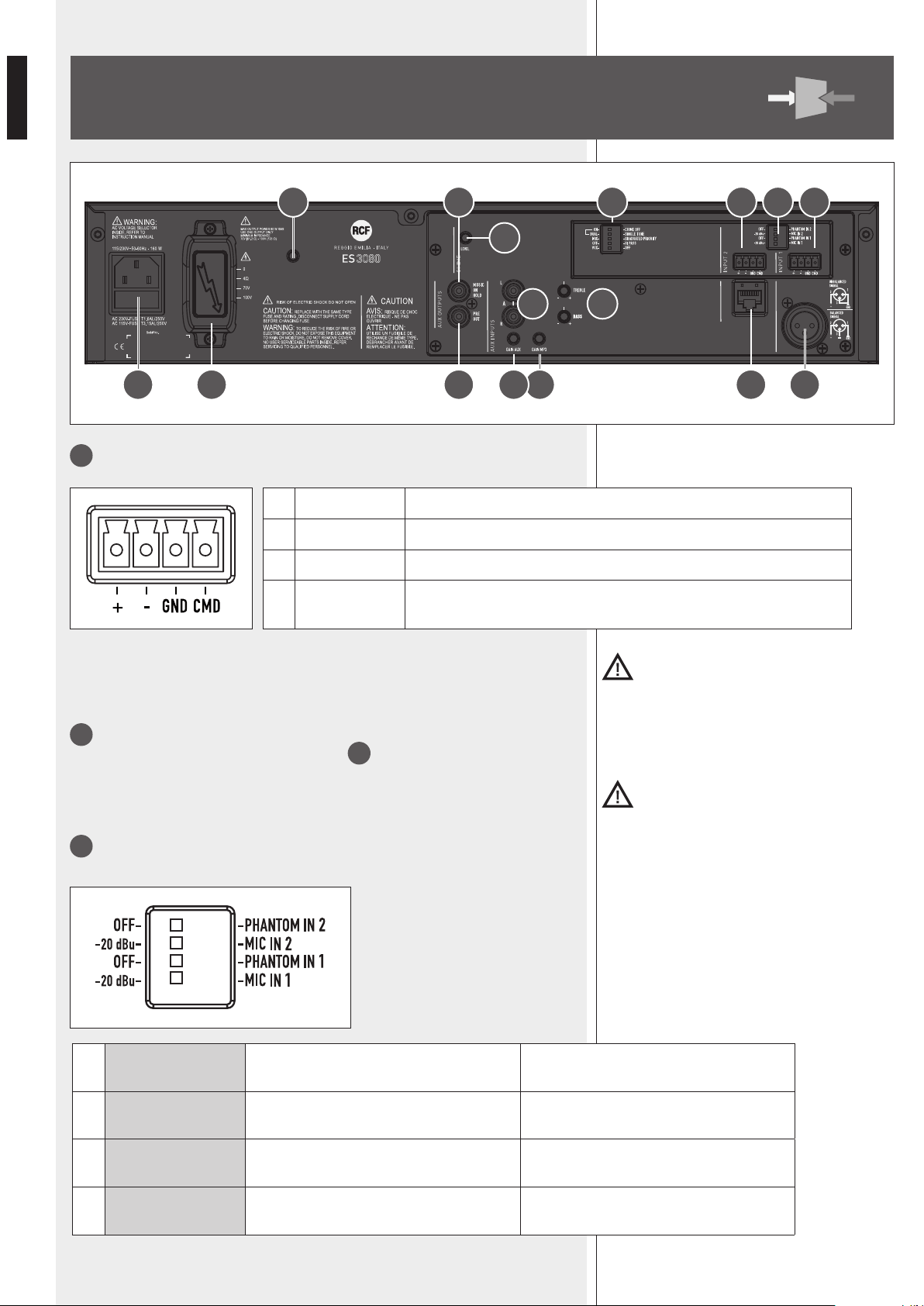
10
Ingresso audio 1 (connettore rimovibile):
Importante: per attIvare l'Ingresso 1, è necessarIo connettere a massa (gnD) Il contatto
cmD Del relatIvo connettore rImovIbIle (anche nel caso che sI utIlIzzI Il connettore Xlr
per Il segnale auDIo) oppure usare la funzIone voX.
11
Ingresso audio 2 (connettore rimovibile)
Per il collegamento, riferirsi l'ingresso audio 1
10
.
Importante: per attIvare l'Ingresso 2, è necessarIo connettere a massa (gnD) Il contatto
cmD Del relatIvo connettore rImovIbIle (oppure quello Della porta rJ 45).
12
Impostazioni dei 2 ingressi audio universali tramite 4 microinterruttori “dip-switch”:
PANNELLO
POSTERIORE
1 + Ingresso audio positivo
2 - Ingresso audio negativo
3 GND massa
4 CMD
comando per ottenere l’attivazione dell’ingresso e la priorità, quando
connesso a massa (GND)
1
OFF – PHANTOM
(IN 2)
OFF: l’alimentazione “phantom” è
disattivata all’ingresso audio 2.
PHANTOM 2: l’alimentazione “phantom”
è presente all’ingresso audio 2.
2
-20 dBu – MIC
(IN 2)
-20 dBu: ingresso audio 2 con sensibilità a
livello “linea” (-20 dBu).
MIC 2: ingresso audio 2 con sensibilità a
livello microfonico (basso).
3
OFF – PHANTOM
(IN 1)
OFF: l’alimentazione “phantom” è
disattivata all’ingresso audio 1.
PHANTOM 1: l’alimentazione “phantom”
è presente all’ingresso audio 1.
4
-20 dBu – MIC
(IN 1)
-20 dBu: ingresso audio 1 con sensibilità a
livello “linea” (-20 dBu).
MIC 1: ingresso audio 1 con sensibilità a
livello microfonico (basso).
A
Canovi
Manini
PL010775
ES 3080
15/05/14
1:1
15/05/14
UNI EN 22768-1
EN 22768-1
Manini
Canovi
A
Serigraa Frame
Frame Silk-Screen
Emissione documento/Production release
1
1
A termine di legge ci riserviamo la proprieta' di questo disegno con divieto di riproduzione e renderlo noto a terzi senza nostra autorizzazione scritta
ELETTROACUSTICHE
INDUSTRIE
QUOTE SENZA INDICAZIONE DI TOLLERANZA.
DIMENSIONS WITHOUT TOLLERANCE INDICATIONS.
GRADO DI PRECISIONE/ACCURACY
CODICE/PART NUMBER
MATRICOLA
OGGETTO MODIFICA/MODIFY OBJECT
CONTR.
CHECK
DISEGN.
DRAWN
DATA
DATE
N.
DISEGN.
DRAWN
CONTR.
CHECKED
DATA/DATE
Descrizione
Description
Materiale
Material
Tratt. TERMICO
HEAT treatment
Tratt. SUPERFICIALE
SURFACE treat.
FOGLIO/SHEET FOGLI/SHEETS
SCALA/SCALE
Vedi Note
See Notes
Vedi Note / See Notes
Vedi Note / See Notes
NOTES:
NOTE:
- Serigrafare colore BIANCO.
- Silk-screen printing color WHITE.
- Dimensioni Pannello
- Panel Dimension
430
86
80W AUDIO SOURCE
& MIXER AMPLIFIER
19 16 14 1323
25 20 21 11 1012
22
17 15
24 18

23
ITALIANO
Esempi di utilizzo dei microinterruttori:
DIP 1/3 DIP 2/4 MODO ESEMPI DI POSSIBILI COLLEGAMENTI
OFF – 20 dBu LIVELLO LINEA Sorgente audio con uscita a livello – 20 dBu
OFF MIC LIVELLO MICROFONICO Microfono dinamico
PHANTOM – 20 dBu LIVELLO LINEA con PHANTOM Base microfonica BM 3001
PHANTOM MIC LIVELLO MIC. con PHANTOM Microfono ad elettrete
13
Ingresso audio 1 (connettore XLR):
Collegamento bilanciato + polo positivo
– polo negativo
GND massa
Collegamento sbilanciato
Importante: per attIvare l'Ingresso 1, è necessarIo connettere a massa (gnD) Il contatto
cmD Del relatIvo connettore rImovIbIle oppure usare la funzIone voX.
non UTilizzare il CollegaMenTo sbilanCiaTo qUanDo l'aliMenTazione “PhanToM” è aTTiva.
14
Ingresso audio 2 (connettore RJ 45, utilizzabile per il collegamento di una base
microfonica RCF BM 3001).
noTa: nel Caso sia UTilizzaTa Una base MiCrofoniCa bM 3001, è neCessario iMPosTare il MoDo
“livello linea Con PhanToM” TraMiTe i MiCroinTerrUTTori 1 e 2
12
.
la base MiCrofoniCa bM 3001 Dovrà essere iMPosTaTa sU “loCal”.
Cavo con connettore RJ 45:
massa
+
–
Comando
(verso massa)
per priorità
Segnale
audio
verde
Blu
Arancio
Biancoarancio
Marrone
Biancomarrone
Verde
Biancoblù
Blu
Biancoverde
Arancio
Biancoarancio
12345678
RJ
Importante: per attIvare la porta rJ 45, è necessarIo porre a massa Il comanDo per la
prIorItà (aD esempIo, tramIte Il pulsante Della base mIcrofonIca bm 3001).
anChe se CiasCUn ingresso aUDio Universale DisPone Di 2 ConneTTori Diversi, non è Possibile
MisCelare insieMe 2 segnali Diversi; si PUò Collegare Una sola sorgenTe aUDio.
i
i
i
24
ITALIANO
15
Controlli di tono TREBLE (alti) e BASS (bassi) comuni all'ingresso AUX ed al lettore MP3.
16
Controllo di guadagno GAIN MP3 del lettore MP3.
17
Ingresso audio ausiliario AUX INPUT con doppio connettore RCA.
i DUe Canali Del segnale sTereo PresenTe all'ingresso aUX inPUT sono soMMaTi in Mono all'inTerno
Dell'aPPareCChio.
18
Controllo di guadagno GAIN AUX dell'ingresso ausiliario AUX INPUT.
19
Uscita audio (con connettore RCA) PRE OUT, riportante lo stesso segnale inviato
all'amplicatore di potenza interno (segnale che può essere un evento prioritario oppure la
miscelazione dei canali 1, 2, del lettore MP3 e dell'ingresso audio ausiliare AUX INPUT).
l'UsCiTa Pre oUT è UTile al fine Di Collegare Una o Più UniTà Di PoTenza esTerne aDDizionali.
20
Uscita audio (con connettore RCA) MUSIC ON HOLD, riportante l'uscita del lettore MP3
interno.
l'UsCiTa MUsiC on holD non è soggeTTa aD alCUn ConTrollo Di volUMe o seleTTore e PUò essere
CollegaTa aD Una CenTrale TelefoniCa in MoDo Da oTTenere la “MUsiCa D'aTTesa”.
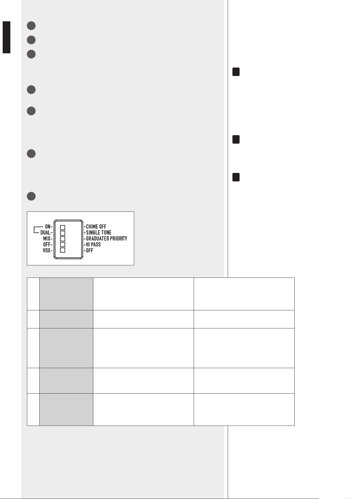
21
5 microinterruttori “dip-switch” per le impostazioni generiche:
i
i
i
1 ON – CHIME OFF
ON: abilitazione del suono di preavviso,
che è riprodotto una sola volta
immediatamente dopo l’attivazione di
un comando di priorità.
CHIME OFF:
disabilitazione del suono di preavviso.
2 DUAL – SINGLE TONE DUAL: il suono di preavviso è bitonale.
SINGLE TONE:
il suono di preavviso ha un solo tono.
3 MIX – GR. PRIORITY
MIX: disabilitazione della funzione di
priorità; tutti gli ingressi sono presenti
in miscelazione nel segnale inviato
all’amplicatore (anche se è presente un
comando di priorità).
GRADUATED PRIORITY: impostazione
del modo di priorità scalare
(vedere la sezione “funzionamento”).
4 OFF – HI PASS
OFF: i ltri passa-alto degli ingressi
audio 1 e 2 sono disinseriti
(risposta in frequenza lineare).
HI PASS: i ltri passa-alto degli ingressi
audio 1 e 2 sono inseriti.
5 VOX – OFF
VOX: attivazione della funzione “VOX”
(attivazione automatica dell’ingresso
audio 1 quando è rilevato un segnale al
suo ingresso).
OFF: disattivazione della funzione
“VOX”dell’ingresso audio 1.
25
ITALIANO
22
Controllo (trimmer regolabile tramite un piccolo cacciavite) CHIME LEVEL del volume
del suono di preavviso.
23
Uscite di potenza (max. 80 W) per i diffusori:
- a tensione costante 100 / 70 V;
- a bassa impedenza 4 Ω.
Utilizzare una sola uscita e vedere la sezione “Collegamento dei diffusori acustici”.
24
Connettore con fusibile per l'alimentazione principale da rete.
impostata (230 o 115 V) nell'apparecchio.
NOTA: IL TIPO DI FUSIBILE DA UTILIZZARSI È SPECIFICATO SUL PANNELLO POSTERIORE (SOTTO IL CONNETTORE).
25
Punto di collegamento dell'antenna per la connessione “Bluetooth”.
LETTORE MP3
SOURCE
MP3 PLAYER
AUX IN
PLAY/PAUSE BT PAIR
ON/OFF
ES
80W AUDIO SOURCE
MIXER AMPLIFIER
36
31 32 33 34 35
37 38
31
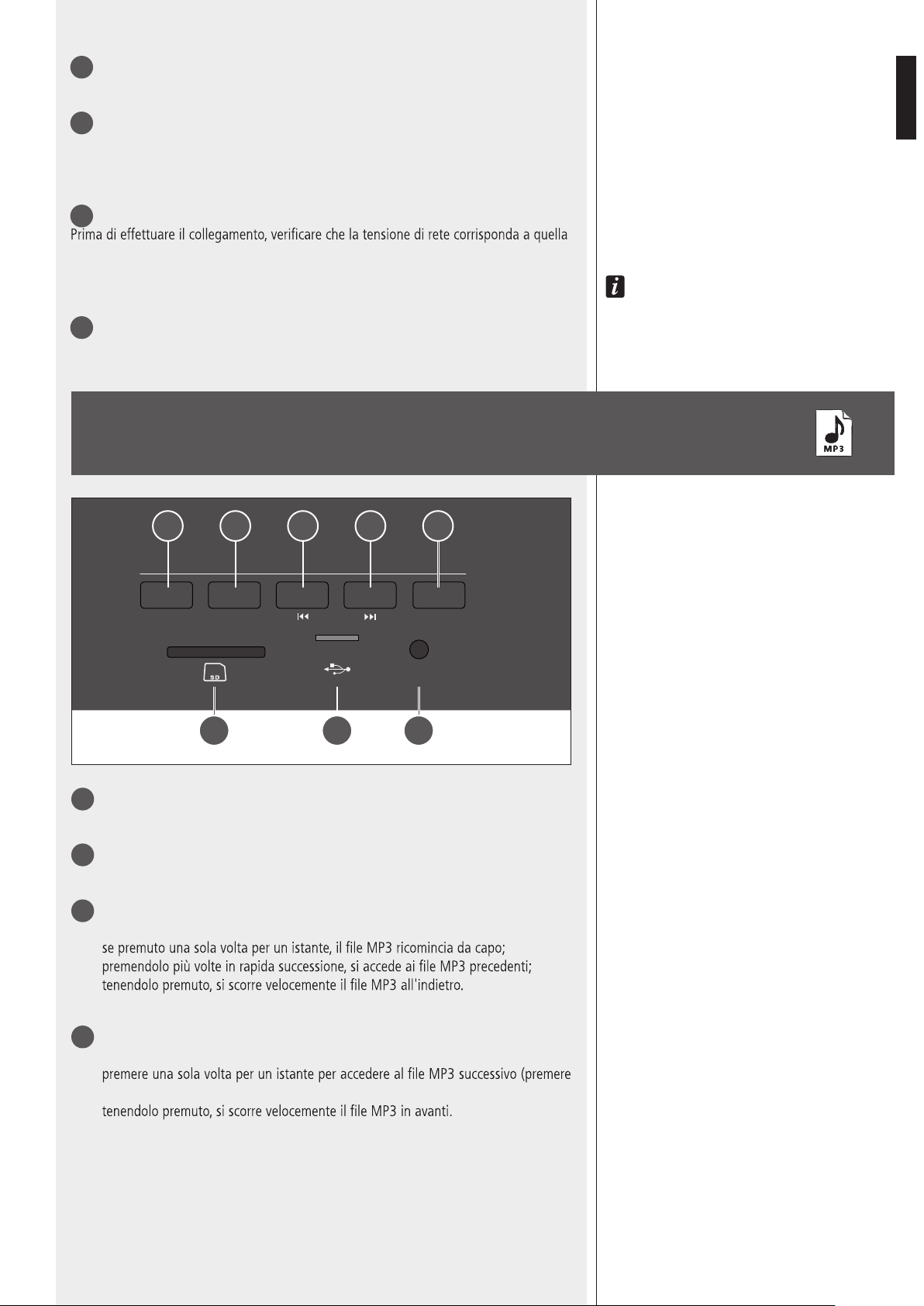
Pulsante SOURCE: seleziona la sorgente MP3 tra SD CARD, USB e AUX IN.
32
Pulsante PLAY/PAUSE: avvia e mette in pausa la riproduzione del brano MP3.
33
Pulsante ▐◄◄
Durante la riproduzione:
-
-
-
34
Pulsante ►►▌
Durante la riproduzione:
-
più volte per selezionare);
-
26
ITALIANO
35
Pulsante BT PAIR ON/OFF con LED bicolore
- Premere una sola volta per un istante per rendere individuabile (per circa un minuto) il
lettore dal dispositivo esterno “Bluetooth”.
- Se tenuto premuto (per almeno 3 secondi), si ha la disattivazione dell'interfaccia
“Bluetooth” (il LED del tasto si spegne); per riattivarla occorre tenerlo premuto per
almeno 2 secondi.
INDICAZIONE DEL LED
SPENTO Bluetooth disabilitato
BLU (2 secondi) / SPENTO (1 secondo), ciclico
Bluetooth abilitato, ma il lettore è in attesa di collegarsi ad un dispositivo
esterno.
Lampeggio BLU ogni 2 secondi Il lettore è collegato ad un dispositivo esterno tramite Bluetooth (A2DP).
BLU sempre acceso
Il lettore è collegato ad un dispositivo esterno tramite Bluetooth (A2DP) e sta
ricevendo i dati relativi al segnale audio (“streaming”).
Lampeggio BLU / ROSSO alternato e continuo Il lettore è rilevabile (per circa un minuto) dal dispositivo esterno Bluetooth.
36
Porta per l'inserimento di una scheda di memoria “Secure Digital” SD CARD
(max. 4 GB).
Non inserire una scheda SD CARD se è già presente una memoria USB nella
rispettiva porta
37
.
37
Porta per l'inserimento di una memoria / chiave USB (max. 4 GB).
L'inserimento di una memoria USB è automaticamente rilevato.
Non inserire una memoria USB se è già presente una scheda SD CARD nella
rispettiva porta
36
.
N
OTE SULLE MEMORIE USB:
-
FORMATTAZIONE: FAT 12 / FAT 16 / FAT 32;
- NOME DEI FILE: 32 BYTE / NOME DIR: 32 BYTE / “TAG”: 32 BYTE;
- SUPPORTO USB 1.1 E 2.0 (MA CON VELOCITÀ 1.1);
- ALCUNE MEMORIE USB POTREBBERO NON ESSERE COMPATIBILI.
38
AUX IN (connettore jack 1/8” TRS): ingresso audio ausiliario (del lettore MP3) per il
collegamento (via cavo) con l'uscita di un dispositivo esterno.
Per utilizzare questo ingresso, occorre rimuovere l'eventuale memoria USB / SD CARD già
inserita e/o scollegare il dispositivo esterno “Bluetooth”.
NOTA: ATTENZIONE A NON CONFONDERE QUESTO INGRESSO CON L'ALTRO AUX INPUT
17
SUL RETRO.
SELEZIONE AUTOMATICA DELL’INGRESSO O DELLA MEMORIA
Il lettore MP3 seleziona automaticamente l’ingresso o la memoria secondo la seguente
priorità:
1. (più alta) dispositivo esterno “Bluetooth” connesso ed in riproduzione.
2. Quando un dispositivo Bluetooth esterno sta suonando e viene disconnesso,
non viene eseguito uno switch automatico ed è necessario selezionare la nuova sorgente
con il pulsante SOURCE.
3. Quando una sorgente MP3 sta suonando e viene collegato un dispositivo Bluetooth
esterno, la riproduzione musicale viene indirizzata su BT.
NOTE SUI FILE MP3
- MP3 sta per MPEG Audio Layer 3 ed è uno standard di compressione audio.
-
SD CARD;
-
- Il livello massimo di directory (o “cartelle” / “folder”) in un supporto è 8, inclusa la
radice (“root”).
-
kbps, si ottiene una qualità migliore).
-
SD CARD.
27
ITALIANO
DISPOSITIVI “BLUETOOTH”
“Bluetooth” è una tecnologia per lo scambio dati, senza cavi e su distanze brevi, tra
dispositivi ssi e mobili (es. telefoni cellulari).
Il lettore MP3 include un'interfaccia “Bluetooth” per la ricezione di segnali audio da
dispositivi esterni compatibili, i quali devono avere la tecnologia A2DP (“Advanced
Audio Distribution Prole”).
Per collegarlo al lettore MP3 interno procedere come segue:
1. assicurarsi che l'antenna
25
sia collegata e posizionata correttamente;
2. attivare la funzione “Bluetooth” sul dispositivo esterno;
3. premere il tasto BT PAIR ON/OFF
35
del lettore MP3 (il LED del pulsante ora
lampeggia blu/rosso);
4. entro un minuto, sul dispositivo esterno avviare la ricerca di apparecchi con
“Bluetooth” attivo; dovrebbe apparire sul display la scritta ES3080;
5. effettuare quindi l'associazione tra il dispositivo esterno e ES 3080;
6. avviare la riproduzione di un le audio sul dispositivo esterno, il quale dovrebbe
ora essere incluso tra le sorgenti disponibili del lettore MP3 interno.
Ad una successiva accensione dell'amplicatore ES 3080, il lettore MP3 interno tenta di
collegarsi automaticamente (via “Bluetooth”) all'ultimo dispositivo esterno associato (se
disponibile).
FUNZIONAMENTO DELL’AMPLIFICATORE
Con il TerMine “voX”, si inTenDe Un CirCUiTo inTerno all'aPPareCChio Che aTTiva aUToMaTiCaMenTe
l'ingresso 1 (eD evenTUalMenTe la PrioriTà se abiliTaTa TraMiTe il MiCroinTerrUTTore 3
21
) qUanDo
è rilevaTo Un segnale (al sUo ingresso).
- Funzionamento in modalità “MIX”
La funzione di priorità è disabilitata. I segnali audio degli ingressi 1 e 2 (se attivati) e
del lettore MP3 interno (oppure dell'ingresso AUX INPUT) sono sempre presenti (in
miscelazione) ed inviati all'amplicatore.
il volUMe Del leTTore MP3 inTerno o Della sorgenTe MUsiCale CollegaTa all'ingresso aUX inPUT
(es. leTTore CD, raDio, eCC.) DiPenDe Dal ConTrollo PrograM inPUTs
3
PosTo sUl Pannello
fronTale Dell’aPPareCChio eD anChe Dall’iMPosTazione Dei risPeTTivi ConTrolli Di gUaDagno gain
MP3
16
e gain aUX
18
sUl Pannello PosTeriore.
- Funzionamento in modalità “GRADUATED PRIORITY”
L'amplicatore funziona con livelli scalari di priorità, che sono:
1. (più alto) ingresso audio 1;
2. ingresso audio 2;
3. lettore MP3 oppure l'ingresso ausiliario AUX INPUT.
In presenza di un comando di priorità attivo (oppure del VOX), solo il segnale audio con
livello di priorità più alto è inviato all'amplicatore (ed all'uscita PRE OUT), mentre gli
altri ingressi (con livello di priorità inferiore) sono momentaneamente disattivati (no al
termine della priorità).
- Base microfonica RCF BM 3001 (non inclusa)
L'ingresso audio 2 dispone di un connettore RJ 45, al quale è possibile collegare una
sola base microfonica RCF BM 3001.
Nota: in tal caso è necessario impostare i microinterruttori 1, 2
12
nel modo “LIVELLO
LINEA con PHANTOM”.
La base microfonica BM 3001 dovrà essere impostata su “LOCAL”.
i
i

28
ITALIANO
COLLEGAMENTO DEI DIFFUSORI ACUSTICI
Utilizzare una sola uscita tra le 3 disponibili: 100 V, 70 V, 4 Ω.
USCITE A TENSIONE COSTANTE 70 / 100 V
- Ogni diffusore acustico deve avere un trasformatore di linea con tensione d’ingresso
uguale a quella della linea (70 / 100 V).
- La somma delle potenze di tutti i diffusori acustici collegati non deve essere superiore
a quella massima erogabile dall’amplicatore.
USCITA BASSA IMPEDENZA (4 Ω)
- L’impedenza totale dei diffusori non deve essere inferiore a 4 Ω.
noTa: Un’iMPeDenza CoMPlessiva UgUale a 4 Ω PerMeTTe la MassiMa erogazione Di PoTenza
Dell’aMPlifiCaTore; Un’iMPeDenza sUPeriore CoMPorTa Una riDUzione Della PoTenza erogaTa
(es. 8 Ω: CirCa ½ PoTenza; 16 Ω: CirCa ¼ PoTenza); Un’iMPeDenza inferiore a 4 Ω
sovraCCariCa l’aMPlifiCaTore.
- La somma delle potenze dei diffusori deve essere adeguata alla potenza massima
erogabile dall’amplicatore (80 W).
- La lunghezza delle linee diffusori deve essere ridotta al minimo (una lunga distanza
può richiedere l’uso di cavi con sezioni elevate).
- Non utilizzare contemporaneamente il collegamento a bassa impedenza (4 Ω) e
quello ad alta impedenza (70V o 100V); fare ciò sovraccarica l’amplicatore.
100 V 70 V
i
29
ITALIANO
CAMBIO TENSIONE DI FUNZIONAMENTO
DELL’APPARECCHIO
IMPORTANTE: La presente sezione del manuale riguarda il solo personale qualicato.
Le seguenti operazioni NON devono essere effettuate direttamente dall'utente.
Togliere la tensione dall'apparecchio (staccando il cavo d'alimentazione dalla presa di rete).
Rimuovere il coperchio superiore dell'apparecchio.
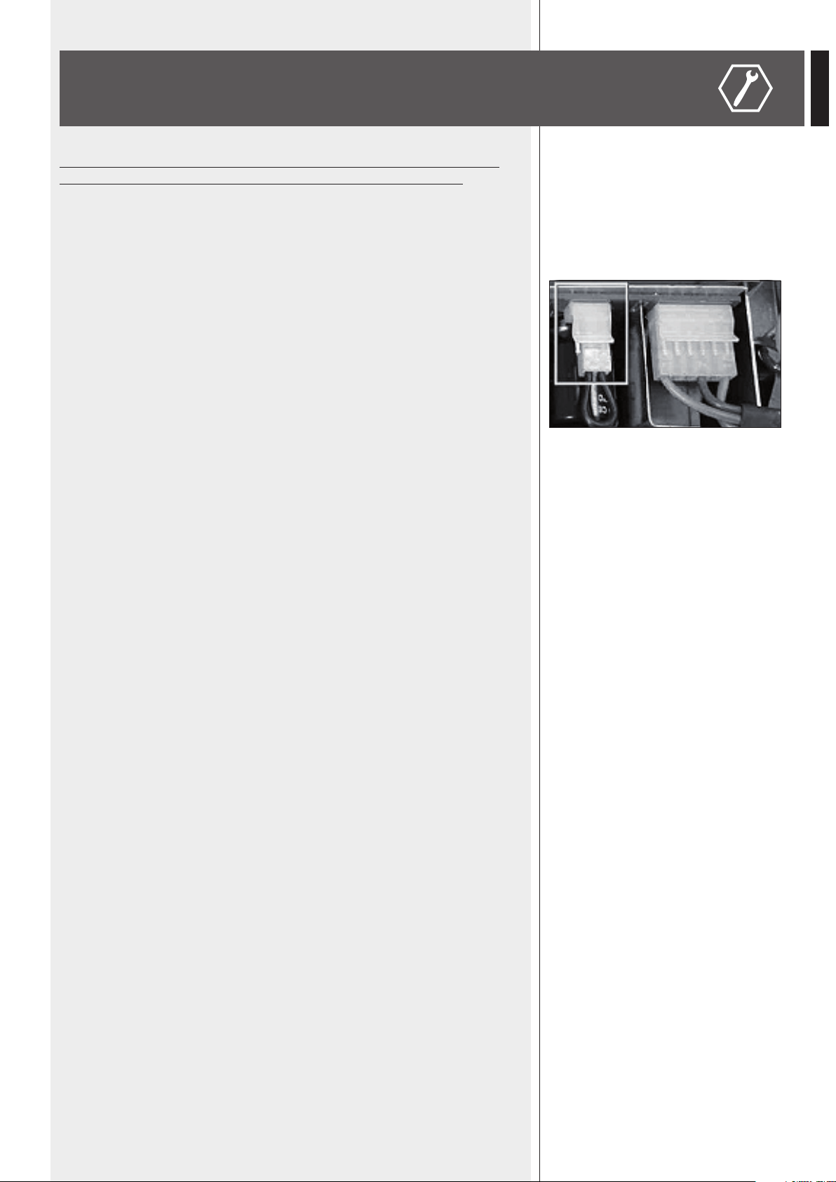
Individuare il connettore per il cambio di tensione 230 / 115 V dell'alimentatore (nella
foto è evidenziato con un quadrato):
In accordo con la serigraa del circuito, con tensione di rete 230 V porre (o lasciare)
il connettore nella posizione 230 V, con tensione di rete 115 V porre (o lasciare) il
connettore nella posizione 115 V.
Rimontare il coperchio superiore dell'apparecchio.
Prima di collegare l'apparecchio rete, assicurarsi che il fusibile inserito nel connettore per
l'alimentazione (posto sul pannello posteriore) sia quello corretto per la tensione in uso
(leggere le indicazioni poste sotto il connettore stesso).
30
ITALIANO
DATI TECNICI
AMPLIFICATORE
Potenza d’uscita (RMS) 80 W
Risposta in frequenza 50 Hz ÷ 16 kHz
Rapporto segnale / rumore
- Ingressi 1 e 2
- Ingresso AUX INPUT (sul retro)
60 dB
80 dB
Distorsione (a 1 kHz, potenza nom.) < 0,3 %
Controlli toni MP3 / AUX INPUT
- Bass (bassi)
- Treble (alti)
– 9 ÷ + 6 dB @ 100 Hz
– 14 ÷ + 8 dB @ 10 kHz
Filtro passa-alto (ingressi 1 e 2) 150 Hz
Sensibilità d’ingresso / impedenza
- Ingressi 1 e 2, livello microfonico
- Ingressi 1 e 2, livello linea
- Ingresso AUX INPUT (sul retro)
Bilanciato, – 62 dBu (max – 25 dBu ) / 10 kΩ
Bilanciato, – 29 dBu (max 0 dBu) / 10 kΩ
Regolabile – 18 ÷ + 20 dBu / 20 kΩ
Tensione / corrente “Phantom power” 30 V / 18 mA
Uscite diffusori
Bassa impedenza
Tensione costante
4 Ω
70 V (63 Ω) / 100 V (125 Ω)
PROTEZIONI
Amplicatore Sovraccarico, cortocircuito, termica
Alimentazione Fusibili di rete
GENERALE
Tensione di alimentazione 115-230V / 50-60 Hz
Potenza assorbita 160 W
Dimensioni (l, h, p) 442 mm, 88 mm, 230 mm (2 unità rack 19”)
Peso (Netto) 3,9 kg

31
ITALIANO
ESEMPIO COLLEGAMENTI
A
Canovi
Manini
PL010775
ES 3080
15/05/14
1:1
15/05/14
UNI EN 22768-1
EN 22768-1
Manini
Canovi
A
Serigraa Frame
Frame Silk-Screen
Emissione documento/Production release
1
1
A termine di legge ci riserviamo la proprieta' di questo disegno con divieto di riproduzione e renderlo noto a terzi senza nostra autorizzazione scritta
ELETTROACUSTICHE
INDUSTRIE
QUOTE SENZA INDICAZIONE DI TOLLERANZA.
DIMENSIONS WITHOUT TOLLERANCE INDICATIONS.
GRADO DI PRECISIONE/ACCURACY
CODICE/PART NUMBER
MATRICOLA
OGGETTO MODIFICA/MODIFY OBJECT
CONTR.
CHECK
DISEGN.
DRAWN
DATA
DATE
N.
DISEGN.
DRAWN
CONTR.
CHECKED
DATA/DATE
Descrizione
Description
Materiale
Material
Tratt. TERMICO
HEAT treatment
Tratt. SUPERFICIALE
SURFACE treat.
FOGLIO/SHEET FOGLI/SHEETS
SCALA/SCALE
Vedi Note
See Notes
Vedi Note / See Notes
Vedi Note / See Notes
NOTES:
NOTE:
- Serigrafare colore BIANCO.
- Silk-screen printing color WHITE.
- Dimensioni Pannello
- Panel Dimension
430
86
80W AUDIO SOURCE
& MIXER AMPLIFIER
RADIO/TUNER
BM 3001 MIC.

10307477 RevC
www.rcfaudio.com
HEADQUARTERS:
RCF S.p.A. Italy
tel. +39 0522 274 411
e-mail: info@rcf.it
RCF UK
tel. 0844 745 1234
Int. +44 870 626 3142
e-mail: info@rcfaudio.co.uk
RCF France
tel. +33 1 49 01 02 31
e-mail: france@rcf.it
RCF Germany
tel. +49 2203 925370
e-mail: germany@rcf.it
RCF Spain
tel. +34 91 817 42 66
e-mail: info@rcfaudio.es
RCF Belgium
tel. +32 (0) 3 - 3268104
e-mail: belgium@rcf.it
RCF USA Inc.
tel. +1 (603) 926-4604
e-mail: [email protected]
Except possible errors and omissions.
RCF S.p.A. reserves the right to make modications without prior notice.
Salvo eventuali errori ed omissioni.
RCF S.p.A. si riserva il diritto di apportare modiche senza preavviso.