
OWNER MANUAL
AM2160
AM2320
MIXER-AMPLIFIER

2
ENGLISH
ENGLISH
Safety precautions
Product information
Front panel
Rear panel
Operation
Loudspeaker connection
Power supply voltage change
Example of connection
Specifications
ITALIANO
Avvertenze per la sicurezza
Descrizione generale
Pannello frontale
Pannello posteriore
Funzionamento
Collegamento dei diffusori acustici
Cambio tensione di funzionamento dell’apparecchio
Esempio collegamenti
Dati tecnici
FRANCAIS
Consignes de sécurité
Description
Face avant
Panneau arrière
Fonctionnement
Connexion des enceintes
Modifier le voltage de l’alimentation
Exemple de connexion
Spécifications
DEUTSCH
Sicherheitsvorkehrungen
Gerätebeschreibung
Frontplatte
Rückseite
Bedienung
Lautsprecheranschlüsse
Netzspannungseinstellung
Anschlussbeispiele
Technische Daten
3
5
5
6
9
11
12
12
13
14
16
16
17
20
21
23
23
24
25
27
27
28
31
33
34
34
35
36
38
38
39
42
44
45
45
46
INDEX

3
ENGLISH
Before connecting and using this product, please read this instruction manual carefully and
keep it on hand for future reference. The manual is to be considered an integral part of
this product and must accompany it when it changes ownership as a reference for correct
installation and use as well as for the safety precautions.
RCF S.p.A. will not assume any responsibility for the incorrect installation and / or use of
this product.
WARNING: To prevent the risk of fire or electric shock, never expose this product to rain
or humidity.
SAFETY PRECAUTIONS
1. All the precautions, in particular the safety ones, must be read with special attention, as
they provide important information.
2. POWER SUPPLY FROM MAINS (direct connection)
a. The mains voltage is sufficiently high to involve a risk of electrocution; therefore, never
install or connect this product when its power cable is plugged in.
b. Before powering up, make sure that all the connections have been made correctly and
the voltage of your mains corresponds to the voltage shown on the rating plate on the
unit, if not, please contact your RCF dealer.
c. The metallic parts of the unit are earthed by means of the power cable.
d. Protect the power cable from damage.
e. To prevent the risk of electric shock, never open the product: there are no parts inside
that the user needs to access.
3. Make sure that no objects or liquids can get into this product, as this may cause a short
circuit. This apparatus shall not be exposed to dripping or splashing. No objects filled with
liquid, such as vases, shall be placed on this apparatus. No naked sources (such as lighted
candles) should be placed on this apparatus.
4. Never attempt to carry out any operations, modifications or repairs that are not expressly
described in this manual.
Contact your authorized service centre or qualified personnel should any of the following
occur:
- the product does not function (or functions in an anomalous way).
- The power supply cable has been damaged.
- Objects or liquids have got in the unit.
- The product has been subject to a heavy impact.
5. If this product is not used for a long period, disconnect the power cable.
6. If this product begins emitting any strange odours or smoke, switch it off immediately
and disconnect the power supply cable.
7. The terminals marked with the symbol
are HAZARDOUS LIVE and their connection
is to be made by an INSTRUCTED PERSON or the use of ready-made cables is required.
8. Do not connect this product to any equipment or accessories not foreseen.
For suspended installation, only use the dedicated anchoring points and do not try to hang
this product by using elements that are unsuitable or not specific for this purpose.
Also check the suitability of the support surface to which the product is anchored (wall,
ceiling, structure, etc.), and the components used for attachment (screw anchors, screws,
brackets not supplied by RCF etc.), which must guarantee the security of the system /
installation over time, also considering, for example, the mechanical vibrations normally
generated by transducers.
To prevent the risk of falling equipment, do not stack multiple units of this product unless
this possibility is specified in the user manual.
SAFETY
PRECAUTIONS
IMPORTANT NOTES
WARNING

4
ENGLISH
9. RCF S.p.A. strongly recommends this product is only installed by professional
qualified installers (or specialised firms) who can ensure correct installation
and certify it according to the regulations in force.
The entire audio system must comply with the current standards and regulations
regarding electrical systems.
10. Supports and trolleys
The equipment should be only used on trolleys or supports, where necessary, that are
recommended by the manufacturer. The equipment / support / trolley assembly must be
moved with extreme caution. Sudden stops, excessive pushing force and uneven floors may
cause the assembly to overturn.
11. There are numerous mechanical and electrical factors to be considered when installing
a professional audio system (in addition to those which are strictly acoustic, such as sound
pressure, angles of coverage, frequency response, etc.).
12. Hearing loss
Exposure to high sound levels can cause permanent hearing loss. The acoustic pressure
level that leads to hearing loss is different from person to person and depends on the
duration of exposure. To prevent potentially dangerous exposure to high levels of acoustic
pressure, anyone who is exposed to these levels should use adequate protection devices.
When a transducer capable of producing high sound levels is being used, it is therefore
necessary to wear ear plugs or protective earphones.
See the technical specifications in loudspeaker instruction manuals to know their maximum
sound pressure levels.
IMPORTANT NOTES
To prevent the occurrence of noise on microphone / line signal cables, use screened cables
only and avoid putting them close to:
- equipment that produces high-intensity electromagnetic fields (for example, high power
transformers).
- Mains cables.
- Loudspeaker lines.
OPERATING PRECAUTIONS
- Do not obstruct the ventilation grilles of the unit. Situate this product far from any heat
sources and always ensure adequate air circulation around the ventilation grilles.
- Do not overload this product for a long time.
- Never force the control elements (keys, knobs, etc. ).
- Do not use solvents, alcohol, benzene or other volatile substances for cleaning the
external parts of this product.
OPERATING PRECAUTIONS
IMPORTANT NOTES
5
ENGLISH
RCF S.p.A. would like to thank you for having purchased this product, which
has been designed to guarantee reliability and high performance.
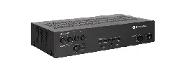
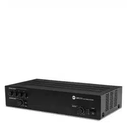
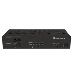
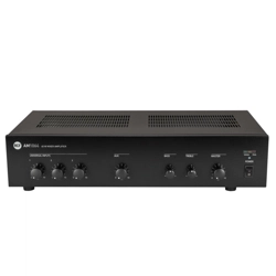
AM 2160 and AM 2320 are mixer-amplifiers with 4 mic-line audio inputs on removable
connectors (the first input also has an XLR socket) and 2 aux inputs for music sources (e.g.
CD players, tuners, etc.).
Both the models have identical features, but the nominal power: AM 2160 is a 160 W
amplifier; AM 2320 is a 320 W amplifier.
The amplifier output is available either for low impedance loudspeakers (min. 4 Ω) or 100
- 70 V constant voltage line (for loudspeakers having 100 - 70 V transformers).
Input 1 has a signal detection circuit (‘VOX’) providing automatic priority operation.
All inputs 1, 2, 3 and 4 can access the priority through an external command (connected to
the removable connector). Inputs 2 and 3 also have an RJ 45 socket for quick connection
of an RCF BM 3001 paging microphone (through CAT5 cable).
The MUSIC ON HOLD aux output allows to send the music (the output signal of the device
connected to the AUX INPUT A) to additional amplifiers, mixers, phone systems (‘music on
hold’ function), etc.
The 4 mic.-line inputs have a common ‘presence’ control and separate high-pass filters that
are useful for improving speech intelligibility.
The 2 aux inputs have independent tone controls (common for both aux inputs).
Front panel LED’s indicate the device state (ON, PROT), the priority activation (PRIOR) and
the signal level (SIG/PK).
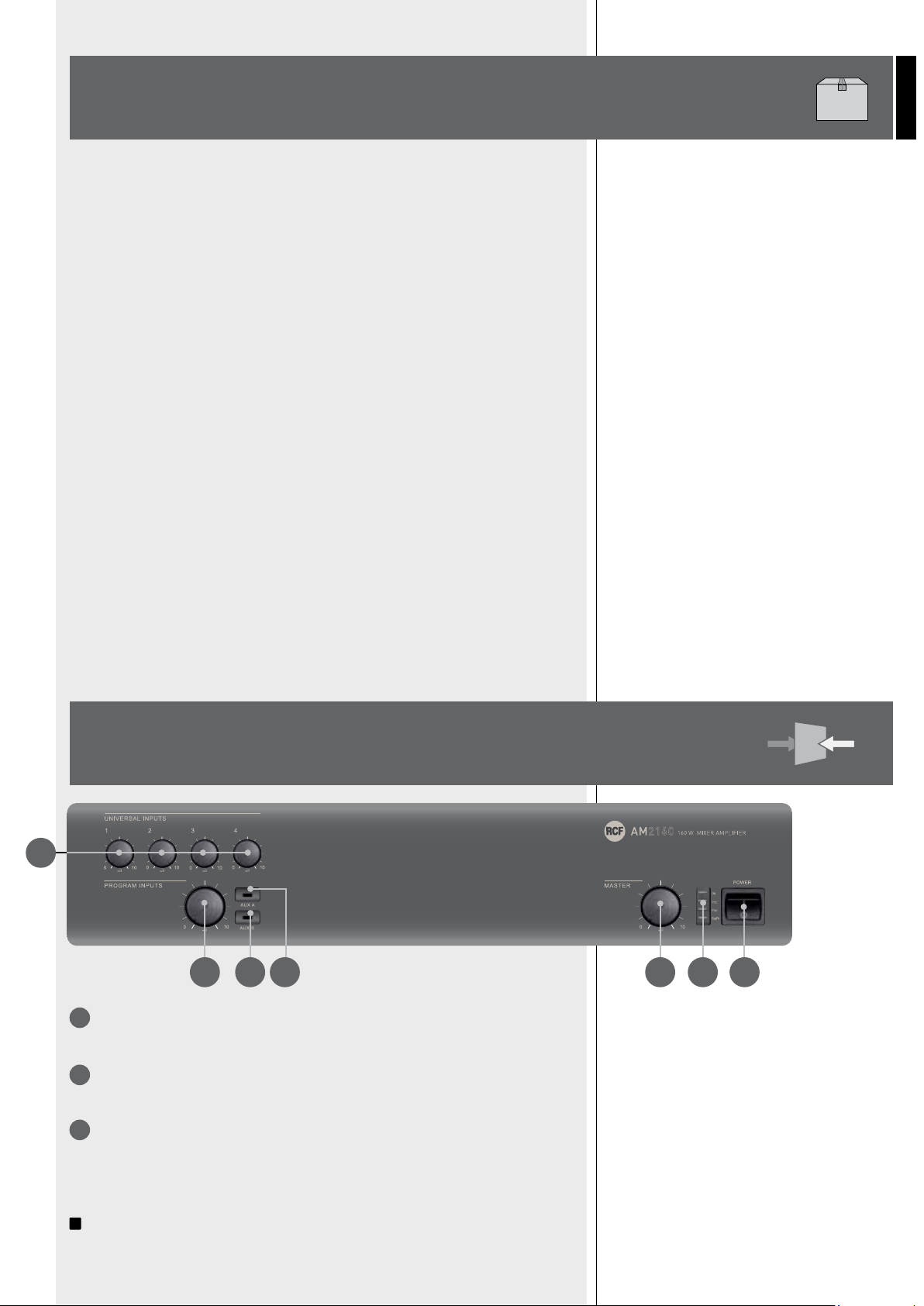
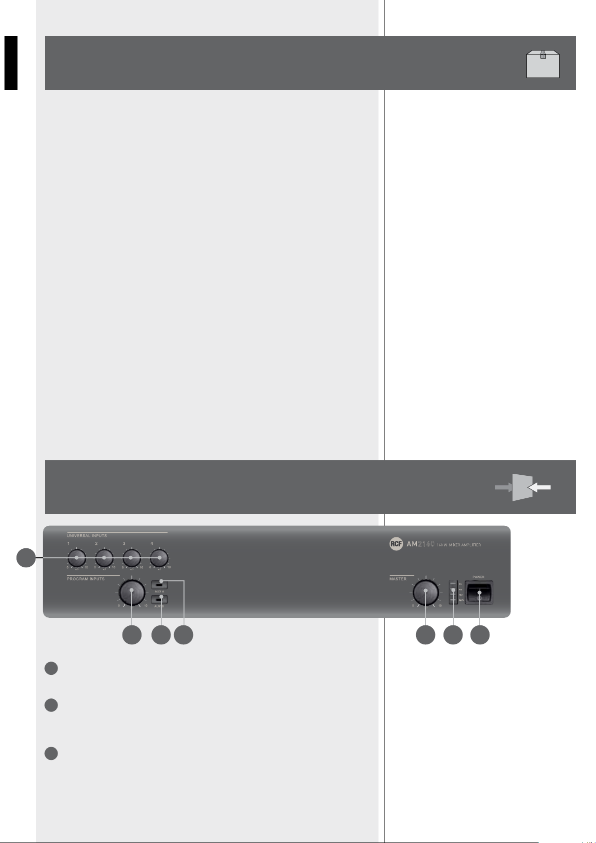
VOLUME CONTROLS FOR EACH UNIVERSAL INPUT (1, 2, 3, 4).
Note: unused channels should always be turned counterclockwise (to 0).
AUX INPUT VOLUME CONTROL.
Note: turn counterclockwise (to 0) if aux inputs are not used.
AUX A BUTTON (with LED).
It turns on (LED is lit) / off the AUX INPUT A to the internal amplifier (and PRE OUT).
If activated, the AUX INPUT B signal will not be sent to the internal amplifier (the AUX B
button LED will turn off).
i
The AUX INPUT A signal is always sent to the MUSIC ON HOLD output (that is not
affected by the AUX A and AUX B buttons).
PRODUCT
INFORMATIONS
FRONT PANEL
2
3
1
1
2 4 3 5 6 7
6
ENGLISH
AUX B BUTTON (WITH LED).
It turns on (LED is lit) / off the AUX INPUT B to the internal amplifier (and PRE OUT).
If activated, the AUX INPUT A signal will not be sent to the internal amplifier (the AUX A
button LED will turn off).
It takes 10 seconds (after pressing either the AUX A or the AUX B button) to store on its
memory the last selection.
INTERNAL AMPLIFIER MASTER VOLUME CONTROL.
Note: the audio outputs having RCA connectors (MUSIC ON HOLD and PRE OUT) are not
affected by the MASTER volume control.
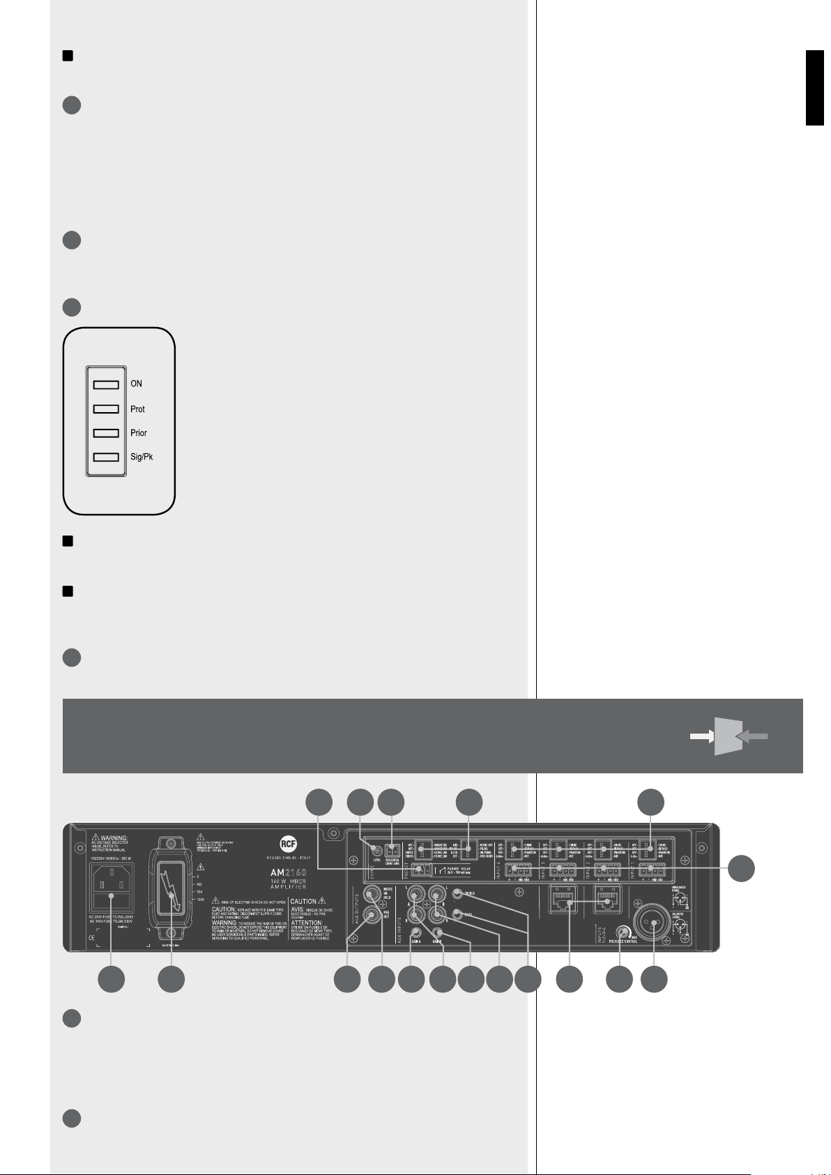
LEDs.
ON green: the device is switched on
PROT red: overload protection
orange: thermal protection
PRIOR yellow: priority by either the VOX function or an universal
input or the SEQ. COMMAND.
SIG/PK green: the signal level is higher than – 15 dB
green + red: the signal level is in the 0 ÷ +2 dB range
red: the signal level is equal or higher than +3 dB
i
0 dB = signal level that allows to get the amplifier maximum power.
i
The internal ‘limiter’ circuit helps to avoid the amplifier overloading, yet it is advisable to
reduce the MASTER volume (or a single channel volume where a too high signal is present)
when the SIG/PK LED is continuously indicating red.
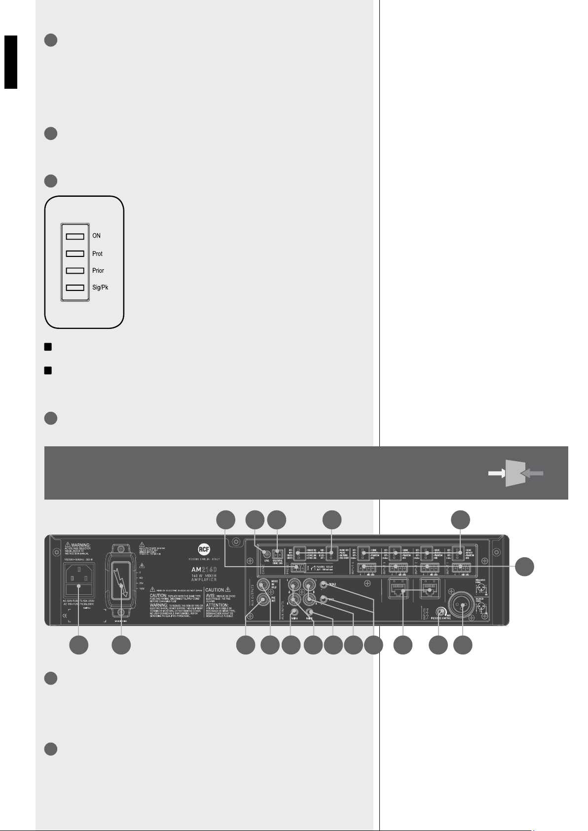
MAIN POWER SWITCH (0 = OFF; I = ON).
2 RJ 45 SOCKETS (CHANNELS 2 AND 3) TO CONNECT AN RCF BM 3001 PAGING
MICROPHONE PER SOCKET.
Note: when a BM 3001 paging microphone is connected, it is necessary to set the dip-
switches 3 and 4 of the relevant channel to the -20 dBu + PHANTOM mode (see 10
below).
4 BALANCED AUDIO INPUTS (CHANNELS 1, 2, 3, 4) WITH SOCKETS FOR REMOVABLE
CONNECTORS.
7
8
9
4
5
6
REAR
PANEL
9
1020222123
25 24 18 19 15 14 17 16 13 8 12 11
7
ENGLISH
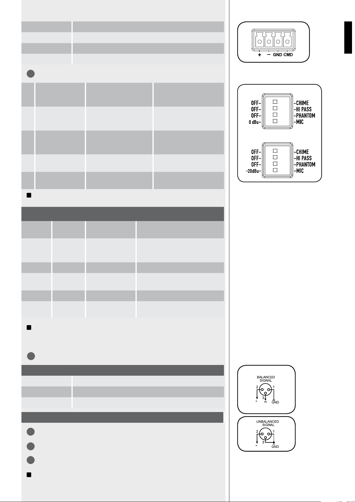
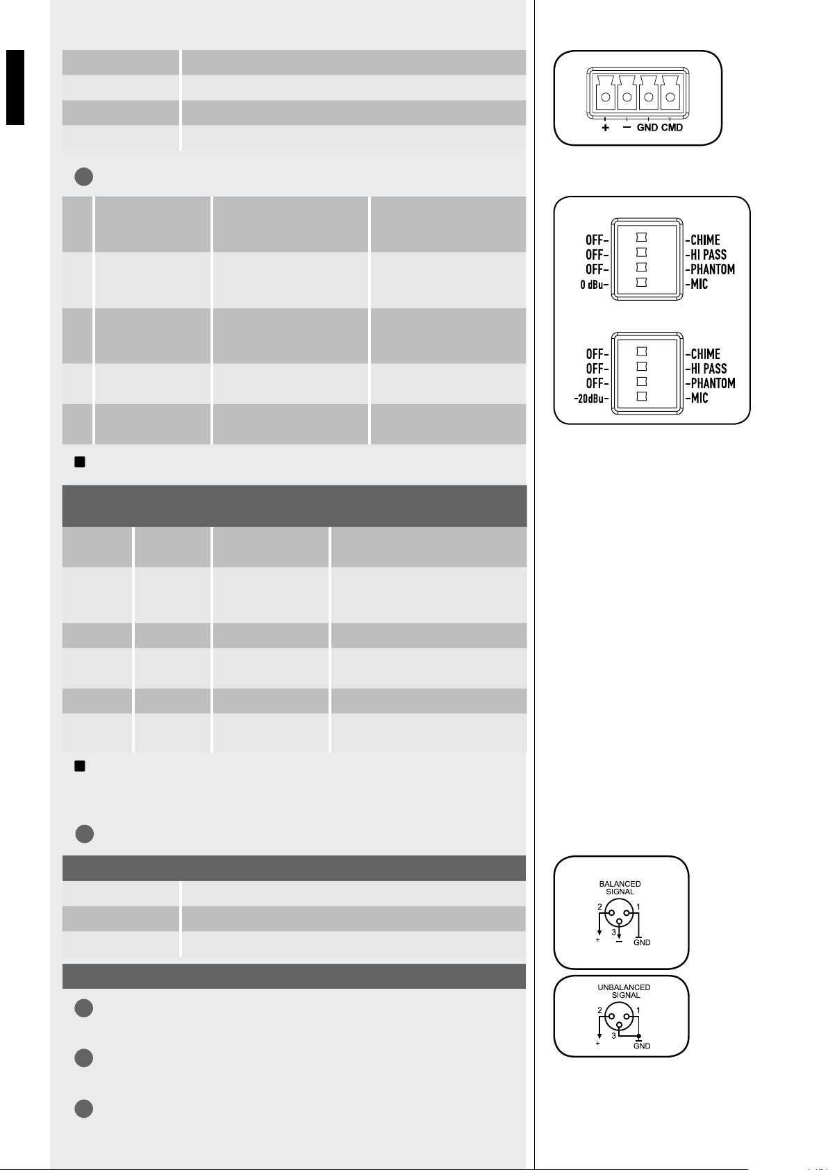
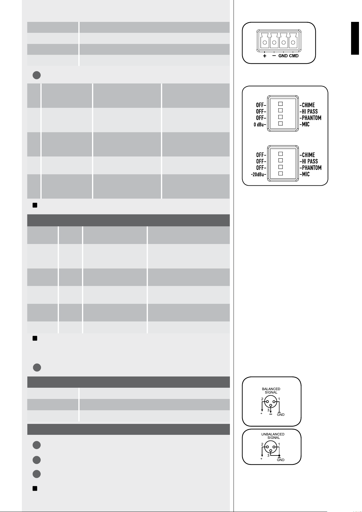
EACH CHANNEL HAS 4 DIP-SWITCHES:
i
Examples of dip-switches 3 and 4 settings:
i
When a BM 3001 paging microphone is used, it is necessary to choose the ‘-20 dBu +
PHANTOM’ mode in the relevant channel (dip-switch no.3 set to PHANTOM; dip-switch
no.4 set to -20 dBu).
CHANNEL NO.1 XLR INPUT.
PRESENCE CONTROL (F = 2.15 KHZ) COMMON FOR ALL THE CHANNELS 1, 2, 3, 4.
AUX INPUT (A & B) TREBLE AND BASS CONTROLS.
AUX INPUT A WITH DUAL RCA CONNECTOR.
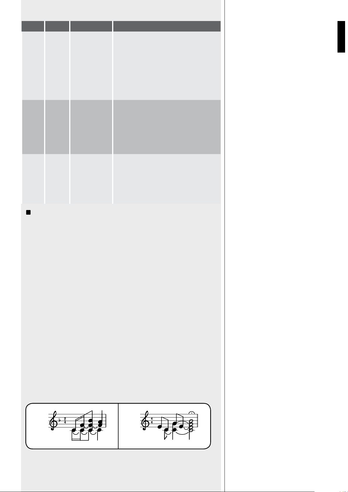
i
The two channels of the stereo source connected to the AUX INPUT A are summed
+ Hot audio input
– Cold audio input
GND Ground
CMD Command – priority access when connected to ground
BALANCED CONNECTION
+ Hot
- Cold
GND Ground
UNBALANCED CONNECTION
IN 1
IN 2-3-4
DIP 3 DIP 4 MODO USE (EXAMPLES)
OFF 0 dBu 0 dBu (CHANNEL 1). CD/MP3 players, tuners, message players,
phone systems.
PHANTOM 0 dBu 0 dBu + PHANTOM
(CHANNEL 1).
Pre-amplified (0 dBu output) paging
microphone that needs ‘phantom’ power
supply.
OFF -20 dBu -20 dBu (IN. 2, 3, 4). Audio source having a -20 dBu output.
PHANTOM -20 dBu -20 dBu + PHANTOM
(CHANNELS 2, 3, 4).
BM 3001 paging microphone.
OFF MIC MIC. Dynamic microphones.
PHANTOM MIC MIC + PHANTOM. Electret microphones.
1 OFF – CHIME OFF: the chime is disabled. CHIME: the chime will be played
as soon as a priority command is
activated.
2 OFF – HI PASS OFF: the audio hi-pass filter
is not inserted (flat frequency
response).
HI PASS: the audio hi-pass filter
is inserted.
3 OFF – PHANTOM OFF: the PHANTOM power
supply is not available on the
relevant audio input.
PHANTOM: the PHANTOM
power supply is available on the
relevant audio input.
4 CHANNEL 1
0 dBu – MIC
0 dBu: input level = 0 dBu
(775 mV).
MIC: microphone audio input.
5 CHANNELS 2, 3, 4
-20 dBu – MIC
-20 dBu: input level = -20 dBu
(78 mV).
MIC: microphone audio input.
10
11
12
13
14

8
ENGLISH
internally (to get a mono signal); the same for the stereo source connected to the AUX
INPUT B.
AUX INPUT A GAIN CONTROL.
AUX INPUT B WITH DUAL RCA CONNECTOR.
AUX INPUT B GAIN CONTROL.
PRE OUT audio output (with RCA connector) that sends the same signal routed to the
internal amplifier (signal that can be either a single source with priority or the mix of all the
channels 1, 2, 3, 4 and the selected AUX INPUT).
i
Use PRE OUT for connection of additional external amplifiers.
MUSIC ON HOLD AUDIO OUTPUT (with RCA connector) that sends a mono signal of
the source connected to the AUX INPUT A.
i
The MUSIC ON HOLD output (if an external music source has been connected to the
AUX INPUT A) can be used for the connection to a telephone system (in order to have the
‘music on hold’ function).
8 DIP-SWITCHES PRESET TO SET THE PRIORITY OPTIONS:
19
20
1.
MIX –
MUSIC OFF
MIX: the selected AUX INPUT is
always present in the (mixed)
signal sent to the amplifier, even
during a priority command.
MUSIC OFF: the selected AUX
INPUT is not sent to the amplifier
during a priority command.
2.
PRIO INPUT 1
PRIO INPUT 2
PR. IN1: the channel 1 has the
highest priority level with override
(but the CHIME SEQUENTIAL
COMMAND) through the relevant
command (or VOX), if the dip-
switch no.3 has been set to
‘graduated priority’.
PR. IN2: the channel 2 has the
highest priority level with override
(but the CHIME SEQUENTIAL
COMMAND) through the relevant
command, if the dip-switch
no.3 has been set to ‘graduated
priority’.
3.
I/LCK –
GR. PRIOR.
I/LCK: interlocked priority mode
(read the ‘Operation’ section).
GR. PRIOR.: graduated priority
mode (read the ‘Operation’
section).
4.
OFF –
VOX ON IN1
OFF: the channel 1 VOX function
is off.
VOX ON IN1: the channel 1 VOX
function is on (automatic priority
when a signal is detected on the
audio INPUT 1).
5.
OFF –
SMART IN2
OFF: the channel 2 priority is kept
only if the relevant command is
still present (‘push’ mode).
SMART IN2: the channel 2 priority
is switched on / off by every
impulse of the relevant command
(‘toggle’ mode).
6.
OFF –
SMART IN3
OFF: the channel 3 priority is kept
only if the relevant command is
still present (‘push’ mode).
SMART IN3: the channel 3 priority
is switched on / off by every
impulse of the relevant command
(‘toggle’ mode).
7.
SHORT –
CHIME LNG
SHORT: short chime
(before paging).
CHIME LONG: long chime
(before paging).
8.
SHORT –
CHIME LNG
SHORT: the short chime is
continuously played when the
‘CHIME SEQUENTIAL COMMAND’
is activated.
CHIME LONG: the long chime is
continuously played when the
‘CHIME SEQUENTIAL COMMAND’
is activated.
15
16
17
18

9
ENGLISH
1 2 3
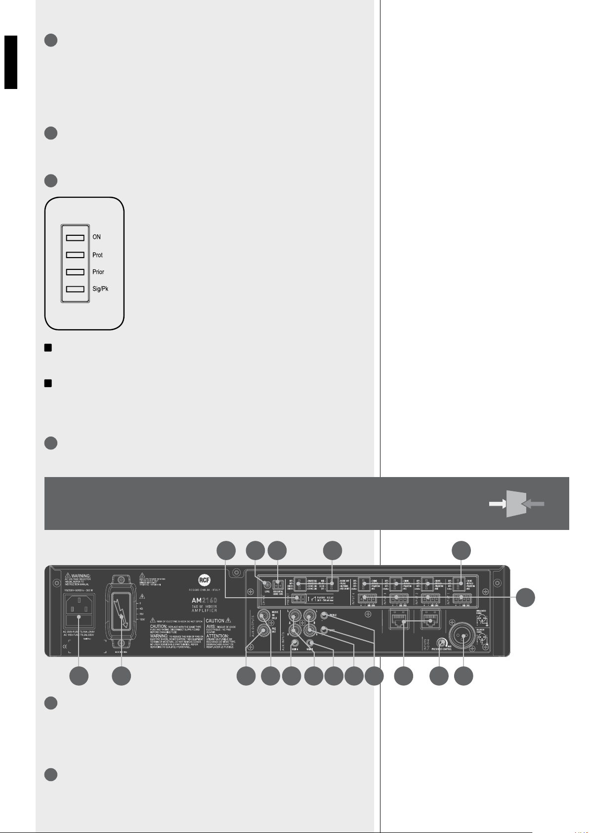
CHIME LEVEL (a trimmer adjustable by using a small screwdriver).
CHIME SEQUENTIAL COMMAND WITH REMOVABLE CONNECTOR (activated when
the 2 pins are short-circuited) to send the chime continuously (the chime type can be
selected by the dip-switch no.8, see 20-8).
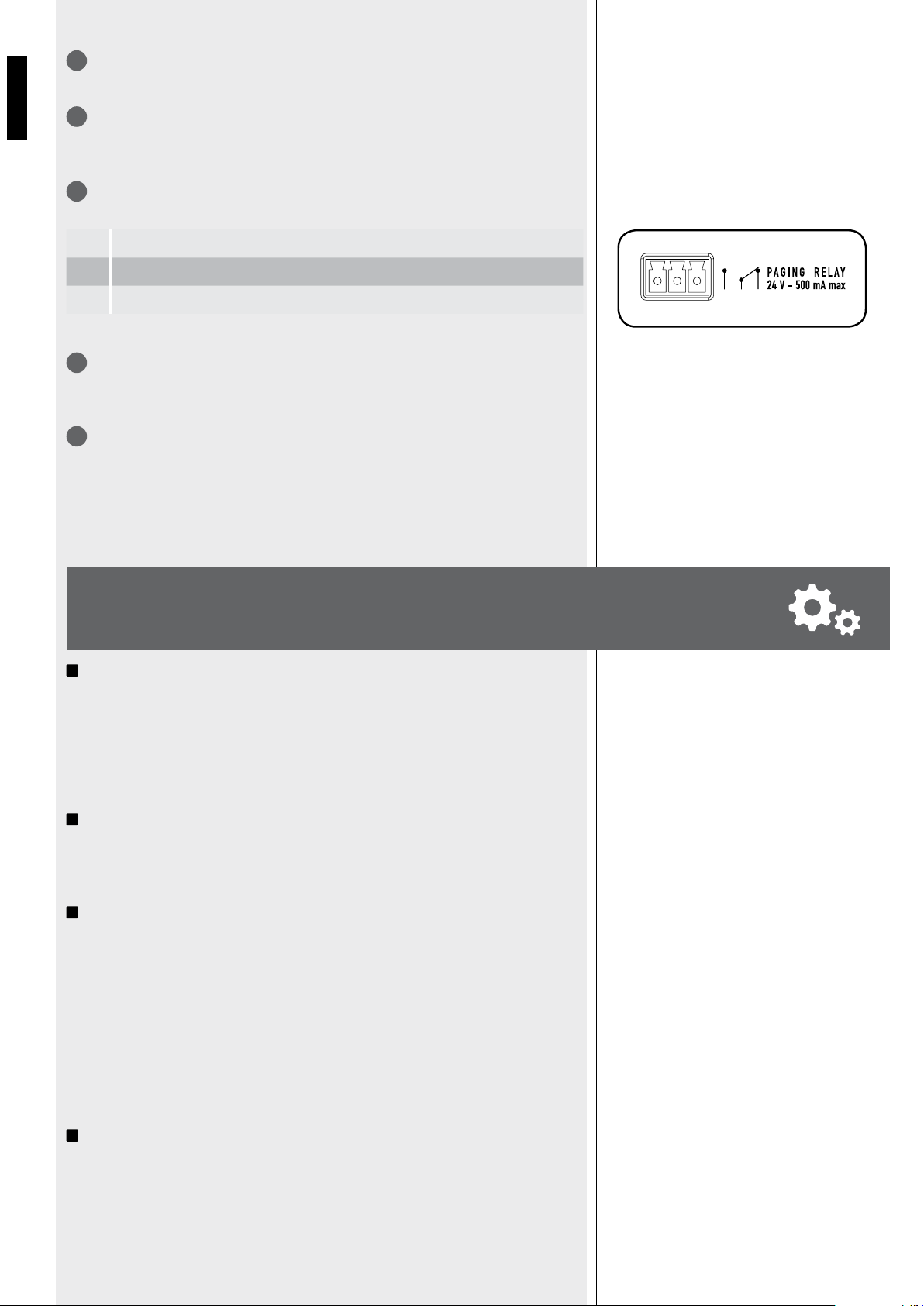
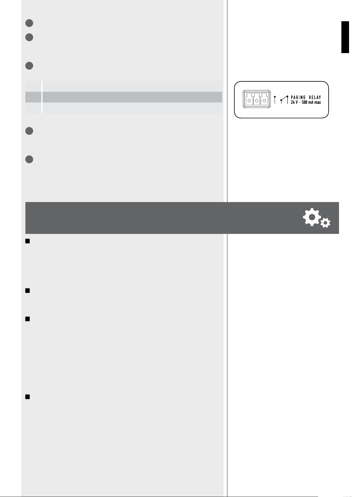
PAGING RELAY CONTACTS (3 PIN REMOVABLE CONNECTOR).
The internal relays switches when a priority command is present.
Max. voltage on contacts: 24 V; max. current: 0.5 A
AMPLIFIER OUTPUT (AM 2160: max. 160 W; AM 2320: max. 320 W) to loudspeakers
(100 / 70 V constant voltage line – 4 Ω impedance).
Use 1 output only (read the section ‘Loudspeaker connection’).
MAINS CONNECTOR WITH FUSE.
Before connecting the power supply cable, verify that the apparatus voltage (230 or 115 V
ac) corresponds to the available mains supply.
Note: the fuse type is marked on the rear panel (below the mains connector).
i
VOX’ is an internal circuit that automatically activates the channel 1 priority when a
signal is detected on the audio INPUT 1.
If no priority command is present (including VOX and CHIME SEQUENTIAL COMMAND), all
the channels 1, 2, 3, 4 and the selected AUX INPUT are mixed together.
i
The music volume (coming from a CD / MP3 player, a tuner, etc.) depends on the aux
input volume control on the front panel (see 2) and also the relevant GAIN control setting
(see 15 and 17) on the rear panel.
i
The aux inputs can be activated / muted through the front panel buttons (see 3 and 4).
PRIORITY
If a priority command is present (or VOX), the selected AUX INPUT can be either included
in the mixed signal sent to the amplifier or excluded, according to dip-switch no.1 setting
(see 20: the 8 dip-switch group).
During a priority command (‘PRIOR’ LED turns on), only the audio signal of the channel
with priority (and an AUX INPUT, if turned on) is sent to the amplifier (and the PRE OUT
output).
i
The selected aux input is always excluded from the signal sent to the amplifier when the
CHIME SEQUENTIAL COMMAND is activated.
The priority mode and the VOX function are set through the dip-switches no.2 and no.3 of
the 8 dip-switch group (see 20):
OPERATION
1 Normally open
2 Commonv
3 Normally closed
22
23
24
25
POWER ON (OR WHEN
A PRIORITY COMMAND ENDS)
21
10
ENGLISH
i
The dip-switch no.2 (8 dip-switch group) allows you to switch the priority level between
the channels 1 and 2. This setting does not work in the interlocked priority mode.
As soon as a priority event ends, the initial state will be restored (the channels 1, 2, 3, 4 and
the selected aux input will be mixed together, unless another priority event is in progress).
The chime sequential command makes the chime (short or long, depending on the dip-switch
no.8 setting, see 20) be continuously repeated. This command has the highest priority level
and always removes the selected aux input from the signal sent to the amplifier.
The dip-switches no.5 and no.6 (8 dip-switch group, see 20) allow choice of priority mode
for channels 2 and 3 between ‘push’ (the priority is kept only if the command is still present)
and ‘toggle’ (the priority is switched on / off by every impulse of the command).
Note: the chosen priority mode is applied to both BM 3001 paging microphones (if present)
and priority commands (of removable connectors).
Each input gain can be set to either MIC or -20 dBu (0 dBu for the channel 1). It is also
possible to turn the PHANTOM power supply on/off, to insert / remove the high-pass filter
and to enable / disable the chime, which is played on every priority event.
The chime is not played when using the channel 1 VOX function (a priority command is
needed to play the chime).
Its melody can be either short or long (dip-switch no.7 of the 8 dip-switch group, see 20).
When the chime is playing (a few seconds), the selected aux input is not sent to the
amplifier.
Channels 2 and 3 have an input with RJ 45 socket, to which a BM 3001 paging microphone
DIP 2 DIP 3 MODE
… I/LCK INTERLOCKED
Only the first priority command of channels
1÷4 (and also channel 1 VOX, if enabled
through the dip-switch no.4) is accepted.
Any other priority command will not be
accepted until the previous is removed.
Note: the only event that can always
be activated later (and can override a
previous priority) is the CHIME SEQUENTIAL
COMMAND.
PRIO
IN1
GR.
PRIOR.
GRADUATED
PRIORITY 1
A priority command having a higher level can
override the previous one.
The priority levels are:
1. (highest) CHIME SEQUENTIAL COMMAND
2. channel 1 (including VOX)
3. channel 2
4. channel 3
5. channel 4
PRIO
IN2
GR.
PRIOR.
GRADUATED
PRIORITY 2
A priority command having a higher level can
override the previous one.
The priority levels are:
1. (highest) CHIME SEQUENTIAL COMMAND
2. channel 2
3. channel 1 (including VOX)
4. channel 3
5. channel 4
CHIME SEQUENTIAL COMMAND
CHANNEL 2 - 3 ‘PUSH’ /
‘TOGGLE’ PRIORITY MODE
4 DIP-SWITCH GROUP
(PER EACH CHANNEL 1÷4)
INFORMATION
ABOUT THE CHIME
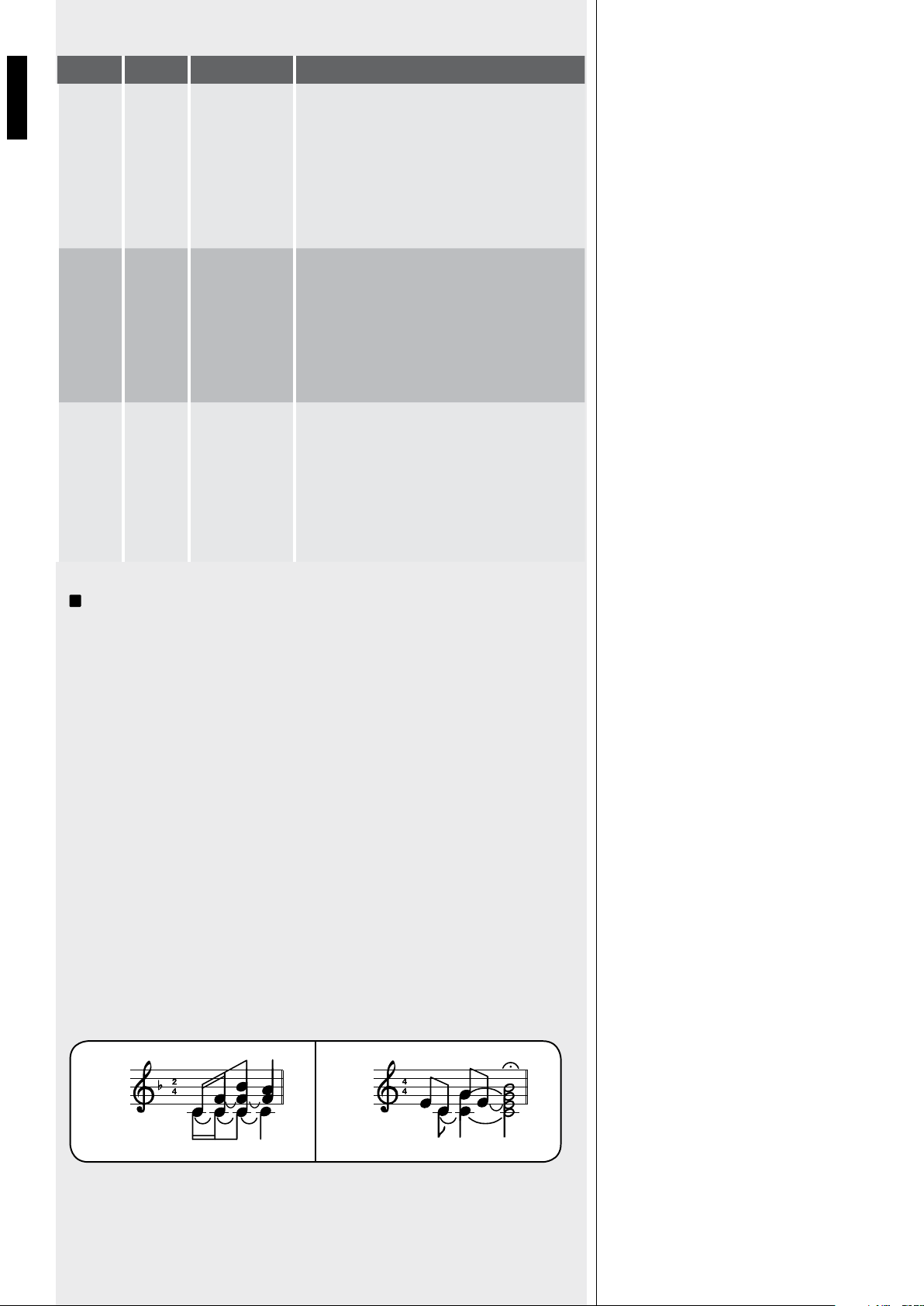
SHORT LONG
11
ENGLISH
can be connected (note: it is necessary to set the dip-switches no.3 and no.4 to the ‘-20
dBu + PHANTOM’ mode, see 10, second table).
i
When the BM 3001 paging microphone is on (ready to talk), its LED turns ON.
When the chime is playing (if chime is enabled), the BM 3001 microphone is momentarily
muted.
The paging microphone priority mode depends on the settings mentioned above.
The paging microphone is muted by events having a higher priority level (than the channel
2 or 3, to which the paging microphone is connected).
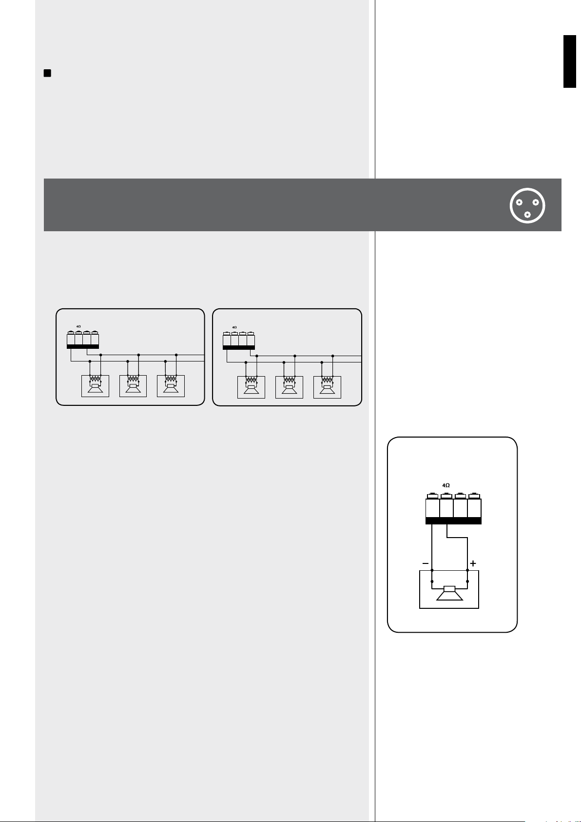
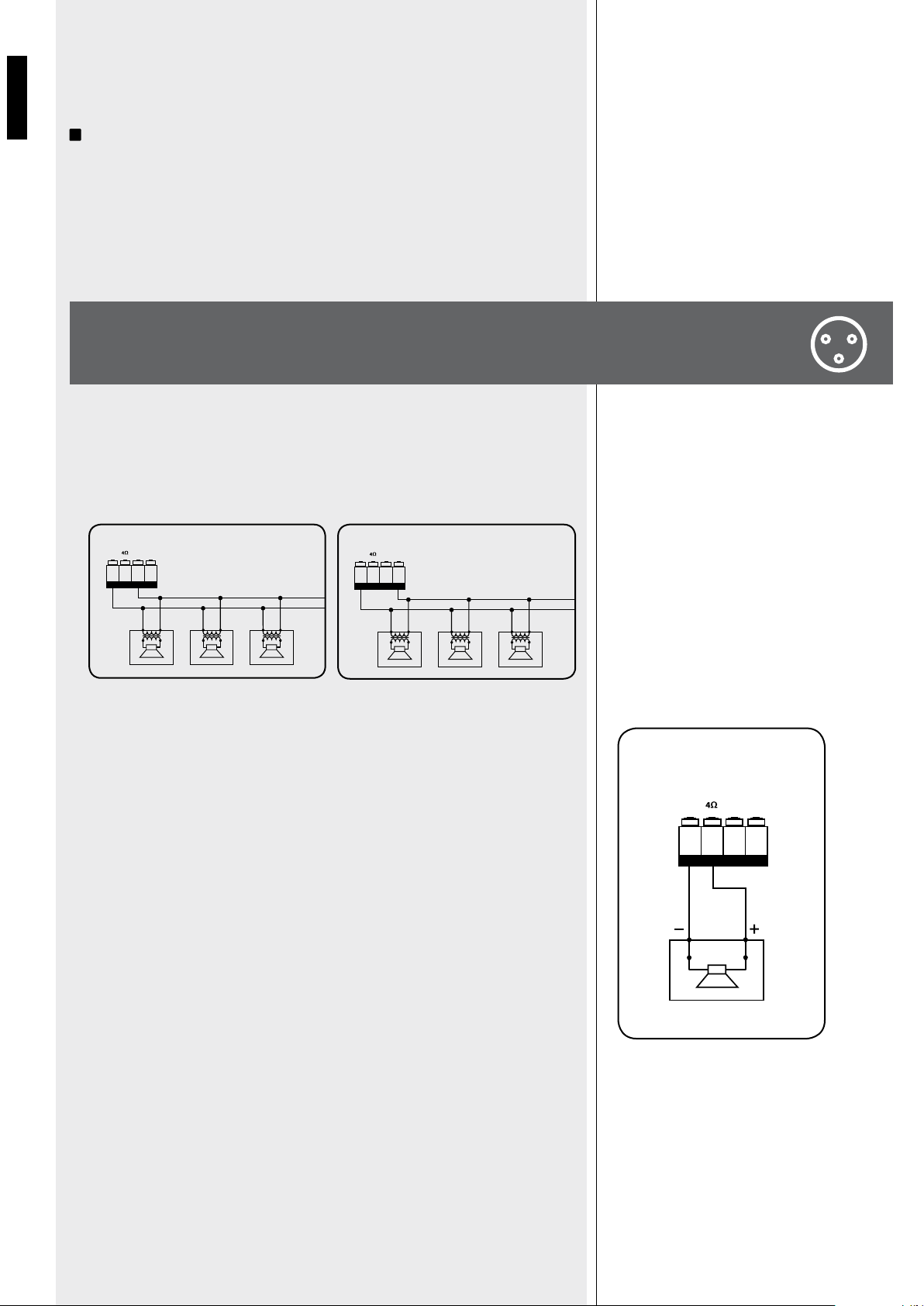
Use 1 output only, DO NOT MIX 100 / 70 V and 4 Ω CONNECTIONS!
- Each loudspeaker shall have a line transformer with the input voltage equal to the line
voltage (70 / 100 V).
- The loudspeaker total power shall not be higher than the amplifier maximum power.
- The loudspeaker total impedance shall not be lower than 4 Ω. Note: a total impedance
equal to 4 Ω allows the amplifier maximum power delivery. A higher impedance leads to a
reduction of the power delivered by the amplifier (e.g. 8 Ω: approx. ½ power, 16 Ω: approx.
¼ power). An impedance lower than 4 Ω overloads the amplifier.
- Loudspeaker models shall be chosen by considering the max. power (AM 2160: 160 W
on a 4 Ω load; AM 2320: 320 W on a 4 Ω load) that the amplifier can deliver.
- Loudspeaker line should be as short as possible; long cables may need large wire
cross-sections.
- Do not use, at the same time, both the low impedance output (4 Ω) and the constant
voltage output (70V or 100V), as this overloads the amplifier.
100V0
POWER OUTPUT
100V70VCOM
100V0 100V0
100 V
70V0
POWER OUTPUT
100V70VCO M
70V0 70V0
70 V
POWER OUTPUT
100V70VCOM
LOUDSPEAKER
CONNECTION
RCF BM 3001 PAGING
MICROPHONE (NOT INCLUDED)
70 / 100 V CONSTANT VOLTAGE
OUTPUTS
LOW IMPEDANCE OUTPUT (4 Ω)
12
ENGLISH
IMPORTANT: This manual section is for qualified personnel only.
The following instructions are to be ignored by the user.
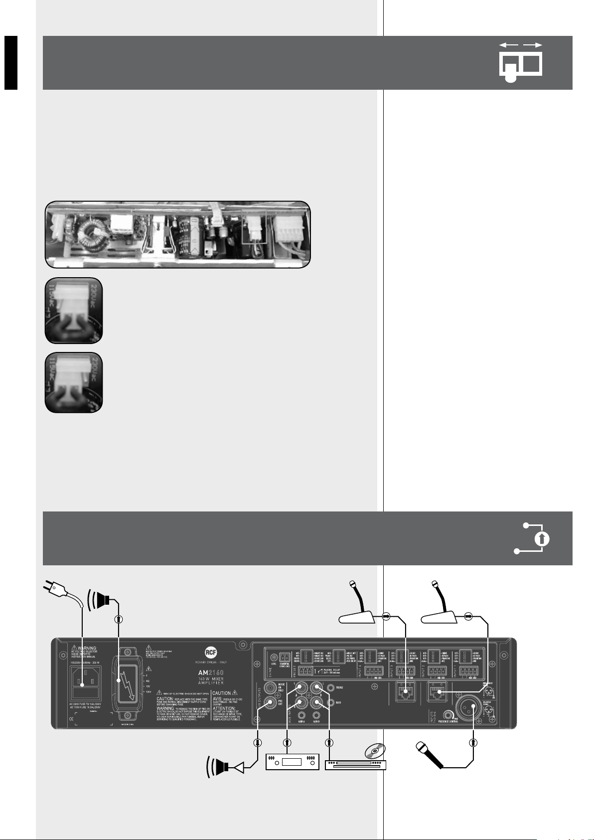
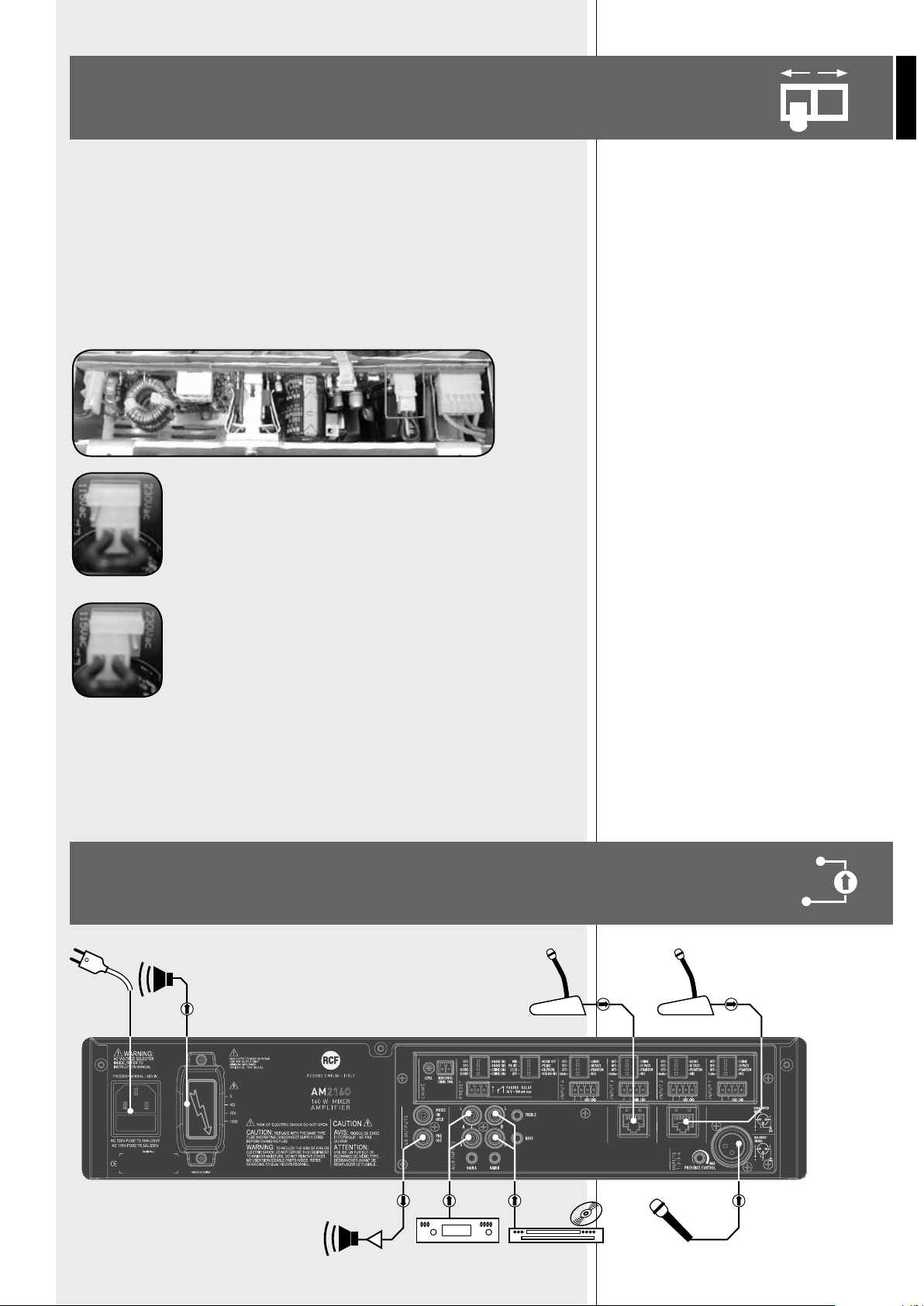
Make sure the device is not connected to the mains (unplug the power supply cable).
Remove the lid.
The voltage change connector is highlighted by a square.
If the mains voltage is 230 V, set the connector to the 230Vac
position (see the picture 2), according to the PCB indication (looking
at the connector front, the central pin is connected to the right one).
If the mains voltage is 115 V, set the connector to the 115 Vac
position (see the picture 3), according to the PCB indication (looking
at the connector front, the central pin is connected to the left one).
Refit the device lid.
Before connecting the device to the mains, make sure that the fuse (inside the IEC power
supply connector of the rear panel, see 25) is the correct current rating for the mains
voltages (read the fuse indication below the connector).
POWER SUPPLY
VOLTAGE CHANGE
EXAMPLE OF
CONNECTION
BM 3001 BM 3001
CD/DVDCD/DVD
230V
115V

13
ENGLISH
SPECIFICATIONS
µ
÷
±
AMPLIFIER
Output (RMS) power
Frequency response
SIGNAL / NOISE RATIO
Channels 1 ÷ 4
Aux
Distortion (at 1 kHz, nominal power)
AUX INPUT TONE CONTROLS
Bass
Treble
PRESENCE control (inputs 1 ÷ 4)
High-pass filter (inputs 1 ÷ 4)
INPUT SENSITIVITY / IMPEDANCE
MIC (channels 1 ÷ 4)
-20 dBu (channels 2 ÷ 4)
0 dBu (channel 1)
AUX INPUT (A, B)
AUX OUTPUT level / impedance
(pre / music on hold)
‘Phantom power’ voltage / current
LOUDSPEAKER OUTPUTS
Low impedance
Constant voltage (AM 2160)
Constant voltage (AM 2320)
PROTECTIONS
Amplifier
Power supply
GENERIC
Operating voltage
Power (consumption)
Dimensions (w, h, d)
Net weight
160 W (AM 2160), 320 W (AM 2320)
50 Hz ÷ 13.5 kHz
60 dB
80 dB
< 0.3 %
± 8 dB @ 80 Hz
± 8 dB @ 13 kHz
+ 10 dB @ 2.15 kHz
150 Hz
Balanced, – 56 dBu (max – 25 dBu ) / 10 kΩ
Balanced, – 28 dBu (max 0 dBu) / 5 kΩ
Balanced, – 7 dBu (max + 19 dBu) / 10 kΩ
Adjustable – 4 ÷ + 15 dBu (max +22 dBu) / 20 kΩ
– 1 dBu / 600 Ω
32 V / 18 mA
4 Ω
70 V (31 Ω) / 100 V (62 Ω)
70V (16 Ω) / 100 V (31 Ω)
Overload, short circuit, thermal
fuses
115-230V / 50-60 Hz
350 W (AM 2160), 600 W (AM 2320)
442 mm, 88 mm, 230 mm (2U 19” rack)
4.8 kg (AM 2160), 6.2 kg (AM 2320)

14
ITALIANO
Prima di collegare ed utilizzare questo prodotto, leggere attentamente le istruzioni
contenute in questo manuale, il quale è da conservare per riferimenti futuri. Il presente
manuale costituisce parte integrante del prodotto e deve accompagnare quest’ultimo anche
nei passaggi di proprietà, per permettere al nuovo proprietario di conoscere le modalità
d’installazione e d’utilizzo e le avvertenze per la sicurezza.
L’installazione e l’utilizzo errati del prodotto esimono la RCF S.p.A. da ogni responsabilità.
ATTENZIONE: Per prevenire i rischi di fiamme o scosse elettriche, non esporre mai questo
prodotto alla pioggia o all’umidità.
AVVERTENZE PER LA SICUREZZA
1. Tutte le avvertenze, in particolare quelle relative alla sicurezza, devono essere lette con
particolare attenzione, in quanto contengono importanti informazioni.
2. ALIMENTAZIONE DIRETTA DA RETE
a. La tensione di alimentazione dell’apparecchio ha un valore sufficientemente alto da
costituire un rischio di folgorazione per le persone: non procedere mai all’installazione
o connessione dell’apparecchio con il cavo d’alimentazione collegato alla rete.
b. Prima di alimentare questo prodotto, assicurarsi che tutte le connessioni siano corrette
e che la tensione della vostra rete di alimentazione corrisponda quella di targa
dell’apparecchio, in caso contrario rivolgetevi ad un rivenditore RCF.
c. Le parti metalliche dell’apparecchio sono collegate a terra tramite il cavo di
alimentazione. Un apparecchio avente costruzione di CLASSE I deve essere connesso
alla presa di rete con un collegamento alla terra di protezione.
d. Accertarsi che il cavo di alimentazione dell’apparecchio non possa essere calpestato o
schiacciato da oggetti, al fine di salvaguardarne la perfetta integrità.
e. Per evitare il rischio di shock elettrici, non aprire mai l’apparecchio: all’interno non vi
sono parti che possono essere utilizzate dall’utente.
3. Impedire che oggetti o liquidi entrino all’interno del prodotto, perché potrebbero causare
un corto circuito. L’apparecchio non deve essere esposto a stillicidio o a spruzzi d’acqua;
nessun oggetto pieno di liquido, quali vasi, deve essere posto sull’apparecchio.
Nessuna sorgente di fiamma nuda (es. candele accese) deve essere posta sull’apparecchio.
4. Non eseguire sul prodotto interventi / modifiche / riparazioni se non quelle espressamente
descritte sul manuale istruzioni.
Contattare centri di assistenza autorizzati o personale altamente qualificato quando:
l’apparecchio non funziona (o funziona in modo anomalo);
- il cavo di alimentazione ha subito gravi danni;
- oggetti o liquidi sono entrati nell’apparecchio;
- l’apparecchio ha subito forti urti.
5. Qualora questo prodotto non sia utilizzato per lunghi periodi, scollegare il cavo
d’alimentazione.
6. Nel caso che dal prodotto provengano odori anomali o fumo, spegnerlo immediatamente
e scollegare il cavo d’alimentazione.
7. I terminali marcati con il simbolo
sono da ritenersi ATTIVI e PERICOLOSI ed il loro
collegamento deve essere effettuato da PERSONE ADDESTRATE oppure si devono utilizzare
cavi già pronti.
8. Non collegare a questo prodotto altri apparecchi e accessori non previsti.
Quando è prevista l’installazione sospesa, utilizzare solamente gli appositi punti di ancoraggio
e non cercare di appendere questo prodotto tramite elementi non idonei o previsti allo scopo.
Verificare inoltre l’idoneità del supporto (parete, soffitto, struttura ecc., al quale è ancorato
il prodotto) e dei componenti utilizzati per il fissaggio (tasselli, viti, staffe non fornite da
RCF ecc.) che devono garantire la sicurezza dell’impianto / installazione nel tempo, anche
considerando, ad esempio, vibrazioni meccaniche normalmente generate da un trasduttore.
AVVERTENZE PER
LA SICUREZZA
IMPORTANTE
ATTENZIONE

15
ITALIANO
Per evitare il pericolo di cadute, non sovrapporre fra loro più unità di questo prodotto, quando
questa possibilità non è espressamente contemplata dal manuale istruzioni.
9. La RCF S.p.A. raccomanda vivamente che l’installazione di questo prodotto
sia eseguita solamente da installatori professionali qualificati (oppure da ditte
specializzate) in grado di farla correttamente e certificarla in accordo con le
normative vigenti. Tutto il sistema audio dovrà essere in conformità con le
norme e le leggi vigenti in materia di impianti elettrici.
10. Sostegni e Carrelli
Se previsto, il prodotto va utilizzato solo su carrelli o sostegni consigliati dal produttore.
L’insieme apparecchio-sostegno / carrello va mosso con estrema cura. Arresti improvvisi, spinte
eccessive e superfici irregolari o inclinate possono provocare il ribaltamento dell’assieme.
11. Vi sono numerosi fattori meccanici ed elettrici da considerare quando si installa un
sistema audio professionale (oltre a quelli prettamente acustici, come la pressione sonora,
gli angoli di copertura, la risposta in frequenza, ecc.).
12. Perdita dell’udito
L’esposizione ad elevati livelli sonori può provocare la perdita permanente dell’udito. Il livello di
pressione acustica pericolosa per l’udito varia sensibilmente da persona a persona e dipende
dalla durata dell’esposizione. Per evitare un’esposizione potenzialmente pericolosa ad elevati
livelli di pressione acustica, è necessario che chiunque sia sottoposto a tali livelli utilizzi delle
adeguate protezioni; quando si fa funzionare un trasduttore in grado di produrre elevati livelli
sonori è necessario indossare dei tappi per orecchie o delle cuffie protettive.
Consultare i dati tecnici contenuti nei manuali istruzioni per conoscere le massime pressioni
sonore che i diffusori acustici sono in grado di produrre.
NOTE IMPORTANTI
Per evitare fenomeni di rumorosità indotta sui cavi che trasportano segnali dai microfoni o di
linea (per esempio 0dB), usare solo cavi schermati ed evitare di posarli nelle vicinanze di:
- apparecchiature che producono campi elettromagnetici di forte intensità (per esempio
trasformatori di grande di potenza);
- cavi di rete;
- linee che alimentano altoparlanti.
PRECAUZIONI D’USO
- Non ostruire le griglie di ventilazione dell’unità. Collocare il prodotto lontano da fonti
di calore e garantire la circolazione dell’aria in corrispondenza delle griglie di aerazione.
- Non sovraccaricare questo prodotto per lunghi periodi.
- Non forzare mai gli organi di comando (tasti, manopole ecc.).
- Non usare solventi, alcool, benzina o altre sostanze volatili per la pulitura delle parti
esterne dell’unità.
IMPORTANTE
PRECAUZIONI D’USO
16
ITALIANO
RCF S.p.A. Vi ringrazia per l’acquisto di questo prodotto, realizzato in modo da
garantirne l’affidabilità e prestazioni elevate.
AM 2160 e AM 2320 sono mixer-amplificatori aventi 4 ingressi audio mic.-linea su
connettori rimovibili (l’ingresso 1 dispone inoltre di connettore XLR) e 2 ingressi ausiliari
per eventuali sorgenti sonore esterne (es. lettori CD, sintonizzatori radio, ecc.).
Gli amplificatori AM 2160 e AM 2320 hanno caratteristiche identiche, tranne la loro
potenza nominale: quella del modello AM 2160 è 160 W, mentre quella del modello AM
2320 è 320 W. L’uscita per diffusori acustici è disponibile sia a bassa impedenza (min. 4 Ω)
oppure a tensione costante 100 – 70 V (per diffusori con trasformatore).
Un circuito di rilevazione del segnale (“VOX”) con funzione di attivazione della priorità
è presente sull’ingresso 1. Tutti gli ingressi 1, 2, 3 e 4 possono ottenere la priorità tramite
un comando esterno (collegato al connettore rimovibile); gli ingressi 2 e 3 hanno inoltre
un connettore RJ 45 per la rapida connessione di una base microfonica dedicata BM 3001
(utilizzando cavo CAT5).
È presente un’uscita MUSIC ON HOLD per inviare il segnale della sorgente musicale
collegata all’ingresso AUX INPUT A ad amplificatori addizionali oppure ad una centrale
telefonica (come musica d’attesa).
I 4 ingressi universali hanno un controllo comune di “presenza” e filtri passa-alto (inseribili
separatamente) utili per migliorare l’intelligibilità della voce; gli ingressi ausiliari AUX INPUT
A e B hanno controlli di tono separati (comuni per entrambi gli ingressi).
Sono presenti indicatori luminosi relativi allo stato dell’apparecchio (ON, PROT), all’attività
del circuito di priorità (PRIOR) ed al livello del segnale audio (SIG/PK).
CONTROLLI DEL VOLUME DI CIASCUN INGRESSO UNIVERSALE 1, 2, 3, 4.
Nota: nel caso uno o più ingressi non siano utilizzati, lasciare i relativi controlli a 0.
CONTROLLO DI VOLUME DELL’INGRESSO AUSILIARIO AUX INPUT SELEZIONATO
(A oppure B).
Nota: lasciare il controllo a 0 nel caso che gli ingressi ausiliari non siano utilizzati.
PULSANTE AUX A CON INDICATORE LUMINOSO.
Attiva (LED acceso) / disattiva l’ingresso ausiliario AUX INPUT A verso l’amplificatore
interno (ed anche l’uscita PRE OUT).
La sua attivazione esclude automaticamente (se attivato) l’ingresso ausiliario AUX INPUT B
(l’indicatore luminoso del pulsante AUX B si spegne).
DESCRIZIONE
GENERALE
2
3
1
PANNELLO
FRONTALE
1
2 4 3 5 6 7
17
ITALIANO
i
Il segnale presente all’ingresso AUX INPUT A è sempre riportato sull’uscita MUSIC ON
HOLD (non soggetta al controllo dei pulsanti AUX A e AUX B).
PULSANTE AUX B CON INDICATORE LUMINOSO.
Attiva (LED acceso) / disattiva l’ingresso ausiliario AUX INPUT B verso l’amplificatore interno
(ed anche l’uscita PRE OUT). La sua attivazione esclude automaticamente (se attivato)
l’ingresso ausiliario AUX INPUT A (l’indicatore luminoso del pulsante AUX A si spegne).
Trascorsi 10 secondi dopo aver premuto uno dei 2 pulsanti (AUX A oppure AUX B), l’ultima
selezione è automaticamente memorizzata.
CONTROLLO DI VOLUME PRINCIPALE (MASTER) DELL’AMPLIFICATORE INTERNO.
Nota: le uscite su connettori RCA (MUSIC ON HOLD e PRE OUT) non sono soggette a
questo controllo.
INDICATORI LUMINOSI (LED).
ON verde: l’apparecchio è acceso
PROT rosso: l’apparecchio è in protezione per sovraccarico
arancio: l’apparecchio è in protezione per riscaldamento eccessivo
PRIOR giallo: indica l’inserimento di qualsiasi priorità (VOX,
ingressi univ., SEQ. CMD.).
SIG/PK verde: il livello del segnale audio è superiore ad almeno -15 dB
verde + rosso: il livello del segnale audio è compreso tra 0 e +2 dB
rosso: il livello del segnale audio è uguale o superiore a +3 dB
i
0 dB = livello del segnale che permette di ottenere la massima potenza erogata
dall’amplificatore.
i
Il circuito “limiter” interno evita il superamento della potenza massima dell’amplificatore,
tuttavia è consigliabile abbassare il volume MASTER (oppure il singolo volume di un segnale
eccessivo) quando il LED SIG/PK è costantemente rosso.
INTERRUTTORE PRINCIPALE DELL’APPARECCHIO POWER (0 = SPENTO; I = ACCESO).
2 INGRESSI RELATIVI AI CANALI 2 E 3 CON PRESE RJ 45, per il collegamento di 2 basi
microfoniche RCF BM 3001 (una per ciascun ingresso).
Nota: nel caso sia utilizzata una base microfonica BM 3001, è necessario attivare la
modalità “-20 dBu + PHANTOM” tramite i microinterruttori / “dip-switch” 3 e 4 (vedere il
punto 10) del relativo canale.
4 INGRESSI AUDIO BILANCIATI con prese per connettori rimovibili relativi ai canali 1, 2, 3, 4.
7
8
9
4
5
6
PANNELLO
POSTERIORE
9
1020222123
25 24 18 19 15 14 17 16 13 8 12 11
18
ITALIANO
CIASCUN CANALE DISPONE DI 4 MICROINTERRUTTORI “DIP-SWITCH”:
i
Esempi di utilizzo dei microinterruttori 3 e 4:
i
Quando si utilizza una base microfonica BM 3001, è necessario impostare il modo “-20
dBu + PHANTOM” (dip-switch nr.3 su PHANTOM; dip-switch nr.4 su -20 dBu) nel rispettivo
canale.
INGRESSO AUDIO CANALE 1 CON CONNETTORE XLR.
CONTROLLO DI “PRESENZA” (TONI MEDI, F = 2,15 KHZ) PRESENCE CONTROL
COMUNE PER I CANALI 1, 2, 3, 4.
CONTROLLI DI TONO TREBLE (ALTI) E BASS (BASSI) COMUNI AGLI INGRESSI AUX
INPUT A E B.
INGRESSO AUDIO AUSILIARIO AUX INPUT A CON DOPPIO CONNETTORE RCA.
+ Hot audio input
– Cold audio input
GND Ground
CMD Command – priority access when connected to ground
COLLEGAMENTO BILANCIATO
+ Polo positivo
- Polo negativo
GND Massa
COLLEGAMENTO SBILANCIATO
IN 1
IN 2-3-4
DIP 3 DIP 4 MODO
ESEMPI DI POSSIBILI
COLLEGAMENTI
OFF 0 dBu 0 dBu (CHANNEL 1). CD/MP3 players, tuners, message
players, phone systems.
PHANTOM 0 dBu 0 dBu + PHANTOM
(CHANNEL 1).
Pre-amplified (0 dBu output) paging
microphone that needs ‘phantom’
power supply.
OFF -20 dBu -20 dBu (IN. 2, 3, 4). Audio source having a -20 dBu output.
PHANTOM -20 dBu -20 dBu + PHANTOM
(CHANNELS 2, 3, 4).
BM 3001 paging microphone.
OFF MIC MIC. Dynamic microphones.
PHANTOM MIC MIC + PHANTOM. Electret microphones.
1 OFF – CHIME OFF: the chime is disabled. CHIME: the chime will be
played as soon as a priority
command is activated.
2 OFF – HI PASS OFF: the audio hi-pass filter
is not inserted (flat frequency
response).
HI PASS: the audio hi-pass
filter is inserted.
3 OFF – PHANTOM OFF: the PHANTOM power
supply is not available on the
relevant audio input.
PHANTOM: the PHANTOM
power supply is available on
the relevant audio input.
4 CHANNEL 1
0 dBu – MIC
0 dBu: input level = 0 dBu
(775 mV).
MIC: microphone audio input.
5 CHANNELS 2, 3, 4
-20 dBu – MIC
-20 dBu: input level = -20 dBu
(78 mV).
MIC: microphone audio input.
10
11
12
13
14

19
ITALIANO
i
I due canali del segnale stereo presente all’ingresso AUX INPUT A sono sommati in mono
all’interno dell’apparecchio; lo stesso per il segnale stereo presente all’ingresso AUX INPUT B.
CONTROLLO DI GUADAGNO GAIN A DELL’INGRESSO AUSILIARIO AUX INPUT A.
INGRESSO AUDIO AUSILIARIO AUX INPUT B CON DOPPIO CONNETTORE RCA.
CONTROLLO DI GUADAGNO GAIN B DELL’INGRESSO AUSILIARIO AUX INPUT B.
USCITA AUDIO (CON CONNETTORE RCA) PRE OUT, riportante lo stesso segnale inviato
all’amplificatore di potenza interno (segnale che può essere un evento prioritario oppure la
miscelazione dei canali 1, 2, 3, 4 e dell’ingresso audio ausiliare AUX INPUT selezionato).
i
L’uscita PRE OUT è utile al fine di collegare una o più unità di potenza esterne addizionali.
USCITA AUDIO (CON CONNETTORE RCA) MUSIC ON HOLD, riportante lo stesso
segnale (ma in mono) presente all’ingresso ausiliario AUX INPUT A.
i
L’uscita MUSIC ON HOLD (se è presente una sorgente musicale esterna all’ingresso AUX
INPUT A) può essere collegata ad una centrale telefonica in modo da ottenere la “musica
d’attesa”.
8 MICROINTERRUTTORI “DIP-SWITCH” PRESET PER LE IMPOSTAZIONI DI PRIORITÀ:
19
20
1.
MIX –
MUSIC OFF
MIX: l’ingresso AUX INPUT selezionato
rimane presente (in miscelazione) nel
segnale inviato all’amplificatore durante
l’attivazione di un comando di priorità.
MUSIC OFF: l’ingresso AUX INPUT
selezionato è tolto dal segnale
inviato all’amplificatore durante
l’attivazione di un comando di
priorità.
2.
PRIO INPUT 1
PRIO INPUT 2
PR. IN1: il canale 1 ha il livello più alto
di priorità con precedenza (eccetto il
comando “CHIME SEQ. COMMAND”),
tramite il relativo comando (o la
funzione “VOX”), se è impostata la
priorità scalare (“graduated priority”)
con il dip-switch nr.3.
PR. IN2: il canale 2 ha il livello più
alto di priorità con precedenza
(eccetto il comando “CHIME
SEQ. COMMAND”), tramite il
relativo comando, se è impostata
la priorità scalare (“graduated
priority”) con il dip-switch nr.3.
3.
I/LCK –
GR. PRIOR.
I/LCK (INTERLOCKED):
impostazione del modo di priorità
interbloccata (vedere la sezione
“funzionamento”).
GRADUATED PRIORITY:
impostazione del modo
di priorità scalare (vedere la
sezione “funzionamento”).
4.
OFF –
VOX ON IN1
OFF: disattivazione della funzione
“VOX”del canale 1.
VOX ON IN1: attivazione della
funzione “VOX” del canale 1
(attivazione automatica della
priorità quando è rilevato un
segnale all’ingresso audio INPUT 1).
5.
OFF –
SMART IN2
OFF: la priorità del canale 2 rimane
attiva solo quando il relativo
comando è presente.
SMART IN2: la priorità del canale
2 è controllata da un interruttore
elettronico interno bi-stabile
(on / off) che commuta ad ogni
comando ad impulso.
6.
OFF –
SMART IN3
OFF: La priorità del canale 3 rimane
attiva solo quando il relativo
comando è presente.
SMART IN3: la priorità del canale
3 è controllata da un interruttore
elettronico interno bi-stabile
(on / off) che commuta ad ogni
comando ad impulso.
7.
SHORT –
CHIME LNG
SHORT: selezione del primo tipo
(corto) della melodia di preavviso
(“chime”) da inviare prima di un
annuncio.
CHIME LONG: selezione del
secondo tipo (lungo) della
melodia di preavviso (“chime”)
da inviare prima di un annuncio.
8.
SHORT –
CHIME LNG
SHORT: selezione del primo tipo (corto)
della melodia di preavviso (“chime”)
da inviare quando si attiva il comando
“CHIME SEQUENTIALCOMMAND”.
CHIME LONG: selezione del
secondo tipo (lungo) della melodia
di preavviso (“chime”) da inviare
quando si attiva il comando “CHIME
SEQUENTIAL COMMAND”.
15
16
17
18
20
ITALIANO
1 2 3
CONTROLLO (TRIMMER REGOLABILE TRAMITE UN PICCOLO CACCIAVITE) CHIME
LEVEL DEL VOLUME DELLA MELODIA DI PREAVVISO “CHIME”.
COMANDO CHIME SEQUENTIAL COMMAND CON CONNETTORE RIMOVIBILE (attivo
quando i due contatti sono cortocircuitati) per l’invio continuo della melodia di preavviso
“chime” selezionabile tramite il dip-switch nr.8 (vedere la tabella al punto 20).
PAGING RELAY (connettore rimovibile a 3 poli): contatti di un relè interno per la
segnalazione della funzione di priorità attiva.
Max. tensione applicabile ai contatti: 24 V; portata: 0,5 A.
USCITE DI POTENZA (max. 160 W per il modello AM 2160, max. 320 W per AM 2320)
per i diffusori (a tensione costante 100 / 70 V; a bassa impedenza 4 Ω).
Utilizzare una sola uscita e vedere la sezione “Collegamento dei diffusori acustici”.
CONNETTORE CON FUSIBILE PER L’ALIMENTAZIONE PRINCIPALE DA RETE.
Prima di effettuare il collegamento, verificare che la tensione di rete corrisponda a quella
impostata (230 o 115 V) nell’apparecchio.
Nota: il tipo di fusibile da utilizzarsi è specificato sul pannello posteriore (sotto il
connettore).
i
Con il termine “VOX”, qui si intende un circuito interno all’apparecchio che attiva
automaticamente la priorità del canale 1 quando è rilevato un segnale all’ingresso audio
INPUT 1.
In assenza di qualsiasi comando di priorità attivo (oppure del VOX o del comando CHIME
SEQUENTIAL COMMAND), si ha la normale miscelazione dei canali 1, 2, 3, 4, insieme
all’eventuale ingresso ausiliario AUX INPUT selezionato.
i
Il volume della sorgente musicale (es. lettore CD, radio, ecc., collegata ad un ingresso
AUX INPUT) dipende dal controllo di volume degli ingressi ausiliari posto sul pannello
frontale dell’apparecchio (vedere punto 2) ed anche dall’impostazione del relativo controllo
di guadagno GAIN (vedere punti 15 e 17) posto sul pannello posteriore.
i
Gli ingressi ausiliari AUX INPUT possono essere attivati/disattivati tramite i pulsanti
(vedere punti 3 e 4) posti sul pannello frontale.
PRIORITY
In presenza di qualsiasi comando di priorità attivo (oppure del VOX), l’ingresso ausiliario
selezionato può comunque essere inviato (in miscelazione) all’amplificatore (oppure
escluso), in base all’impostazione del dip-switch nr.1 relativo al gruppo di 8 microinterruttori
(vedere punto 20).
Quando avviene un comando di priorità (LED “PRIOR” acceso), il segnale audio inviato
all’amplificatore (ed all’uscita PRE OUT) sarà solo quello del canale prioritario attivo (oltre
all’eventuale ingresso ausiliario, se abilitato).
i
L’ingresso ausiliario selezionato è sempre e comunque escluso dal segnale inviato
all’amplificatore quando è attivato il comando CHIME SEQUENTIAL COMMAND.
La modalità di attuazione della priorità (inclusa la funzione “VOX”) è impostata tramite i
dip-switch nr.2 e nr.3 del gruppo di 8 microinterruttori (vedere punto 20):
FUNZIONAMENTO
1 Contatto normalmente aperto
2 Contatto comune
3 Contatto normalmente chiuso
21
22
23
24
25
FUNZIONAMENTO
ALL’ACCENSIONE (OPPURE
AL TERMINE DI UNA PRIORITÀ)
21
ITALIANO
i
Il dip-switch nr.2 (gruppo di 8 microinterruttori) permette di scambiare il livello di
precedenza tra i canali 1 e 2; questa impostazione non ha effetto nel modo interbloccato.
Al termine di un evento di priorità, il sistema ripristinerà le condizioni iniziali (la miscelazione
dei canali 1, 2, 3, 4, più l’eventuale ingresso ausiliario selezionato, a meno che non sia stata
attivata nel frattempo una nuova priorità).
Il comando CHIME SEQUENTIAL COMMAND attiva la ripetizione continua della melodia di
preavviso “chime” (corta o lunga, a seconda dell’impostazione del dip-switch nr.8, vedere il
punto 20), ha la massima priorità e comporta sempre e comunque l’esclusione dell’ingresso
ausiliario selezionato dal segnale inviato all’amplificatore.
Mediante i dip-switch nr.5 e nr.6 (del gruppo di 8 microinterruttori; vedere il punto 20)
è possibile attivare le priorità relative ai canali 2 e 3 in modalità temporanea, ovvero la
priorità è mantenuta solo fino a quando il relativo comando è attivo, oppure in modo bi-
stabile (on / off) che commuta il suo stato ad ogni comando ad impulso.
Nota: la modalità prescelta si applica sia alla base microfonica BM 3001 (se presente), sia
quando si utilizza il comando di priorità (disponibile nel connettore rimovibile).
In ciascun canale è possibile impostare la sensibilità d’ingresso tra MIC e -20 dBu (0 dBu
per il canale 1), attivare l’alimentazione PHANTOM, inserire un filtro passa-alto ed abilitare
la melodia di preavviso “chime”, la quale è riprodotta ogni qualvolta si attiva la priorità.
La melodia di preavviso “chime” non è riprodotta quando si utilizza la funzione VOX del
canale 1, ma solo quando si attiva un comando di priorità.
La scelta della melodia (corta o lunga) si effettua tramite il dip-switch nr.7 (del gruppo di 8
microinterruttori, vedere il punto 20).
Durante il tempo di riproduzione della melodia di preavviso (pochi secondi), il
segnale dell’ingresso ausiliario selezionato (AUX INPUT A oppure B) non è diffuso
dall’amplificatore.
DIP 2 DIP 3 MODO
… I/LCK INTERBLOCCATO
È accettato solo il comando di priorità attivato per
primo in uno dei 4 canali (eventualmente anche la
funzione VOX, se abilitata mediante il dip-switch
nr.4). Nessun altro comando di priorità sarà
accettato fino a quando non sarà rimosso quello
precedente.
Nota: l’unico evento che può sempre inserirsi
successivamente (ed annullare una priorità
precedente) è il comando CHIME SEQUENTIAL
COMMAND.
PRIO
IN1
GR.
PRIOR.
PRIORITÀ
SCALARE 1
Un evento con priorità più alta ha la precedenza
(anche se attivato in successione). L’ordine di priorità è:
1. (più alta) comando CHIME SEQUENTIAL CMD
2. canale 1 (inclusa la funzione VOX)
3. canale 2
4. canale 3
5. canale 4
PRIO
IN2
GR.
PRIOR.
PRIORITÀ
SCALARE 2
Un evento con priorità più alta ha la precedenza (anche
se attivato in successione). L’ordine di priorità è:
1. (più alta) comando CHIME SEQUENTIAL CMD
2. canale 2
3. canale 1 (inclusa la funzione VOX)
4. canale 3
5. canale 4
SHORT LONG
“CHIME SEQUENTIAL
COMMAND”
MODALITÀ TEMPORANEA
O BI-STABILE DELLA PRIORITÀ
DEI CANALI 2 E 3
GRUPPO DI 4 MICROINTERRUTTORI
/ DIP-SWITCH PER CIASCUN
CANALE (DA 1 A 4)
INFORMAZIONI SULLA MELODIA
DI PREAVVISO “CHIME”
22
ITALIANO
I canali 2 e 3 hanno ciascuno un ingresso con connettore RJ 45, al quale è possibile
collegare una sola base microfonica RCF BM 3001 (nota: in tal caso è necessario attivare il
modo “-20 dBu + PHANTOM” tramite i “dip-switch” nr.3 e 4; vedere il punto 10).
i
Quando il microfono della base BM 3001 è attivo, si accende il suo LED.
Durante la melodia di preavviso “chime” (se abilitata), il microfono è momentaneamente
inabilitato.
La priorità e la modalità di funzionamento del tasto della base microfonica dipende dalle
varie impostazioni già descritte. La base microfonica è disattivata da eventi con livello di
priorità superiore rispetto al canale (2 o 3) a cui è collegata.
Utilizzare una sola uscita tra le 3 disponibili: 100 V, 70 V, 4 Ω.
- Ogni diffusore deve avere un trasformatore di linea con tensione d’ingresso uguale a
quella della linea (70 / 100 V).
- La somma delle potenze di tutti i diffusori collegati non deve essere superiore a quella
massima erogabile dall’amplificatore.
- L’impedenza totale dei diffusori non deve essere inferiore a 4 Ω. Nota: un’impedenza
complessiva uguale a 4 Ω permette la massima erogazione di potenza dell’amplificatore;
un’impedenza superiore comporta una riduzione della potenza erogata (es. 8 Ω:
circa ½ potenza; 16 Ω: circa ¼ potenza); un’impedenza inferiore a 4 Ω sovraccarica
l’amplificatore.
- La somma delle potenze dei diffusori deve essere adeguata alla potenza massima
erogabile dall’amplificatore (AM 2160: 160 W su 4 Ω; AM 2320: 320 W su 4 Ω).
- La lunghezza delle linee diffusori deve essere ridotta al minimo (una lunga distanza può
richiedere l’uso di cavi con sezioni elevate).
- Non utilizzare contemporaneamente il collegamento a bassa impedenza (4 Ω) e quello
ad alta impedenza (70V o 100V); fare ciò sovraccarica l’amplificatore.
100V0
POWER OUTPUT
100V70VCOM
100V0 100V0
100 V
70V0
POWER OUTPUT
100V70VCO M
70V0 70V0
70 V
POWER OUTPUT
100V70VCOM
COLLEGAMENTO DEI
DIFFUSORI ACUSTICI
BASE MICROFONICA RCF BM
3001 (NON INCLUSA)
USCITE A TENSIONE COSTANTE
70 / 100 V
USCITA BASSA IMPEDENZA (4 Ω)
23
ITALIANO
IMPORTANTE: La presente sezione del manuale riguarda il solo personale
qualificato. Le seguenti operazioni NON devono essere effettuate direttamente
dall’utente.
Togliere la tensione dall’apparecchio (staccando il cavo d’alimentazione dalla presa di rete).
Rimuovere il coperchio superiore dell’apparecchio.
Individuare il connettore per il cambio di tensione 230 / 115 V dell’alimentatore
(nella foto 1 è evidenziato con un quadrato).
Con tensione di rete 230 V, porre (o lasciare) il connettore nella
posizione 230Vac (vedere la foto 2) in accordo con la serigrafia del
circuito stampato (in modo che il polo centrale sia collegato a quello
destro, guardando il connettore frontalmente).
Con tensione di rete 115 V, porre (o lasciare) il connettore nella
posizione 115Vac (vedere la foto 3) in accordo con la serigrafia del
circuito stampato (in modo che il polo centrale sia collegato a quello
sinistro, guardando il connettore frontalmente).
Rimontare il coperchio superiore dell’apparecchio.
Prima di collegare l’apparecchio rete, assicurarsi che il fusibile inserito nel connettore per
l’alimentazione (posto sul pannello posteriore) sia quello corretto per la tensione in uso
(leggere le indicazioni poste sotto il connettore stesso).
CAMBIO
TENSIONE
ESEMPIO
COLLEGAMENTI
BM 3001 BM 3001
CD/DVDCD/DVD
230V
115V

24
ITALIANO
SPECIFICHE
µ
÷
±
AMPLIFICATORE
Potenza d’uscita (RMS)
Risposta in frequenza
RAPPORTO SEGNALE/RUMORE
Canali 1 ÷ 4
Aux
Distorsione (a 1 kHz, potenza nom.)
CONTROLLI TONI AUX INPUT
Bass
Treble
Controllo PRESENCE (ingressi 1 ÷ 4)
Filtro passa-alto (ingressi 1 ÷ 4)
SENSIBILITÀ D’INGRESSO / IMPEDENZA
MIC (canali 1 ÷ 4)
- 20 dBu (canali 2 ÷ 4)
0 dBu (canale 1)
AUX INPUT (A, B)
Livello d’uscita / impedenza
AUX OUTPUT (pre / music on hold)
Tensione / corrente “Phantom power”
USCITE DIFFUSORI
Bassa impedenza
Tensione costante (AM 2160)
Tensione costante (AM 2320)
PROTEZIONI
Amplificatore
Alimentazione
GENERALE
Tensione di alimentazione
Potenza assorbita
Dimensioni (l, h, p)
Peso (Netto)
160 W (AM 2160); 320 W (AM 2320)
50 Hz ÷ 13,5 kHz
60 dB
80 dB
< 0,3 %
± 8 dB @ 80 Hz
± 8 dB @ 13 kHz
+ 10 dB @ 2,15 kHz
150 Hz
Bilanciato, – 56 dBu (max – 25 dBu ) / 10 kΩ
Bilanciato, – 28 dBu (max 0 dBu) / 5 kΩ
Bilanciato, – 7 dBu (max + 19 dBu) / 10 kΩ
Regolabile – 4 ÷ + 15 dBu (max +22 dBu) / 20 kΩ
– 1 dBu / 600 Ω
32 V / 18 mA
4 Ω
70 V (31 Ω) / 100 V (62 Ω)
70 V (16 Ω) / 100 V (31 Ω)
Sovraccarico, corto circuito, termica
Fusibili di rete
115-230V / 50-60 Hz
350 W (AM 2160), 600 W (AM 2320)
442 mm, 88 mm, 230 mm (2 unità rack 19”)
4,8 kg (AM 2160); 6,2 kg (AM 2320)

25
FRANÇAIS
Avant de connecter et d’utiliser ce produit, veuillez lire ce manuel avec attention et le
conserver à portée de main pour pouvoir le consulter ultérieurement.
Le manuel doit être considéré comme faisant partie intégrante de ce produit et doit être
transmis lors de tout changement de propriétaire car il décrit l’installation et l’utilisation
correctes du produit ainsi que les précautions d’emploi à respecter.
RCF S.p.A. décline toute responsabilité concernant l’installation et/ou l’utilisation
incorrecte(s) de ce produit.
AVERTISSEMENT: Pour prévenir tout risque d’incendie et de choc électrique, n’exposez
jamais ce produit à la pluie ou à l’humidité.
CONSIGNES DE SÉCURITÉ
1. All the precautions, in particular the safety ones, must be read with special attention, as
they provide important information.
2. ALIMENTATION SECTEUR
a. La tension secteur est suffisamment élevée pour engendrer un risque d’électrocution ;
par conséquent, n’installez ou ne branchez jamais ce produit alors qu’il est allumé.
b. Avant d’allumer le produit, assurez-vous que toutes les connexions ont été réalisées
correctement et que la tension secteur correspond bien au voltage indiqué sur la
plaque d’identification du produit ; dans le cas contraire, veuillez contacter votre
revendeur RCF.
c. Les parties métalliques du produit sont reliées à la terre par l’intermédiaire du cordon
secteur. Tout produit de CLASSE I doit être branché à une prise terre.
d. Protégez le cordon secteur contre tout dommage ; assurez-vous qu’il est placé de
sorte qu’il ne soit ni piétiné, ni écrasé par des objets.
e. Pour prévenir tout risque de choc électrique, n’ouvrez jamais le produit : aucun
composant à l’intérieur n’est destiné à l’utilisateur.
3. Assurez-vous qu’aucun objet ou liquide ne pénètre dans l’appareil afin d’éviter tout
risque de court-circuit. N’exposez ce produit ni aux gouttes ni aux éclaboussures. Ne placez
aucun récipient contenant un liquide, par exemple un vase, sur le produit. Ne placez aucune
source de flamme, par exemple des bougies allumées, sur le produit.
4. Ne tentez jamais d’opération, de modification ou de réparation si elle n’est pas
expressément décrite dans ce manuel.
Contactez le centre de SAV ou du personnel qualifié agréé dans chacun des cas suivants :
- Le produit ne fonctionne pas (ou ne fonctionne pas normalement).
- Le cordon secteur est endommagé.
- Des objets ou des liquides se sont introduits dans le produit.
- Le produit a subi un choc violent.
5. Avant de laisser ce produit inutilisé pendant longtemps, débranchez son cordon
secteur.
6. Si ce produit commence à émettre une odeur ou une fumée bizarre, éteignez-le
immédiatement et débranchez le cordon secteur.
7. Les connexions accompagnées du symbole
peuvent représenter un DANGER
MORTEL ; leur branchement doit être réalisé par une PERSONNE QUALIFIÉE ou assuré par
des câbles tout faits.
8. Ne connectez ce produit à aucun équipement ou accessoire non prévu.
Pour suspendre le produit, utilisez uniquement les points de fixation dédiés ; n’essayez pas
de suspendre le produit en utilisant des éléments inadaptés ou n’ayant pas été conçus pour
cet usage particulier.
Vérifiez également que le support auquel le produit est fixé (mur, plafond, armature, etc.)
est approprié et que les composants utilisés pour la fixation (scellement, vis, arceaux,
etc. non fournis par RFC) sont adéquats ; ils doivent garantir la sécurité du système / de
l’installation dans le temps et supporter notamment les vibrations mécaniques générées
CONSIGNES
DE SÉCURITÉ
IMPORTANT
AVERTISSEMENT

26
FRANÇAIS
par les transducteurs.
Pour prévenir tout risque de chute, n’empilez pas plusieurs exemplaires de ce produit sauf
si cela est spécifié dans le manuel d’utilisation.
9. RCF S.p.A. recommande fortement de faire installer ce produit par du personnel
professionnel qualifié (ou par une société spécialisée) qui pourra garantir
que l’installation est correcte et la certifier conforme à la réglementation
en vigueur. L’ensemble du système audio doit être conforme aux normes et
réglementations actuelles relatives aux systèmes électriques.
10. Supports et chariots
Dans certains cas, les équipements doivent être utilisés exclusivement sur des chariots et
supports recommandés par le fabricant. Déplacez l’ensemble produit / support / chariot
avec une extrême prudence. L’ensemble peut se renverser en raison d’arrêts soudains,
d’une poussée excessive ou même d’un sol irrégulier.
11. L’installation d’un système audio professionnel nécessite de tenir compte de nombreux
facteurs mécaniques et électriques (en plus des paramètres strictement acoustiques tels
que le niveau de pression sonore, les angles de dispersion, la réponse en fréquence, etc.).
12. Surdité
L’exposition à des niveaux de pression acoustique élevés peut entraîner des dommages
auditifs permanents. Le niveau de pression acoustique à partir duquel on peut constater des
pertes du sens de l’ouïe varie en fonction des individus et dépend de la durée d’exposition.
Pour se prémunir contre les niveaux de pression acoustique élevés, toute personne exposée
doit s’équiper d’un dispositif de protection adapté. Vous devez porter des bouchons d’oreille
ou un casque antibruit pendant le fonctionnement d’un transducteur capable de produire
des niveaux de pression sonore élevés.
Consultez les spécifications techniques du manuel d’utilisation de l’enceinte pour connaître
son niveau de pression acoustique maximal.
NOTES IMPORTANTES
Pour éviter l’apparition de bruit indésirable dans les câbles des signaux micro/ligne, utilisez
exclusivement des câbles blindés et évitez de les faire passer à proximité :
- des équipements qui produisent de puissants champs électromagnétiques (par exemple
des transformateurs à forte puissance).
- Des câbles secteur.
- Des câbles d’enceinte.
PRÉCAUTIONS D’UTILISATION
- N’obturez pas les grilles de ventilation du produit. Placez ce produit loin de toute
source de chaleur et veillez toujours à ce que l’air circule librement autour des grilles
de ventilation.
- Ne faites pas fonctionner ce produit en surcharge pendant longtemps.
- Ne forcez jamais sur les commandes du produit (touches, boutons, etc.).
- N’utilisez pas de solvant, d’alcool, de benzène ou d’autre produit volatile pour nettoyer
les parties extérieures de ce produit.
IMPORTANT
PRÉCAUTIONS D’UTILISATION

27
FRANÇAIS
RCF S.p.A. vous remercie d’avoir choisi ce produit conçu pour garantir une
fiabilité et des performances irréprochables.
Les caractéristiques des deux modèles sont identiques à l’exception de la puissance
nominale : l’AM 2160 est équipé d’un amplificateur de 160 watts tandis que l’AM 2320
possède un étage d’amplification de 320 watts.
La sortie de l’amplificateur peut alimenter soit des enceintes à basse impédance ( 4 Ω
minimum), soit une ligne à voltage constant 100 – 70 V (pour les enceintes équipées de
transformateurs 100 – 70 V).
L’entrée 1 possède un circuit de détection du signal (« VOX ») avec fonctionnement
prioritaire automatique.
On peut donner la priorité aux entrées 1, 2, 3 et 4 grâce à un ordre externe (transmis au
connecteur amovible). Les entrées 2 et 3 disposent également un port RJ 45 pour la connexion
directe d’un microphone d’annonce RCF BM3001 (par le biais d’un câble CAT5).
La sortie auxiliaire MUSIC ON HOLD permet d’envoyer la musique (signal de l’entrée
AUX INPUT A) dans des amplificateurs, des mixeurs et des systèmes de téléphonie
supplémentaires (fonction « Music on hold »).
Les 4 entrées micro/ligne possèdent un réglage de présence commun et des filtres passe-
haut séparés qui sont notamment utiles pour améliorer l’intelligibilité des voix parlées.
Les deux entrée auxiliaires possèdent des réglages de tonalité indépendants (communs
aux deux entrées).
Les LED de la face avant indiquent l’état de l’appareil (ON, PROT), l’activation de la priorité
(PRIOR) et le niveau du signal (SIG/PK).
RÉGLAGES DE VOLUME POUR CHAQUE ENTRÉE UNIVERSELLE (1, 2, 3, 4).
Note : placez ce bouton en butée gauche (à 0) dans chaque canal inutilisé.
RÉGLAGE DE VOLUME DE L’ENTRÉE AUX INPUT.
Note : placez ce bouton en butée gauche (à 0) lorsque les entrées auxiliaires ne sont pas
utilisées.
BOUTON AUX A (AVEC LED).
Il active (LED allumée) / désactive l’entrée auxiliaire AUX INPUT A dans l’amplificateur
interne (et PRE OUT). Lorsque cette fonction est active, le signal de l’entrée AUX INPUT B
n’est pas envoyé à l’amplificateur interne (la LED du bouton AUX B est éteinte).
i
Le signal de l’entrée AUX INPUT A est toujours routé vers la sortie MUSIC ON HOLD
(indépendante des boutons AUX A et AUX B).
DESCRIPTION
2
3
1
FACE
AVANT
1
2 4 3 5 6 7
28
FRANÇAIS
BOUTON AUX B (AVEC LED).
Il active (LED allumée) / désactive l’entrée auxiliaire AUX INPUT B dans l’amplificateur
interne (et PRE OUT). Lorsque cette fonction est active, le signal de l’entrée AUX INPUT A
n’est pas envoyé à l’amplificateur interne (la LED du bouton AUX A est éteinte).
Une fois que vous avez appuyé sur le bouton AUX A ou AUX B, il faut 10 secondes pour que
la dernière sélection soit mise en mémoire.
RÉGLAGE DE VOLUME MASTER DE L’AMPLIFICATEUR INTERNE.
Note : aucune des sorties audio sur connecteurs RCA (MUSIC ON HOLD et PRE OUT) n’est
affectée par le réglage de volume MASTER.
LEDs.
ON vert: l’appareil est allumé
PROT rouge: protection contre les surcharges
orange: protection thermique
PRIOR jaune: priorité de la fonction VOX, d’une entrée
universelle ou de SEQ.
SIG/PK vert: le niveau du signal est supérieur à -15 dB
vert + rouge: le niveau du signal varie entre 0 et +2 dB
rouge: le niveau du signal est supérieur ou égal à +3 dB
i
0 dB = niveau du signal permettant de bénéficier de la puissance maximale de
l’amplificateur.
i
Le circuit « limiteur » interne contribue à éviter les surcharges dans l’amplificateur ;
cependant, il est recommandé de réduire le volume MASTER (ou le volume d’un canal
contenant un signal de niveau trop élevé) lorsque la LED SIG/PK s’allume continuellement
en rouge.
INTERRUPTEUR POWER DE MISE EN MARCHE (0 = ARRÊT ; I = MARCHE)
DEUX PORTS RJ 45 (CANAUX 2 ET 3) POUR LA CONNEXION D’UN MICROPHONE
D’ANNONCE RCF BM3001 À CHAQUE PORT.
Note : lorsqu’un microphone d’annonce BM3001 est connecté, les sélecteurs DIP 3 et 4
du canal correspondant doivent être en mode « -20 dBu + ALIMENTATION FANTÔME »
(voir 10).
QUATRE ENTRÉES AUDIO SYMÉTRIQUES (CANAUX 1, 2, 3, 4) AVEC EMBASES POUR
CONNECTEURS AMOVIBLES.
7
8
9
4
5
6
PANNEAU
ARRIÈRE
9
1020222123
25 24 18 19 15 14 17 16 13 8 12 11
29
FRANÇAIS
CHAQUE CANAL POSSÈDE 4 COMMUTATEURS DIP:
i
Exemples de réglages des commutateurs DIP 3 et 4 :
i
Avec un microphone d’annonce BM3001, choisissez le mode « -20 dBu + ALIMENTATION
FANTÔME » dans le canal concerné (commutateur DIP n°3 sur PHANTOM et commutateur
DIP n°4 sur -20 dBu).
ENTRÉE XLR DU CANAL 1.
RÉGLAGE PRESENCE CONTROL (F = 2,15 KHZ) COMMUN AUX CANAUX 1, 2, 3 ET 4.
RÉGLAGES D’AIGU (TREBLE) ET DE GRAVE (BASS) DES ENTRÉES AUX INPUT A ET B.
ENTRÉE AUXILIAIRE AUX INPUT A AVEC DEUX CONNECTEURS RCA.
i
Les deux canaux de la source stéréo connectés à l’entrée AUX INPUT A sont sommés en
+ Point chaud de l’entrée audio
– Point froid de l’entrée audio
GND Masse
CMD Ordre – accès prioritaire quand connecté à la masse
CONNEXION SYMÉTRIQUE
+
Point chaud
-
Point froid
GND
Masse
CONNEXION ASYMÉTRIQUE
IN 1
IN 2-3-4
DIP 3 DIP 4 MODE
UTILISATION (EXEMPLES)
OFF 0 dBu 0 dBu (CANAL 1) Lecteurs CD/MP3, tuners, lecteurs de
messages, systèmes de téléphonies
PHANTOM 0 dBu 0 dBu + ALIMENTATION
FANTÔME
(CANAL 1)
Microphone d’annonce préamplifié
(niveau de sortie 0 dBu) nécessitant
une alimentation fantôme
OFF -20 dBu -20 dBu (ENTRÉES 2, 3, 4) Source audio ayant un niveau de
sortie de -20 dB
PHANTOM -20 dBu -20 dBu + ALIMENTATION
FANTÔME (CANAUX 2, 3, 4)
Microphone d’annonce BM3001
OFF MIC MICRO + ALIMENTATION
FANTÔME
Microphones à électret
PHANTOM MIC MIC + PHANTOM. Electret microphones.
1 OFF – CHIME OFF : le carillon (« chime »)
n’est pas disponible.
CHIME : le carillon est diffusé
dès qu’un ordre prioritaire est
activé.
2 OFF – HI PASS OFF : le filtre passe-haut
n’est pas inséré (réponse en
fréquence linéaire).
HI PASS : le filtre passe-haut
est inséré
3 OFF – PHANTOM OFF : l’alimentation fantôme
n’est pas disponible dans
l’entrée audio correspondante.
PHANTOM : l’alimentation
fantôme est disponible dans
l’entrée audio correspondante.
4 CHANNEL 1
0 dBu – MIC
0 dBu : niveau d’entrée =
0 dBu (775 mV).
MIC: microphone audio input.
5 CHANNELS 2, 3, 4
-20 dBu – MIC
-20 dBu : niveau d’entrée =
-20 dBu (78 mV). MIC : entrée
audio de niveau micro.
MIC: microphone audio input.
10
11
12
13
14

30
FRANÇAIS
interne pour créer un signal mono ; il en va de même pour la source connectée à l’entrée
AUX INPUT B.
RÉGLAGE DE GAIN DE L’ENTRÉE AUX INPUT A.
ENTRÉE AUXILIAIRE AUX INPUT B AVEC DEUX CONNECTEURS RCA.
RÉGLAGE DE GAIN DE L’ENTRÉE AUX INPUT B.
LA SORTIE AUDIO PRE OUT SUR CONNECTEUR RCA DÉLIVRE LE MÊME SIGNAL QUE
CELUI QUI ALIMENTE L’AMPLIFICATEUR INTERNE (ce signal est soit une source prioritaire
seule, soit un mélange des canaux 1, 2, 3 et 4 et de l’entrée AUX INPUT sélectionnée).
i
Utilisez la sortie PRE OUT pour alimenter des amplificateurs externes.
LA SORTIE AUDIO MUSIC ON HOLD SUR CONNECTEUR RCA DÉLIVRE UNE VERSION
MONO DE LA SOURCE QUI ALIMENTE L’ENTRÉE AUX INPUT A.
i
Vous pouvez connecter la sortie MUSIC ON HOLD (une source de musique externe doit
alimenter l’entrée AUX INPUT A) à un système de téléphonie pour disposer d’une fonction
d’attente en musique (« music on hold »).
GROUPE PRESET DE 8 COMMUTATEURS DIP POUR FIXER LES OPTIONS DE PRIORITÉ :
19
20
1.
MIX –
MUSIC OFF
MIX : l’entrée AUX INPUT sélectionnée
est toujours présente dans le signal
envoyé à l’amplificateur, même
pendant un ordre prioritaire.
MUSIC OFF : l’entrée AUX INPUT
sélectionnée n’est pas envoyée à
l’amplificateur pendant un ordre
prioritaire.
2.
PRIO INPUT 1
PRIO INPUT 2
PR. IN 1 : le canal 1 possède le
niveau de priorité le plus élevé avec
écrasement des autres ordres (sauf
de CHIME SEQUENTIAL COMMAND)
grâce à l’ordre correspondant (ou à la
fonction VOX) lorsque le commutateur
DIP n°3 est sur « Priorité graduelle »
(Graduated priority).
PR. IN 2 : le canal 2 possède le
niveau de priorité le plus élevé avec
écrasement des autres ordres (sauf
de CHIME SEQUENTIAL COMMAND)
grâce à l’ordre correspondant lorsque
le commutateur DIP n°3 est sur
« Priorité graduelle » (Graduated
priority).
3.
I/LCK –
GR. PRIOR.
I/LCK : mode de priorité
« inter-verrouillé » (voir section
« Fonctionnement »).
GR. PRIOR. : mode de priorité
graduelle (voir section
« Fonctionnement »).
4.
OFF –
VOX ON IN1
OFF : la fonction VOX du canal 1 est
éteinte.
VOX ON IN 1 : la fonction VOX
du canal 1 est allumée (priorité
automatique lorsqu’un signal est
détecté dans l’entrée audio INPUT 1).
5.
OFF –
SMART IN2
OFF : la priorité du canal 2
est conservée tant que l’ordre
correspondant est présent (mode
« Push »).
SMART IN 2 : la priorité du canal 2
est activée/désactivée alternativement
à chaque impulsion de l’ordre
correspondant (mode « Toggle »).
6.
OFF –
SMART IN3
OFF : la priorité du canal 3
est conservée tant que l’ordre
correspondant est présent (mode
« Push »).
SMART IN 3 : la priorité du canal 3
est activée/désactivée alternativement
à chaque impulsion de l’ordre
correspondant (mode « Toggle »).
7.
SHORT –
CHIME LNG
SHORT : carillon court (avant
l’annonce).
CHIME LONG : carillon long (avant
l’annonce).
8.
SHORT –
CHIME LNG
SHORT : le carillon court est joué
continuellement quand CHIME
SEQUENTIAL COMMAND est activé.
CHIME LONG : le carillon LONG est
joué continuellement quand CHIME
SEQUENTIAL COMMAND est activé.
15
16
17
18
31
FRANÇAIS
1 2 3
NIVEAU DU CARILLON (CHIME LEVEL) RÉGLABLE À L’AIDE D’UN PETIT TOURNEVIS.
ORDRE CHIME SEQUENTIAL COMMAND AVEC CONNECTEUR AMOVIBLE (activé
quand les deux broches sont court-circuitées) pour diffuser continuellement le carillon (on
sélectionne le type de carillon avec le commutateur DIP n°8, voir 20-8).
CONTACTS DU RELAIS D’ANNONCE PAGING RELAY (connecteur amovible 3 broches).
Les relais internes commutent lorsqu’un ordre prioritaire est présent.
Voltage max. sur les contacts : 24 V ; intensité max. du courant : 0,5 A
SORTIE DE L’AMPLIFICATEUR (AM 2160 : 160 watts max. ; AM 2320 : 320 watts max.)
vers les enceintes (ligne à voltage constant de 100 / 70 V ou sortie d’impédance 4 Ω).
Utilisez uniquement la sortie 1 (lisez la section « Connexion des enceintes »).
CONNECTEUR SECTEUR AVEC FUSIBLE.
Avant de brancher le cordon d’alimentation, vérifiez que le voltage pour lequel est conçu
l’appareil (230 ou 115 V AC) correspond bien à votre tension secteur.
Note : le type du fusible est inscrit sous le connecteur secteur du panneau arrière.
i
« VOX » est un circuit interne qui active automatiquement la priorité du canal 1 quand
un signal est détecté dans l’entrée audio INPUT 1.
Quand aucun ordre prioritaire n’est présent (y compris VOX et CHIME SEQUENTIAL
COMMAND), les canaux 1, 2, 3, 4 et l’entrée AUX INPUT sélectionnée sont mixés
ensemble.
i
Le volume de la musique (provenant d’un lecteur CD/MP3, d’un récepteur radio, etc.)
dépend du réglage de volume de l’entrée auxiliaire sur la face avant (voir 2) et du réglage
de GAIN correspondant (voir 15 et 17) du panneau arrière.
i
Les entrées auxiliaires peuvent être activées ou rendues muettes grâce aux boutons de
la face avant (voir 3 et 4).
PRIORITÉ
Lorsqu’un ordre prioritaire (ou VOX) est présent, l’entrée AUX INPUT sélectionnée peut
être ajoutée ou exclue du signal qui alimente l’amplificateur en fonction de la position du
commutateur DIP n°1 (voir 20 : groupe de 8 commutateurs DIP).
Pendant un ordre prioritaire (la LED « PRIOR » s’allume), seul le signal audio du canal
prioritaire (et de l’entrée AUX INPUT allumée) est envoyé à l’amplificateur (et à la sortie
PRE OUT).
i
L’entrée auxiliaire sélectionnée est toujours exclue du signal envoyé à l’amplificateur
lorsque CHIME SEQUENTIAL COMMAND est activé.
Le mode de priorité et la fonction VOX sont déterminés par la position des commutateurs
DIP 2 et 3 du groupe de 8 commutateurs DIP (voir 20) :
FONCTIONNEMENT
1 Normalement ouvert
2 Commun
3 Normalement fermé
21
22
23
24
25
À L’ALLUMAGE
(OU QUAND UN ORDRE
PRIORITAIRE PREND FIN)
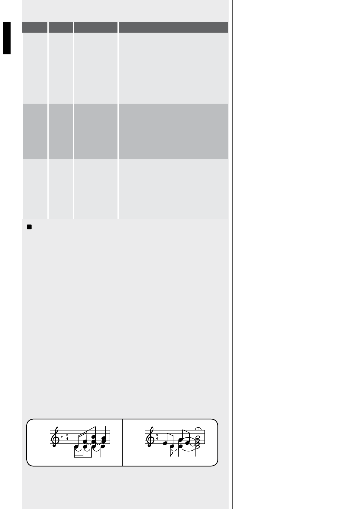
32
FRANÇAIS
i
Le commutateur DIP n°2 (groupe de 8 commutateurs DIP) vous permet de permuter le
niveau de priorité des canaux 1 et 2. Cette configuration ne fonctionne pas en mode de
priorité inter-verrouillé.
Dès qu’un évènement prioritaire prend fin, l’état initial est restauré (les canaux 1, 2, 3, 4 et
l’entrée auxiliaire sélectionnée sont mixés, sauf si un autre évènement prioritaire est en cours).
Permet de répéter continuellement le carillon (court ou long selon la position du commutateur
DIP n°8, voir 20). Cet ordre possède le niveau de priorité maximal et supprime toujours
l’entrée auxiliaire sélectionnée du signal qui alimente l’amplificateur.
Les commutateurs DIP 5 et 6 (groupe de 8 commutateurs DIP, voir 20) permettent de
sélectionner le mode de priorité pour les canaux 2 et 3 ; vous pouvez choisir entre « Push »
(la priorité est conservée uniquement tant que l’ordre est présent) et « Toggle » (la priorité
est activée/désactivée alternativement à chaque impulsion de l’ordre).
Note : le mode de priorité choisi est appliqué aux deux microphones d’annonce
BM3001
(si présents) et aux ordres prioritaires (des connecteurs amovibles).
Vous pouvez régler chaque gain d’entrée sur le niveau micro (MIC) ou -20 dBu (0 dBu pour le
canal 1). Vous pouvez aussi allumer/éteindre l’alimentation fantôme (PHANTOM), insérer/supprimer
le filtre passe-haut et activer/désactiver le carillon joué à chaque évènement prioritaire.
Le carillon n’est pas joué quand la fonction VOX du canal 1 est utilisée (un ordre prioritaire
est nécessaire pour diffuser le carillon).
Sa mélodie peut être courte ou longue (commutateur DIP n°7 du groupe de 8 commutateurs
DIP, voir 20).
Lorsque le carillon est joué (quelques secondes), l’entrée auxiliaire sélectionnée est
supprimée du signal qui alimente l’amplificateur.
DIP 2 DIP 3 MODE
… I/LCK
INTER-
VERROUILLÉ
Seul le premier ordre prioritaire des canaux 1 à 4
(et également la fonction VOX du canal 1 si elle
a été activée avec le commutateur DIP n°4) est
accepté.
Aucun autre ordre prioritaire ne sera accepté tant
que le précédent ne sera pas supprimé.
Note : le seul évènement qui peut être
activé ultérieurement (et écraser une priorité
précédente) est CHIME SEQUENTIAL COMMAND.
PRIO
IN1
GR.
PRIOR.
PRIORITÉ
GRADUELLE 1
Un ordre prioritaire de niveau supérieur peut écraser
le précédent. Les niveaux de priorité sont :
1. (maximum) CHIME SEQUENTIAL COMMAND
2. canal 1 (y compris VOX)
3. canal 2
4. canal 3
5. canal 4
PRIO
IN2
GR.
PRIOR.
PRIORITÉ
GRADUELLE 2
Un ordre prioritaire de niveau supérieur peut
écraser le précédent. Les niveaux de priorité sont :
1. (maximum) CHIME SEQUENTIAL COMMAND
2. canal 2
3. canal 1 (y compris VOX)
4. canal 3
5. canal 4
SHORT LONG
MODE DE PRIORITÉ PUSH /
TOGGLE DES CANAUX 2 ET 3
CHIME SEQUENTIAL COMMAND
GROUPE DE 4 COMMUTATEURS
DIP (POUR CHAQUE CANAL
1 À 4)
INFORMATIONS RELATIVES
AU CARILLON
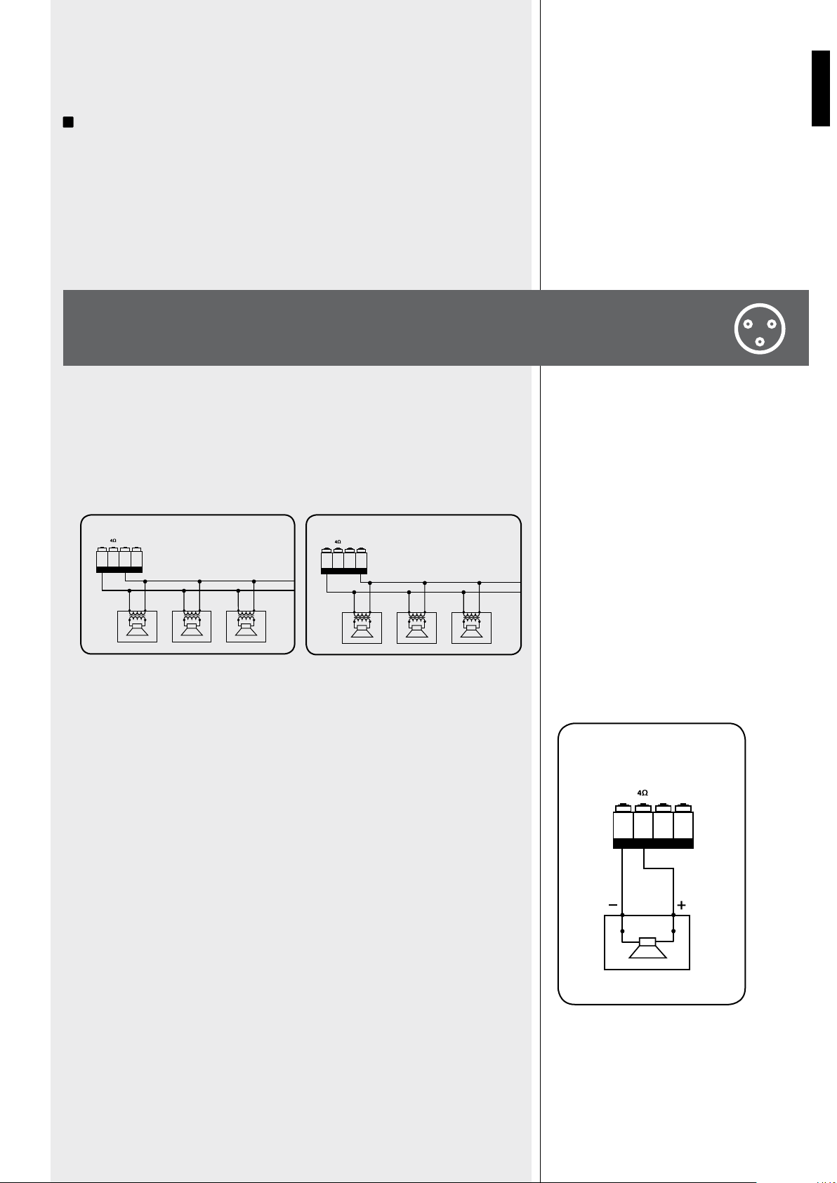
33
FRANÇAIS
Les canaux 2 et 3 possèdent une entrée sur port RJ 45 auquel on peut connecter un
microphone d’annonce BM3001 (note : il faut placer les commutateurs DIP 3 et 4 en mode
« -20 dBu + ALIMENTATION FANTÔME », voir 10, second tableau).
i
Lorsque le microphone d’annonce BM3001 est allumé (prêt à la parole), sa LED
s’allume.
Lorsque le carillon est en cours de diffusion (CHIME est autorisé), le microphone BM3001
est rendu momentanément muet. Le mode de priorité du microphone d’annonce dépend
des réglages mentionnés plus haut.Le microphone d’annonce est rendu muet par les
évènements qui ont un niveau de priorité supérieur (à celui du canal 2 ou 3 auquel le
microphone d’annonce est connecté).
Utilisez une seule sortie – NE MÉLANGEZ PAS LES CONNEXIONS 100 / 70 V et
4 Ω !
- Chaque enceinte doit posséder un transformateur ligne avec un voltage d’entrée égal
au voltage de la ligne (100 ou 70 V).
- La puissance totale des enceintes ne doit pas excéder la puissance maximale de
l’amplificateur.
- L’impédance totale des enceintes ne doit pas être inférieure à 4 Ω. Note : une impédance
totale de 4 Ω permet à l’amplificateur de développer sa puissance maximale. Une
impédance supérieure conduit à une réduction de la puissance fournie par l’amplificateur
(par exemple 8 Ω : environ ½ de la puissance, 16 Ω : environ ¼ de la puissance).
Une impédance inférieure à 4 Ω surcharge l’amplificateur.Loudspeaker models shall be
chosen by considering the max. power (AM 2160: 160 W on a 4 Ω load; AM 2320: 320
W on a 4 Ω load) that the amplifier can deliver.
- Les modèles d’enceintes doivent être choisis en tenant compte de la puissance maximale
(AM 2160 : 160 watts sous 4 Ω ; AM 2320 : 320 watts sous 4 Ω) que l’amplificateur
peut développer.
- La ligne d’enceintes doit être aussi courte que possible ; les câbles longs doivent
posséder une grosse section.
- N’utilisez pas simultanément la sortie à basse impédance (4 Ω) et la sortie à voltage
constant (70 V ou 100 V) sans quoi l’amplificateur sera en surcharge.
100V0
POWER OUTPUT
100V70VCOM
100V0 100V0
100 V
70V0
POWER OUTPUT
100V70VCO M
70V0 70V0
70 V
POWER OUTPUT
100V70VCOM
CONNEXION
DES ENCEINTES
MICROPHONE D’ANNONCE
RCF BM3001 (NON FOURNI)
SORTIES 70 / 100 V À VOLTAGE
CONSTANT
SORTIE À BASSE IMPÉDANCE
(4 Ω)
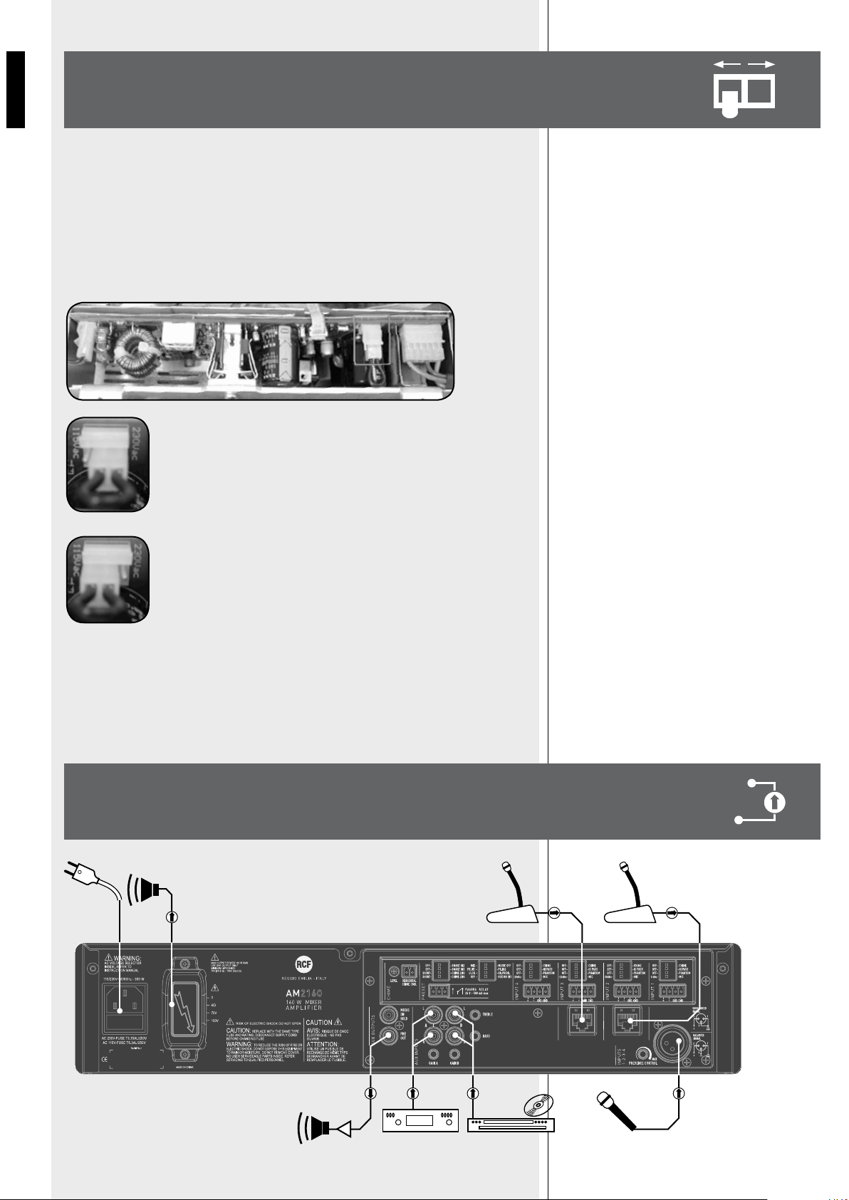
34
FRANÇAIS
IMPORTANT : cette section du manuel s’adresse exclusivement à du personnel
qualifié. Les instructions suivantes doivent être ignorées par l’utilisateur du
produit.
Assurez-vous que l’appareil n’est pas branché au secteur (débranchez le cordon secteur).
Retirez le capot de l’appareil.
Le connecteur permettant de modifier le voltage est encadré par un rectangle.
Si la tension secteur est 230 volts, placez le connecteur en position
230Vac (voir image 2) en respectant les indications inscrites sur le
circuit imprimé (en regardant le connecteur de face, la broche centrale
est connectée à la broche droite).
Si la tension secteur est 115 volts, placez le connecteur en position
115Vac (voir image 3) en respectant les indications inscrites sur le
circuit imprimé (en regardant le connecteur de face, la broche centrale
est connectée à la broche gauche).
Replacez le couvercle de l’appareil.
Avant de brancher l’appareil à la tension secteur, assurez-vous que le fusible à l’intérieur du
connecteur secteur IEC du panneau arrière (voir 25) possède des valeurs adaptées à votre
tension secteur (lisez les indications concernant le fusible sous le connecteur).
MODIFIER
LE VOLTAGE
EXEMPLE
DE CONNEXION
BM 3001 BM 3001
CD/DVDCD/DVD
230V
115V

35
FRANÇAIS
SPÉCIFICATIONS
µ
÷
±
AMPLIFICATEUR
Puissance de sortie (RMS)
Réponse en fréquence
RAPPORT SIGNAL/BRUIT
Canaux 1 ÷ 4
Auxiliaires
Distorsion (à 1 kHz, puissance nominale)
ÉGALISEUR DES ENTRÉES AUX INPUT
Bass
Treble
Réglage PRESENCE (entrées 1 à 4)
Filtre passe-haut (entrées 1 à 4)
SENSIBILITÉ / IMPÉDANCE D’ENTRÉE
MICRO (canaux 1 à 4)
-20 dBu (canaux 2 à 4)
0 dBu (Canal 1)
ENTRÉ AUXILIAIRES (A et B)
Niveau / impédance des sorties auxiliaires
(pre / music on hold)
Voltage/intensité du courant de l’alimentation fantôme
SORTIES HAUT-PARLEUR
Basse impédance
Voltage constant (AM 2160)
Voltage constant (AM 2320)
PROTECTIONS
Amplificateur
Alimentation électrique
GÉNÉRALITÉS
Tension secteur
Consommation d’énergie
Dimensions (l, h, p)
Poids net
160 W (AM 2160), 320 W (AM 2320)
50 Hz ÷ 13.5 kHz
60 dB
80 dB
< 0.3 %
± 8 dB @ 80 Hz
± 8 dB @ 13 kHz
+ 10 dB @ 2.15 kHz
150 Hz
Symétrique, – 56 dBu (max – 25 dBu ) / 10 kΩ
Symétrique, – 28 dBu (max 0 dBu) / 5 kΩ
Symétrique, – 7 dBu (max + 19 dBu) / 10 kΩ
Réglables – 4 ÷ + 15 dBu (max +22 dBu) / 20 kΩ
– 1 dBu / 600 Ω
32 V / 18 mA
4 Ω
70 V (31 Ω) / 100 V (62 Ω)
70V (16 Ω) / 100 V (31 Ω)
Surcharge, court-circuit, thermique
Alimentation électrique, Fusibles
115-230V / 50-60 Hz
350 W (AM 2160), 600 W (AM 2320)
442 mm, 88 mm, 230 mm (2U 19” rack)
4.8 kg (AM 2160), 6.2 kg (AM 2320)

36
DEUTSCH
Bevor Sie dieses Gerät in Betrieb nehmen, lesen Sie die Bedienungsanleitung bitte sorgfältig
durch und halten Sie diese zur weiteren Einsichtnahme bereit. Die Bedienungsanleitung
sollte als wesentlicher Bestandteil dieses Produkts verstanden werden und sollte
diesem entsprechend immer beiliegen (auch wenn das Gerät den Besitzer wechselt), um
eine korrekte Installation und Benutzung zu gewährleisten sowie um als Referenz für
Sicherheitsvorkehrungen zu dienen.
R.C.F S.p.A. übernimmt keine Haftung im Falle einer unsachgemäßen Installation und/ oder
Benutzung dieses Produkts.
WARNUNG: Um die Gefahr eines Brandes oder eines Stromschlags auszuschließen, setzen
Sie dieses Produkt niemals Regen oder sonstiger Feuchtigkeit aus.
SICHERHEITSHINWEISE
1. Alle Anweisungen, im Besonderen die sicherheitsrelevanten, sollten mit besonderer
Aufmerksamkeit gelesen werden, da sie entscheidende Informationen enthalten.
2. HAUPTSTROMVERSORGUNG
a. Netzspannung kann tödlich sein. Lassen Sie bei Einbau und Anschluss dieses Produkts
deshalb den Netzschalter ausgeschaltet.
b. Stellen Sie vor dem Einschalten sicher, dass das Gerät korrekt angeschlossen ist und
die auf dem Typenschild Ihres Geräts vermerkte Netzspannung mit der am Einsatzort
übereinstimmt. Sollte letzteres nicht der Fall sein, treten Sie diesbezüglich bitte mit
Ihrem RCF-Händler in Kontakt.
c. Die äußeren Metallteile Ihres Geräts sind durch den Schutzleiter des Netzkabels
geerdet. Als Produkt der SCHUTZKLASSE I muss das Gerät deshalb an einem mit
Schutzerde ausgestatteten Netzanschluss betrieben werden.
d. Schützen Sie das Netzkabel vor Beschädigung. Verlegen Sie es so, dass niemand
darauf treten kann und keinerlei Gegenstände es verletzen können.
e. Zur Vermeidung elektrischer Schläge öffnen Sie das Produkt nie: im Inneren sind keine
vom Benutzer zu bedienenden Teile.
Stellen Sie sicher, dass keine Gegenstände oder Flüssigkeiten ins Innere des Gerätes
gelangen können, da dies zu einem Kurzschluss führen kann. Schützen Sie das Gerät vor
Tropf- und Spritzwasser. Stellen Sie keine mit Flüssigkeit gefüllten Behälter (z.B. Vasen) oder
offene Brandquellen (z.B. Kerzen) auf das Gerät.
4. Versuchen Sie niemals Funktionen, Modifikationen oder Reparaturen am Gerät
durchzuführen, die nicht ausdrücklich in dieser Bedienungsanleitung beschrieben werden.
Kontaktieren Sie Ihr autorisiertes Service-Center oder qualifiziertes Fachpersonal, sollte
eines der folgenden Ereignisse auftreten:
- Das Gerät funktioniert nicht (oder funktioniert nicht korrekt)
- Das Netzkabel wurde beschädigt
- Gegenstände oder Flüssigkeiten sind ins Innere des Gerätes gelangt
- Das Produkt war einer hohen Belastung/ einem heftigen Stoß ausgesetzt.
5. Wenn Sie dieses Produkt für einen längeren Zeitraum nicht benutzen, ziehen Sie den
Netzstecker.
6. Wenn ungewöhnliche Gerüche oder Rauch von diesem Produkt ausgehen, schalten Sie
es unverzüglich aus und ziehen Sie den Netzstecker.
7. An den mit dem Symbol
gekennzeichneten Anschlüssen liegt GEFÄHRLICHE
NETZSPANNUNG (Phasenleiter) an, und diese sind entweder von einer entsprechend
QUALIFIZIERTEN PERSON anzuschließen, oder ein vorgefertigtes Netzkabel ist zu
benutzen.
WICHTIGER
HINWEISE
WICHTIGER HINWEIS
WARNUNG

37
ITALIANO
8. Schließen Sie dieses Produkt nicht an Ihnen unbekannte Geräte oder Ihnen unbekanntes
Zubehör an.
Um Herabfallen auszuschließen, stapeln Sie Geräte nur dann, wenn die Bedienungsanleitung
dies ausdrücklich zulässt.
9. RCF S.p.A. empfiehlt dringend, dass dieses Produkt nur beruflich qualifizierte
Fachkräfte (oder spezialisierte Firmen) installieren, welche die korrekte
Anbringung sicherstellen und diese in Übereinstimmung mit den jeweiligen
Gesetzen zertifizieren können.
Die gesamte Audioanlage muss in Übereinstimmung mit den aktuellen
Standards und Bestimmungen für elektrische Anlagen stehen.
10. Racks und Transportwagen
Für dieses Gerät sollten – wenn notwendig – nur vom Hersteller für diesen Zweck
empfohlene Racks beziehungsweise Transportwagen zum Einsatz kommen, die dann mit
entsprechender Vorsicht zu bewegen sind. Plötzliches Anhalten, übermäßige Schubkraft
oder unebener Boden können zum Umkippen führen.
11. Bei der Installation einer professionellen Audioanlage sind zahlreiche mechanische
und elektrische Randbedingungen zu beachten (zusätzlich zu den rein akustischen, wie
Schalldruck, Abstrahlwinkelbereich, Frequenzgang etc.).
12. Gehörverlust
Hohe Schallpegel können permanenten Gehörverlust zur Folge haben. Der zu Gehörverlust
führende Schalldruck unterscheidet sich von Person zu Person und hängt von der
Einwirkungsdauer ab. Um zu vermeiden, möglicherweise gefährlich hohen Schalldrücken
ausgesetzt zu sein, sollte jeder, der sich im Bereich solcher Pegel befinden, angemessenen
Gehörschutz verwenden.
Bei Benutzung eines Lautsprechers, der hohe Schalldrücke liefern kann, ist deshalb das
Tragen von Ohrstöpseln oder eines Kopfhörers erforderlich.
Der maximale Schalldruck des Lautsprechersystems ist in dessen Bedienungsanleitung bei
den technischen Daten angegeben.
WICHTIGE HINWEISE
Zur Vermeidung von Störsignalen in Mikrofon- oder Hochpegel- (line-) Kabeln benutzen Sie
nur geschirmte Kabel, und vermeiden Sie deren Nähe zu:
- Geräten, von denen starke elektromagnetische Felder ausgehen (z. B. größeren
Netztransformatoren),
- Netzkabeln,
- Lautsprecherkabeln.
BETRIEBSVORKEHRUNGEN
- Behindern Sie nicht den Luftstrom durch die Lüftungsgitter. Stellen Sie das Gerät nicht in
die Nähe von Wärmequellen, und sorgen Sie auch in der Umgebung der Lüftungsgitter
immer für ausreichende Luftzirkulation.
- Übersteuern Sie das Produkt nicht für längere Zeit.
- Betätigen Sie die Bedienelemente (Schalter, Drehknöpfe, etc.) nie mit übermäßiger
Kraft.
- Benutzen Sie keine Lösemittel, Alkohol, Benzin oder andere flüchtige Substanzen zur
Reinigung der Außenteile dieses Produkts.
WICHTIGER HINWEIS
BETRIEBSVORKEHRUNGEN
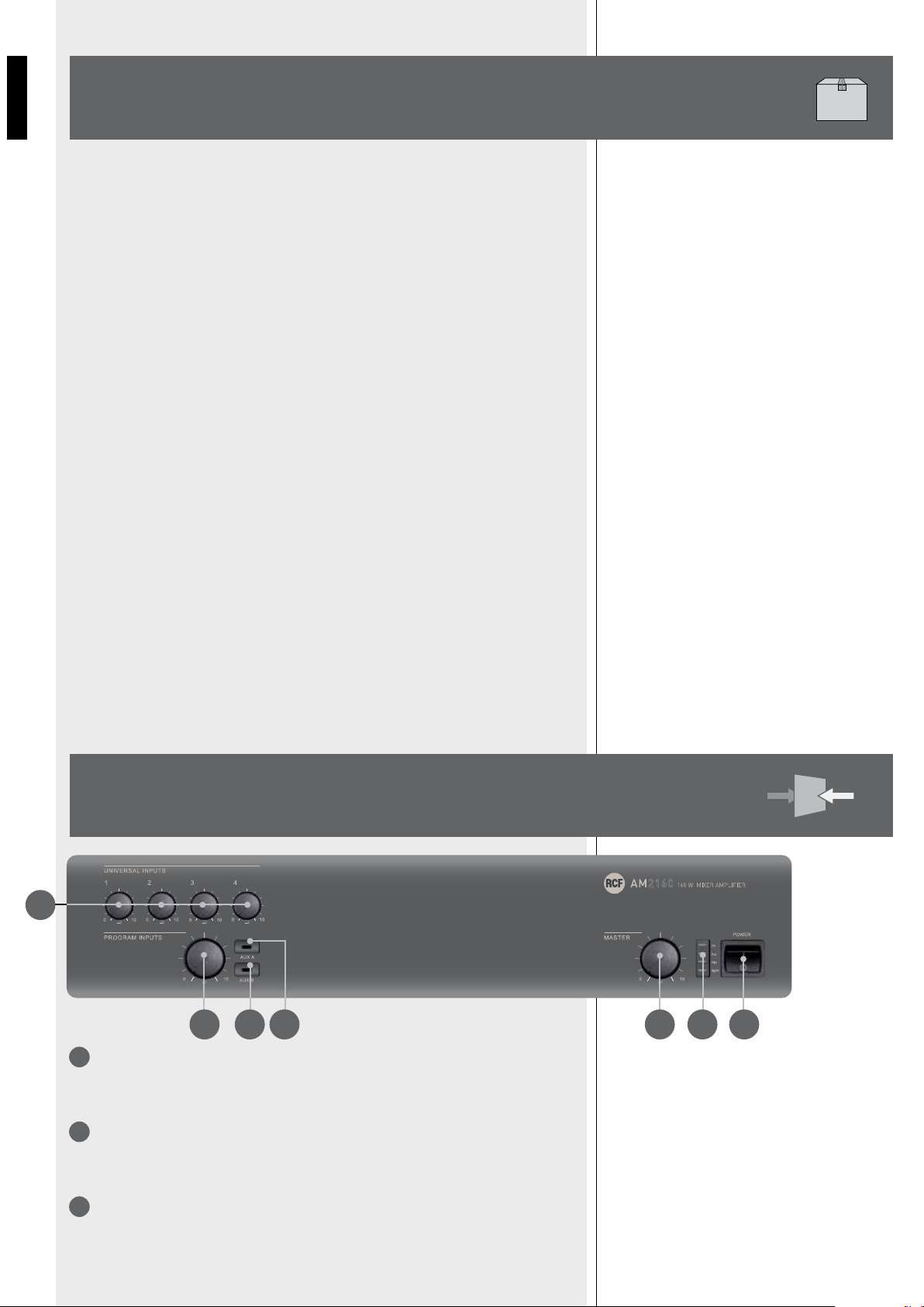
38
DEUTSCH
RCF S. p. A. dankt Ihnen für den Erwerb dieses Produkts, dessen Konstruktion
Zuverlässigkeit und hohe Wiedergabeleistung garantiert.
Der AM2160 und AM2320 sind Mischverstärker mit vier Mikrofon- / Hochpegeleingängen
1, 2, 3, und 4 in Form von Schraubleisten (der erste hat auch eine XLR-Buchse) und zwei
„aux inputs“ A und B für Musikquellen (z. B. CD-Spieler, Tuner etc.).
Die beiden Modelle haben identische Eigenschaften bis auf ihre maximale Ausgangsleistung
von 160 W (AM2160) bzw. 320 W (AM2320). Die Verstärker besitzen einen Ausgang für
niederohmige Lautsprecher (min. 4 Ω) und einen ELA-Ausgang (100 V / 70 V, zum Betrieb
von Lautsprechern mit entsprechenden Transformatoren).
Eingang 1 verfügt über eine Schaltung zur Signalerkennung („VOX“), die ihm – wenn
aktiviert – automatisch Vorrang („PRIORITY“) gewährt. Außerdem können alle Eingänge
1, 2, 3 und 4 Vorrang erlangen durch eine externe, an den entsprechenden Kontakt der
Schraubleiste angelegte Vorranganforderung. Eingänge 2 und 3 besitzen zusätzlich eine
RJ45-Buchse für den schnellen Anschluss des Durchsagemikrofons RCF BM 3001 (mit
einem CAT5-Kabel), das bereits eine Vorrangtaste besitzt.
Der Ausgang „MUSIC ON HOLD“ erlaubt es, die Musik (das Ausgangssignal des an den
Eingang „AUX INPUT A“ angeschlossenen Geräts) an weitere Verstärker, Mischpulte,
Telefonanlagen (Funktion „Music On Hold“) etc. zu schicken.
Die vier Mikrofon- / Hochpegeleingänge 1 bis 4 haben einen gemeinsamen Präsenzregler
und separate Hochpassfilter, welche zur Verbesserung der Sprachverständlichkeit dienen
können. Unabhängig davon verfügen die beiden Aux-Eingänge A und B über eine
Klangregelung (für beide Eingänge gemeinsam).
Leuchtdioden an der Frontplatte zeigen den Betriebszustand des Geräts (ON, PROT), die
Aktivierung des Vorrangs (PRIOR) und das Anliegen eines Signal- / Spitzenpegels (SIG/PK) an.
SEPARATE LAUTSTÄRKEREGLER FÜR DIE UNIVERSALEINGÄNGE (1, 2, 3, 4).
Bemerkung: für unbenutzte Eingänge sollten diese stets ganz gegen den Uhrzeigersinn
zurückgedreht sein (auf 0).
GEMEINSAMER LAUTSTÄRKEREGLER FÜR DIE AUX-EINGÄNGE.
Bemerkung: drehen Sie ihn ganz gegen den Uhrzeigersinn zurück (auf 0), wenn Sie keinen
AUX-Eingang benutzen.
„AUX A“-TASTE (mit LED).
Sie verbindet (LED leuchtet) den AUX INPUT A mit dem internen Verstärker (und dem
Ausgang „PRE OUT“) beziehungsweise trennt ihn davon.
GERÄTEBESCHREIBUNG
2
3
1
FRONTPLATTE
1
2 4 3 5 6 7
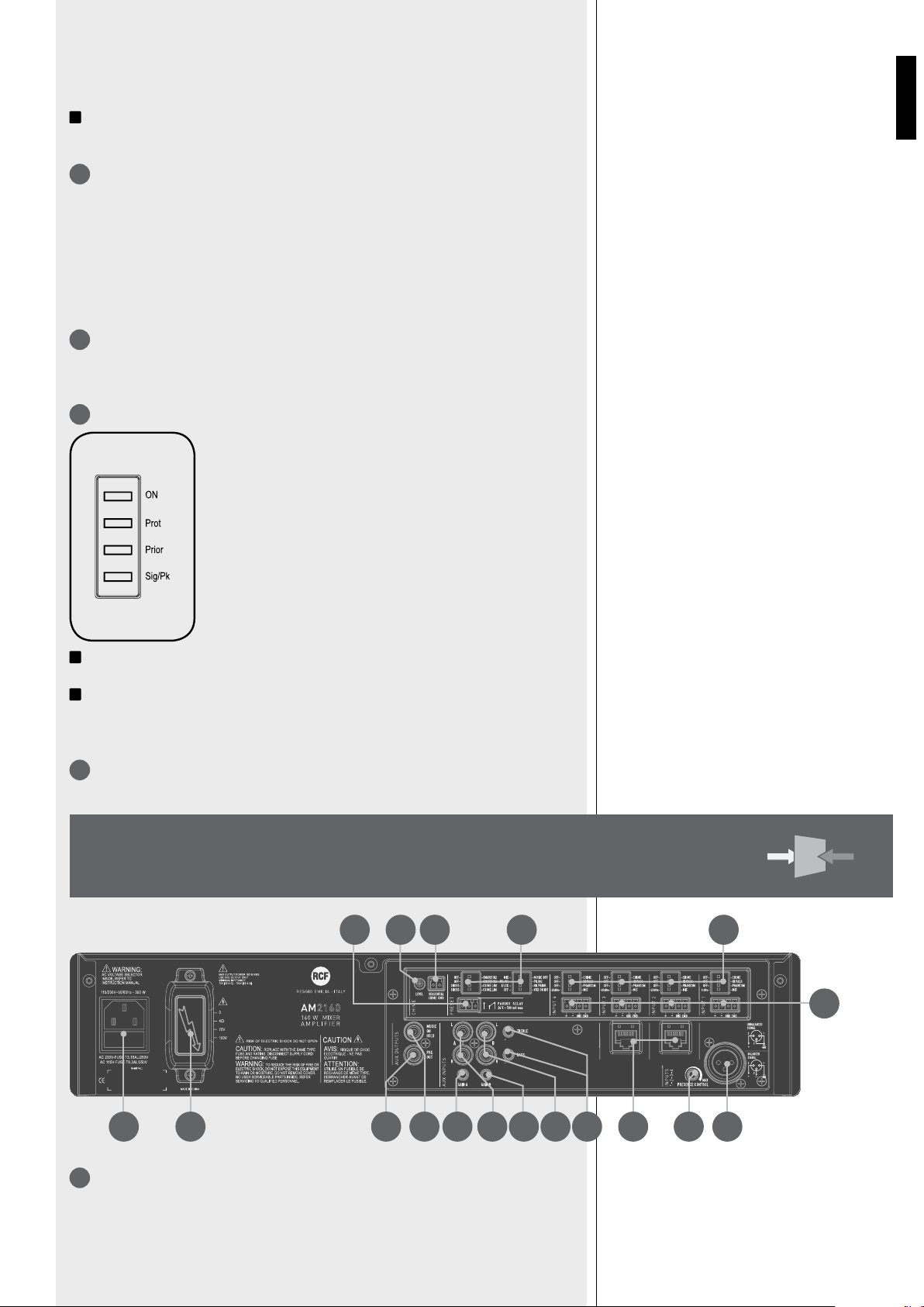
39
DEUTSCH
Die beiden AUX-Eingänge A und B lassen sich nicht zugleich betreiben: im eingeschalteten
Zustand ist AUX INPUT B vom Verstärker getrennt (LED „AUX B“ leuchtet nicht).
i
Das Signal von AUX INPUT A liegt immer am Ausgang „MUSIC ON HOLD“ (unbeeinflusst
von den Tasten AUX A und AUX B).
„AUX B“-TASTE (mit LED).
Sie verbindet (LED leuchtet) den AUX INPUT B mit dem internen Verstärker (und dem
Ausgang „PRE OUT“) beziehungsweise trennt ihn davon.
Die beiden AUX-Eingänge A und B lassen sich nicht zugleich betreiben: im eingeschalteten
Zustand ist AUX INPUT A vom Verstärker getrennt (LED „AUX A“ leuchtet nicht).
Es dauert 10 Sekunden (nach dem Drücken der Taste AUX A oder AUX B), bis der interne
Speicher die letzte Einstellung übernimmt.
MASTER-LAUTSTÄRKEREGLER DES INTERNEN VERSTÄRKERS.
Bemerkung: die beiden Cinch-Ausgänge („PRE OUT“ und „MUSIC ON HOLD“) sind vom
MASTER-Lautstärkeregler unbeeinflusst.
LEUCHTDIODEN.
ON grün: das Gerät ist eingeschaltet
PROT rot: Übersteuerungssicherung
orange: Übertemperatursicherung
PRIOR gelb: Vorrang eines Eingangs, entweder durch die
Funktion „VOX“ oder durch eine Vorranganforderung an
einem der Universaleingänge 1 bis 4 oder durch ein „CHIME
SEQUENTIAL COMMAND“.
SIG/PK grün: der Signalpegel ist höher als –15 dB
grün + rot: der Signalpegel ist zwischen 0 dB und +2 dB
rot (peak): der Signalpegel ist größer als oder gleich +3 dB
i
0 dB = Signalpegel, der zur Maximalleistung des Verstärkers führt.
i
Die interne Limiter-Schaltung hilft, Übersteuerungen zu vermeiden, aber es ist trotzdem
empfehlenswert, „Master Volume“ (oder den Lautstärkeregler eines einzelnen Kanals, dessen
Pegel zu hoch ist) zurückzudrehen, wenn die „Sig/Pk“-LED kontinuierlich rot leuchtet.
NETZSCHALTER (POWER, 0 = AUS, I = AN).
ZWEI RJ45-BUCHSEN (Kanäle 2 und 3) zum Anschluss je eines Durchsagemikrofons
RCF BM 3001.
Bemerkung: wenn ein Durchsagemikrofon BM 3001 angeschlossen ist, müssen die Kanal-DIP-
Schalter 3 und 4 auf die Betriebsart „–20 dBu + PHANTOM“ gestellt sein (siehe unten, 10).
7
8
4
5
6
RÜCKSEITE
9
1020222123
25 24 18 19 15 14 17 16 13 8 12 11
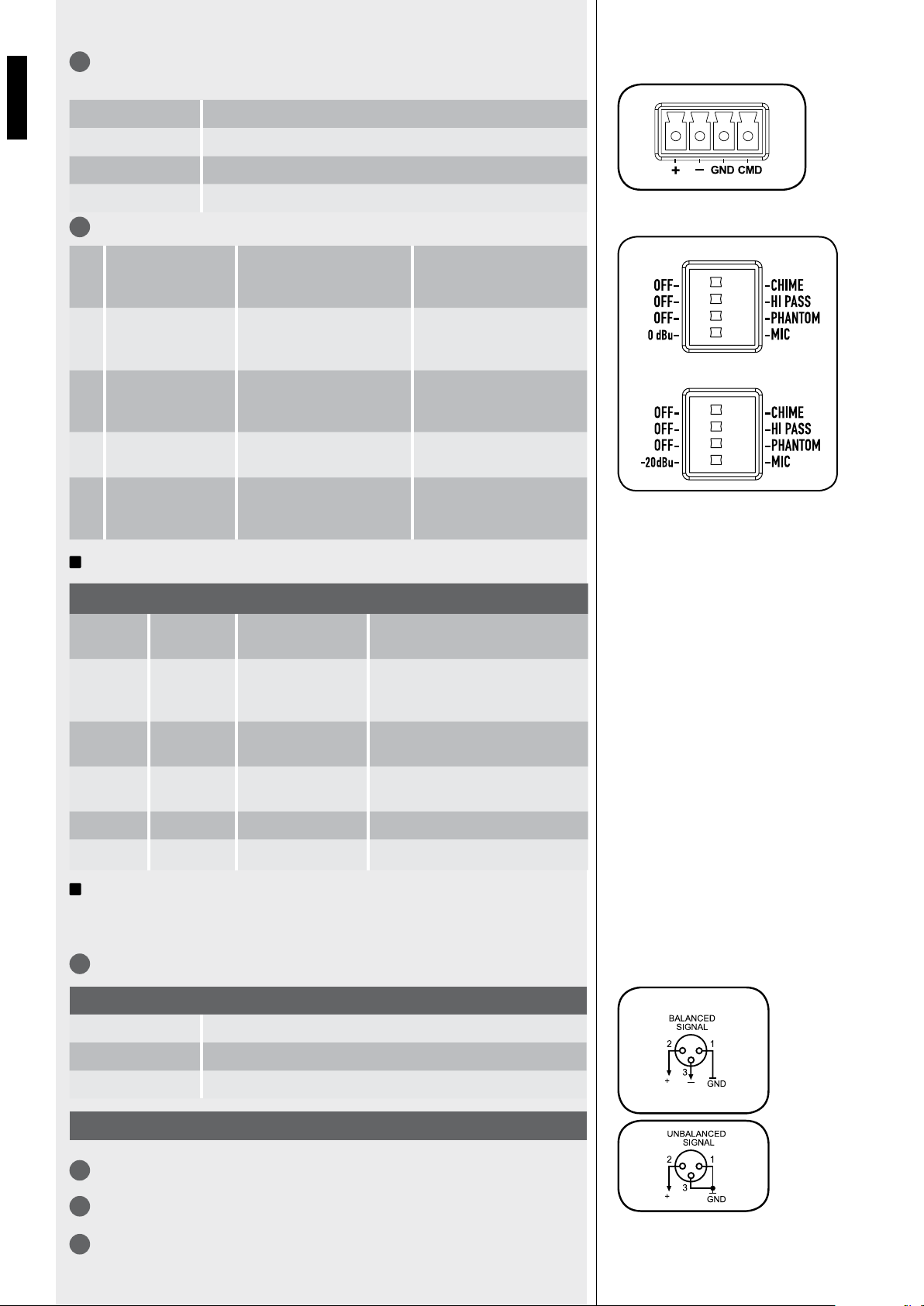
40
DEUTSCH
9
VIER SYMMETRISCHE SIGNALEINGÄNGE (Kanäle 1, 2, 3, 4) mit Schraubleisten-
Anschlüssen.
JEDER DER VIER KANÄLE HAT VIER DIP-SCHALTER.
i
Beispiele für Einstellungen der Kanal-DIP-Schalter 3 und 4:
i
Bei Benutzung eines Durchsagemikrofons BM 3001 ist es notwendig, im entsprechenden
Kanal (2, 3) die Betriebsart „–20 dBu + PHANTOM“ zu wählen (Kanal-DIP-Schalter 3 auf
PHANTOM, Kanal-DIP-Schalter 4 auf –20 dBu).
XLR-ANSCHLUSSBUCHSE FÜR KANAL 1.
PRÄSENZREGLER (f = 2,15 kHz), GEMEINSAM FÜR KANÄLE 1, 2, 3, 4.
HÖHEN-UND BASSREGLER, GEMEINSAM FÜR AUX INPUT A UND B.
EINGANG DES AUX INPUT A MIT ZWEI CINCH-BUCHSEN.
+
Nichtinvertierender Audioeingang
–
Invertierender Audioeingang
GND
Masse (Abschirmung)
CMD
Vorranganforderung (aktiv, wenn mit GND verbunden)
SYMMETRISCHER ANSCHLUSS
+ nichtinvertiert
- invertiert
GND Abschirmung
UNSYMMETRISCHER ANSCHLUSS
IN 1
IN 2-3-4
DIP 3 DIP 4
BETRIEBSART ANWENDUNG (BEISPIELE)
OFF 0 dBu
0 dBu
(Kanal 1)
CD- / MP3-Spieler, Tuner,
Sprachspeicher, Telefonanlage.
PHANTOM 0 dBu
0 dBu + PHANTOM
(KANAL 1)
Vorverstärktes (Pegel 0 dBu)
Durchsagemikrofon, das
Phantomspeisung benötigt.
OFF -20 dBu
–20 dBu
(KANÄLE 2, 3, 4)
Audioquelle mit einem Ausgangspegel
von –20 dBu.
PHANTOM -20 dBu
–20 dBu + PHANTOM
(KANÄLE 2, 3, 4)
Durchsagemikrofon BM 3001 (Kanäle
2, 3).
OFF MIC MIC.
Dynamisches Mikrofon.
PHANTOM MIC MIC + PHANTOM.
Elektret-Kondensatormikrofon.
1 OFF – CHIME
OFF: die Gongfunktion ist
deaktiviert.
CHIME: die Gongmelodie
ertönt, sobald eine
Vorranganforderung anliegt.
2 OFF – HI PASS
OFF: das Hochpassfilter befindet
sich nicht im Signalweg (flacher
Frequenzgang).
HIGH PASS: das Hochpassfilter
befindet sich im Signalweg.
3 OFF – PHANTOM
OFF: die Phantomspeisung für
diesen Kanal ist ausgeschaltet.
PHANTOM: die Phantomspeisung
für ein Kondensatormikrofon ist
angeschaltet.
4 CHANNEL 1
0 dBu – MIC
0 dBu: Eingangsempfindlichkeit
0 dBu (775 mV).
MIC: Eingangsempfindlichkeit
auf Mikrofonpegel.
5 CHANNELS 2, 3, 4
-20 dBu – MIC
–20 dBu:
Eingangsempfindlichkeit –20
dBu (78 mV).
MIC: Eingangsempfindlichkeit
auf Mikrofonpegel.
10
11
12
13
14

41
DEUTSCH
i
Der Verstärker addiert die beiden Kanäle einer an den AUX INPUT A angeschlossenen
Stereoquelle intern (zu einem Monosignal); dies gilt auch für eine an AUX INPUT B
angeschlossene Stereoquelle.
GAIN-REGLER (EINGANGSEMPFINDLICHKEIT) FÜR DEN AUX INPUT A.
EINGANG DES AUX INPUT B MIT ZWEI CINCH-BUCHSEN.
GAIN-REGLER (EINGANGSEMPFINDLICHKEIT) FÜR DEN AUX INPUT B.
SIGNALAUSGANG „PRE OUT“ (mit einer Cinch-Buchse), der das am Eingang des
internen Verstärkers liegende Signal ausgibt (entweder das eines einzelnen, durch die
Vorrangfunktion (PRIORITY) bestimmten Kanals oder eine Mischung aller Kanäle 1, 2, 3
und 4 sowie des gewählten AUX INPUT).
i
|i| Benutzen Sie PRE OUT für den Anschluss eines weiteren, externen Verstärkers.
SIGNALAUSGANG „MUSIC ON HOLD“ (MIT EINER CINCH-BUCHSE), DER EIN
MONOSIGNAL DER AN AUX INPUT A ANGESCHLOSSENEN QUELLE AUSGIBT.
i
Der Ausgang „MUSIC ON HOLD“ (für ein an den Eingang „AUX INPUT A“ angeschlossenes
Gerät) ist für den Anschluss an eine Telefonanlage mit der Funktion „Music On Hold“
vorgesehen.
ACHT VORRANG-DIP-SCHALTER ZUR WAHL DER EINSTELLUNGEN FÜR DIE
VORRANGANFORDERUNG (PRIORITY):
19
20
1.
MIX –
MUSIC OFF
MIX: das Signal des gewählten AUX
INPUT ist immer im (gemischten)
Verstärkersignal enthalten, sogar
während eines Vorrangs.
MUSIC OFF: besteht ein Vorrang,
gelangt das Signal des gewählten
AUX INPUT nicht zum Verstärker.
2.
PRIO INPUT 1
PRIO INPUT 2
PR. IN1: Kanal 1 hat die höchste
Priorität (außer bei „CHIME
SEQUENTIAL COMMAND“)
bei Vorranganforderung (oder
VOX), wenn DIP-Schalter 3 auf
„graduated priority“ steht.
PR. IN2: Kanal 2 hat die höchste
Priorität (außer bei „CHIME
SEQUENTIAL COMMAND“) bei
Vorranganforderung, wenn DIP-
Schalter 3 auf „graduated priority“
steht.
3.
I/LCK –
GR. PRIOR.
I/LCK: „Interlock“-Modus,
Unterdrückung nachfolgender
Vorranganforderungen (siehe
Abschnitt „Bedienung“).
GR. PRIOR: gestufte Vorrangfolge
gemäß obigem Schalter 2 (siehe
auch Abschnitt „Bedienung“).
4.
OFF –
VOX ON IN1
OFF: die VOX-Funktion von Kanal 1
ist ausgeschaltet.
VOX ON IN1: die VOX-Funktion
von Kanal 1 ist aktiv (automatische
Vorranganforderung, wenn die
Schaltung ein Signal an Eingang 1
detektiert).
5.
OFF –
SMART IN2
OFF: ein Vorrang für Kanal 2 besteht
nur, solange das entsprechende
Signal für Vorranganforderung
andauert (Haltemodus).
SMART IN2: Die Priorität für Kanal
2 wird durch jeden Impuls des
entsprechenden Befehls ein- bzw. /
ausgeschaltet („Toggle-Modus“).
6.
OFF –
SMART IN3
OFF: ein Vorrang für Kanal 3 besteht
nur, solange das entsprechende
Signal für Vorranganforderung
andauert (Haltemodus).
SMART IN3: Die Priorität für Kanal
3 wird durch jeden Impuls des
entsprechenden Befehls ein- bzw. /
ausgeschaltet („Toggle-Modus“).
7.
SHORT –
CHIME LNG
SHORT: kurze Gongmelodie
bei Vorranganforderung von
entsprechend eingestelltem (DIP 1
des Kanals) Kanal.
CHIME LNG: lange Gongmelodie
bei Vorranganforderung von
entsprechend eingestelltem (DIP 1
des Kanals) Kanal.
8.
SHORT –
CHIME LNG
SHORT: bei einem „CHIME
SEQUENTIAL COMMAND“ ertönt
die kurze Gongmelodie kontinuierlich.
CHIME LNG: bei einem „CHIME
SEQUENTIAL COMMAND“ ertönt
die lange Gongmelodie kontinuierlich.
15
16
17
18
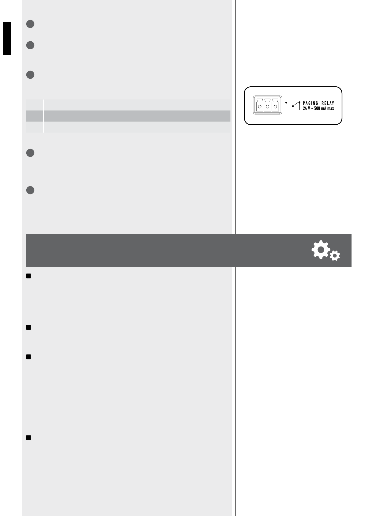
42
DEUTSCH
1 2 3
CHIME LEVEL, GONGLAUTSTÄRKE (TRIMMER MIT KLEINEM SCHRAUBENDREHER
EINSTELLBAR).
EINGANG FÜR CHIME SEQUENTIAL COMMAND MIT SCHRAUBLEISTE (aktiv, wenn die
beiden Anschlüsse miteinander verbunden sind), um die Gongmelodie kontinuierlich ertönen
zu lassen (die Gongmelodie ist mit Vorrang-DIP-Schalter 8 einstellbar, siehe 20-8).
KONTAKTE DES DURCHSAGE-RELAIS (PAGING RELAY) MIT DREIPOLIGER
SCHRAUBLEISTE.
Das interne Relais ist angeschaltet, wenn eine Vorranganforderung besteht.
Maximale Spannung an den Kontakten: 24 V; maximaler Strom: 0,5 A
AUSGANG VOM VERSTÄRKER (AM2160: max. 160 W, AM2320: max. 320 W) ZU DEN
LAUTSPRECHERN (ELA-Leitung 100 V / 70 V oder Impedanz 4 Ω).
Benutzen Sie immer nur einen dieser Ausgänge (lesen Sie den Abschnitt
„Lautsprecheranschlüsse“).
KALTGERÄTE-NETZBUCHSE (VDE, IEC) MIT SICHERUNG.
Bevor Sie das Netzkabel anschließen, vergewissern Sie sich, dass die am Gerät eingestellte
Netzspannung (230 V oder 115 V) gleich der des örtlichen Netzes ist.
Hinweis: der Sicherungstyp ist auf der Rückseite vermerkt (unter der Netzbuchse).
i
Die interne „VOX“-Schaltung aktiviert automatisch den Vorrang für Kanal 1, wenn sie
ein Signal an dessen Eingang detektiert.
Wenn kein Vorrang (auch nicht durch „VOX“ oder „CHIME SEQUENTIAL COMMAND“)
besteht, mischt das Gerät die Signale aller Universalkanäle 1, 2, 3 und 4 sowie des
gewählten AUX INPUT (A oder B) zusammen.
i
Die Lautstärke der Musik (von einem CD- / MP3-Spieler, Tuner etc.) hängt sowohl vom
AUX-Lautstärkeregler auf der Frontplatte (siehe 2) als auch vom entsprechenden GAIN-
Regler (siehe 15 und 17) an der Rückseite ab.
i
Die beiden AUX-Eingänge lassen sich durch ihre jeweiligen Tasten (siehe 3 und 4) auf der
Frontplatte aktivieren bzw. stummschalten
VORRANG (PRIORITY)
Für die Dauer eines Vorrangs (oder VOX) kann der gewählte AUX INPUT (A oder B) je
nach Stellung des Vorrang-DIP-Schalters 1 (siehe 20) zum Signal hinzugemischt oder
stummgeschaltet sein.
Besteht ein Vorrang (die „PRIOR“-LED leuchtet), gelangt nur das Signals des diesen Vorrang
hervorrufenden Kanals 1, 2, 3 oder 4 (und gegebenenfalls das des AUX INPUT, siehe oben)
zum Verstärker (und zum Ausgang PRE OUT).
i
Bei aktiviertem CHIME SEQUENTIAL COMMAND ist der gewählte Aux-Eingang während
eines Vorrangs stets vom Signal ausgeschlossen.
Die Betriebsart des Vorrangs und die VOX-Funktion lassen sich durch die Vorrang-DIP-
Schalter 2 und 3 einstellen (siehe 20).
BEDIENUNG
1
Ohne Vorrang offen
2
Gemeinsamer Kontakt
3
Ohne Vorrang geschlossen
21
22
23
24
25
NACH EINSCHALTEN
(ODER NACH ENDE
EINES VORRANGS)
43
DEUTSCH
i
Il dip-switch nr.2 (gruppo di 8 microinterruttori) permette di scambiare il livello di
precedenza tra i canali 1 e 2; questa impostazione non ha effetto nel modo interbloccato.
Der Vorrang-DIP-Schalter 2 erlaubt es, die Wertigkeitsstufen der Kanäle 1 und 2 zu tauschen.
Die Einstellung ist in der Betriebsart „Interlocked“ jedoch wirkungslos.
Das CHIME SEQUENTIAL COMMAND bewirkt eine kontinuierliche Wiederholung des (kurzen
oder langen, je nach Stellung des Vorrang-DIP-Schalters 8, siehe 20) Gongs. Dieser Befehl hat
die höchste Wertigkeitsstufe und schaltet den gewählten Aux-Eingang stets stumm.
Die Vorrang-DIP-Schalter 5 und 6 (siehe 20) erlauben für die Vorranganforderungen der
Kanäle 2 und 3 die Wahl zwischen einem Haltemodus (der Vorrang besteht nur, solange
das entsprechende Signal für Vorranganforderung andauert, Schalter auf OFF) und einem
„Toggle“-Modus (Vorranganforderungen, z. B. durch Drücken der Vorrangtaste, schalten
den Vorrang abwechselnd an und aus, Schalter auf SMART IN 2 / 3).
Bemerkung: der gewählte Vorrangmodus gilt sowohl für Vorranganforderungen vom
Durchsagemikrofon BM 3001 (sofern vorhanden) als auch für solche an der Schraubleiste (9).
Die Eingangsempfindlichkeit jedes der Universalkanäle 1-4 lässt sich entweder auf Mikrofonpegel
(Stellung MIC) oder auf –20 dBu (bzw. 0 dBu für Kanal 1) stellen. Es ist außerdem möglich, die
Phantomspeisung für Kondensatormikrofone ein- oder auszuschalten, das Hochpassfilter in den
Signalweg zu schalten oder daraus zu entfernen und das Abspielen der Gongmelodie bei jeder
Vorranganforderung (CHIME) zu aktivieren oder deaktivieren (siehe 10).
Der Gong ertönt nicht bei Inkrafttreten der VOX-Funktion von Kanal 1 (eine externe
Vorranganforderung ist zum Abspielen der Gongmelodie notwendig).
Die Melodie kann entweder kurz oder lang sein (Vorrang-DIP-Schalter 7, siehe 20).
(Notenbild des kurzen Gongs) (Notenbild des langen Gongs)
Während die Gongmelodie ertönt, gelangt das Signal des gewählten AUX-Input nicht zum
Verstärker.
DIP 2 DIP 3 BETRIEBSART
… I/LCK INTERLOCKED
Nur die zuerst eintreffende Vorranganforderung
von Kanal 1-4 (ebenso Vox von Kanal 1, wenn
mit Vorrang-DIP-Schalter 4 ermöglicht) hat
Gültigkeit.
Jegliche nachfolgend eintreffende
Vorranganforderung hat erst Gültigkeit, wenn die
vorherige endet.
Bemerkung: das einzige nachfolgend aktivierbare
Ereignis (das auch einen vorherigen Vorrang
außer Kraft setzen kann) ist ein CHIME
SEQUENTIAL COMMAND.
PRIO
IN1
GR.
PRIOR.
GRADUATED
PRIORITY 1
Eine Vorranganforderung von höherer Wertigkeit
kann eine noch bestehende vorherige außer Kraft
setzen. Die Wertigkeitsstufen sind:
1. (höchste) CHIME SEQUENTIAL COMMAND
2. Kanal 1 (inklusive VOX)
3. Kanal 2
4. Kanal 3
5. Kanal 4
PRIO
IN2
GR.
PRIOR.
GRADUATED
PRIORITY 2
Eine Vorranganforderung von höherer Wertigkeit kann
eine noch bestehende vorherige außer Kraft setzen.
Die Wertigkeitsstufen sind:
1. (höchste) CHIME SEQUENTIAL COMMAND
2. Kanal 2
3. Kanal 1 (inklusive VOX)
4. Kanal 3
5. Kanal 4
SHORT LONG
CHIME SEQUENTIAL COMMAND
(KONTINUIERLICHER GONG)
HALTE- / „TOGGLE“-
VORRANGMODUS FÜR KANÄLE
2 UND 3
DIE VIER KANAL-DIP-SCHALTER
(PRO KANAL 1-4)
INFORMATIONEN
ÜBER DEN GONG
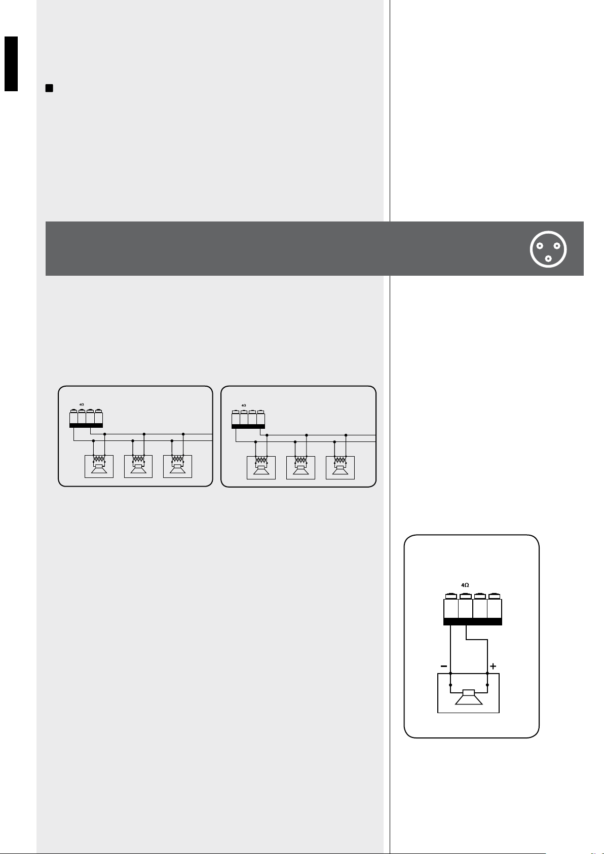
44
DEUTSCH
Eingänge 2 und 3 besitzen zusätzlich eine RJ45-Buchse für den Anschluss eines
Durchsagemikrofons RCF BM 3001 (Bemerkung: die Kanal-DIP-Schalter 3 und 4 müssen
auf die Betriebsart „–20 dBu + PHANTOM“ gestellt sein, siehe 10).
i
Wenn das Durchsagemikrofon BM 3001 eingeschaltet (bereit für eine Durchsage) ist,
leuchtet seine Leuchtdiode.
Während die Gongmelodie ertönt (wenn die Gongfunktion des jeweiligen Kanals aktiviert
ist), ist das Durchsagemikrofon BM 3001 vorübergehend stummgeschaltet.
Die Betriebsart bei Vorranganforderungen hängt von den oben beschriebenen Einstellungen
ab. Vorranganforderungen mit höherer Wertigkeitsstufe (als die des Kanals 2 oder 3,
an den das Durchsagemikrofon angeschlossen ist) führen zum Stummschalten des
Durchsagemikrofons.
Benutzen Sie NUR EINEN der drei verfügbaren Anschlüsse für 100 V, 70 V oder
4 Ω.
- Jeder Lautsprecher muss einen für die entsprechende Leitungsspannung (100 V / 70 V)
ausgelegten Audioübertrager (Transformator) besitzen.
- Die Gesamt-Leistungsaufnahme der Lautsprecher darf nicht höher sein als die
Maximalleistung des Verstärkers.
- Die Gesamtimpedanz der angeschlossenen Lautsprecher darf nicht niedriger sein als 4
Ω. Hinweis: ist die Gesamtimpedanz gleich 4 Ω, kann der Verstärker seine angegebene
Maximalleistung abgeben. Eine höhere Gesamtimpedanz ist nicht schädlich, führt aber
zu einer Verringerung dieser Maximalleistung (z. B. bei 8 Ω auf etwa ½, bei 16 Ω auf
etwa ¼).
- Eine Impedanz von weniger als 4 Ω führt zu einer schädlichen Überlastung des
Verstärkers.
- Bei der Wahl der Lautsprechermodelle ist die Maximalleistung des Verstärkers (AM2160:
160 W, AM2320: 320 W, jeweils an 4 Ω) zu berücksichtigen.
- Die Lautsprecherkabel sollten so kurz wie möglich sein; längere Kabel können höhere
Leitungsquerschnitte erfordern.
- Benutzen Sie nie den ELA-Ausgang (100 V / 70 V) und den Ausgang für niedrige
Impedanz (4 Ω) zugleich, da dies den Verstärker überlastet.
100V0
POWER OUTPUT
100V70VCOM
100V0 100V0
100 V
70V0
POWER OUTPUT
100V70VCO M
70V0 70V0
70 V
POWER OUTPUT
100V70VCOM
LAUTSPRECHERANSCHLÜSSE
DURCHSAGEMIKROFON
RCF BM 3001
(NICHT IM LIEFERUMFANG)
AUSGÄNGE FÜR
ELA-LEITUNGEN (100 V / 70 V)
AUSGANG FÜR NIEDRIGE
IMPEDANZ (4 Ω)

45
DEUTSCH
WICHTIG: Dieser Abschnitt der Bedienungsanleitung ist nur für qualifiziertes
Personal bestimmt. Die folgenden Anleitungen sind vom Benutzer zu ignorieren.
Stellen Sie sicher, dass das Gerät nicht mit der Netzspannung verbunden ist (ziehen Sie den
Netzstecker).
Entfernen Sie das Deckelblech.
In Bild 1 ist der Stecker für den Wechsel der Netzspannung durch ein Rechteck
hervorgehoben.
Wenn die Netzspannung 230 V beträgt, stecken Sie den Stecker
der Beschriftung auf der Platine gemäß auf die Position für 230 Vac
(beim Blick auf die Kontaktseite des Steckers muss dessen rechter
Kontakt auf dem Mittelkontakt des platinenseitigen Steckverbinders
stecken, siehe Bild 2).
Wenn die Netzspannung 115 V beträgt, stecken Sie den Stecker
der Beschriftung auf der Platine gemäß auf die Position für 115
Vac (beim Blick auf die Kontaktseite des Steckers muss dessen linker
Kontakt auf dem Mittelkontakt des platinenseitigen Steckverbinders
stecken, siehe Bild 3).
Bringen Sie das Deckelblech wieder an.
Bevor Sie das Gerät wieder an die Netzspannung anschließen, vergewissern Sie sich, dass
die Netzsicherung (in der Netzbuchse auf der Rückseite, siehe 25) den richtigen Wert für die
entsprechende Netzspannung hat (gemäß dem Hinweis unter der Netzbuchse).
NETZSPANNUNGSEINSTELLUNG
ANSCHLUSSBEISPIEL
BM 3001 BM 3001
CD/DVDCD/DVD
230V
115V

46
DEUTSCH
TECHNISCHE DATEN
µ
÷
±
VERSTÄRKER
Ausgangsleistung (RMS)
Frequenzgang
FREMDSPANNUNGSABSTAND
Kanäle
Aux
Klirrfaktor (bei 1 kHz und Maximalleistung)
KLANGREGELUNG (GEMEINSAM FÜR AUX INPUTS)
Bass
Treble
Präsenzregler (gemeinsam für KANÄLE 1-4)
Hochpass-Filter (pro KANAL 1-4)
EINGANGSEMPFINDLICHKEIT / -IMPEDANZ
MIC (Kanäle 1-4)
–20 dBu (Kanäle 2-4)
0 dBu (Kanal 1)
AUX INPUT (A, B)
AUX OUTPUT: Pegel / Impedanz
(Pre Out, Music On Hold)
Phantomspeisung: Spannung / Strom
LAUTSPRECHERAUSGÄNGE
Niedrige Impedanz
ELA-Ausgänge (AM2160)
ELA-Ausgänge (AM2320)
SCHUTZSCHALTUNGEN
Verstärker
Netzteil
ALLGEMEINES
Netzspannung
Maximale Leistungsaufnahme
Abmessungen (Breite, Höhe, Tiefe)
Nettogewicht
160 W (AM2160), 320 W (AM2320)
50 Hz – 13,5 kHz
60 dB
80 dB
< 0,3 %
±8 dB @ 80 Hz
±8 dB @ 13 kHz
+10 dB @ 2,15 kHz
150 Hz
–56 dBu (max. –25 dBu) / 10 kΩ, symmetrisch
–28 dBu (max. 0 dBu) / 5 kΩ, symmetrisch
–7 dBu (max. +19 dBu) / 10 kΩ, symmetrisch
–4 - +15 dBu (max. +22 dBu) / 20 kΩ
–1 dBu / 600 Ω
32 V / 18 mA
4 Ω
70 V (31 Ω) / 100 V (62 Ω)
70 V (16 Ω) / 100 V (31 Ω)
Übersteuerung, Kurzschluss, Übertemperatur
Schmelzsicherungen
230 V, 50 Hz / 115 V, 60 Hz
350 W (AM2160), 600 W (AM2320)
442 mm, 88 mm, 230 mm (2 Rack-HE)
4,8 kg (AM2160), 6,2 kg (AM2320)


10307185 RevC
HEADQUARTERS:
RCF S.p.A. Italy
tel. +39 0522 274 411
e-mail: info@rcf.it
RCF UK
tel. 0844 745 1234
Int. +44 870 626 3142
e-mail: [email protected].uk
RCF France
tel. +33 1 49 01 02 31
e-mail: france@rcf.it
RCF Germany
tel. +49 2203 925370
e-mail: germany@rcf.it
RCF Spain
tel. +34 91 817 42 66
e-mail: [email protected]
RCF Belgium
tel. +32 (0) 3 - 3268104
e-mail: belgium@rcf.it
RCF USA Inc.
tel. +1 (603) 926-4604
e-mail: [email protected]
www.rcf.it