
OWNER’S MANUAL
MANUALE UTENTE
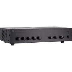
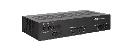
ES 2160
MIXER-AMPLIFIER WITH MP3 PLAYER AND BLUETOOTH
AMPLIFICATORE MIXER CON LETTORE MP3 E BLUETOOTH


3
CONTENTS
ENGLISH
CONTENTS ..................................................................................................................................................................................... 3
SAFETY PRECAUTIONS AND GENERAL INFORMATION .................................................................................................................... 4
DESCRIPTION ................................................................................................................................................................................. 6
FRONT PANEL ................................................................................................................................................................................ 7
REAR PANEL .................................................................................................................................................................................. 8
MP3 PLAYER ................................................................................................................................................................................ 11
AMPLIFIER OPERATION ................................................................................................................................................................ 14
SPEAKERS CONNECTION .............................................................................................................................................................. 16
POWER SUPPLY VOLTAGE CHANGE ............................................................................................................................................. 17
ITALIANO
AVVERTENZE PER LA SICUREZZA ................................................................................................................................................. 18
DESCRIZIONE ............................................................................................................................................................................... 21
PANNELLO FRONTALE .................................................................................................................................................................. 22
PANNELLO POSTERIORE ............................................................................................................................................................... 23
LETTORE MP3 .............................................................................................................................................................................. 26
FUNZIONAMENTO DELL'AMPLIFICATORE ..................................................................................................................................... 29
COLLEGAMENTO DEI DIFFUSORI ACUSTICI ................................................................................................................................... 31
CAMBIO TENSIONE DI FUNZIONAMENTO DELL'APPARECCHIO ..................................................................................................... 32
DIMENSIONS ................................................................................................................................................................................ 33
SPECIFICATIONS ........................................................................................................................................................................... 34
4
SAFETY PRECAUTIONS AND GENERAL INFORMATION
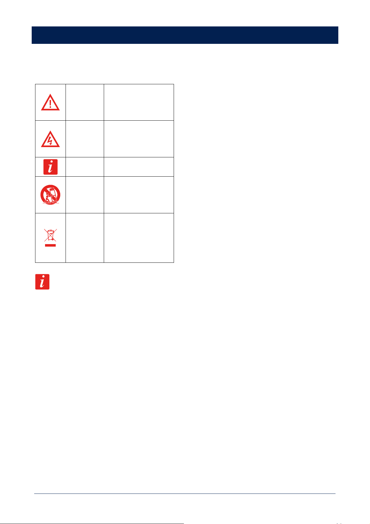
The symbols used in this document give notice of important
operating instructions and warnings which must be strictly
followed.
CAUTION
Important operating
instructions: explains hazards
that could damage a product,
including data loss.
WARNING
Important advice concerning the
use of dangerous voltages and
the potential risk of electric
shock, personal injury or death.
IMPORTANT
NOTES
Helpful and relevant
information about the topic.
SUPPORTS,
TROLLEYS
AND CARTS
Information about the use of
supports, trolleys and carts.
Reminds to move with extreme
caution and never tilt.
WASTE
DISPOSAL
This symbol indicates that this
product should not be disposed
with your household waste,
according to the WEEE directive
(2012/19/EU) and your national
law.
IMPORTANT NOTES
This manual contains important information about the correct
and safe use of the device. Before connecting and using this
product, please read this instruction manual carefully and
keep it on hand for future reference. The manual is to be
considered an integral part of this product and must
accompany it when it changes ownership as a reference for
correct installation and use as well as for the safety
precautions. RCF S.p.A. will not assume any responsibility for
the incorrect installation and / or use of this product.
SAFETY PRECAUTIONS
1. All the precautions, in particular the safety ones, must be
read with special attention, as they provide important
information.
2. Power supply from mains
a. The mains voltage is sufficiently high to involve a risk of
electrocution; install and connect this product before
plugging it in.
b. Before powering up, make sure that all the connections
have been made correctly and the voltage of your mains
corresponds to the voltage shown on the rating plate on
the unit, if not, please contact your RCF dealer.
c. The metallic parts of the unit are earthed through the
power cable. An apparatus with CLASS I construction shall
be connected to a mains socket outlet with a protective
earthing connection.
d. Protect the power cable from damage; make sure it is
positioned in a way that it cannot be stepped on or
crushed by objects.
e. To prevent the risk of electric shock, never open this
product: there are no parts inside that the user needs to
access.
f. Be careful: in the case of a product supplied by
manufacturer only with POWERCON connectors and
without a power cord, jointly to POWERCON connectors
type NAC3FCA (power-in) and NAC3FCB (power-out), the
following power cords compliant to national standard
shall be used:
- EU: cord type H05VV-F 3G 3x2.5 mm2 - Standard IEC
60227-1
- JP: cord type VCTF 3x2 mm2; 15Amp/120V~ -
Standard JIS C3306
- US: cord type SJT/SJTO 3x14 AWG; 15Amp/125V~ -
Standard ANSI/UL 62
3. Make sure that no objects or liquids can get into this
product, as this may cause a short circuit. This apparatus
shall not be exposed to dripping or splashing. No objects
filled with liquid, such as vases, shall be placed on this
apparatus. No naked sources (such as lighted candles)
should be placed on this apparatus.
4. Never attempt to carry out any operations, modifications
or repairs that are not expressly described in this manual.
Contact your authorized service centre or qualified
personnel should any of the following occur:
- The product does not function (or functions in an
anomalous way).
- The power cable has been damaged.
- Objects or liquids have got in the unit.
- The product has been subject to a heavy impact.
5. If this product is not used for a long period, disconnect the
power cable.
6. If this product begins emitting any strange odours or
smoke, switch it off immediately and disconnect the power
cable.
7. Do not connect this product to any equipment or
accessories not foreseen.
For suspended installation, only use the dedicated anchoring
points and do not try to hang this product by using elements
that are unsuitable or not specific for this purpose. Also check
the suitability of the support surface to which the product is
anchored (wall, ceiling, structure, etc.), and the components
used for attachment (screw anchors, screws, brackets not
supplied by RCF etc.), which must guarantee the security of
the system / installation over time, also considering, for
example, the mechanical vibrations normally generated by
transducers. To prevent the risk of falling equipment, do not
stack multiple units of this product unless this possibility is
specified in the user manual.
5
8. RCF S.p.A. strongly recommends this product is
only installed by professional qualified installers
(or specialised firms) who can ensure correct
installation and certify it according to the
regulations in force. The entire audio system must
comply with the current standards and regulations
regarding electrical systems.
9. Supports, trolleys and carts.
The equipment should be only used on supports,
trolleys and carts, where necessary, that are recommended
by the manufacturer. The equipment / support / trolley /
cart assembly must be moved with extreme caution.
Sudden stops, excessive pushing force and uneven floors
may cause the assembly to overturn. Never tilt the
assembly.
10. There are numerous mechanical and electrical factors to
be considered when installing a professional audio system
(in addition to those which are strictly acoustic, such as
sound pressure, angles of coverage, frequency response,
etc.).
11. Hearing loss. Exposure to high sound levels can cause
permanent hearing loss. The acoustic pressure level that
leads to hearing loss is different from person to person and
depends on the duration of exposure. To prevent
potentially dangerous exposure to high levels of acoustic
pressure, anyone who is exposed to these levels should
use adequate protection devices. When a transducer
capable of producing high sound levels is being used, it is
therefore necessary to wear ear plugs or protective
earphones. See the manual technical specifications to
know the maximum sound pressure level.
OPERATING PRECAUTIONS
- Place this product far from any heat sources and always
ensure an adequate air circulation around it.
- Do not overload this product for a long time.
- Never force the control elements (keys, knobs, etc.).
- Do not use solvents, alcohol, benzene or other volatile
substances for cleaning the external parts of this product.
IMPORTANT NOTES
To prevent the occurrence of noise on line signal cables, use
screened cables only and avoid putting them close to:
- Equipment that produces high-intensity
electromagnetic fields
- Power cables
- Loudspeaker lines
WARNING! CAUTION! To prevent
the risk of fire or electric shock, never expose this
product to rain or humidity.
WARNING! To prevent electric shock
hazard, do not connect to mains power supply
while grille is removed.
WARNING! to reduce the risk of electric
shock, do not disassemble this product unless you
are qualified. Refer servicing to qualified service
personnel.
CORRECT DISPOSAL OF THIS PRODUCT
This product should be handed over to an authorized
collection site for recycling waste electrical and electronic
equipment (EEE). Improper handling of this type of waste
could have a possible negative impact on the environment and
human health due to potentially hazardous substances that
are generally associated with EEE. At the same time, your
cooperation in the correct disposal of this product will
contribute to the effective usage of natural resources. For
more information about where you can drop off your waste
equipment for recycling, please contact your local city office,
waste authority or your household waste disposal service.
CARE AND MAINTENANCE
To ensure a long-life service, this product should be used
following these advices:
- If the product is intended to be set up outdoors, be sure it
is under cover and protected to rain and moisture.
- If the product needs to be used in a cold environment,
slowly warm up the voice coils by sending a low-level
signal for about 15 minutes before sending high-power
signals.
- Always use a dry cloth to clean the exterior surfaces of the
speaker and always do it when the power is turned off.
CAUTION: to avoid damaging the exterior
finishes do not use cleaning solvents or abrasives.
WARNING! CAUTION! For powered
speakers, do cleaning only when the power is
turned off.
6
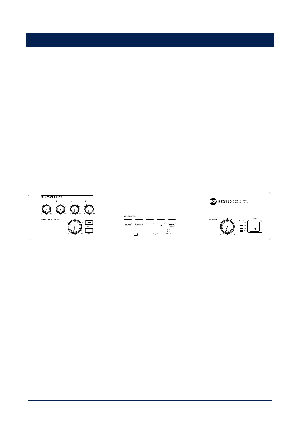
DESCRIPTION
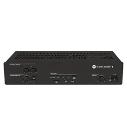
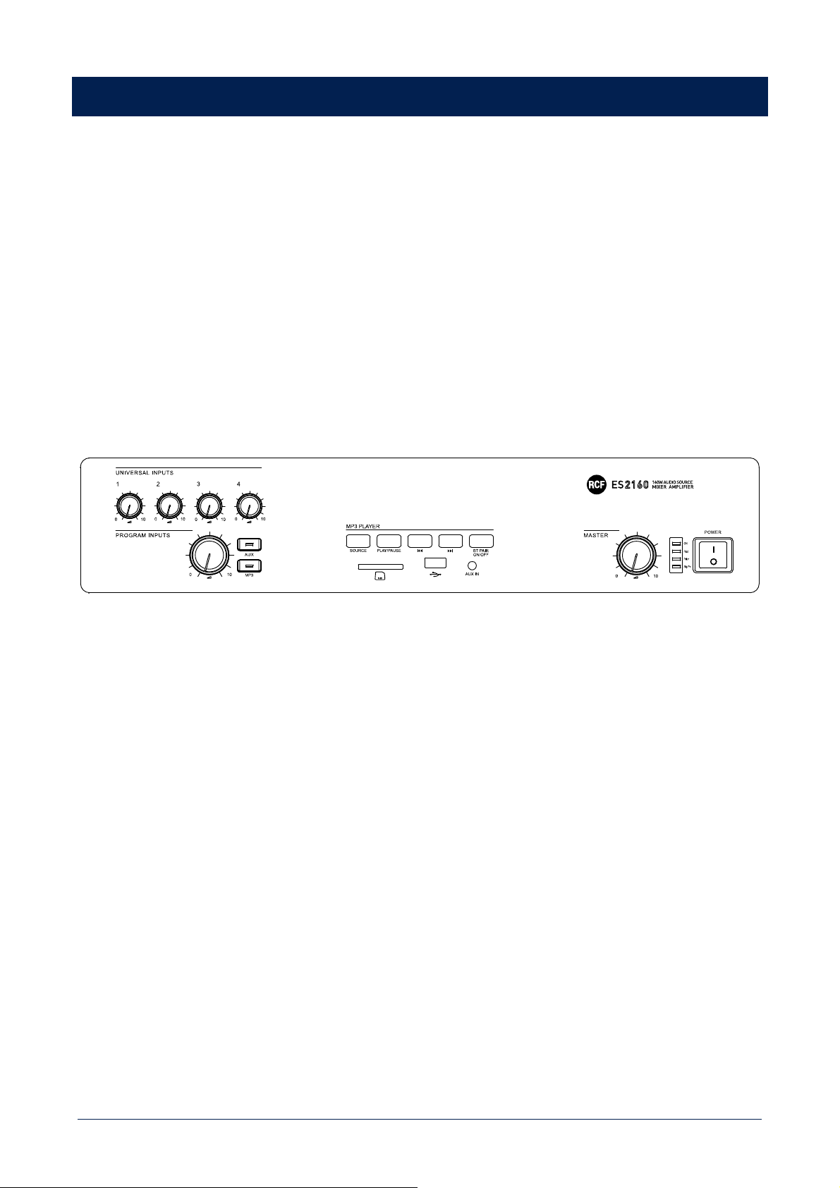
ES 2160 is a 160 W mixer-amplifier, with 4 mic-line audio inputs on removable connectors (the first input has also an XLR socket), an
MP3 player with Bluetooth and an aux input for a music source (i.e. CD players, tuners, etc.).
Input 1 has a signal detection circuit ('VOX') providing automatic priority operation.
All inputs 1, 2, 3 and 4 can access the priority through an external command (connected to the removable connector). Inputs 2 and 3
also have an RJ 45 socket for quick connection of a single RCF BM 3001 paging microphone (through CAT5 cable).
The amplifier output is available either for low impedance speakers (min. 4 Ω) or 100 – 70 V constant voltage line (for speakers
having 100 – 70 V transformers).
The MUSIC ON HOLD output directly sends the internal MP3 player signal to additional amplifiers, mixers, phone systems ('music on
hold' function), etc. .
The PRE OUT output sends the signal (the same mix routed to the internal amplifier) to additional amplifiers.
The 4 mic.-line inputs have a common PRESENCE control and separate high-pass filters that are useful for improving speech
intelligibility.
The internal MP3 player and the AUX INPUT have common tone controls.
Front panel LEDs indicate the device state (ON, PROT), priority circuit enabled (PRIOR) and the signal level / peak (SIG/PK).
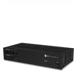
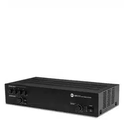
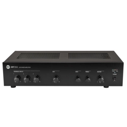
7
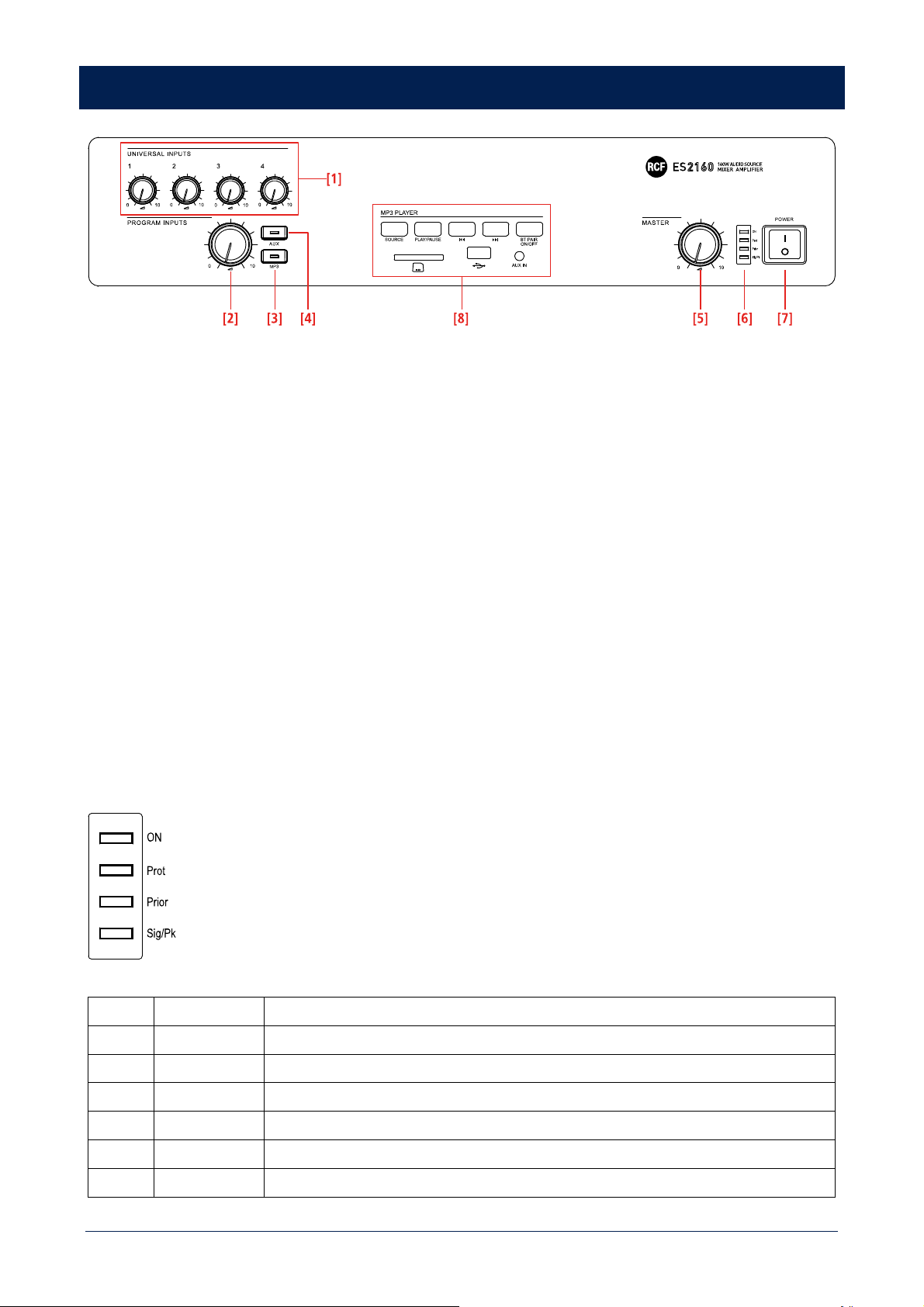
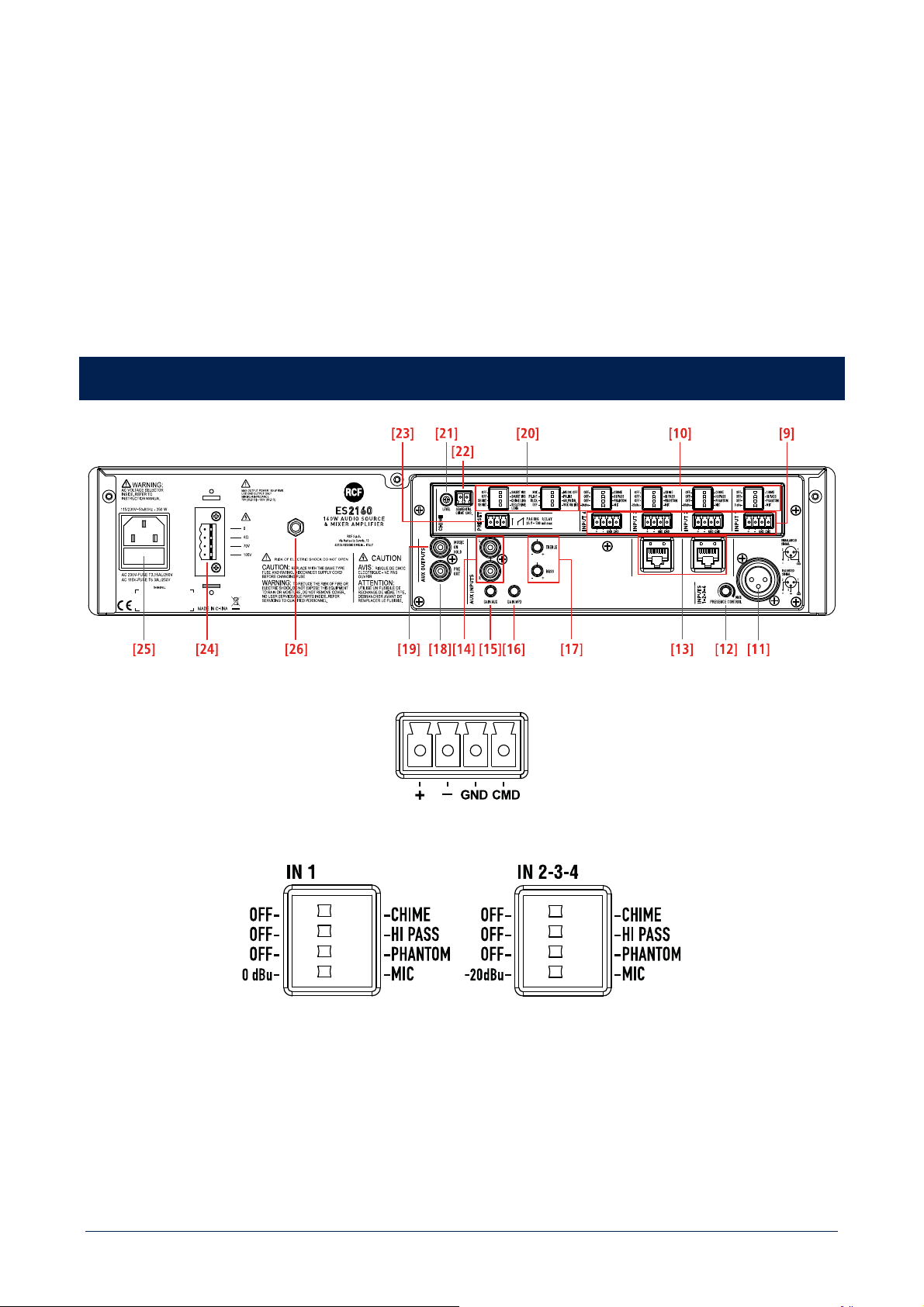
FRONT PANEL
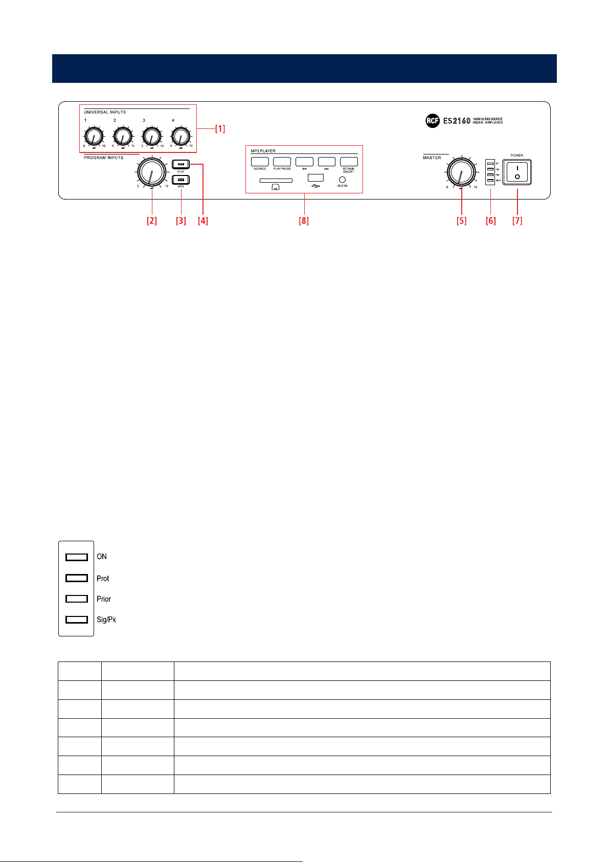
[1] Volume controls for each universal input (1, 2, 3, 4).
Note: unused input volume controls should always be turned fully counter clockwise (to 0).
[2] MP3 PLAYER [8] and AUX INPUT [14] volume control.
[3] AUX button (with LED). Press to turn on (the LED is lit) the AUX INPUT [14] (on the rear panel), which signal is sent to the
internal amplifier (and also PRE OUT [18]). If activated, the internal MP3 player will be muted (the MP3 button LED will turn off).
[4] MP3 button (with LED). Press to turn on (the LED is lit) the MP3 player, which signal is sent to the internal amplifier (and also
MUSIC ON HOLD [19] and PRE OUT [18] outputs). If activated, the AUX INPUT [14] on the rear panel will be muted (the AUX button
LED will turn off).
The MP3 player signal is always sent to the MUSIC ON HOLD [19] output (that is not affected by the volume control and MP3 / AUX
buttons).
[5] Internal amplifier MASTER volume control. Note: the audio outputs having RCA connectors (MUSIC ON HOLD [19] and PRE
OUT [18]) are not affected by the MASTER volume control.
[6] LEDs
ON
Green the device is switched on.
Prot
Red overload protection
Orange thermal protection
Prior
Yellow priority by either VOX function or an universal input or SEQ. CHIME CMD
Sig/Pk
Green the signal level is higher than - 15 dB
Green + Red the signal level is in the 0 ÷ +2 dB range
Red (peak) the signal level is equal or higher than +3 dB
8
0 dB = signal level that allows to get the amplifier maximum power.
The internal 'limiter' circuit helps to avoid the amplifier overloading, yet it is advisable to reduce the MASTER volume (or a single input
volume where a too high signal is present) when the SIG/PK LED is continuously indicating red.
[7] Main POWER switch (0 = off; I = on)
[8] MP3 PLAYER with Bluetooth (see the respective manual section).
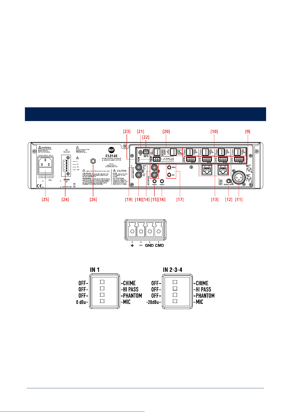
REAR PANEL
[9] Four balanced audio inputs (1, 2, 3, 4) with sockets for removable connectors.
[10] Each input has 4 dip-switches:
9
1
OFF – CHIME
OFF: the chime is disabled.
CHIME: the chime will be played as soon as a priority
command is activated.
2
OFF – HI PASS
OFF: the audio hi-pass filter is not inserted (flat
frequency response).
HI PASS: the audio hi-pass filter is inserted.
3
OFF – PHANTOM
OFF: the PHANTOM power supply is not
available on the respective audio input.
PHANTOM: the PHANTOM power supply is available
on the respective audio input.
4
IN 1
0 dBu – MIC
0 dBu: input level = 0 dBu (775 mV). MIC: microphone audio input.
IN 2, 3, 4
-20 dBu – MIC
-20 dBu: input level = -20 dBu (78 mV). MIC: microphone audio input.
Examples of dip-switches 3 and 4 settings:
DIP 3 DIP 4 MODE USE (EXAMPLES)
OFF 0 dBu 0 dBu (IN 1) CD/MP3 players, tuners, message players, phone systems
PHANTOM 0 dBu 0 dBu + PHANTOM (IN 1)
Pre-amplified (0 dBu output) paging microphone that needs
'phantom' power supply
OFF -20 dBu -20 dBu (IN 2, 3, 4) Audio source having a – 20 dBu output
PHANTOM -20 dBu -20 dBu + PHANTOM (IN 2, 3, 4) BM 3001 paging microphone
OFF MIC MIC Dynamic microphones
PHANTOM MIC MIC + PHANTOM Electret microphones
When a BM 3001 paging microphone is connected, it is necessary to choose the '-20 dBu + PHANTOM' mode in the respective input
(dip-switch no.3 set to PHANTOM; dip-switch no.4 set to -20 dBu).
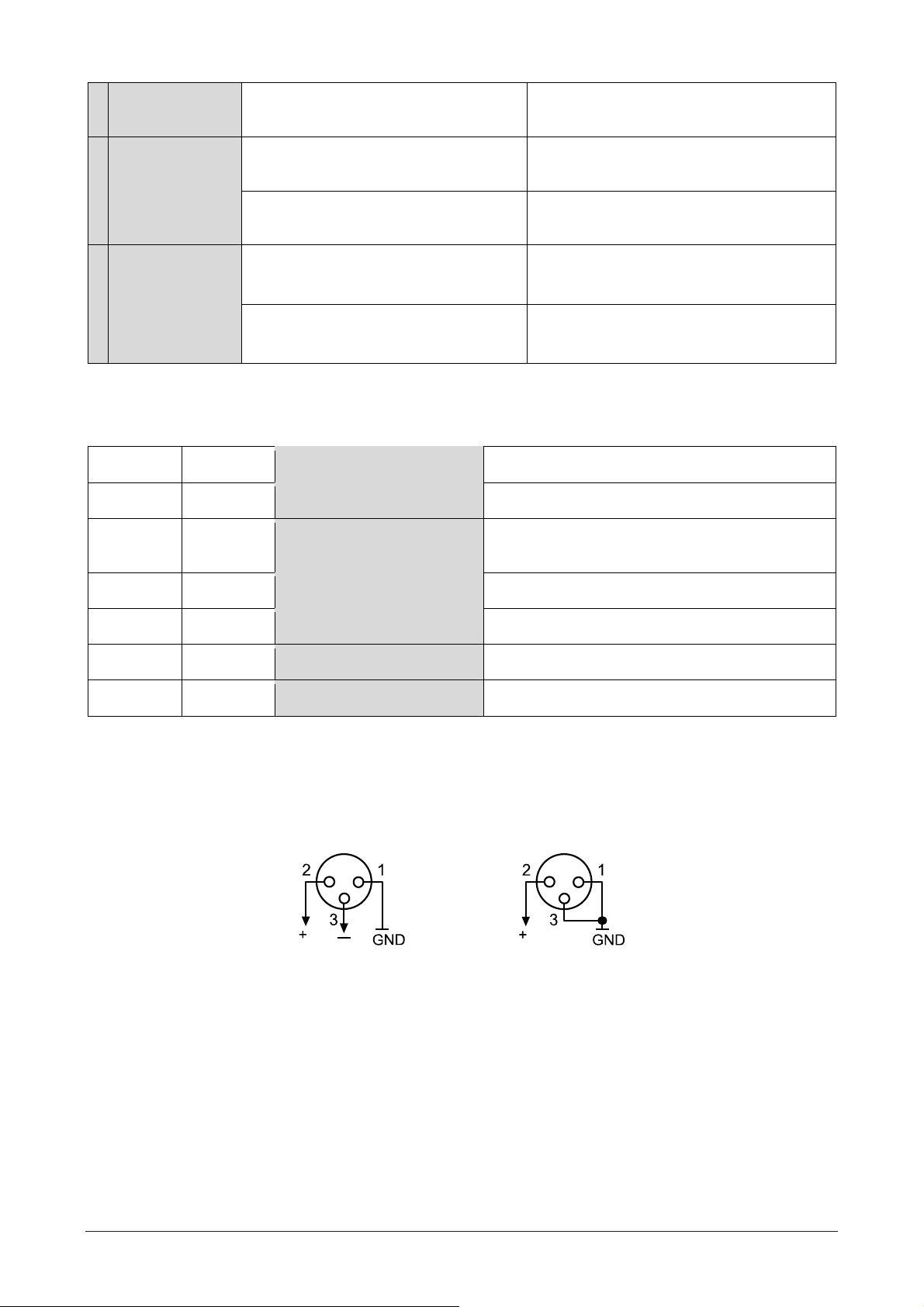
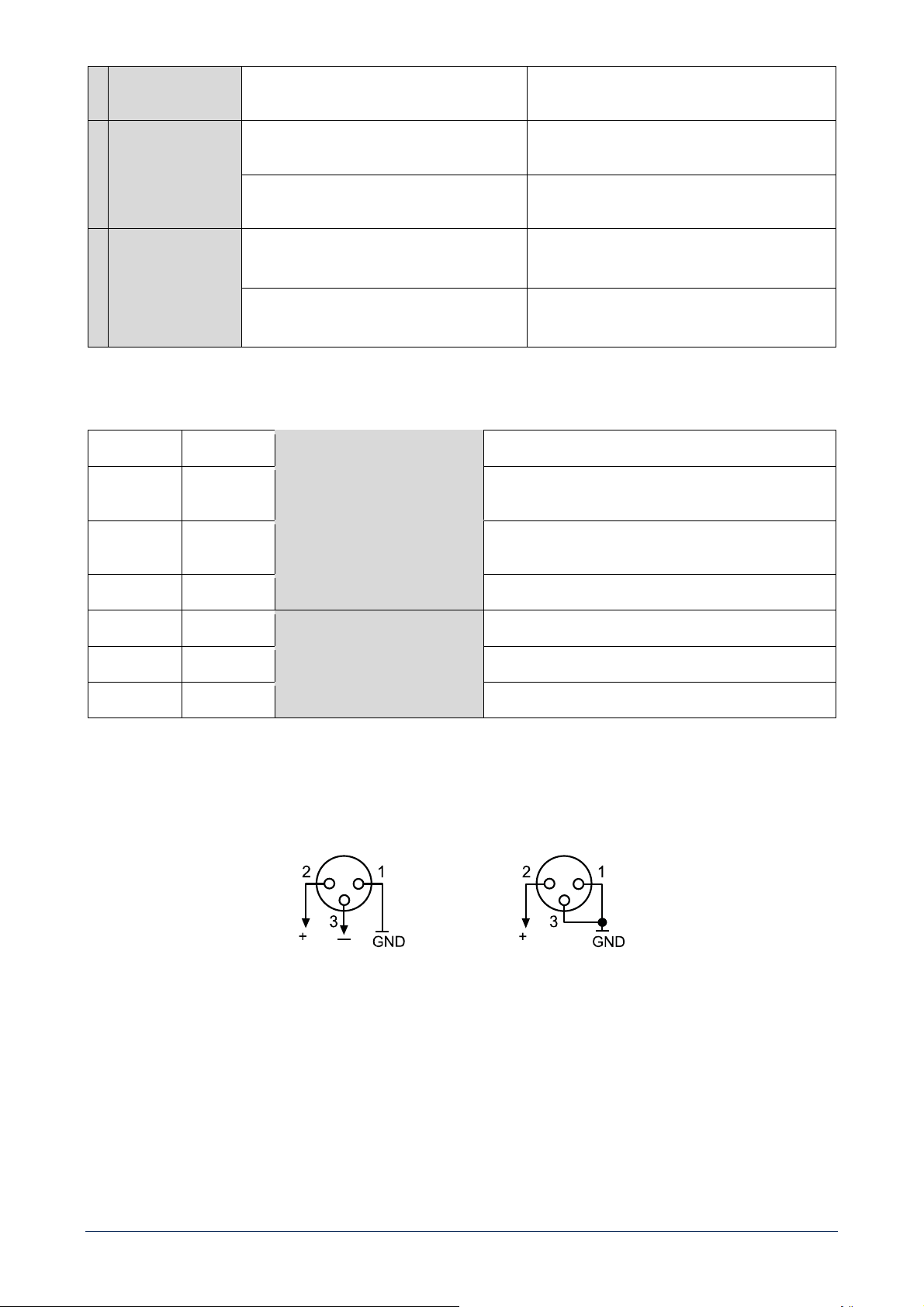
[11] Channel no.1 XLR input
Balanced connection Unbalanced connection
+ = hot – = cold GND = ground
Do NOT use an unbalanced connection when the 'Phantom' power supply is switched on.
[12] PRESENCE CONTROL (f = 2.15 kHz) common for all the inputs 1, 2, 3, 4.
[13] Two RJ 45 sockets (inputs 2 and 3) to connect a single RCF BM 3001 paging microphone.
Note: when a BM 3001 paging microphone is connected, it is necessary to set the dip-switches 3 and 4 of the respective input to the
-20 dBu + PHANTOM mode (see
[10]).

10
[14] AUX INPUT with dual RCA connector.
The two channels of the stereo source connected to the AUX INPUT are mixed internally (to get a mono signal).
[15] GAIN AUX: AUX INPUT gain control.
[16] GAIN MP3: MP3 player gain control.
[17] TREBLE and BASS controls for both the internal MP3 player and the AUX INPUT.
[18] PRE OUT audio output (with RCA connector) that sends the same signal routed to the internal amplifier (signal that can be
either a single source with priority or the mix of all the four inputs and either the internal MP3 player or the AUX INPUT).
Use PRE OUT to connect additional external amplifiers.
[19] MUSIC ON HOLD audio output (with RCA connector) that sends the internal MP3 audio signal (mono).
The MUSIC ON HOLD output is not affected by any volume control, nor a switch, and can be linked to a telephone system (in order to
get the 'Music On Hold' function).
[20] 8 dip-switches PRESET to set the priority options:
1
MIX – MUSIC OFF
MIX: the MP3 player or the AUX INPUT is always
present in the mix sent to the amplifier, even
during a priority command.
MUSIC OFF: the MP3 player or the AUX INPUT is
not sent to the amplifier during a priority
command.
2
PR. IN1 – PR. IN2
PR. IN1: the input 1 has the highest priority level
with override (but the SEQUENTIAL CHIME
CMD.) through the relevant command (or VOX),
if the dip-switch no.3 has been set to 'graduated
priority'.
PR. IN2: the input 2 has the highest priority level
with override (but the SEQUENTIAL CHIME
CMD.) through the relevant command, if the
dip-switch no.3 has been set to 'graduated
priority'.
3
I/LCK – GR. PRIOR.
I/LCK: interlocked priority mode (read the
'Amplifier operation' section).
GR. PRIOR.: graduated priority mode
(read the 'Amplifier operation' section).
4
OFF – VOX ON IN1
OFF: the channel 1 VOX function is off.
VOX ON IN1: the input 1 VOX function is turned
on (automatic priority when a signal is
detected).
5
OFF – SMART IN2
OFF: the input 2 priority is kept only if the
relevant command is still present
('push' mode).
SMART IN2: the input 2 priority is switched on /
off by every impulse of the relevant command
('toggle' mode).
6
OFF – SMART IN3
OFF: the input 3 priority is kept only if the
relevant command is still present
('push' mode).
SMART IN3: the input 3 priority is switched on /
off by every impulse of the relevant command
('toggle' mode).
7
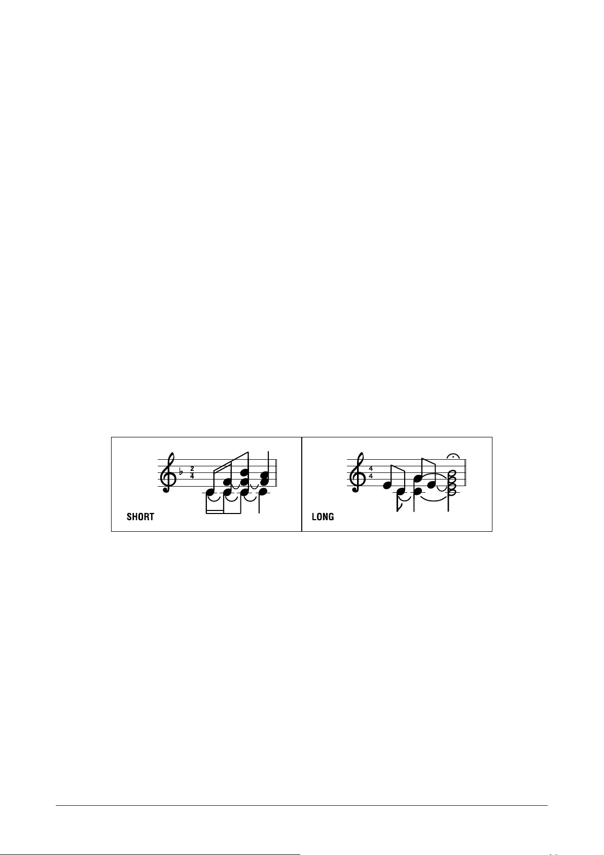
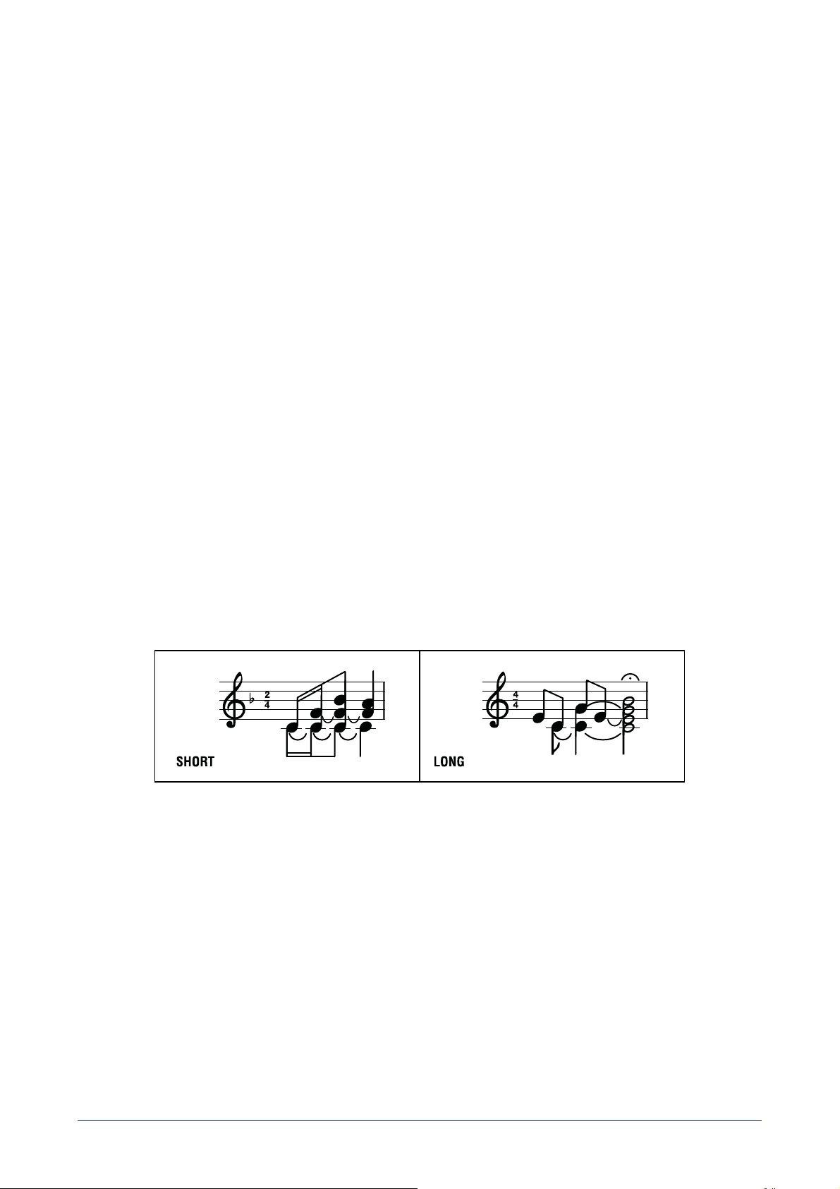
SHORT – CHIME LONG
SHORT: short chime (before paging). CHIME LONG: long chime (before paging).
8
SHORT – SEQ. CHIME
LONG
SHORT: the short chime is continuously played
when the SEQUENTIAL CHIME CMD. is
activated.
CHIME LONG: the long chime is continuously
played when the SEQUENTIAL CHIME CMD. is
activated.
[21] CHIME LEVEL (a trimmer adjustable by using a small screwdriver).
11
[22] SEQUENTIAL CHIME CMD. with removable connector (activated when the 2 pins are shorted) to play the chime continuously
(the chime type can be selected by setting the dip-switch no.8 PRESET, see [20]).
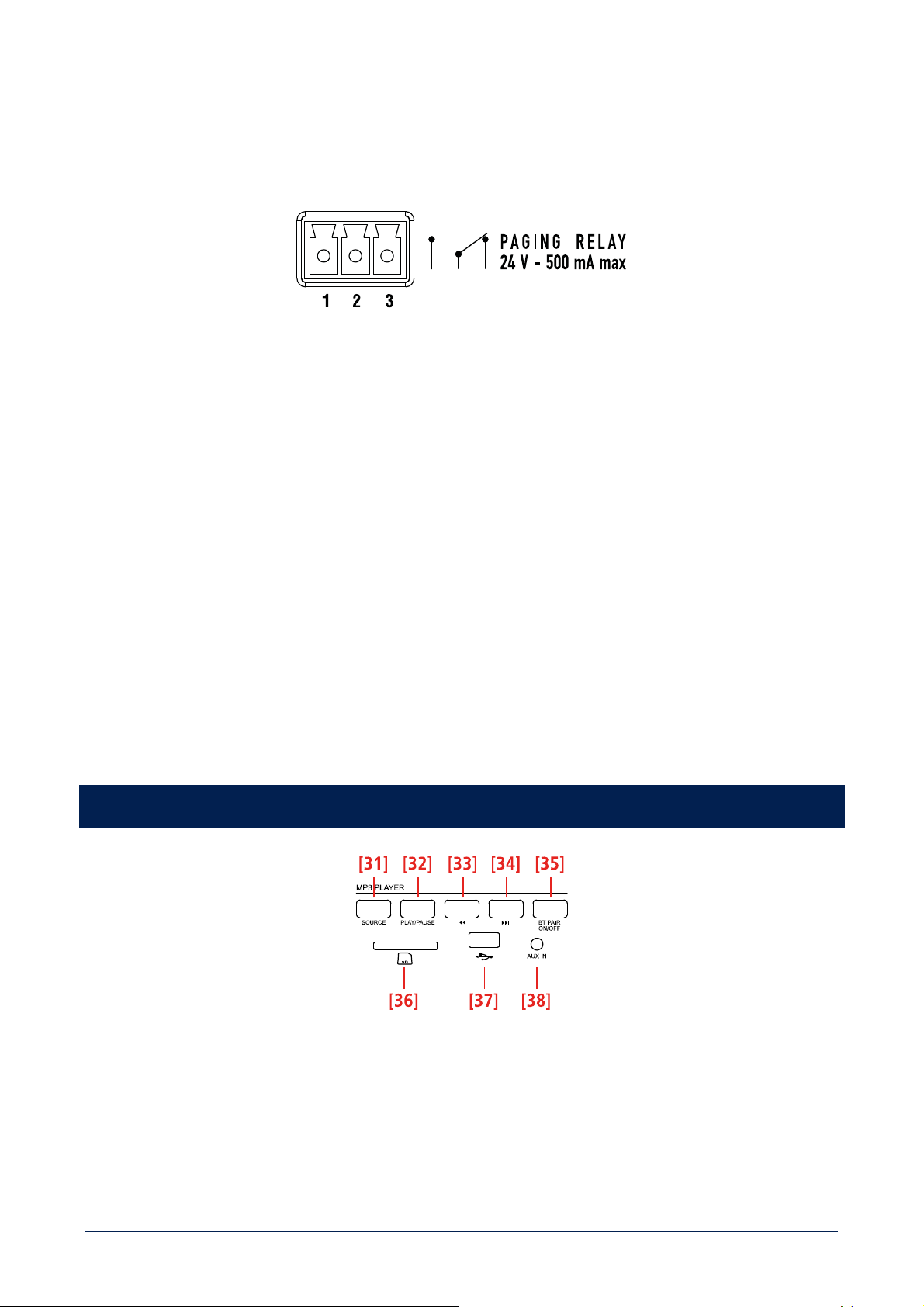
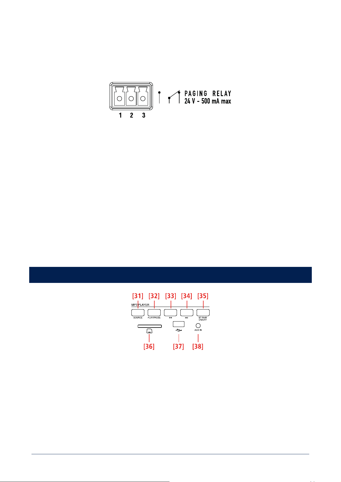
[23] PAGING RELAY contacts (3 pin removable connector).
The internal relays switches when a priority command is present.
1 = normally open 2 = common 3 = normally closed
Max. voltage on contacts: 24 V; max. current: 0.5 A
[24] Amplifier output (max. 160 W) to speakers, available as:
- 100 / 70 V constant voltage line
- Low impedance (min. 4 Ω).
Use 1 output only (see the section 'Speaker connection').
[25] Mains connector with fuse
Before connecting the power supply cable, verify that the apparatus voltage (230 or 115 V ac) corresponds to the available mains
supply.
Note: the fuse type is marked on the rear panel (below the mains connector).
[26] Antenna input (the antenna is necessary for Bluetooth).
MP3 PLAYER
[31] SOURCE button: push to loop among MP3 sources (BT, SD CARD, USB and AUX IN).
[32] PLAY/PAUSE button: push to start the playback (if stopped) or toggle play / pause the current MP3 file.
[33] ▐◄◄ button
While playing:
- If pushed once (only) for a while, the MP3 file begins again.

12
- Push twice or more times quickly to select previous MP3 files.
- Push and hold for fast backward of the current MP3 file.
[34] ►►▌ button
While playing:
- Push once or more times quickly to select next MP3 files.
- Push and hold for fast forward of the current MP3 file.
[35] BT PAIR ON/OFF button with bicolour LED
- Push once (for an instant) to make it detectable (for about a minute) to the external Bluetooth device.
- Push and hold (at least 3 seconds) to disable Bluetooth (the LED lights off); push and hold (at least 2 second) to enable Bluetooth
again).
LED INDICATION
OFF Bluetooth is disabled.
BLUE (2 seconds) / OFF (1 second) loop
Bluetooth is enabled, but the player is in stand-by, waiting for pairing to
the external device.
BLUE blinking every 2 seconds The player is connected to an external Bluetooth (A2DP) device.
BLUE steady lit
The player is connected to an external Bluetooth (A2DP) device and is
currently receiving streaming audio.
BLUE / RED
alternate and continuous flashing
The player is currently detectable (for about a minute) by the external
Bluetooth device.
[36] 'Secure Digital' SD CARD SDHC port (max. 32 GB).
Do NOT insert an SD CARD if a USB flash-drive is already inserted into its respective port [37].
[37] Port for a USB flash drive (max. 32 GB).
The insertion of a USB flash drive is automatically detected.
Do NOT insert a USB flash drive if an SD CARD is already inserted into its respective port [36].
Notes about USB flash drives:
- Format: FAT 12 / FAT 16 / FAT 32.
- File name: 32 byte / dir. name: 32 byte / tag name: 32 byte.
- USB 1.1 support and also 2.0 (but at the same speed of USB 1.1).
Some USB flash drive types may not be compatible.
[38] AUX IN (1/8” TRS jack): MP3 player aux input to connect (via cable) the audio output of an external device.
To enable this input, it is necessary to remove the USB flash drive / SD CARD (if inserted) and / or disconnect the external Bluetooth
device.
Note: do not confuse this input with the other AUX INPUT [14] on the rear panel.

13
INPUT / MEMORY AUTOMATIC SELECTION
The MP3 player automatically selects inputs / memories with different priority levels as follows:
1. (highest priority) Bluetooth external device, if connected and sending streaming audio.
2. When Bluetooth external device is playing and then disconnected, audio source won’t do any switch automatically, and it will
be needed to select the MP3 source with SOURCE button.
3. When a MP3 source is playing and a Bluetooth device is connected, music will be switched to BT.
NOTES ABOUT MP3 FILES
- MP3: means MPEG Audio Layer 3 and refers to an audio compression type.
- This player reads MP3 files on USB flash drives and SD cards.
- The file extension must be .mp3.
- The max. directory (/ folder) level is 8, including the 'root'.
- It is advisable to use MP3 files having a sampling frequency of 44.1 kHz and a fixed bit-rate of at least 128 kbps (if higher, for
instance 192 kbps, the sound quality will be better).
- The player may not play MP3 files in the order as written on the USB flash drive / SD CARD.
BLUETOOTH DEVICES
'Bluetooth' is a wireless technology standard for exchanging data over short distances from fixed and mobile devices (e.g. cellular
phones).
The MP3 player includes a Bluetooth interface to receive audio signals from compatible external devices, which must have A2DP
technology ('Advanced Audio Distribution Profile').
To connect your Bluetooth external device to the MP3 player:
1. Check if the antenna [26] on the rear panel is properly connected and oriented.
2. Enable 'Bluetooth' on the external device.
3. Push the MP3 player BT PAIR ON/OFF button [35] (its LED now flashes blue / red).
4. Within a minute, on the external device, start searching other devices with active Bluetooth; ES2160 should be displayed.
5. Pair the external device and ES 2160.
6. Start the audio playback on the external device (which should be now included in the available sources of the internal MP3
player).
When turning ES 2160 on, the MP3 player automatically tries to connect (via 'Bluetooth') to the last paired external device (if available).

14
AMPLIFIER OPERATION
'VOX' is an internal circuit that automatically activates the input 1 priority when a signal is detected on its sockets.
Power on (or when a priority command ends)
If no priority command is present (including VOX and SEQUENTIAL CHIME COMMAND), all the inputs 1, 2, 3, 4 and the MP3 PLAYER
(or the AUX INPUT) are mixed together.
The music volume (either the MP3 PLAYER or the AUX INPUT source) depends on the front panel volume control [2] and also the
respective GAIN control settings (
[15] or [16]) on the rear panel.
Priority
If a priority command is present (or VOX), the MP3 PLAYER (or the AUX INPUT) can be either included in the mix sent to the amplifier
or muted, according to dip-switch no.1 setting (see [20]: the eight dip-switch group).
During a priority command ('PRIOR' LED turns on), only the audio signal of the channel with priority (and the MP3 PLAYER / AUX
INPUT, if enabled) is sent to the amplifier (and the PRE OUT output).
The MP3 PLAYER (or the AUX INPUT) is always muted in the mix sent to the amplifier when the CHIME SEQUENTIAL COMMAND is
activated.
The priority mode and the VOX function are set through the dip-switches no.2 and no.3 of the eight dip-switch group (see [20]):
DIP 2 DIP 3 MODE
---- I/LCK INTERLOCKED
Only the first priority command of inputs 1 to 4 (and also
channel 1 VOX, if enabled through the dip-switch no.4) is
accepted.
Any other later priority command will not be accepted until
the previous is removed.
Note: the only event that can always be activated later (and
can override a previous priority) is the SEQUENTIAL CHIME
CMD. .
PRIO IN1 GR. PRIOR.
GRADUATED PRIORITY
1
A priority command having a higher level can override the
previous one. The priority levels are:
1. (highest) SEQUENTIAL CHIME CMD.
2. input 1 (including VOX)
3. input 2
4. input 3
5. input 4
PRIO IN2 GR. PRIOR.
GRADUATED PRIORITY
2
A priority command having a higher level can override the
previous one. The priority levels are:
1. (highest) SEQUENTIAL CHIME CMD.
2. input 2
3. input 1 (including VOX)
4. input 3
5. input 4
The dip-switch no.2 (8 dip-switch group) allows you to switch the priority level between the inputs 1 and 2.
This setting does not work in the interlocked priority mode.
15
As soon as a priority event ends, the initial state will be restored (all the inputs 1, 2, 3, 4, the MP3 PLAYER or the AUX INPUT will be
mixed together, unless another priority event is in progress).
Sequential Chime Cmd.
The SEQUENTIAL CHIME COMMAND makes the chime (either short or long, depending on the dip-switch no.8 setting, see [20]) be
continuously played. This command has the highest priority level and always mutes the MP3 player (or the aux input) in the mix sent
to the amplifier.
Channel 2 - 3 'push' / 'toggle' priority mode
The dip-switches no.5 and no.6 (eight dip-switch group, see [20]) allow the choice of the priority mode for inputs 2 and 3 between
'push' (the priority is kept only if the command is still present) and 'toggle' (the priority is switched on / off by every impulse of the
command).
Note: the chosen priority mode is applied to both BM 3001 paging microphones (if present) and priority commands (of removable
connectors).
4 dip-switch group (one per each input 1 to 4)
Each input gain can be set to either MIC or -20 dBu (0 dBu for the input 1).
It is also possible to turn the PHANTOM power supply on/off, to insert or remove the high-pass filter and to enable or disable the
chime, which is played on every priority event.
Information about the CHIME
The chime is not played when using the channel 1 VOX function (a priority command is needed to play the chime).
Its melody can be either short or long (dip-switch no.7 of the eight dip-switch group, see [20]).
During the chime playback (a few seconds), the MP3 player (or the AUX INPUT) is not sent to the amplifier.
RCF BM 3001 paging microphone (not included)
Both inputs 2 and 3 have an RJ 45 socket, to which a single BM 3001 paging microphone can be connected (note: it is necessary to
set the dip-switches no.3 and no.4 to the '-20 dBu + PHANTOM' mode, see [10], the second table).
When the BM 3001 paging microphone is on (ready to talk), its LED turns ON.
During the chime playback (if the chime is enabled), the BM 3001 microphone is momentarily muted.
The paging microphone priority mode depends on the settings mentioned above.
The paging microphone is muted by events having a higher priority level (than the input 2 or 3, to which the paging microphone is
connected).
16
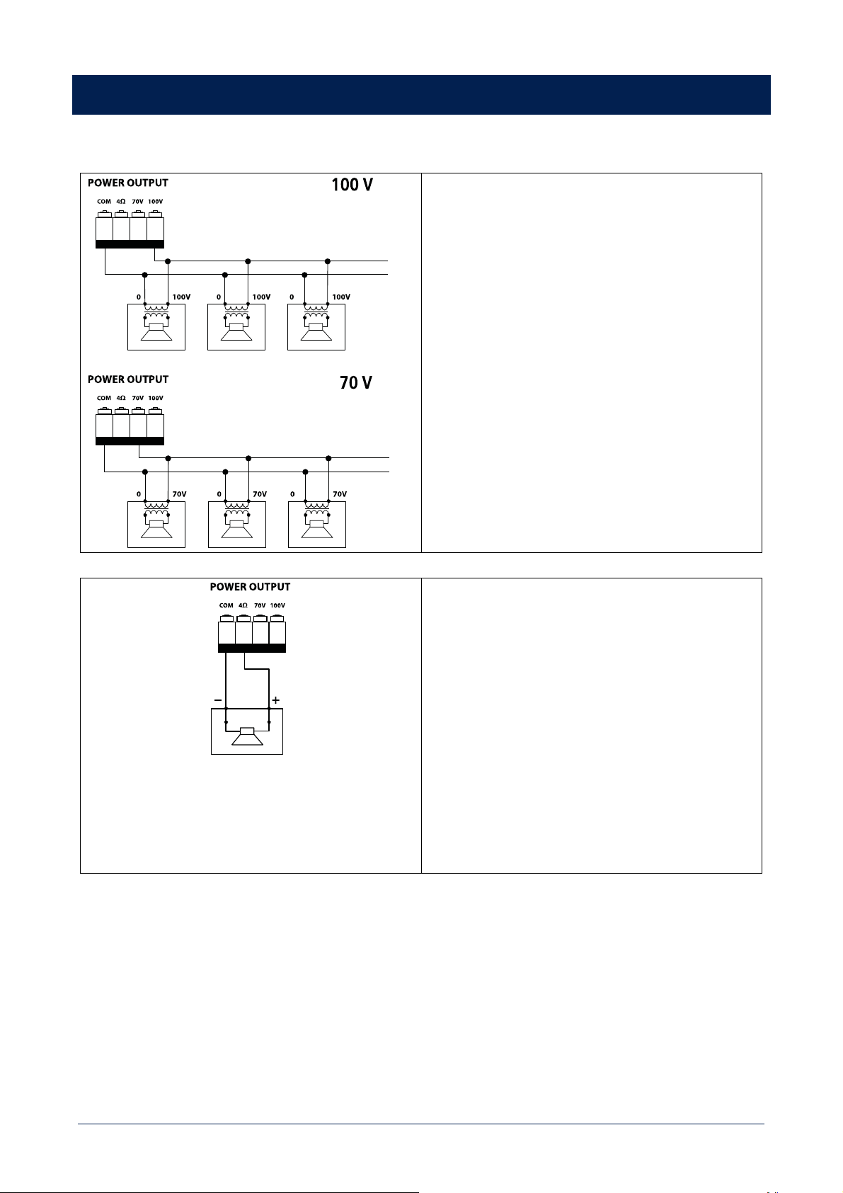
SPEAKERS CONNECTION
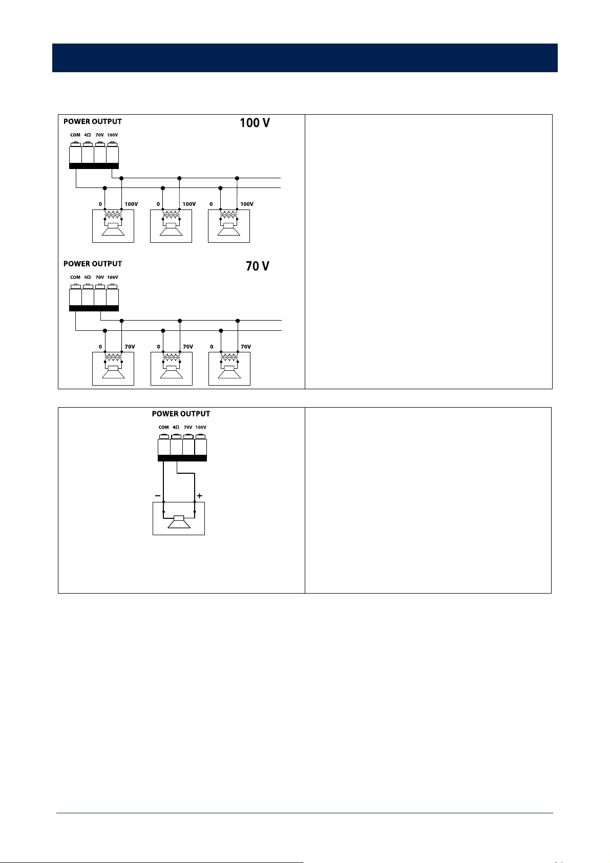
Use 1 output only, DO NOT MIX 100 / 70 V and 4 Ω CONNECTIONS!
100 / 70 V CONSTANT VOLTAGE OUTPUTS
- Each speaker shall have a line transformer with the input
voltage equal to the line voltage (100 / 70 V).
- The speaker total power shall not be higher than the
amplifier maximum power (160 W).
LOW IMPEDANCE OUTPUT (4 Ω)
- The speaker total impedance shall not be lower than 4 Ω.
Note: a total impedance equal to 4 Ω allows the amplifier
maximum power delivery. A higher impedance leads to a
reduction of the power delivered by the amplifier (e.g. 8 Ω:
approx. ½ power, 16 Ω: approx. ¼ power). An impedance
lower than 4 Ω overloads the amplifier.
- Speaker models shall be chosen by considering the
maximum power (160 W) that the amplifier can deliver.
- Speaker line should be as short as possible, as long cables
may need large wire cross-sections.
- Do not use, at the same time, both the low impedance
output (4 Ω) and the constant voltage output (100V or
70V), as this overloads the amplifier.
17
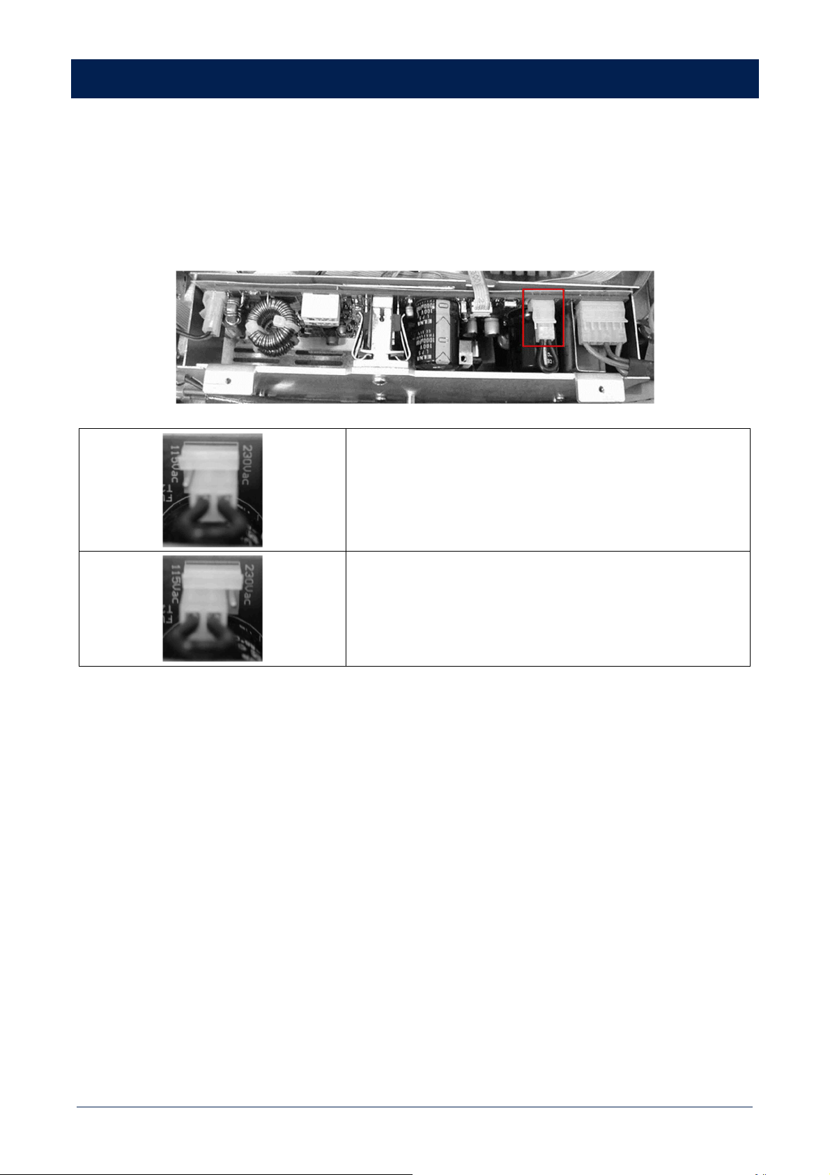
POWER SUPPLY VOLTAGE CHANGE
IMPORTANT: This manual section concerns qualified personnel only. The following instructions are to be ignored by
the user.
- Make sure the amplifier is not connected to the mains (unplug the power cord).
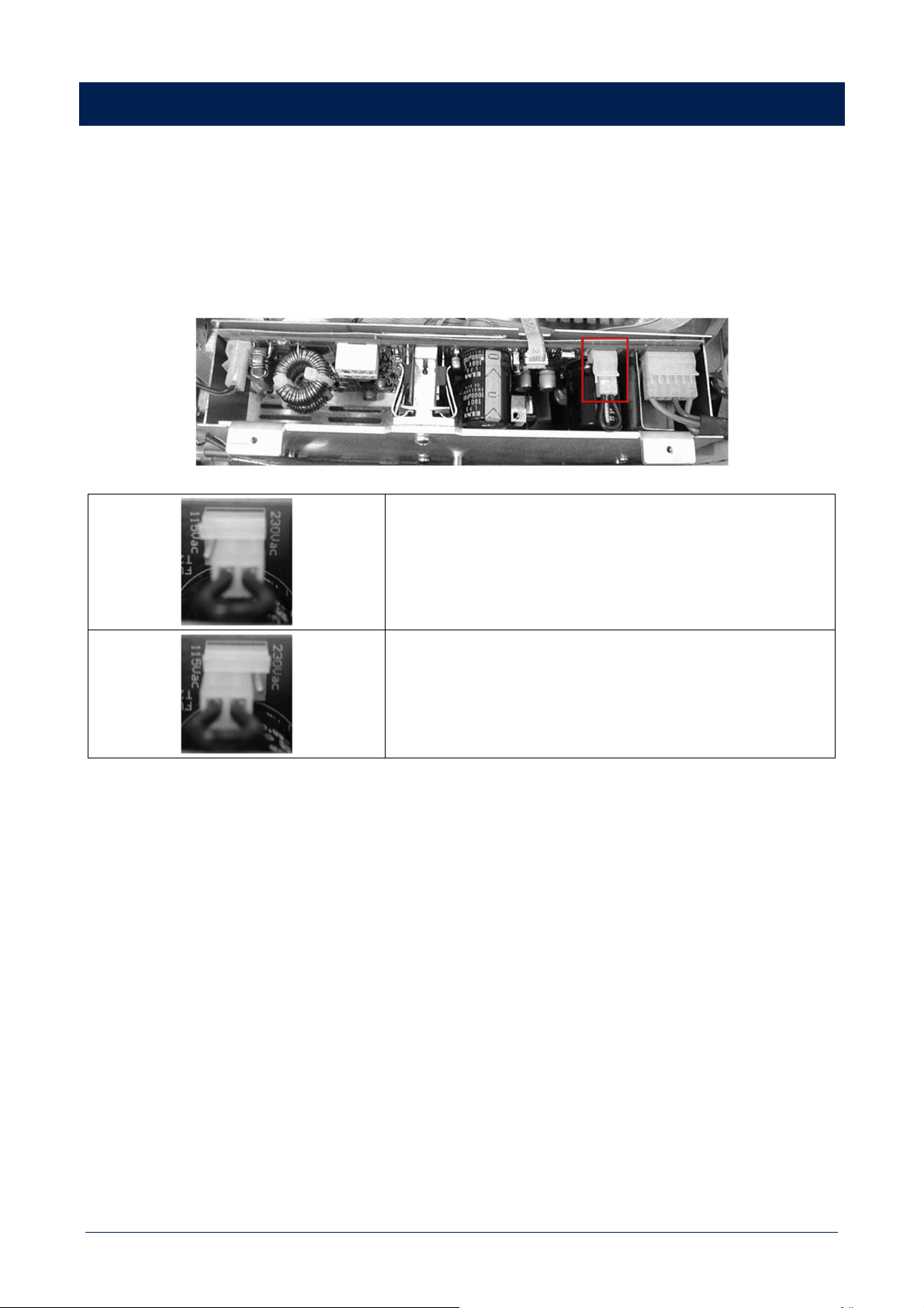
- Remove the lid.
The voltage change connector is highlighted by a square.
If the mains voltage is 230 V, set the connector to the 230Vac position,
according to the PCB indication (looking at the connector front, the central
pin is connected to the right one).
If the mains voltage is 115 V, set the connector to the 115 Vac position,
according to the PCB indication (looking at the connector front, the central
pin is connected to the left one).
Refit the amplifier lid.
Before connecting the amplifier to the mains, make sure that the fuse (inside the IEC power supply connector of the rear panel, see
[25]) is the correct current rating for the mains voltages (read the fuse indication below the connector).
18
AVVERTENZE PER LA SICUREZZA
I simboli utilizzati in questo documento notificano importanti
istruzioni operative e avvertimenti che devono essere seguiti
attentamente.
CAUTELA
Importante istruzione operativa:
notifica un pericolo che
potrebbe danneggiare il
prodotto, compresa la perdita di
dati.
ATTENZIONE
Avvertimento importante
riguardante l’uso di voltaggi
pericolosi e il potenziale rischio
di shock elettrico, lesioni
personali o morte.
NOTE
IMPORTANTI
Informazioni utili e rilevanti
sull’argomento.
SUPPORTI,
TROLLEY E
CARRRELLI
Informazioni riguardanti
l’utilizzo di supporti, trolley e
carrelli. Suggerisce di muovere
con estrema cautela e di non
inclinare il carico.
SMALTIMENTO
Questo simbolo indica che il
prodotto non deve essere
smaltito con i rifiuti ordinari,
così come indicato nella
direttiva WEEE (2012/19/ EU) e
nelle normative nazionali in
vigore.
NOTE IMPORTANTI
Questo manuale contiene informazioni importanti sull’uso
corretto e sicuro del dispositivo. Prima di collegare e utilizzare
questo prodotto, leggere attentamente questo manuale di
istruzioni e tenerlo a portata di mano per riferimenti futuri. Il
manuale deve essere considerato parte integrante di questo
prodotto e deve accompagnarlo in caso di cambio proprietà
come riferimento per la corretta installazione e utilizzo nonché
per le precauzioni di sicurezza. RCF S.p.A. non si assume
alcuna responsabilità per l’installazione e / o l’uso errati di
questo prodotto.
PRECAUZIONI DI SICUREZZA
1. Tutte le precauzioni, in particolare quelle di sicurezza,
devono essere lette con particolare attenzione, in quanto
forniscono informazioni importanti.
2. Alimentazione principale da rete elettrica
a. La tensione di rete è sufficientemente elevata da
comportare un rischio di folgorazione; installare e
collegare questo prodotto prima di collegarlo.
b. b. Prima di accendere, assicurarsi che tutti i
collegamenti siano stati eseguiti correttamente e che la
tensione della rete corrisponda alla tensione indicata
sulla targhetta dei dati sull’unità, in caso contrario,
contattare il rivenditore RCF.
c. Le parti metalliche dell’unità sono messe a terra
attraverso il cavo di alimentazione. Un apparecchio con
costruzione di CLASSE I deve essere collegato a una
presa di corrente con un collegamento di terra di
protezione.
d. Proteggere il cavo di alimentazione da danni; assicurarsi
che sia posizionato in modo tale da non poter essere
calpestato o schiacciato da oggetti.
e. Per evitare il rischio di scosse elettriche, non aprire mai
questo prodotto: non sono previste parti interne alle
quali l’utente debba accedere.
f. Fare attenzione: nel caso di un prodotto provvisto solo
di connettori POWERCON e senza cavo di alimentazione,
congiuntamente ai connettori POWERCON tipo
NAC3FCA (alimentazione) e NAC3FCB (alimentazione),
devono essere usati i seguenti cavi di alimentazione
conformi alla norma nazionale:
- EU: cavo di tipo H05VV-F 3G 3x2.5 mm2 -
Standard IEC 60227-1
- JP: cavo di tipo VCTF 3x2 mm2; 15Amp/120V~ -
Standard JIS C3306
- US: cavo di tipo SJT/SJTO 3x14 AWG;
15Amp/125V~ - Standard ANSI/UL 62
3. Assicurarsi che nessun oggetto o liquido penetri in
questo prodotto poiché ciò potrebbe causare un corto
circuito. Questo apparecchio non deve essere esposto a
gocciolamenti o spruzzi. Nessun oggetto riempito di
liquido, come vasi, deve essere posizionato su questo
apparecchio. Nessuna fiamma libera (come candele
accese) deve essere posizionata su questo apparecchio.
4. Non tentare mai di eseguire operazioni, modifiche o
riparazioni non espressamente descritte nel presente
manuale. Contattare il centro di assistenza autorizzato o
personale qualificato qualora si verifichi una delle
seguenti condizioni:
- Il prodotto non funziona (o funziona in
modo anomalo).
- Il cavo di alimentazione è stato
danneggiato.
- Oggetti o liquidi sono entrati nell’unità.
- Il prodotto ha subìto un forte urto.
5. Se questo prodotto non viene utilizzato per un lungo
periodo, scollegare il cavo di alimentazione.
6. Se questo prodotto inizia a emettere strani odori o fumo,
spegnerlo immediatamente e scollegare il cavo di
alimentazione.
7. Non collegare questo prodotto ad apparecchiature o
accessori non previsti. Per l’installazione sospesa,
utilizzare solo i punti di ancoraggio dedicati e non
tentare di appendere questo prodotto utilizzando
elementi non idonei o non specifici per questo scopo.
Verificare inoltre l’idoneità della superficie di supporto a
19
cui è ancorato il prodotto (parete, soffitto, struttura, ecc.)
a dei componenti utilizzati per il fissaggio (tasselli, viti,
staffe non fornite da RCF ecc.) che devono garantire
sicurezza del sistema / installazione nel tempo, anche
considerando, ad esempio, le vibrazioni meccaniche
normalmente generate dai trasduttori. Per evitare il
rischio di caduta dell’apparecchiatura, non impilare più
unità di questo prodotto a meno che questa possibilità
non sia specificata nel manuale dell’utente.
8. RCF S.p.A. raccomanda vivamente che questo prodotto
sia installato solo da installatori professionisti qualificati
(o aziende specializzate) che possono garantire la
corretta installazione e certificarlo secondo le normative
vigenti. L’intero sistema audio deve essere conforme agli
standard e alle normative vigenti in materia di sistemi
elettrici.
9. Supporti, trolley e carrelli.
L’apparecchiatura deve essere utilizzata, ove
necessario, solo su supporti, trolley e carrelli consigliati
dal produttore. L’apparecchiatura / supporto / carrello
deve essere spostata con estrema cautela. Arresti
improvvisi, eccessiva spinta e pavimenti irregolari
possono causarne il ribaltamento. Non inclinare mai.
10. Vi sono numerosi fattori meccanici ed elettrici da
considerare quando si installa un sistema audio
professionale (oltre a quelli strettamente acustici, come
la pressione del suono, gli angoli di copertura, la risposta
in frequenza, ecc.).
11. Perdita dell’udito. L’esposizione a livelli sonori elevati
può causare la perdita permanente dell’udito. Il livello di
pressione acustica che porta alla perdita dell’udito è
diverso da persona a persona e dipende dalla durata
dell’esposizione. Per prevenire un’esposizione
potenzialmente pericolosa a livelli elevati di pressione
acustica, chiunque sia esposto a questi livelli dovrebbe
usare adeguati dispositivi di protezione. Quando viene
utilizzato un trasduttore in grado di produrre alti livelli
sonori, è quindi necessario indossare tappi per le
orecchie o cuffie protettive. Vedere le specifiche tecniche
del manuale per conoscere il livello massimo di pressione
sonora.
PRECAUZIONI OPERATIVE
- Posizionare questo prodotto lontano da qualsiasi fonte
di calore e garantire sempre un’adeguata circolazione
dell’aria attorno ad esso.
- Non sovraccaricare questo prodotto per molto tempo.
- Non forzare mai gli elementi di controllo (tasti,
manopole, ecc.).
- Non utilizzare solventi, alcool, benzene o altre sostanze
volatili per pulire le parti esterne di questo prodotto.
NOTE IMPORTANTI
Per evitare il verificarsi di disturbi sui cavi di segnale in linea,
utilizzare solo cavi schermati ed evitare di avvicinarli a:
- Apparecchiature che producono campi
elettromagnetici ad alta intensità
- Cavi di alimentazione
- Linee di altoparlanti
ATTENZIONE! CAUTELA! Per
evitare il rischio di incendi o scosse elettriche, non
esporre mai questo prodotto a pioggia o umidità.
ATTENZIONE! Per evitare il rischio di
scosse elettriche, non collegare all’alimentazione
di rete mentre la griglia è rimossa.
WARNING! Per ridurre il rischio di scosse
elettriche, non smontare questo prodotto se non si
è qualificati. Per l’assistenza rivolgersi a personale
di assistenza qualificato.
SMALTIMENTO CORRETTO DEL PRODOTTO
Questo prodotto deve essere consegnato a un sito di raccolta
autorizzato per il riciclaggio di apparecchiature elettriche ed
elettroniche (AEE). Una manipolazione impropria di questo
tipo di rifiuti potrebbe avere un possibile impatto negativo
sull’ambiente e sulla salute umana a causa di sostanze
potenzialmente pericolose che sono generalmente associati
alle AEE. Allo stesso tempo, la vostra collaborazione per il
corretto smaltimento di questo prodotto contribuirà all’utilizzo
efficace delle risorse naturali. Per ulteriori informazioni su dove
sia possibile scaricare le attrezzature per il riciclaggio, si prega
di contattare l’ufficio comunale locale, l’autorità competente
per i rifiuti o il servizio di smaltimento dei rifiuti domestici.
CURA E MANUTENZIONE
Per garantire un servizio di lunga durata, questo prodotto deve
essere utilizzato seguendo questi consigli:
- Se il prodotto deve essere installato all’aperto,
assicurarsi che sia coperto e protetto da pioggia e
umidità.
- Se il prodotto deve essere utilizzato in un ambiente
freddo, riscaldare lentamente le bobine vocali inviando
un segnale di basso livello per circa 15 minuti prima di
inviare segnali ad alta potenza.

20
- Utilizzare sempre un panno asciutto per pulire le
superfici esterne dell’altoparlante e farlo sempre quando
l’alimentazione è spenta
CAUTELA! Per evitare di danneggiare le
finiture esterne non utilizzare solventi per la pulizia
o abrasivi.
ATTENZIONE! CAUTELA! Per gli
altoparlanti alimentati, eseguire la pulizia solo
quando l’alimentazione è spenta.
21
DESCRIZIONE
ES 2160 è un mixer-amplificatore con potenza 160 W, avente 4 ingressi audio universali (mic.-linea) su connettori rimovibili (l'ingresso
1 dispone inoltre di un connettore XLR), un lettore di file MP3 con interfaccia “Bluetooth” ed un ingresso ausiliario per un'eventuale
sorgente sonora esterna (es. lettore CD, sintonizzatore radio, ecc.).
Un circuito di rilevazione del segnale (“VOX”) con funzione di attivazione della priorità è presente sull'ingresso 1.
Tutti gli ingressi 1, 2, 3 e 4 possono ottenere la priorità tramite un comando esterno (collegato al connettore rimovibile); gli ingressi
2 e 3 hanno inoltre un connettore RJ 45 per la rapida connessione di una base microfonica dedicata BM 3001 (utilizzando del cavo
CAT5).
L'uscita per i diffusori acustici è disponibile sia a bassa impedenza (min. 4 Ω) oppure a tensione costante 100 – 70 V (per diffusori
con trasformatore).
Sono presenti:
- un'uscita audio MUSIC ON HOLD per inviare il segnale del lettore MP3 interno ad amplificatori addizionali oppure ad una centrale
telefonica (come musica d'attesa);
- un'uscita audio PRE OUT (riportante il segnale inviato all'amplificatore interno) per il collegamento di amplificatori esterni
addizionali.
I quattro ingressi universali hanno un controllo comune di “presenza” e filtri passa-alto (inseribili separatamente) utili per migliorare
l'intelligibilità della voce; l'ingresso ausiliario AUX INPUT ed il lettore MP3 hanno in comune i controlli di tono BASS e TREBLE.
Sono presenti indicatori luminosi relativi allo stato dell'apparecchio (ON, PROT), all'abilitazione del circuito di priorità (PRIOR) ed al
livello del segnale audio (SIG/PK).
22
PANNELLO FRONTALE
[1] Controlli del volume di ciascun ingresso universale 1, 2, 3, 4
Nota: nel caso uno o più ingressi non siano utilizzati, lasciare i relativi controlli a 0.
[2] Controllo di volume del lettore MP3 [8] oppure dell'ingresso ausiliario AUX INPUT [14].
[3] Pulsante AUX (con LED). Attiva (LED acceso) l'ingresso ausiliario AUX INPUT [14] verso l'amplificatore interno (ed anche l'uscita
PRE OUT [18]). La sua attivazione esclude automaticamente il lettore MP3 (l'indicatore luminoso del pulsante MP3 si spegne).
[4] Pulsante MP3 (con LED). Seleziona (LED acceso) il lettore MP3, il cui segnale è inviato all'amplificatore interno (ed anche all'uscita
PRE OUT [18]). La sua attivazione esclude automaticamente l'ingresso ausiliario AUX INPUT [14] sul retro (l'indicatore luminoso del
pulsante AUX si spegne).
Il segnale del lettore MP3 è sempre riportato all'uscita MUSIC ON HOLD [19] (non soggetta al controllo di volume e dei pulsanti MP3
e AUX).
[5] Controllo di volume principale MASTER dell'amplificatore interno.
Nota: le uscite su connettori RCA (MUSIC ON HOLD [19] e PRE OUT [18]) non sono soggette a questo controllo.
[6] Indicatori luminosi (LED)
ON
Verde l'apparecchio è acceso
Prot
Rosso l'apparecchio è in protezione per sovraccarico
Arancio l'apparecchio è in protezione per riscaldamento eccessivo
Prior
Giallo indica l'inserimento di qualsiasi priorità (VOX, ingressi univ., C. SEQ. CMD.).
Sig/Pk
Verde il livello del segnale audio è superiore ad almeno -15 dB
Verde + Rosso il livello del segnale audio è compreso tra 0 e +2 dB
Rosso (peak) il livello del segnale audio è uguale o superiore a +3 dB
23
0 dB = livello del segnale che permette di ottenere la massima potenza erogata dall'amplificatore.
Il circuito “limiter” interno evita il superamento della potenza massima dell'amplificatore, tuttavia è consigliabile abbassare il volume
MASTER (oppure il singolo volume di un segnale eccessivo) quando il LED SIG/PK è costantemente rosso.
[7] Interruttore principale dell'apparecchio POWER (0 = spento; I = acceso)
[8] Lettore di file MP3 con interfaccia “Bluetooth” (vedere la rispettiva sezione del manuale).
PANNELLO POSTERIORE
[9] 4 ingressi audio bilanciati (1, 2, 3, 4) con prese per connettori rimovibili.
[10] Ciascun ingresso dispone di 4 microinterruttori dip-switch:
24
1
OFF – CHIME
OFF: la melodia di preavviso “chime” è
disattivata.
CHIME: la melodia di preavviso “chime” si attiva
durante un evento di priorità.
2
OFF – HI PASS
OFF: il filtro passa-alto dell'ingresso audio è
disinserito (risposta in frequenza lineare).
HI PASS: il filtro passa-alto dell'ingresso audio è
inserito.
3
OFF – PHANTOM
OFF: l'alimentazione “phantom” è disattivata sul
relativo ingresso audio.
PHANTOM: l'alimentazione “phantom” è presente
sul relativo ingresso audio.
4
IN 1
0 dBu – MIC
0 dBu: ingresso audio con livello di sensibilità 0
dBu (775 mV).
MIC: ingresso audio con sensibilità a livello
microfonico (basso).
IN 2, 3, 4
-20 dBu – MIC
-20 dBu: ingresso audio con livello di sensibilità -
20 dBu (78 mV).
MIC: ingresso audio con sensibilità a livello
microfonico (basso).
Esempi di utilizzo dei microinterruttori 3 e:
DIP 3 DIP 4 MODO ESEMPI DI POSSIBILI COLLEGAMENTI
OFF 0 dBu 0 dBu (IN 1)
Lettore CD/MP3, radio, riproduttore di messaggi, centrale
telefonica
PHANTOM 0 dBu 0 dBu + PHANTOM (IN 1)
Base microfonica preamplificata (con uscita a livello 0 dBu)
che necessita di alimentazione “phantom”
OFF -20 dBu -20 dBu (IN 2, 3, 4) Sorgente audio con uscita a livello – 20 dBu
PHANTOM -20 dBu -20 dBu + PHANTOM (IN 2, 3, 4) Base microfonica BM 3001
OFF MIC MIC Microfono dinamico
PHANTOM MIC MIC + PHANTOM Microfono ad elettrete
Quando si utilizza una base microfonica BM 3001, è necessario impostare il modo “-20 dBu + PHANTOM” (dip-switch nr.3 su
PHANTOM; dip-switch nr.4 su -20 dBu) nel rispettivo ingresso.
[11] Ingresso audio 1 (connettore XLR).
Collegamento bilanciato Collegamento sbilanciato
+ = polo positivo – = polo negativo GND = massa
NON utilizzare il collegamento sbilanciato quando l'alimentazione “Phantom” è attiva.
[12] Controllo di “presenza” (toni medi, f = 2,15 kHz) PRESENCE CONTROL comune per gli ingressi 1, 2, 3, 4.
[13] Due ingressi (2 e 3) con prese RJ 45, per il collegamento di 2 basi microfoniche RCF BM 3001 (una per ciascun ingresso).
Nota: nel caso sia utilizzata una base microfonica BM 3001, è necessario attivare la modalità “-20 dBu + PHANTOM” tramite i
microinterruttori / “dip-switch” 3 e 4 (vedere il punto 10) del relativo ingresso.

25
[14] Ingresso audio ausiliario AUX INPUT con doppio connettore RCA.
I due ingressi del segnale stereo presente all'ingresso AUX INPUT sono sommati in mono all'interno dell'apparecchio.
[15] Controllo di guadagno GAIN AUX dell'ingresso ausiliario AUX INPUT.
[16] Controllo di guadagno GAIN MP3 del lettore MP3.
[17] Controlli di tono TREBLE (alti) e BASS (bassi) comuni all'ingresso AUX ed al lettore MP3.
[18] Uscita audio (con connettore RCA) PRE OUT, riportante lo stesso segnale inviato all'amplificatore di potenza interno; segnale
che può essere un evento prioritario oppure la miscelazione degli ingressi 1, 2, 3, 4 e del lettore MP3 o dell'ingresso audio ausiliare
AUX INPUT.
L'uscita PRE OUT è utile al fine di collegare una o più unità di potenza esterne addizionali.
[19] Uscita audio (con connettore RCA) MUSIC ON HOLD, riportante l'uscita (in mono) del lettore MP3 interno.
L'uscita MUSIC ON HOLD non è soggetta ad alcun controllo di volume o selettore e può essere collegata ad una centrale telefonica in
modo da ottenere la “musica d'attesa”.
[20] 8 microinterruttori (dip-switch) PRESET per le impostazioni di priorità:
1
MIX – MUSIC OFF
MIX: il lettore MP3 o l'ingresso AUX INPUT rimane
presente (in miscelazione) nel segnale inviato
all'amplificatore durante l'attivazione di un
comando di priorità.
MUSIC OFF: il lettore MP3 o l'ingresso AUX INPUT è
tolto dal segnale inviato all'amplificatore durante
l'attivazione di un comando di priorità.
2
PR. IN1 – PR. IN2
PR. IN1: l'ingresso 1 ha il livello più alto di priorità
con precedenza (eccetto il comando SEQUENTIAL
CHIME CMD.), tramite il relativo comando (o la
funzione VOX), se è impostata la priorità scalare
(“graduated priority”) con il dip-switch nr.3.
PR. IN2: l'ingresso 2 ha il livello più alto di priorità con
precedenza (eccetto il comando SEQUENTIAL CHIME
CMD.), tramite il relativo comando, se è impostata la
priorità scalare (“graduated priority”) con il dip-switch
nr.3.
3
I/LCK – GR. PRIOR.
I/LCK (INTERLOCKED): impostazione del modo di
priorità interbloccata (vedere la sezione
“funzionamento”).
GRADUATED PRIORITY: impostazione del modo di
priorità scalare (vedere la sezione “funzionamento”).
4
OFF – VOX ON IN1
OFF: disattivazione della funzione VOX dell'ingresso
1.
VOX ON IN1: attivazione della funzione VOX
dell'ingresso 1 (attivazione automatica della priorità
quando è rilevato un segnale all'ingresso audio INPUT
1).
5
OFF – SMART IN2
OFF: la priorità dell'ingresso 2 rimane attiva solo
quando il relativo comando è presente.
SMART IN2: la priorità dell'ingresso 2 è controllata da
un interruttore elettronico interno bi-stabile (on / off)
che commuta ad ogni comando ad impulso.
6
OFF – SMART IN3
OFF: La priorità dell'ingresso 3 rimane attiva solo
quando il relativo comando è presente.
SMART IN3: la priorità dell'ingresso 3 è controllata da
un interruttore elettronico interno bi-stabile (on / off)
che commuta ad ogni comando ad impulso.
7
SHORT – CHIME LONG
SHORT: selezione del primo tipo (corto) della
melodia di preavviso (“chime”) da inviare prima di
un annuncio.
CHIME LONG: selezione del secondo tipo (lungo) della
melodia di preavviso (“chime”) da inviare prima di un
annuncio.
8
SHORT – SEQ. CHIME
LONG
CHIME: selezione del primo tipo (corto) della
melodia di preavviso (“chime”) da inviare quando si
attiva il comando SEQUENTIAL CHIME CMD.
SEQ. CHIME LONG: selezione del secondo tipo (lungo)
della melodia di preavviso (“chime”) da inviare quando
si attiva il comando SEQUENTIAL CHIME CMD
26
[21] Controllo (trimmer regolabile tramite un piccolo cacciavite) CHIME LEVEL del volume della melodia di preavviso “chime”.
[22] Comando SEQUENTIAL CHIME CMD. con connettore rimovibile (attivo quando i due contatti sono cortocircuitati) per l'invio
continuo della melodia di preavviso “chime” selezionabile tramite il dip-switch nr.8 (PRESET, vedere la tabella al punto [20]).
[23] PAGING RELAY (connettore rimovibile a 3 poli): contatti di un relè interno per la segnalazione della funzione di priorità attiva.
1 = contatto normalmente aperto 2 = contatto comune 3 = contatto normalmente chiuso
Max. tensione applicabile ai contatti: 24 V; portata: 0,5 A.
[24] Uscita di potenza (max. 160 W) per i diffusori a tensione costante (100 / 70 V) oppure a bassa impedenza (4 Ω).
Utilizzare una sola uscita e vedere la sezione “Collegamento dei diffusori acustici”.
[25] Connettore con fusibile per l'alimentazione principale da rete.
Prima di effettuare il collegamento, verificare che la tensione di rete corrisponda a quella impostata (230 o 115 V) nell'apparecchio.
Nota: il tipo di fusibile da utilizzarsi è specificato sul pannello posteriore (sotto il connettore).
[26] Punto di attacco dell'antenna necessaria per la connessione “Bluetooth”.
LETTORE MP3
[31] Pulsante SOURCE: selezione la sorgente MP3 tra quelle disponibili (SD CARD, USB e AUX IN).
[32] Pulsante PLAY / PAUSE: attiva la riproduzione dei file MP3 oppure la mette in pausa (nel caso che questa fosse già stata
attivata).
[33] Pulsante ▐◄◄
Durante la riproduzione:
- se premuto una sola volta per un istante, il file MP3 ricomincia da capo;

27
- premendolo più volte in rapida successione, si accede ai file MP3 precedenti;
- tenendolo premuto, si scorre velocemente il file MP3 all'indietro.
[34] Pulsante ►►▌
Durante la riproduzione:
- premere una sola volta per un istante per accedere al file MP3 successivo (premere più volte per selezionare);
- tenendolo premuto, si scorre velocemente il file MP3 in avanti.
[35] Pulsante BT PAIR ON/OFF con LED bicolore
- Premere una sola volta per un istante per rendere individuabile (per circa un minuto) il lettore dal dispositivo esterno “Bluetooth”.
- Se tenuto premuto (per almeno 3 secondi), si ha la disattivazione dell'interfaccia “Bluetooth” (il LED del tasto si spegne); per
riattivarla occorre tenerlo premuto per almeno 2 secondi.
INDICAZIONE DEL LED
SPENTO Bluetooth disabilitato
BLU (2 secondi) / SPENTO (1 secondo), ciclico
Bluetooth abilitato, ma il lettore è in attesa di collegarsi ad un dispositivo
esterno.
Lampeggio BLU ogni 2 secondi Il lettore è collegato ad un dispositivo esterno tramite Bluetooth (A2DP).
BLU sempre acceso Il lettore è collegato ad un dispositivo esterno tramite Bluetooth (A2DP) e
sta ricevendo i dati relativi al segnale audio (“streaming”).
Lampeggio BLU / ROSSO Il lettore è rilevabile (per circa un minuto) dal dispositivo esterno Bluetooth.
[36] Porta per l'inserimento di una scheda di memoria “Secure Digital” SD CARD SDHC (max. 32 GB).
Non inserire una scheda SD CARD se è già presente una memoria USB nella rispettiva porta [37].
[37] Porta per l'inserimento di una memoria / chiave USB (max. 32 GB).
L'inserimento di una memoria USB è automaticamente rilevato.
Non inserire una memoria USB se è già presente una scheda SD CARD nella rispettiva porta [36].
Note sulle memorie USB:
- formattazione: FAT 12 / FAT 16 / FAT 32;
- nome dei file: 32 byte / nome dir: 32 byte / “tag”: 32 byte;
- supporto USB 1.1 e 2.0 (ma con velocità 1.1);
- alcune memorie USB potrebbero non essere compatibili.
[38] AUX IN (connettore jack 1/8” TRS): ingresso audio ausiliario (del lettore MP3) per il collegamento (via cavo) con l'uscita di un
dispositivo esterno. Per utilizzare questo ingresso, occorre rimuovere l'eventuale memoria USB / SD CARD già inserita e/o scollegare
il dispositivo esterno “Bluetooth”.
Nota: attenzione a non confondere questo ingresso con l'altro AUX INPUT [14] sul retro.

28
SELEZIONE AUTOMATICA DELL'INGRESSO O DELLA MEMORIA
Il lettore MP3 seleziona automaticamente l'ingresso o la memoria secondo la seguente priorità:
1. (più alta) dispositivo esterno Bluetooth connesso ed in riproduzione;
2. Quando un dispositivo Bluetooth esterno sta suonando e viene disconnesso, non viene eseguito uno switch automatico ed è
necessario selezionare la nuova sorgente con il pulsante SOURCE.
3. Quando una sorgente MP3 sta suonando e viene collegato un dispositivo Bluetooth esterno, la riproduzione musicale viene
indirizzata su BT.
NOTE SUI FILE MP3
- MP3 sta per MPEG Audio Layer 3 ed è uno standard di compressione audio.
- Questo prodotto permette la riproduzione di file MP3 sia su chiavi USB sia memorie SD CARD;
- L'estensione dei file deve essere .mp3.
- Il livello massimo di directory (o “cartelle” / “folder”) in un supporto è 8, inclusa la radice (“root”).
- Si consiglia di utilizzare file MP3 con frequenza di campionamento (sampling frequency) di 44.1 kHz ed un “bit rate” fisso di
almeno 128 kbps (se più alto, es. 192 kbps, si ottiene una qualità migliore).
- Il lettore potrebbe riprodurre i file MP3 non nell'ordine scritto sulla memoria USB o SD CARD.
DISPOSITIVI “BLUETOOTH”
“Bluetooth” è una tecnologia per lo scambio dati, senza cavi e su distanze brevi, tra dispositivi fissi e mobili (es. telefoni cellulari).
Il lettore MP3 include un'interfaccia “Bluetooth” per la ricezione di segnali audio da dispositivi esterni compatibili, i quali devono
avere la tecnologia A2DP (“Advanced Audio Distribution Profile”).
Per collegarlo al lettore MP3 interno procedere come segue:
1. assicurarsi che l'antenna [26] sia collegata e posizionata correttamente;
2. attivare la funzione “Bluetooth” sul dispositivo esterno;
3. premere il tasto BT PAIR ON/OFF [35] del lettore MP3 (il LED del pulsante ora lampeggia blu/rosso);
4. entro un minuto, sul dispositivo esterno avviare la ricerca di apparecchi con “Bluetooth” attivo; dovrebbe apparire sul display la
scritta ES2160;
5. effettuare quindi l'associazione tra il dispositivo esterno e ES 2160;
6. avviare la riproduzione di un file audio sul dispositivo esterno, il quale dovrebbe ora essere incluso tra le sorgenti disponibili del
lettore MP3 interno.
Ad una successiva accensione dell'amplificatore ES 2160, il lettore MP3 interno tenta di collegarsi automaticamente (via “Bluetooth”)
all'ultimo dispositivo esterno associato (se disponibile).

29
FUNZIONAMENTO DELL'AMPLIFICATORE
Con il termine “VOX”, qui si intende un circuito interno all'apparecchio che attiva automaticamente la priorità dell'ingresso 1 quando
è rilevata la presenza di un segnale.
Funzionamento all'accensione (oppure al termine di una priorità)
In assenza di qualsiasi comando di priorità attivo (oppure del VOX o del comando SEQUENTIAL CHIME CMD.), si ha la normale
miscelazione degli ingressi 1, 2, 3, 4 e del lettore MP3 (oppure della sorgente audio collegata all'ingresso AUX INPUT, se selezionato).
Il volume della musica (il lettore MP3 oppure la sorgente collegata all'ingresso AUX INPUT) dipende dal controllo di volume [2] posto
sul pannello frontale dell’apparecchio ed anche dall’impostazione del rispettivo controllo di guadagno GAIN (
[15] o [16]) sul pannello
posteriore.
Priorità
In presenza di qualsiasi comando di priorità attivo (oppure del VOX), il lettore MP3 (o l'ingresso ausiliario) può comunque essere
inviato (in miscelazione) all'amplificatore (oppure escluso), in base all’impostazione del dip-switch nr.1 relativo al gruppo di 8
microinterruttori (vedere il punto [20]).
Quando avviene un comando di priorità (LED “PRIOR” acceso), il segnale audio inviato all'amplificatore (ed all'uscita PRE OUT) sarà
solo quello dell'ingresso prioritario attivo (oltre all'eventuale segnale del lettore MP3 o dell'ingresso ausiliario, se abilitato).
Il lettore MP3 (o l'ingresso ausiliario) è sempre e comunque escluso dal segnale inviato all'amplificatore quando è attivato il comando
SEQUENTIAL CHIME CMD.
La modalità di attuazione della priorità (inclusa la funzione “VOX”) è impostata tramite i dip-switch nr.2 e nr.3 del gruppo di 8
microinterruttori (vedere il punto [20]):
DIP 2 DIP 3 MODO
---- I/LCK INTERBLOCCATO
È accettato solo il comando di priorità attivato per primo in
uno dei 4 ingressi (eventualmente anche la funzione VOX, se
abilitata mediante il dip-switch nr.4). Nessun altro comando
di priorità sarà accettato fino a quando non sarà rimosso
quello precedente.
Nota: l’unico evento che può sempre inserirsi
successivamente (ed annullare una priorità precedente) è il
comando SEQUENTIAL CHIME CMD.
PRIO IN1 GR. PRIOR. PRIORITÀ SCALARE 1
Un evento con priorità più alta ha la precedenza (anche se
attivato in successione). L'ordine di priorità è:
1. (più alta) comando SEQUENTIAL CHIME CMD.
2. ingresso 1 (inclusa la funzione VOX)
3. ingresso 2
4. ingresso 3
5. ingresso 4
PRIO IN2 GR. PRIOR. PRIORITÀ SCALARE 2
Un evento con priorità più alta ha la precedenza (anche se
attivato in successione). L'ordine di priorità è:
1. (più alta) comando SEQUENTIAL CHIME CMD.
2. ingresso 2
3. ingresso 1 (inclusa la funzione VOX)
4. ingresso 3
5. ingresso 4
30
Il dip-switch nr.2 (gruppo di 8 microinterruttori) permette di scambiare il livello di precedenza tra gli ingressi 1 e 2; questa impostazione
non ha effetto nel modo interbloccato.
Al termine di un evento di priorità, il sistema ripristinerà le condizioni iniziali (la miscelazione degli ingressi 1, 2, 3, 4, il lettore MP3 o
l'ingresso ausiliario, a meno che non sia stata attivata nel frattempo una nuova priorità).
“Sequential Chime Cmd.”
Il comando SEQUENTIAL CHIME COMMAND attiva la ripetizione continua della melodia di preavviso “chime” (corta o lunga, a
seconda dell'impostazione del dip-switch nr.8, vedere il punto [20]), ha la massima priorità e comporta sempre e comunque
l'esclusione del lettore MP3 o dell'ingresso ausiliario dal segnale inviato all'amplificatore.
Modalità temporanea o bi-stabile della priorità degli ingressi 2 e 3
Mediante i dip-switch nr.5 e nr.6 (del gruppo di 8 microinterruttori; vedere il punto [20]) è possibile attivare le priorità relative agli
ingressi 2 e 3 in modalità temporanea, ovvero la priorità è mantenuta solo fino a quando il relativo comando è attivo, oppure in modo
bi-stabile (on / off) che commuta il suo stato ad ogni comando ad impulso.
Nota: la modalità prescelta si applica sia alla base microfonica BM 3001 (se presente), sia quando si utilizza il comando di priorità
(disponibile nel connettore rimovibile).
Gruppo di 4 microinterruttori / dip-switch per ciascun ingresso (da 1 a 4)
In ciascun ingresso è possibile impostarne la sensibilità tra MIC e -20 dBu (0 dBu per l'ingresso 1), attivare l'alimentazione PHANTOM,
inserire un filtro passa-alto ed abilitare la melodia di preavviso “chime”, la quale è riprodotta ogni qualvolta si attiva la priorità.
Informazioni sulla melodia di preavviso “CHIME”
La melodia di preavviso “chime” non è riprodotta quando si utilizza la funzione VOX dell'ingresso 1, ma solo quando si attiva un
comando di priorità con un contatto.
La scelta del tipo (corta o lunga) si effettua tramite il dip-switch nr.7 (del gruppo di 8 microinterruttori, vedere il punto [20]).
Durante il tempo di riproduzione della melodia di preavviso (pochi secondi), il segnale del lettore MP3 o dell'ingresso ausiliario non è
diffuso dall'amplificatore.
Base microfonica RCF BM 3001 (non inclusa)
Gli ingressi 2 e 3 hanno ciascuno un connettore RJ 45, al quale è possibile collegare una sola base microfonica RCF BM 3001 (nota:
in tal caso è necessario attivare il modo “-20 dBu + PHANTOM” tramite i “dip-switch” nr.3 e 4; vedere il punto 10).
Quando il microfono della base BM 3001 è attivo, si accende il suo LED.
Durante la melodia di preavviso “chime” (se abilitata), il microfono è momentaneamente inabilitato. La priorità e la modalità di
funzionamento del tasto della base microfonica dipende dalle varie impostazioni già descritte. La base microfonica è disattivata da
eventi con livello di priorità superiore rispetto all'ingresso (2 o 3) a cui è collegata.
31
COLLEGAMENTO DEI DIFFUSORI ACUSTICI
Utilizzare una sola uscita tra le 3 disponibili: 100 V, 70 V, 4 Ω.
USCITE A TENSIONE COSTANTE 70 / 100 V
- Ogni diffusore deve avere un trasformatore di linea con
tensione d’ingresso uguale a quella della linea (70 / 100
V).
- La somma delle potenze di tutti i diffusori collegati non
deve essere superiore a quella massima erogabile
dall’amplificatore (160 W).
USCITA BASSA IMPEDENZA (4
Ω
)
- L’impedenza totale dei diffusori non deve essere inferiore
a 4 Ω. Nota: un’impedenza complessiva uguale a 4 Ω
permette la massima erogazione di potenza
dell’amplificatore; un’impedenza superiore comporta una
riduzione della potenza erogata (es. 8 Ω: circa ½ potenza;
16 Ω: circa ¼ potenza); un’impedenza inferiore a 4 Ω
sovraccarica l’amplificatore.
- La somma delle potenze dei diffusori deve essere adeguata
alla potenza massima erogabile dall’amplificatore (160 W
su 4 Ω).
- La lunghezza delle linee diffusori deve essere ridotta al
minimo (una lunga distanza può richiedere l’uso di cavi
con sezioni elevate).
- Non utilizzare contemporaneamente il collegamento a
bassa impedenza (4 Ω) e quello ad alta impedenza (70V o
100V); fare ciò sovraccarica l’amplificatore.
32
CAMBIO TENSIONE DI FUNZIONAMENTO DELL'APPARECCHIO
IMPORTANTE: La presente sezione del manuale riguarda il solo personale qualificato. Le seguenti operazioni NON
devono essere effettuate direttamente dall'utente.
- Togliere la tensione dall'apparecchio (staccando il cavo d'alimentazione dalla presa di rete).
- Rimuovere il coperchio superiore dell'apparecchio.
Individuare il connettore per il cambio di tensione 230 / 115 V dell'alimentatore (nella foto è evidenziato con un quadrato).
Con tensione di rete 230 V, porre (o lasciare) il connettore nella posizione
230Vac (vedere la foto 2) in accordo con la serigrafia del circuito stampato (in
modo che il polo centrale sia collegato a quello destro, guardando il
connettore frontalmente).
Con tensione di rete 115 V, porre (o lasciare) il connettore nella posizione
115Vac (vedere la foto 3) in accordo con la serigrafia del circuito stampato (in
modo che il polo centrale sia collegato a quello sinistro, guardando il
connettore frontalmente).
Rimontare il coperchio superiore dell'apparecchio.
Prima di collegare l'apparecchio rete, assicurarsi che il fusibile inserito nel connettore per l'alimentazione (posto sul pannello
posteriore) sia quello corretto per la tensione in uso (leggere le indicazioni poste sotto il connettore stesso).
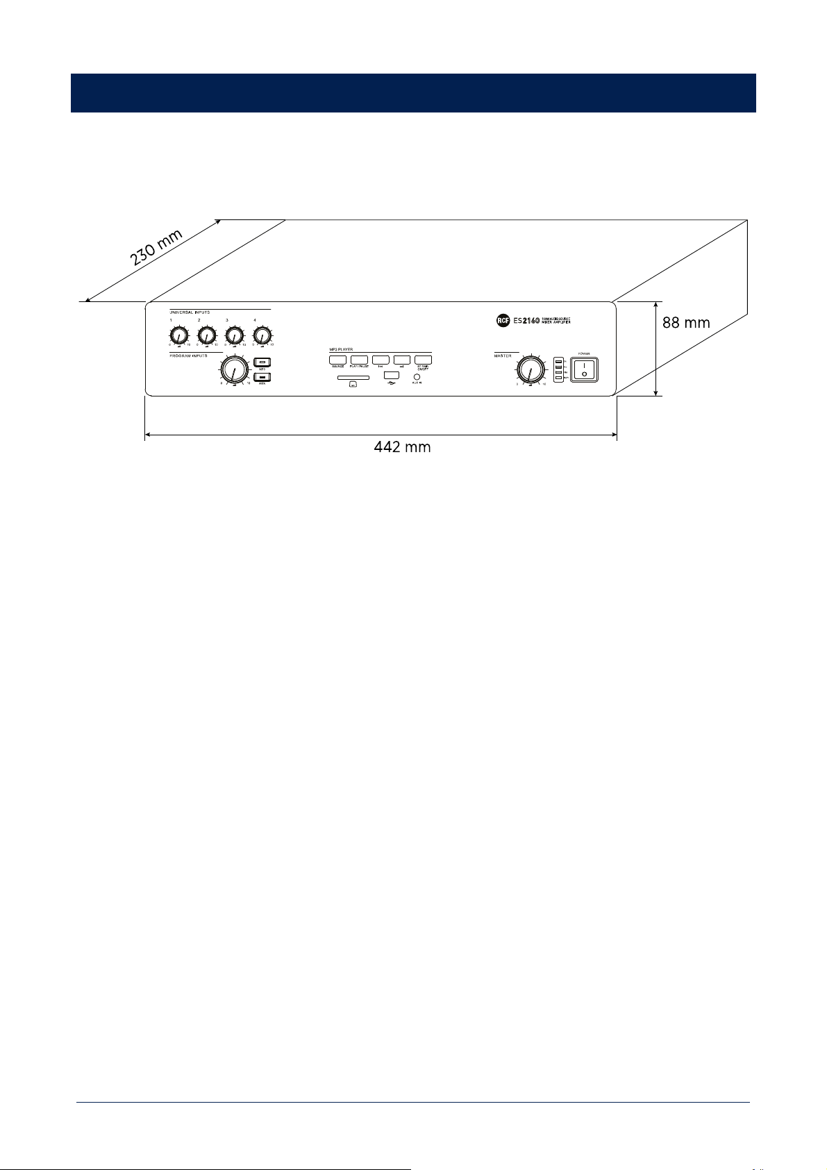
33
DIMENSIONS

34
SPECIFICATIONS
ES 2160
Amplifier specifications
Amplifier Class: D
Number of channels: 1
Power output per channel (@ 4 ohm): 160 W RMS
Power output (@ 100V): 160 W RMS
Frequency Response (-3dB): 50 Hz ÷ 14 kHz
Distortion (THD+N) @ 1 kHz nominal power: <0.3 %
Input section
Total number of inputs: 8
Balanced: 7
Unbalanced: 2
Mono: 7
Stereo: 2
Line inputs: 2
Line connectors: RCA
Mic+Line inputs: 4
Mic+Line connectors: Euroblock, XLR
Mic+Line Phantom: 32 V DC
VOX: Yes
Paging inputs: 2
Paging connectors: RJ45
Paging command: Contact
General Purpose Inputs (GPI): 2
Output section
Signal output number: 2
Signal output connectors: RCA
Power output connectors: Euroblock
Processing
Tone controls: Yes
High-pass filter: 150 Hz
Configuration: DIP switch, Front panel
Priority: Yes
Music on hold: Yes
Chime tone: Yes
Protections
Cooling: Convection
Short circuit: Yes
Thermal: Yes
DC: Yes
Fuses: Yes
Audio sources
USB pen drives: Yes
SD card: Yes
Bluetooth: Yes
Power requirement
Operating voltage: 220-240/115 V~ 50/60Hz
Voltage selection: Internal

35
ES 2160
Power consumption: 350 W
Standard compliance
CE marking: Yes
Physical specifications
Cabinet/Case Material: Metal
Colour Black
Rack mounting: 19", 2U
Size
Height: 88 mm / 3.46 inches
Width: 442 mm / 17.4 inches
Depth: 230 mm / 9.06 inches
Weight: 5.4 kg / 11.9 lbs

RCF S.p.A. Via Raffaello Sanzio, 13 - 42124 Reggio Emilia – Italy 10307730 C
Tel +39 0522 274 411 - Fax +39 0522 232 428 - e-mail: [email protected] - www.rcf.it