Loading ...
Loading ...
Loading ...

9
ENGLISH
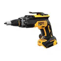
Forward/Reverse Control Button (Fig. A)
A forward/reverse control button
4
determines the
rotational direction of thetool.
• To select forward rotation (clockwise), release the trigger
and depress the forward/reverse control button on the
right side of thetool.
• To select reverse (counterclockwise), depress the
forward/reverse control button on the left side of
thetool.
NOTE: The center position of the forward/reverse
control button locks the tool in the off position when
in all screwdriving modes except "PushStart" (refer to
ModeSelection).
Proper Hand Position (Fig. H)
WARNING: To reduce the risk of serious personal
injury, ALWAYS use proper hand position as shown.
WARNING: To reduce the risk of serious personal
injury, ALWAYS hold securely in anticipation of a
suddenreaction.
Proper hand position requires one hand on the rear grip
17
.
Take care to not block the air vents
26
.
Installing and Removing the Battery Pack
(Fig. E)
WARNING: Ensure the tool/appliance is in the off
position before inserting the batterypack.
NOTE: For best results, make sure your battery pack is
fullycharged.
To install the battery pack
6
into the tool handle, align the
battery pack with the rails inside the tool’s handle and slide
it into the handle until the battery pack is firmly seated in the
tool and ensure that it does notdisengage.
To remove the battery pack from the tool, press the release
button
5
and firmly pull the battery pack out of the tool
handle. Insert it into the charger as described in the charger
section of thismanual.
OPERATION
WARNING: To reduce the risk of serious personal
injury, turn unit off and remove the battery pack
before making any adjustments or removing/
installing attachments or accessories. An
accidental start‑up can causeinjury.
Top Clip (Fig. F)
The top clip
13
can be removed if notneeded.
To remove the top clip, unscrew the two screws
14
that
hold it in place. Retain the screws in a safe place to reinstall
the topclip.
Depth Adjustment
Follow the graphic on the collar
2
to increase or decrease
the fastening depth. To seat the screw deeper in the
workpiece, turn the adjustment collar to the right. To seat the
screw higher in the workpiece, turn the adjustment collar to
theleft.
Changing Bit Tip (Fig. D)
1. Rotate the locking collar
3
1/4 turn to unlock nose cone
from gearcase.
2. Pull nose cone
4
off of gearcase.
3. Push the bit release sleeve
15
back then use pliers to
remove worn bit and install new bittip (1" #2crosshead).
Changing Bit Holders (Fig. D)
1. Rotate the locking collar
3
1/4 turn to unlock nose cone
from gearcase.
2. Pull nose cone
4
off of gearcase.
3. To remove:
a. Grab the bit holder
16
.
b. Push it into the gear case depressing the bit release
sleeve
15
.
c. Rotate the bit holder until the clutchengages.
d. While holding the sleeve depressed, pull the bit
holderout.
4. Push and rotate the new bit holder into gearcase,
depressing the sleeve, until ball lock snaps in groove in bit
holdershank.
5. Replace nose cone
4
by placing on gear case and
rotating collar 1/4 turn to align arrow on gear case with
the lock symbol oncollar.
Dead Spindle Action
All DeWALT drywall screwguns provide a dead spindle
output to permit fasteners to be located easily on the
driving accessory. Clutches are held apart by a light spring
pressure permitting the driving clutch to rotate without
turning the driven clutch and accessory. When sufficient
forward pressure is applied to the unit, the clutches engage
and rotate the spindle and accessories. A reversing switch
makes it possible to drive or loosen either right or left
handfasteners.
ASSEMBLY AND ADJUSTMENTS
WARNING: To reduce the risk of serious personal
injury, turn unit off and remove the battery pack
before making any adjustments or removing/
installing attachments or accessories. An
accidental start‑up can causeinjury.
Wall Mounting
Some DeWALT chargers are designed to be wall mountable
or to sit upright on a table or work surface. If wall mounting,
locate the charger within reach of an electrical outlet, and
away from a corner or other obstructions which may impede
air flow. Use the back of the charger as a template for the
location of the mounting screws on the wall. Mount the
charger securely using drywall screws (purchased separately)
at least 1” (25.4mm) long, with a screw head diameter of
0.28–0.35” (7–9mm), screwed into wood to an optimal
depth leaving approximately 7/32” (5.5 mm) of the screw
exposed. Align the slots on the back of the charger with the
exposed screws and fully engage them in theslots.
SAVE THESE INSTRUCTIONS FOR
FUTURE USE
Loading ...
Loading ...
Loading ...