
Loading ...
Loading ...
Loading ...
English
14
3. While depressing the spindle lock button, thread the clamp nut
(I) on spindle.
4. While depressing the spindle lock button, tighten the clamp nut
with a wrench.
5. To remove the wheel, depress the spindle lock button and loosen
the threaded clamp nut with a wrench.
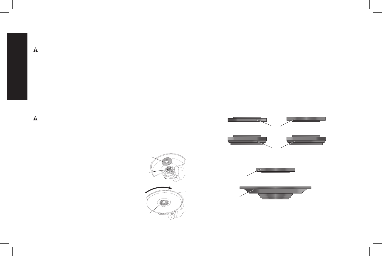
NOTE: If the wheel spins after the clamp nut is tightened, check the
orientation of the threaded clamp nut. If a thin wheel is installed with
the pilot on the clamp nut against the wheel, it will spin because the
height of the pilot prevents the clamp nut from holding the wheel.
Wheels thicker than
1/8" (3.17mm)
Type 1/41 Wheels
1/8" (3.17mm) and thinner
6" Type 27 depressed center wheels
FIG. 15
H
L
I
I
Mounting and Using Depressed Center
Grinding Wheels and Sanding Flap Discs
CAUTION: A Type 27 guard must be used.
MOUNTING AND REMOVING HUBBED WHEELS
Hubbed wheels install directly on the 5/8"-11 threaded spindle.
Thread of accessory must match thread of spindle.
1. Backing flange is retained to the grinder by an O-ring on the
spindle. Remove backing flange by pulling and twisting flange
away form the machine.
2. Thread the wheel on the spindle by hand.
3. Depress the spindle lock button and use a wrench to tighten the
hub of the wheel.
4. Reverse the above procedure to remove the wheel.
CAUTION: Failure to properly seat the wheel before turning the
tool on may result in damage to the tool or the wheel.
MOUNTING NON-HUBBED WHEELS (FIG. 14, 15)
Depressed center Type 27 grinding wheels must be used with
included flanges.
NOTE: The 3" (76 mm) diameter stamped
steel backing flange (L) is ONLY for use with
6" (152 mm) Type 27 grinding wheels. Refer
to the Accessory Chart for more information.
1. Install the 3" (76 mm) diameter stamped
steel backing flange (L) for 6" (152 mm).
Be sure the backing flange recess is seated
onto the flats of the spindle by pushing and
twisting the flange before placing wheel.
2. Place wheel against the backing flange,
centering the wheel on the raised section
(pilot) of the backing flange.
L
W
I
FIG. 14
Loading ...
Loading ...
Loading ...