
Loading ...
Loading ...
Loading ...
English
12
repairs. Before reconnecting the tool, depress and release
the paddle or trigger switch to ensure that the tool is off. An
accidental start-up can causeinjury.
Switches
CAUTION: Hold the side handle and body of the tool firmly to
maintain control of the tool at start up and during use and until the
wheel or accessory stops rotating. Make sure the wheel has come to
a complete stop be fore laying the tool down.
NOTE: To reduce unexpected tool movement, do not switch the
tool on or off while under load conditions. Allow the grinder to run
up to full speed before touching the work surface. Lift the tool from
the surface before turning the tool off. Allow the tool to stop rotating
before putting it down.
SOFT START FEATURE
The soft start feature allows a slow speed build-up to avoid an initial
jerk when starting. This feature is particularly useful when working in
confined areas. Current surge will also be reduced.
PADDLE SWITCH OPERATION
(DWE46044) (FIG. 10)
To turn the tool on, push the lock-off
A
C
FIG. 10
lever (C) toward the back of the tool,
then depress the paddle switch (A). The
tool will run while the switch is
depressed. Turn the tool off by releasing
the paddle switch.
Before using the tool, check that the handle is tightened se cure ly. Use
a wrench to firmly tighten the side handle.
Gear Case Orientation
DWE46044 and DWE46066 are sold with the spindle-side of the gear
case facing to the left relative to the switch or trigger facing down.
This position is ideal for cutting applications. The gear case can be
repositioned to a different orientation if preferred by the user.
CAUTION: Do not reposition the gear case when using the stock
adjustable cut-off guard.
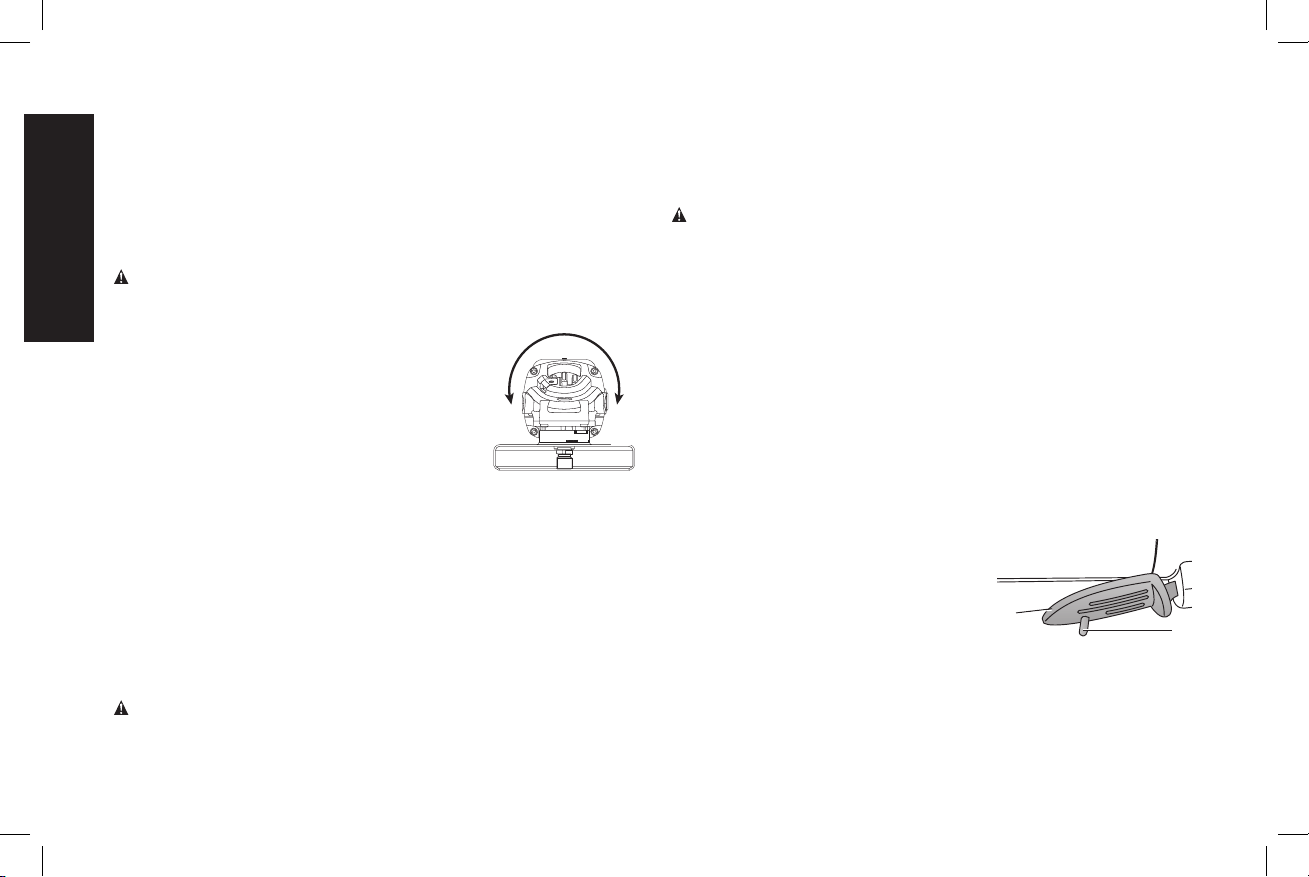
ROTATING THE GEAR CASE (FIG. 9)
1. Remove guard and flanges from tool.
2. Remove the four corner screws attaching
the gear case to motor housing.
3. Separating the gear case from motor
housing not more than 1/4" (6.35 mm),
rotate the gear case head to desired
position.
NOTE: If the gear case and motor housing become separated
by more than 1/4" (6.35 mm), the tool must be serviced and
re-assembled by a D
e
WALT service center. Failure to have the tool
serviced may cause brush, motor and bearing failure.
4. Re-install screws to attach the gear case to the motor housing.
Tighten screws to 18 in./lbs. (2.03 Nm) torque. Overtightening
could cause screws to strip.
5. Re-install guard and correct flanges for the appropriate
accessories.
OPERATION
WARNING: To reduce the risk of injury, turn unit off and
disconnect it from power source before installing and
removing accessories, before adjusting or when making
90˚
90˚
FIG. 9
Loading ...
Loading ...
Loading ...