
Loading ...
Loading ...
Loading ...
English
10
• Be sure the backing and threaded locking flange are
mounted correctly. Follow the instructions given in the
AccessoriesChart.
• Make sure the disc or wheel rotates in the direction of
the arrows on the accessory and thetool.
• Do not use a damaged accessory. Before each use
inspect the accessory such as abrasive wheels for chips
and cracks, backing pad for cracks, tear or excess wear,
wire brush for loose or cracked wires. If power tool or
accessory is dropped, inspect for damage or install an
undamaged accessory. After inspecting and installing
an accessory, position yourself and bystanders away
from the plane of the rotating accessory and run the
power tool at maximum no-load speed for one minute.
Damaged accessories will normally break apart during
this testtime.
OPERATION
WARNING: To reduce the risk of serious personal
injury, turn unit off and disconnect it from
power source before making any adjustments or
removing/installing attachments or accessories.
An accidental start-up can causeinjury.
Proper Hand Position (Fig. G)
WARNING: To reduce the risk of serious personal
injury, ALWAYS use proper hand position as shown.
WARNING: To reduce the risk of serious personal
injury, ALWAYS hold securely in anticipation of a
suddenreaction.
Proper hand position requires one hand on the side
handle
5
, with the other hand on the body of the tool, as
shown in FigureG.
Fig. G
5
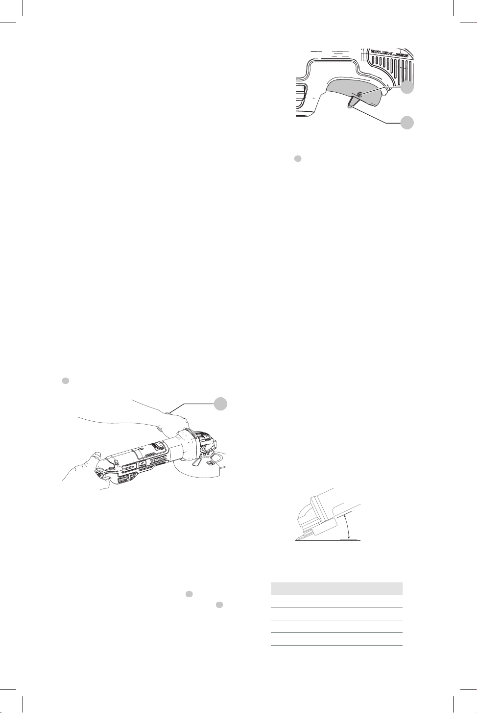
Trigger Switch and Lock-off Lever (Fig. H)
WARNING: Before using the tool, check that the side
handle is tightenedsecurely.
CAUTION: Hold the side handle and body of the tool
firmly to maintain control of the tool at start up and
during use and until the wheel or accessory stops
rotating. Make sure the wheel has come to a complete
stop be fore laying the tooldown.
1. To turn the tool on, push the lock-off lever
9
toward
the back of the tool, then depress the trigger switch
8
.
The tool will run while the switch isdepressed.
2. Turn the tool off by releasing the releasingswitch.
WARNING: Allow the tool to reach full speed before
touching tool to the work surface. Lift the tool from
the work surface before turning the tooloff.
Fig. H
8
9
Spindle Lock (Fig. A)
The spindle lock
2
is provided to prevent the spindle from
rotating when installing or removing wheels. Operate the
spindle lock only when the tool is turned off, unplugged
from the power supply, and has come to a completestop.
NOTICE: To reduce the risk of damage to the tool, do
not engage the spindle lock while the tool is operating.
Damage to the tool will result and attached accessory
may spin off possibly resulting ininjury.
To engage the lock, depress the spindle lock button
and rotate the spindle until you are unable to rotate the
spindlefurther.
Surface Grinding, Sanding and Wire
Brushing (Fig. I)
CAUTION: Always use the correct guard per the
instructions in thismanual.
WARNING: Metal dust build-up. Extensive use
of flap discs in metal applications can result in the
increased potential for electric shock. To reduce
this risk, insert an RCD before use and clean the
ventilation slots daily by blowing dry compressed air
into the ventilation slots inaccordance with the below
maintenanceinstructions.
To perform work on the surface of a workpiece:
1. Allow the tool to reach full speed before touching the
tool to the worksurface.
2. Apply minimum pressure to the work surface, allowing
the tool to operate at high speed. Material removal rate
is greatest when the tool operates at highspeed.
Angle
Fig. I
3. Maintain an appropriate angle between the tool
and work surface. Refer to the chart according to
particularfunction.
Function Angle
Grinding 20˚-30˚
Sanding with Flap Disc 5˚-10˚
Sanding with Backing Pad 5˚-15˚
Wire Brushing 5˚-10˚
4. Maintain contact between the edge of the wheel and
the worksurface.
Loading ...
Loading ...
Loading ...