
Loading ...
Loading ...
Loading ...
Maintenance and
Disassembly
Page 47
Procedure Illustration
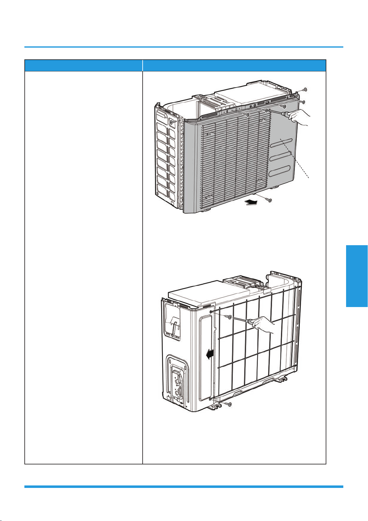
4) Remove the screws of the front panel
and then remove the front panel (7
screws) (see CJ_BA30_INV_003).
5) Remove the screws of the rear net and
then remove the rear net (2 screws)
(see CJ_BA30_INV_004).
CJ_BA30_INV_003
CJ_BA30_INV_004
Note: This section is for reference only. Actual unit appearance may vary.
Front Panel
Loading ...
Loading ...
Loading ...