
Loading ...
Loading ...
Loading ...
Maintenance and
Disassembly
Page 37
Procedure Illustration
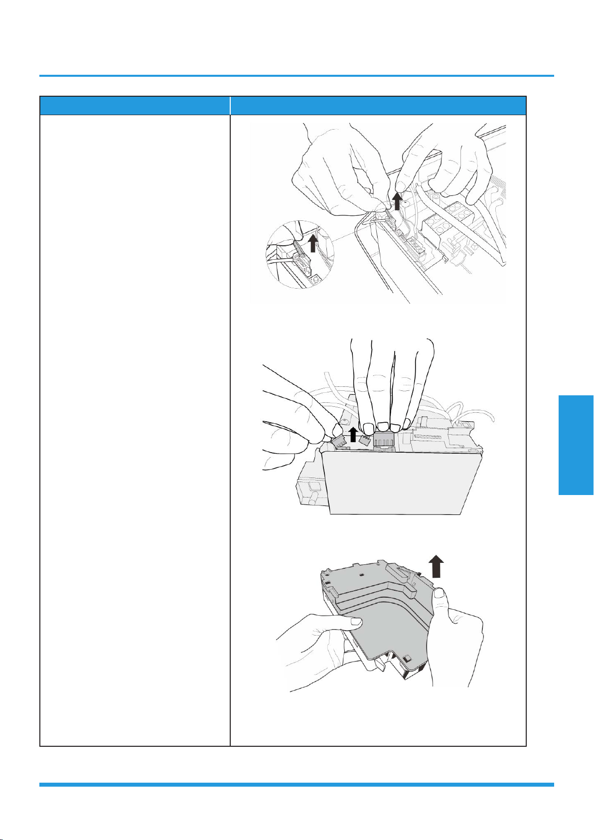
4) Remove the fixed devices of the
connectors (see CJ_AB_INV_016).
5) Disconnect the connectors of fan
motor, the step motor and the T2
sensor (see CJ_AB_INV_017).
6) Open the left side plate of electronic
control box (see CJ_AB_INV_018).
CJ_AB_INV_016
CJ_AB_INV_017
CJ_AB_INV_018
Note: This section is for reference only. Actual unit appearance may vary.
CJ_AF_INV_011-1
Loading ...
Loading ...
Loading ...