
Loading ...
Loading ...
Loading ...
Maintenance and
Disassembly
Page 35
Procedure Illustration
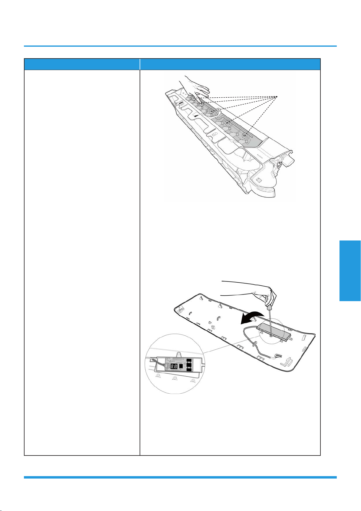
12) Release the 5 hooks of the vertical
blades, then pull the vertical blades
rightward and remove it (see CJ_AB_
INV_012).
13) Remove 1 screw of the display board.
(see CJ_AB_INV_013).
14) Rotate the display board in the
direction shown in the right picture.
(see CJ_AB_INV_013).
CJ_AB_INV_012
CJ_AB_INV_013
Note: This section is for reference only. Actual unit appearance may vary.
Hooks
Loading ...
Loading ...
Loading ...