Loading ...
Loading ...
Loading ...
6
4. Installation
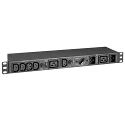
Plug Computer into Controllable Output Receptacle
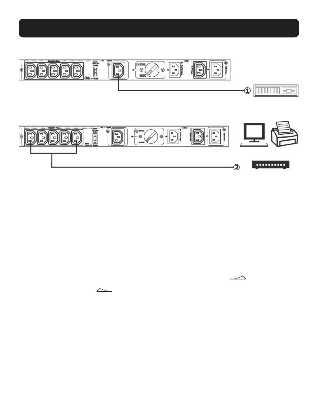
Plug Peripherals into Controllable Output Receptacle Group
Normal/Bypass Mode Operation
Before transferring to maintenance bypass, make sure the Main Power LED is illuminated. Transfer the rotary bypass switch
from NORMAL to BYPASS. At this time, the Bypass Mode LED will illuminate and all connected devices will be powered by
utility power directly. You may turn off the UPS and disconnect two cables connecting to the UPS. You may now service or
replace the UPS.
Transfer to UPS Protection
After maintenance service is complete, ensure the UPS operation is normal. Reconnect the UPS to the unit by following the
steps in section 4. Installation. Verify the Main Power LED is illuminated. Then transfer the rotary bypass switch from BYPASS
to NORMAL. All connected devices are now protected by the UPS.
ECO Mode Function Operation
After connecting all devices to the unit, press the ECO Mode function switch to ENABLE status ( ). The Controllable
Receptacle Group LED will illuminate when the connected load on the master output is above 20W. Press the ECO Mode
function switch to DISABLE status ( ) to disable the function. The Controllable Receptacle Group LED will be illuminated.
Monitor Printer
Switch
Computer
Loading ...
Loading ...
Loading ...