Loading ...
Loading ...
Loading ...
5
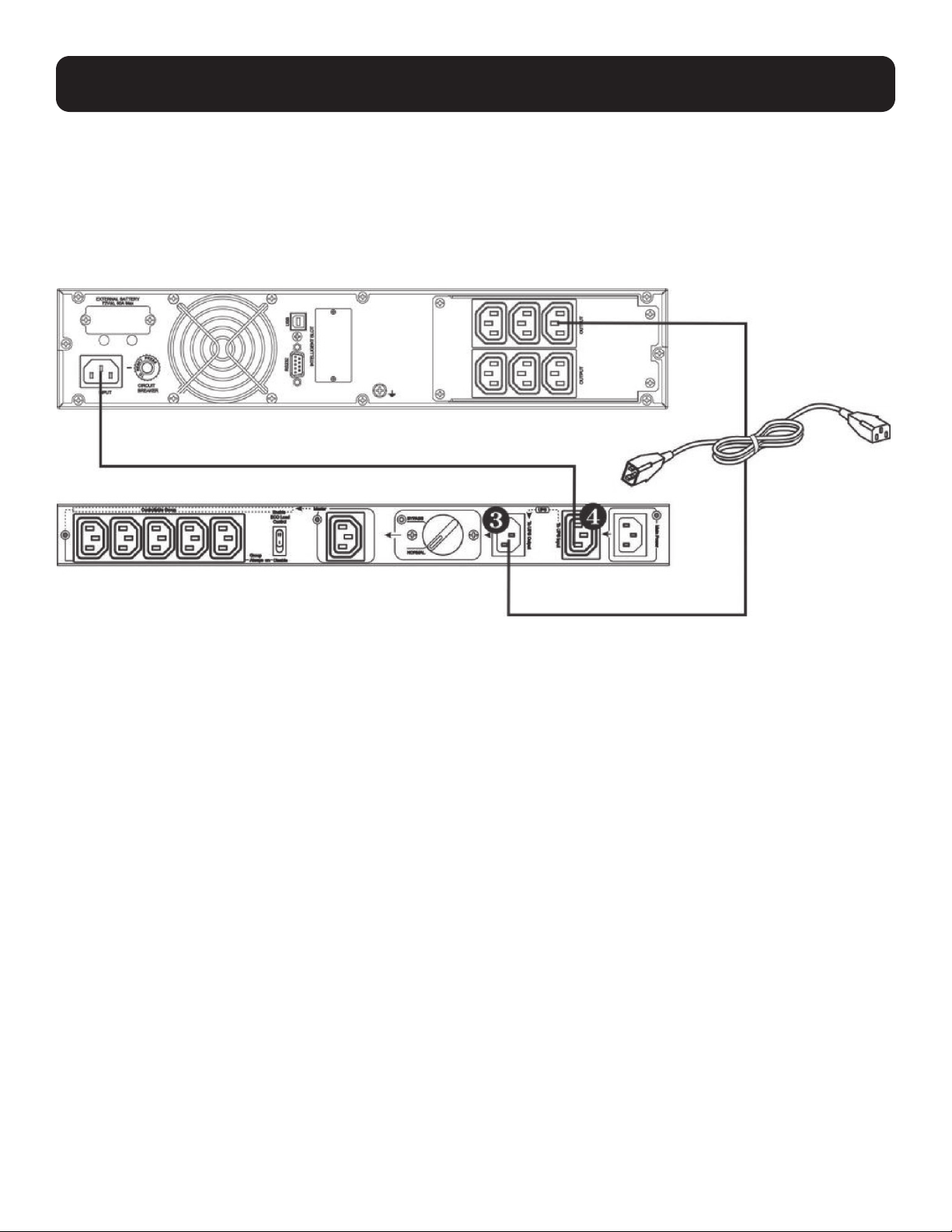
Connect UPS
1. Connect the UPS input cord to the outlet for UPS input power cord (4). This outlet is labeled “To UPS Input” on the
Bypass PDU.
2. Connect the protected UPS input power connection on the Bypass PDU to a protected UPS outlet. This connection is
labeled “To UPS Output” on the bypass PDU.
Note: For models PDUBHV101U and PDUBHV201U, use the supplied power cords to make these connections.
Protected UPS Input Power Connection
Connect Equipment
There are two types of outputs: Master and Controllable Group receptacles. Outlet functions are controlled by the ECO load
control switch. When this switch is set to DISABLE, all outlets will operate in an always-on capacity. In this configuration,
protected equipment can be connected to any outlet whether it is part of the Master or Controllable Group set of outlets for
always-on operation during both Normal and Bypass Modes.
When the ECO load control switch is set to ENABLE, the device connected to the load-sensing Master outlet will offer
automatic power OFF/ON control of the set of Controllable Group outlets. In this configuration, powering off the device
connected to the Master outlet will automatically power off the devices connected to the Controllable Group outlets. Anytime
the Master outlet current is measured to be 20W or less, the Controllable Group outlets will power off within 1 second.
4. Installation
Loading ...
Loading ...
Loading ...