Loading ...
Loading ...

3
1
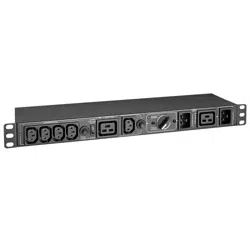
Master Output Receptacle(s)
UPS-supported outlet with optional current sense capability. This connection is labeled MASTER on the Bypass PDU.
2
Controllable Output Receptacle Group
UPS-supported outlets with optional power switching capability. These connections are labeled CONTROLLABLE GROUP on
the Bypass PDU.
3
Protected UPS Input Power Connection
Connect to a protected UPS output receptacle. This connection is labeled TO UPS OUTPUT on the Bypass PDU.
4
Outlet for UPS Input Power Cord
Connect the UPS input cord here. This connection is labeled TO UPS INPUT on the Bypass PDU.
5
Bypass Switch
Set switch to NORMAL for standard protected UPS operation. Set switch to BYPASS during UPS replacement.
6
Mains AC Inlet/Cord
Connect AC input cord to any compatible mains power source. This connection is labeled MAIN POWER on the Bypass PDU.
7
Circuit Breaker (select models)
8
Enable ECO Load Control Switch
Select DISABLE for always-on operation of controllable outlets. Select ENABLE for optional ECO load-switching capability.
LED Indicators
A
Mains AC Input (Green)
Illuminates to indicate mains AC cord/inlet (6) is live.
B
Controllable Receptacle Group Output (Green)
Illuminates to indicate Controllable Receptacle Group (2) is live.
C
Master Output Receptacle Output (Green)
Illuminates to indicate Master Output Receptacle (1) is live.
D
Bypass Mode LED (Yellow)
Illuminates when the Bypass Switch is in the BYPASS position.
2. Product Overview
Loading ...
Loading ...
Loading ...