Loading ...
Loading ...
Loading ...
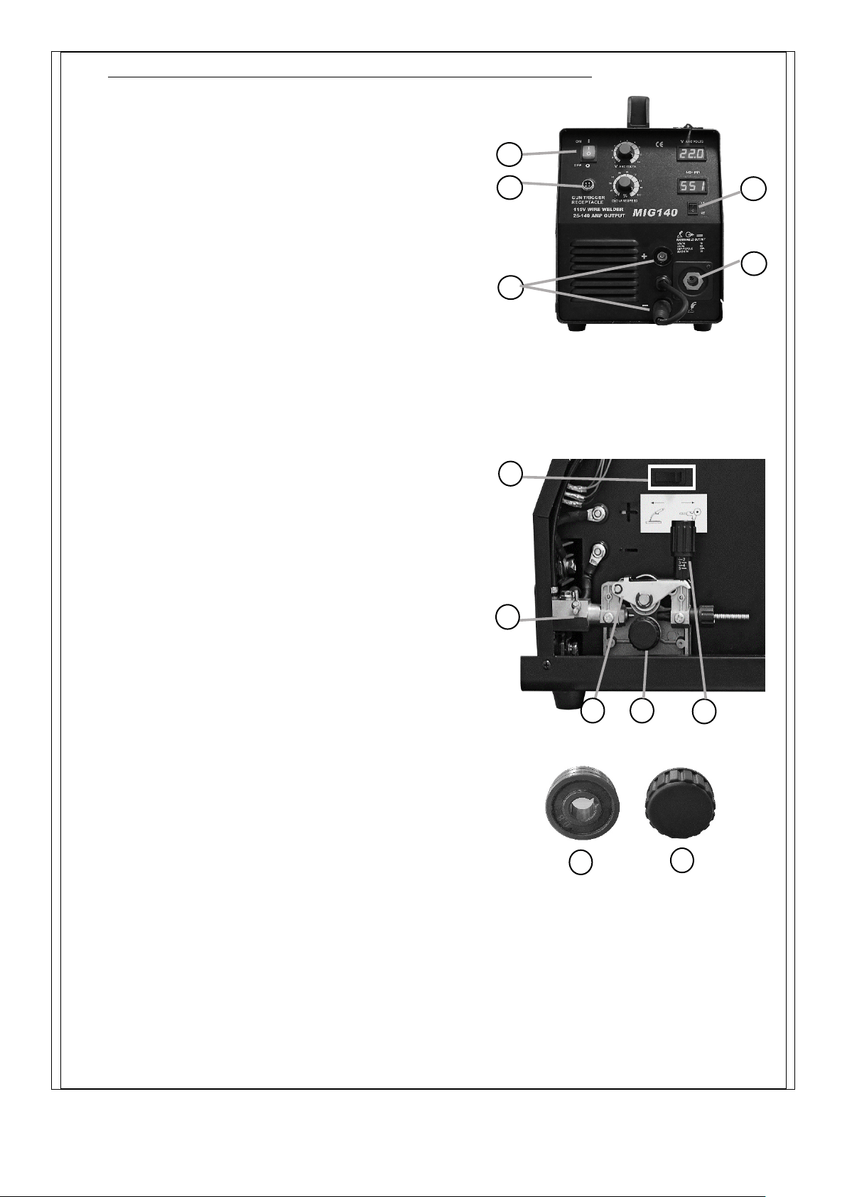
CONNECT THE WELDING GUN TO THE WELDING MACHINE
Power off the welding machine (switch is
positioned at “O”)
○
1 .
Plug the welding gun into the Gun Trigger
Lead Connectors hole and plug it into to the
connector block. Also, thread the control wire
of the welding gun through the access
hole
○
2 and inset the control wire into the gun
trigger connector terminals
○
3 .
Tighten the wing screw
○
6 attached to the
connector block of the wire feed gearbox.
Make sure the Gun changing switch
○
9 is in
the correct position MIG for standard welding
and Spool Gun if optional gun is installed.
WIRE DRIVE ROLL INSTALLATION
The reversible dual groove wire drive roll attached
to MIG140 has two wire grooves; One for .025”
(0.6mm) solid welding wire and the other
for .030-.035” (0.8-0.9mm) solid or flux-cored
welding wire. The factory default installation
is .025” (0.6mm).
Ensure that the MIG140 welding machine is
powered off.
Unlatch the spring loaded pressure arm and open the idle roll
arm
○
9 and lift up the idle roll arm
○
6 .
Loosen the plastic screw
○
11 that attaches the wire drive roll.
In the event that .030” (0.8mm) - .035” (0.9mm) welding wires
are used
Remove the wire drive roll
○
10 and flip the wire drive roll
over so that the .025” (0.6mm) mark faces the user.
In the event that .026” (0.6mm) welding wires are used
Remove the wire drive roll
○
10 and flip the wire drive roll
over so that the .030” (0.8mm) mark faces the user.
Reinstall by putting back the wire drive roll and tighten the
plastic screw.
2
4
3
1
5
9
6
7
8
9
Figure C-1
Figure C-2
Figure C-3
10
11
Loading ...
Loading ...
Loading ...