Loading ...
Loading ...
Loading ...

English
11
negative (–) cable post. Replace the cap and turn clockwise to
secure. Do not over-tighten.
5. Connect the black battery clip to the NEGATIVE terminal of the
battery.
6. Make sure that all connections between cables and terminals are
secure.
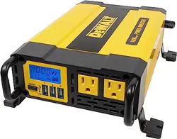
7. Press the power button to turn the inverter on. A beep will sound,
the backlit LCD and the USB power/fault indicators will activate
to indicate the inverter is operating properly and the 120 volt AC
outlets are ready to power appliances that draw up to 1000W
continuous and USB outlets up to 3.1A.
Note: Refer to “Power and Fault Indicators on the LCD Display” for
an explanation of the operating and fault icons. If a fault icon appears,
refer to the “Protective Features” section and the “Troubleshooting”
section of this manual.
DIRECT HARDWIRING TO POWER SOURCE (OPTIONAL
CONNECTION METHOD; HARDWARE NOT INCLUDED)
Use #8 AWG wire if the inverter to power source connection is 4 feet
or less. For cable lengths up to 10ft use #6 AWG wire.* In either case,
protect the positive (+) wire from shorts by installing a 150 amp fuse
or circuit breaker close to the DC power source (battery) terminal.
The cable, fuse holder and fuse (not supplied) can be purchased at
an electrical supply company. Manufacturer provides the installation
cable set (refer to the “Installation” section of this manual).
*For cable lengths exceeding 10 feet from inverter to battery, contact
manufacturer for additional information.
1. Check to make sure that the inverter is turned off and no flammable
fumes are present in the installation area.
2. Identify the positive (+) and negative (–) DC power source (battery)
terminals.
3. Install a fuse holder or breaker close to the positive (+) terminal of
the DC source (battery).
4. Connect a length of wire on one side of the fuse holder or circuit
breaker. Connect the other end of the wire to the positive (+, red)
O-ring of the supplied cable set, securing them using the supplied
bolt, washer and the wing nuts.
5. Connect a length of wire on one side of the negative (–) DC power
source (battery) terminal. Connect the other end of the wire to the
negative (–, black) O-ring of the supplied cable set, securing them
using the supplied bolt, washer and the wing nuts.
6. Connect a short length of wire to the other terminal of the fuse
holder or circuit breaker. Mark it “positive” or “+”.
7. Connect the free end of the fuse or breaker wire to the positive (+)
terminal of the DC power source (battery).
8. Insert a fuse appropriate to the inverter in the fuse holder.
9. Check to make sure the power button is turned off.
10. Turn the red plastic cap on the inverter’s positive (+) cable post
(counterclockwise) and remove. Attach the positive slide-in
connector at the end of the supplied red cable set into the groove
of the positive (+) cable post. Replace the cap and turn clockwise
to secure. Do not over-tighten.
11. Turn the black plastic cap on the inverter’s negative (–) cable
post (counterclockwise) and remove. Attach the negative slide-in
connector at the end of the supplied black cable set into the groove
of the negative (–) cable post. Replace the cap and turn clockwise
to secure. Do not over-tighten.
12. Make sure that all connections between cables and terminals are
secure.
13. Press the power button to turn the inverter on. A beep will sound,
the backlit LCD and the USB power/fault indicators will activate
to indicate the inverter is operating properly and the 120 volt AC
outlets are ready to power appliances that draw up to 1000W
continuous and USB outlets up to 3.1A. Refer to “Power and Fault
Indicators on the LCD Display” for an explanation of the operating
Loading ...
Loading ...
Loading ...