Loading ...
Loading ...
Loading ...

English
9
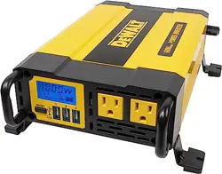
Indicates that the unit is functioning
normally. The AC outlet icon and USB
icon will light solid and the Digital
Readout shows the total output wattage
of AC outlets. The bars on the Battery
Icon represent the voltage level of the
connected power source.
This indicates an input voltage too low
fault condition. The fault icon and the
empty battery icon will light solid and
the unit will emit three beeps every five
seconds. Refer to the following section
for an explanation.
This indicates an input voltage too high
fault condition. The fault icon and the full
battery icon will light solid and the unit
will emit three beeps every five seconds.
Refer to the following section for an
explanation.
This indicates a thermal fault condition.
The fault icon and the overheat icon will
light solid and the bars on the Battery
Icon represent the voltage level of the
connected power source. The unit will
emit three beeps every five seconds.
Refer to the following section for an
explanation.
This indicates a USB fault condition, and
displays when the USB load exceeds
capacity. The USB icon will flash and the
Digital Readout shows the total output
wattage of AC outlets. The fault icon and
the AC outlet icon will light solid and the
bars on the Battery Icon represent the
voltage level of the connected power
source. The unit will emit three beeps
every five seconds.
This indicates an overload or short circuit
fault condition. The AC outlet icon will
flash and the Digital Readout shows
0W. The fault icon and the USB icon will
light solid and the bars on the Battery
Icon represent the voltage level of the
connected power source. The unit will
emit three beeps every five seconds.
Refer to the following section for an
explanation.
Installation
Your inverter will provide you with continuous electrical power when
powered by a reliable 12 volt DC source, such as a vehicle battery or
a multiple battery configuration. This manual does not describe all of
the possible configurations.
Mounting the Inverter
Tools Required: four BA4x14 screws in a set and Philips head
screwdriver (NOT supplied).
The inverter comes equipped with mounting brackets for long-term
installation. The manufacturer recommends using BA4x14 screws
Loading ...
Loading ...
Loading ...