Loading ...
Loading ...
Loading ...
14
SERVICING
WARNING:
Servicing should be carried out only by
authorised personnel.
10) COMPONENTS REPLACEMENT
NOTE:
BEFORE ANY MAINTENANCE REQUIRING
REPLACEMENT OF A COMPONENT IS
UNDERTAKEN ENSURE THAT THE
ELECTRICAL LEAD HAS BEEN ISOLATED AND
REMOVED FROM THE POWER POINT.
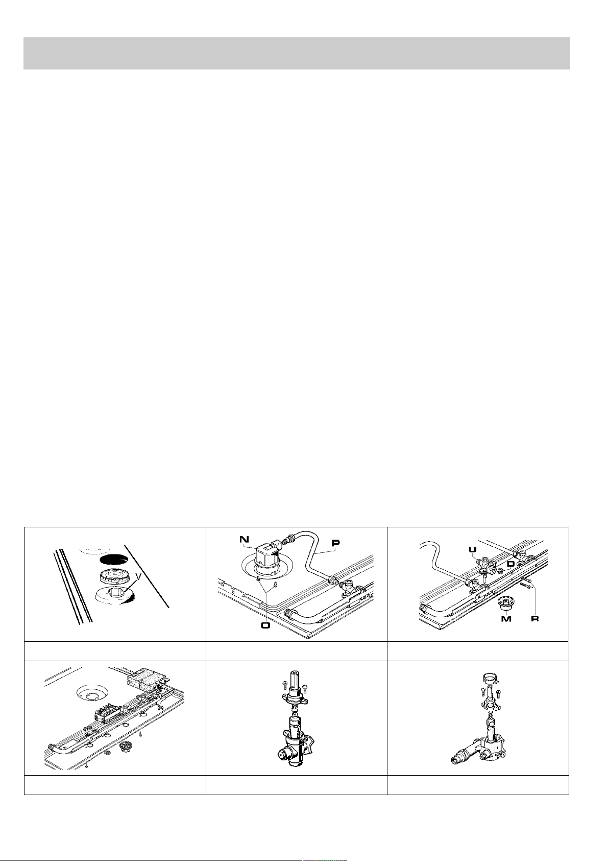
To replace the components fit inside the hob is
necessary to take off the pan supports and the
burners from the upper part of the working table, then
unscrew the burner fixing screws “V” (fig. 16) and the
control knobs, fixed by a simple pressure, in order to
take off the working table.
After having carried out the above listed operations,
the burners (fig. 17), taps (fig. 18) and electrical
components can all be replaced (fig. 19).
It is advisable to change seal “D” each time a tap is
changed in order to ensure a perfect tightness.
Greasing the taps (see fig. 20 - 21)
If a tap becomes stiff to operate, it must be
immediately greased in compliance with the
following instructions:
- Remove the tap.
- Clean the cone and its housing using a cloth
soaked in solvent.
- Lightly spread the cone with the relative grease.
- Fit the cone back in place, operate it several times
and then remove it again. Eliminate any excess
grease and check that the gas ducts have not
become clogged.
- Fit all parts back in place, complying with the
demounting order in reverse.
- Ceck the tightness by using soapy water. The use
of the flame is prohibited.
To facilitate the servicing technician’s task, here is a
chart with the types and sections of the powering
cables and the ratings of the electrical components.
FIG. 19 FIG. 20 FIG. 21
FIG. 16 FIG. 17 FIG. 18
Loading ...
Loading ...
Loading ...