Loading ...
Loading ...
Loading ...
9
1. It is essential that the gas supply is correct for the appliance being installed and that adequate
supply pressure and volume are available. The following checks should be made before installation:-
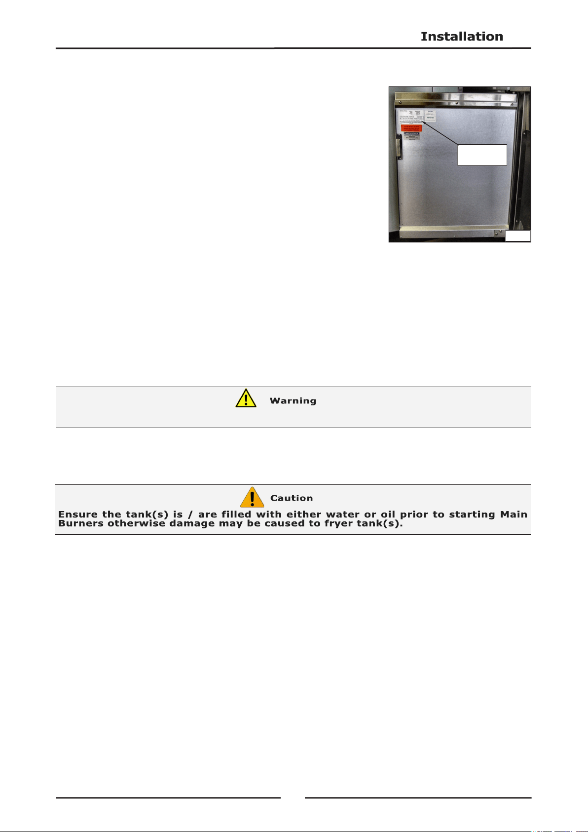
a. Gas Type appliance has been supplied for is shown on a
coloured sticker located above gas entry point and next to
rating plate. Check that this is correct for gas supply appliance
is being installed for. Gas conversion procedure is shown in
this manual.
b. Supply Pressure required for this appliance is shown in the
Specifications section of this manual. Check gas supply to
ensure that adequate supply pressure exists.
c. Input Rate of this appliance is shown on Rating Plate fitted to
inside of access door and in Specifications' section of this
manual. Input rate should be checked against available gas
supply line capacity. Particular note should be taken if
appliance is being added to an existing installation.
NOTE: It is important that adequately sized piping runs directly to the connection joint on the
appliance, with as few tees and elbows as possible to give maximum supply volume.
2. A suitable joining compound which resists the breakdown action of LPG must be used on every gas
line connection, unless compression fittings are used.
Connection to appliance is
3
/
4
” BSP male.
NOTE: A Manual Isolation Valve must be fitted to individual appliance supply line.
3. Correctly locate appliance into its final operating position and using a spirit level, adjust legs so that
unit is level and at correct height.
4. Connect gas supply to appliance.
5. Check all gas connections for leakages using soapy water or other gas detecting equipment.
6. Check gas supply pressure is as shown in Specifications section, Gas Supply Requirements table.
NOTE: Measure gas supply pressure at upper test point (Supply Pressure Test Point) on gas
control valve.
7. Light Pilot Burners. Refer to Operation section, Lighting Pilot Burners.
8. Check pilot flame size. Re-adjust if required, using pilot adjusting screw (See Fig 2 overleaf), and as
shown in Gas Conversion and Specifications section, Pilot Burner Flame Adjustment.
9. Light Main Burners. Refer to Operation section, Lighting Main Burners.
Rating Plate
Location
Fig 1
DO NOT USE A NAKED FLAME TO CHECK FOR GAS LEAKAGES.
Loading ...
Loading ...
Loading ...