Register
your product
www.kaercher.com/welcome
KM 105/100 R Bp (Pack)
KM 105/110 R Bp (Pack)
KM 125/130 R Bp (Pack)
001
59990870 06/22

-
1
Please read and comply with
these original instructions prior
to the initial operation of your appliance and
store them for later use or subsequent own-
ers.
Please read the safety instructions before
start-up!
The devices listed below are described in
these operating instructions.
The devices differ in working width as well
as in the type of waste emptying, also refer
to Chapter "Technical data".
Appliance configuration
For all appliances the same features are
optionally available. This manual describes
the maximum features.
Waste disposal
There are 2 different options for waste dis-
posal:
Low emptying system
These devices have two waste containers
in the back that must be removed to empty
them.
Lift/tilt emptying mechanism
These devices have a waste container that
is operated from the driver seat for empty-
ing.
Your sales outlet should be informed about
any transit damage noted when unpacking
the product.
– Warning and information plates on the
machine provide important directions
for safe operation.
– In addition to the information contained
in the operating instructions, all statuto-
ry safety and accident prevention regu-
lations must be observed.
Notes about the ingredients (REACH)
You will find current information about the
ingredients at:
www.kaercher.com/REACH
The warranty terms published by the rele-
vant sales company are applicable in each
country. We will repair potential failures of
your appliance within the warranty period
free of charge, provided that such failure is
caused by faulty material or defects in man-
ufacturing. In the event of a warranty claim
please contact your dealer or the nearest
authorized Customer Service center.
Please submit the proof of purchase.
� DANGER
To avoid risks, all repairs and replacement
of spare parts may only be carried out by
authorized customer service personnel.
– Only use accessories and spare parts
which have been approved by the man-
ufacturer. The exclusive use of original
accessories and original spare parts
ensures that the appliance can be oper-
ated safely and trouble free.
– At the end of the operating instructions
you will find a selected list of spare
parts that are often required.
– For additional information about spare
parts, please go to the Service section
at www.kaercher.com.
Contents
Contents . . . . . . . . . . . . . . . . . EN 1
General notes . . . . . . . . . . . . . EN 1
Environmental protection EN 1
Warranty . . . . . . . . . . . . EN 1
Accessories and Spare
Parts. . . . . . . . . . . . . . . . EN 1
Symbols in the operating in-
structions . . . . . . . . . . . . EN 2
Symbols on the machine EN 2
Proper use . . . . . . . . . . . . . . . . EN 2
Foreseeable misuse. . . . EN 2
Suitable surfaces . . . . . . EN 2
Safety instructions . . . . . . . . . . EN 3
Safety instructions concern-
ing the operation . . . . . . EN 3
Operations . . . . . . . . . . . EN 3
Safety information concern-
ing the driving operation. EN 3
Appliances with high empty-
ing system . . . . . . . . . . . EN 3
Devices with overhead
guard . . . . . . . . . . . . . . . EN 3
Safety information concern-
ing the transport of the appli-
ance . . . . . . . . . . . . . . . . EN 3
Safety information concern-
ing maintenance and care EN 3
Function. . . . . . . . . . . . . . . . . . EN 3
Operating and Functional Ele-
ments. . . . . . . . . . . . . . . . . . . . EN 4
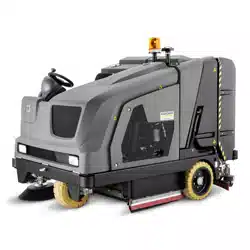
Device view KM 105/
100(110) R. . . . . . . . . . . EN 4
Device view KM 125/130 R EN 5
Operating field . . . . . . . . EN 6
KIK-key (Kärcher Intelligent
Key) yellow/grey. . . . . . . EN 6
Program selection switch EN 7
Safety Devices. . . . . . . . EN 7
Parking brake. . . . . . . . . EN 7
Before Startup . . . . . . . . . . . . . EN 7
Remove the appliance coverEN 7
Opening/closing cover on
the left . . . . . . . . . . . . . . EN 7
Unloading tips . . . . . . . . EN 8
Install side brush . . . . . . EN 8
Notes regarding the battery . . . EN 8
Safety notes regarding the
batteries . . . . . . . . . . . . . EN 8
Check and correct the fluid
level of the battery (only for
low-maintenance batteries) EN 9
Recommended batteries,
chargers. . . . . . . . . . . . . EN 9
Installing and connecting the
batteries . . . . . . . . . . . . . EN 9
Charging battery . . . . . . EN 9
Start up . . . . . . . . . . . . . . . . . . EN 10
Prior to start/safety test . EN 10
Operation. . . . . . . . . . . . . . . . . EN 10
Adjusting driver's seat . . EN 10
Storage area . . . . . . . . . EN 10
Starting up the appliance EN 10
Drive the machine . . . . . EN 11
Sweeping mode . . . . . . . EN 11
Emptying waste container EN 12
Display message >Charge
battery!< (KM 105/... R Bp
and KM 105/...R Bp Pack) EN 12
Turn off the appliance . . EN 12
Transport . . . . . . . . . . . . EN 13
Storage . . . . . . . . . . . . . EN 13
Shutdown . . . . . . . . . . . . . . . . EN 13
Care and maintenance . . . . . . EN 13
General notes . . . . . . . . EN 13
Cleaning . . . . . . . . . . . . EN 13
Maintenance intervals. . EN 13
Maintenance Works . . . EN 14
Fuses . . . . . . . . . . . . . . EN 16
Troubleshooting . . . . . . . . . . . EN 17
Troubleshooting by the oper-
ator with plain text messag-
es on the display. . . . . . EN 18
Troubleshooting with coded
error message on the dis-
play . . . . . . . . . . . . . . . . EN 19
Specifications . . . . . . . . . . . . . EN 20
EU Declaration of Conformity. EN 22
Declaration of Conformity. . . . EN 22
Accessories (KM 105/...) . . . . EN 22
Accessories (KM 125/...) . . . . EN 22
KM 105/100 R Bp
– Low emptying system
– Battery and charger are not part of the
scope of delivery and need to be or-
dered separately.
KM 105/100 R Bp Pack
– Low emptying system
– Battery and charger are included in the
scope of delivery and already installed.
KM 105/110 R Bp
– Lift/tilt emptying mechanism
– Battery and charger are not part of the
scope of delivery and need to be or-
dered separately.
KM 105/110 R Bp Pack
– Lift/tilt emptying mechanism
– Battery and charger are included in the
scope of delivery and already installed.
KM 125/130 R Bp
– Lift/tilt emptying mechanism
– Battery and charger are not part of the
scope of delivery and need to be or-
dered separately.
KM 125/130 R Bp Pack
– Lift/tilt emptying mechanism
– Battery and charger (external) are in-
cluded in the scope of delivery.
General notes
Environmental protection
The packaging material can be
recycled. Please do not throw the
packaging material into house-
hold waste; please send it for re-
cycling.
Old appliances contain valuable
materials that can be recycled.
Please arrange for the proper re-
cycling of old appliances. Please
dispose your old appliances us-
ing appropriate collection sys-
tems.
Engine oil, diesel and petrol must not be
released into the environment. Protect the
ground and dispose of used oil in an envi-
ronmentally responsible way.
Warranty
Accessories and Spare Parts
26 EN
-
2
� DANGER
Warns about immediate danger which can
lead to severe injuries or death.
�
WARNING
Warns about possible danger which could
lead to severe injuries or death.
� CAUTION
Points out a possibly dangerous situation
which can lead to light injuries or property
damage.
ATTENTION
Pointer to a possibly dangerous situation,
which can lead to property damage.
The sweeper is intended for cleaning floor
surfaces for commercial use and e.g. for
the following fields of application:
Car parks
Production facilities
Logistics areas
Hotel
Retail industry
Storage areas
Walkways
– Use this sweeper only as directed in
these operating instructions.
– Any use extending beyond this is not
considered as proper use. The manu-
facturer is not liable for any losses re-
sulting from this; the user alone bears
the risk for this.
– The machine may not be modified.
– The sweeper is only suitable for use on
the types of floor areas specified in the
operating instructions.
– The machine may only be operated on
the surfaces approved by the company
or its authorised representatives.
– The following applies in general: Keep
highly-flammable substances away
from the appliance (danger of explo-
sion/fire).
– Never vacuum up explosive liquids,
combustible gases or undiluted acids
and solvents. This includes petrol, paint
thinner or heating oil which can gener-
ate explosive fumes or mixtures upon
contact with the suction air. Acetone,
undiluted acids and solvents must also
be avoided as they can harm the mate-
rials on the machine.
– Never sweep/vacuum up reactive metal
dusts (e.g. aluminium, magnesium,
zinc), as they form explosive gases
when they come in contact with highly
alkaline or acidic detergents.
– Do not sweep/vacuum up any burning
or glowing objects.
– The appliance is not suitable for sweep-
ing off hazardous substances.
– The machine may not be used or stored
in hazardous areas. It is not allowed to
use the appliance in hazardous loca-
tions.
– It is strictly prohibited to take co-pas-
sengers.
– Pushing/pulling or transporting objects
by means of this appliance is prohibit-
ed.
Asphalt
Industrial floor
Screed
Concrete
Paving stones
Symbols in the operating
instructions
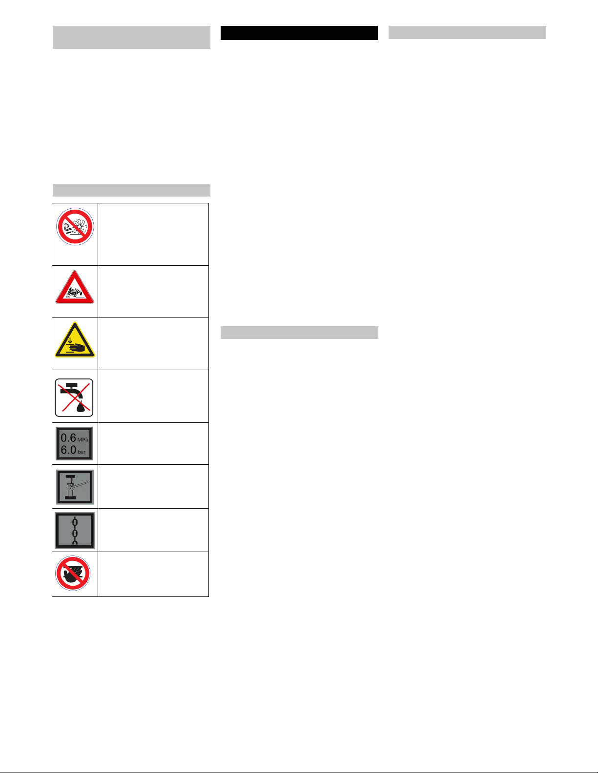
Symbols on the machine
� DANGER
Risk of fire!
Please do not sweep away
any burning substances such
as cigarettes, match sticks or
similar objects.
�
DANGER
Danger of tipping. Only empty
the waste container when the
appliance is placed on a level
and stable ground
� WARNING
Risk of being squeezed or
hurt at the belts, side-brush-
es, containers, machine cov-
er.
� CAUTION
Do not rinse out the dust filter.
Tyre pressure
Intake points for the jack
Lashing point
Risk of injury on account of
rotating roller brush. Open
the appliance hood only when
the engine has come to a halt.
Proper use
Foreseeable misuse
Suitable surfaces
27EN
-
3
– The machine with working equipment
must be checked to ensure that it is in
proper working order and is operating
safely prior to use. Otherwise, the appli-
ance must not be used.
– If the appliance is used in hazardous ar-
eas (e.g. filling stations) the corre-
sponding safety provisions must be ob-
served. It is not allowed to use the ap-
pliance in hazardous locations.
� DANGER
Risk of injury!
Do not use the appliance without an
overhead guard in areas where the op-
erator might get hit by falling objects.
– The operator must use the appliance
properly. The person must consider the
local conditions and must pay attention
to third parties, in particular children,
when working with the appliance.
– Prior to starting work, the operator must
ensure that all protective devices are
properly installed and function correct-
ly.
– The operator of the appliance is liable
for accidents with other individuals or
their property.
– Ensure that the operator wears tight-fit-
ting clothes. Wear sturdy shoes and
avoid wearing loose-fitting clothes.
– Check the immediate vicinity prior to
starting (e.g. children). Ensure suffi-
cient visibility!
– Never leave the device unattended as
long as it is switched on. The operator
may only leave the device when the key
(Intelligent Key) has been removed and
the device is secured against acciden-
tal movements.
– Please remove the key, when not in
use, to avoid unauthorised use of the
appliance.
– The appliance may only be used by per-
sons who have been instructed in han-
dling the appliance or have proven
qualification and expertise in operating
the appliance or have been explicitly
assigned the task of handling the appli-
ance.
– This machine is not intended for use by
persons (including children) with re-
duced physical, sensory or mental ca-
pabilities, or lack of experience and
knowledge.
– Children should be supervised to pre-
vent them from playing with the appli-
ance.
� Danger
Risk of injury!
Danger of tipping if gradient is too high.
– The falling and rising gradients in the di-
rection of travel may not exceed 12%.
Danger of tipping on unstable ground.
– Only use the machine on sound surfac-
es.
Danger of tipping with excessive sideways
tilt.
– The gradient perpendicular to the direc-
tion of travel should not exceed 10%.
The travel speed must be adapted to the
existing conditions.
�
DANGER
Risk of injury!
When working on the high emptying
system, completely lift and secure the
waste container.
NOTICE
The overhead guard (optional) protects the
driver against larger falling objects. Howev-
er, it does not provide rollover protection!
– Mind the weight of the appliance during
transport.
– Disconnect the battery and securely
fasten the device for transport.
– First switch off the device and remove
the KIK-key (Kärcher Intelligent Key)
before performing any cleaning or
maintenance tasks on the device, re-
placing parts or switching over to anoth-
er function.
– Always disconnect the battery when
working on the electrics.
– Do not clean the appliance with a water
hose or high-pressure water jet (danger
of short circuits or other damage).
– Maintenance work may only be carried
out by approved customer service out-
lets or experts in this field who are famil-
iar with the respective safety regula-
tions.
– Please observe the local safety regula-
tions regarding portable commercially
used appliances.
– Always use appropriate gloves while
working on the device.
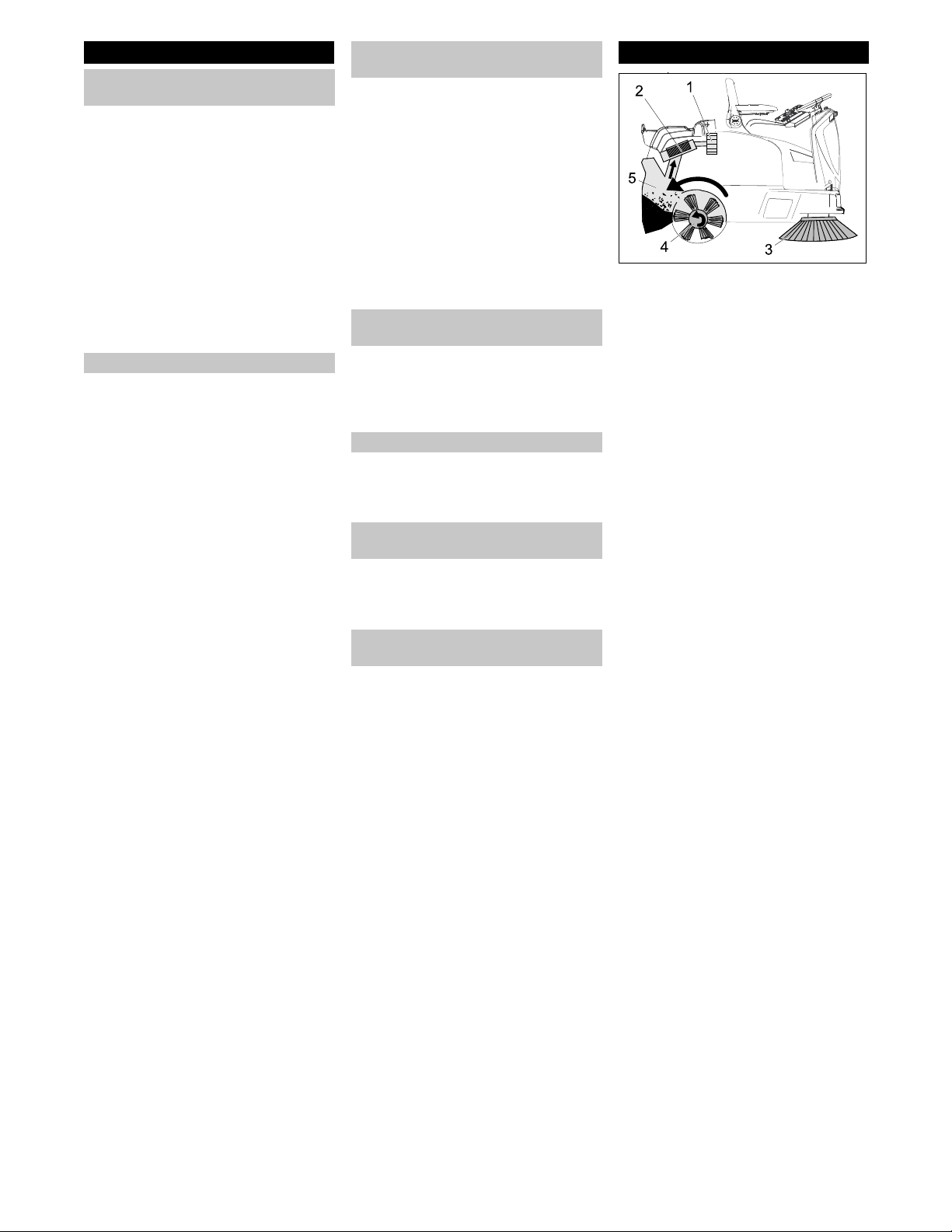
The sweeper operates using the overthrow
principle.
– The side brushes (3) clean the corners
and edges of the surface, moving dirt
and debris into the path of the roller
brush.
– The rotating roller brush (4) moves the
dirt and debris directly into the waste
container (5).
– The dust raised in the container is sep-
arated by the dust filter (2) and the fil-
tered clean air is drawn off by the suc-
tion fan (1).
– The cleaning of the dust filter (2) takes
place automatically.
Safety instructions
Safety instructions concerning the
operation
Operations
Safety information concerning the
driving operation
Appliances with high emptying
system
Devices with overhead guard
Safety information concerning the
transport of the appliance
Safety information concerning
maintenance and care
Function
28 EN
-
4
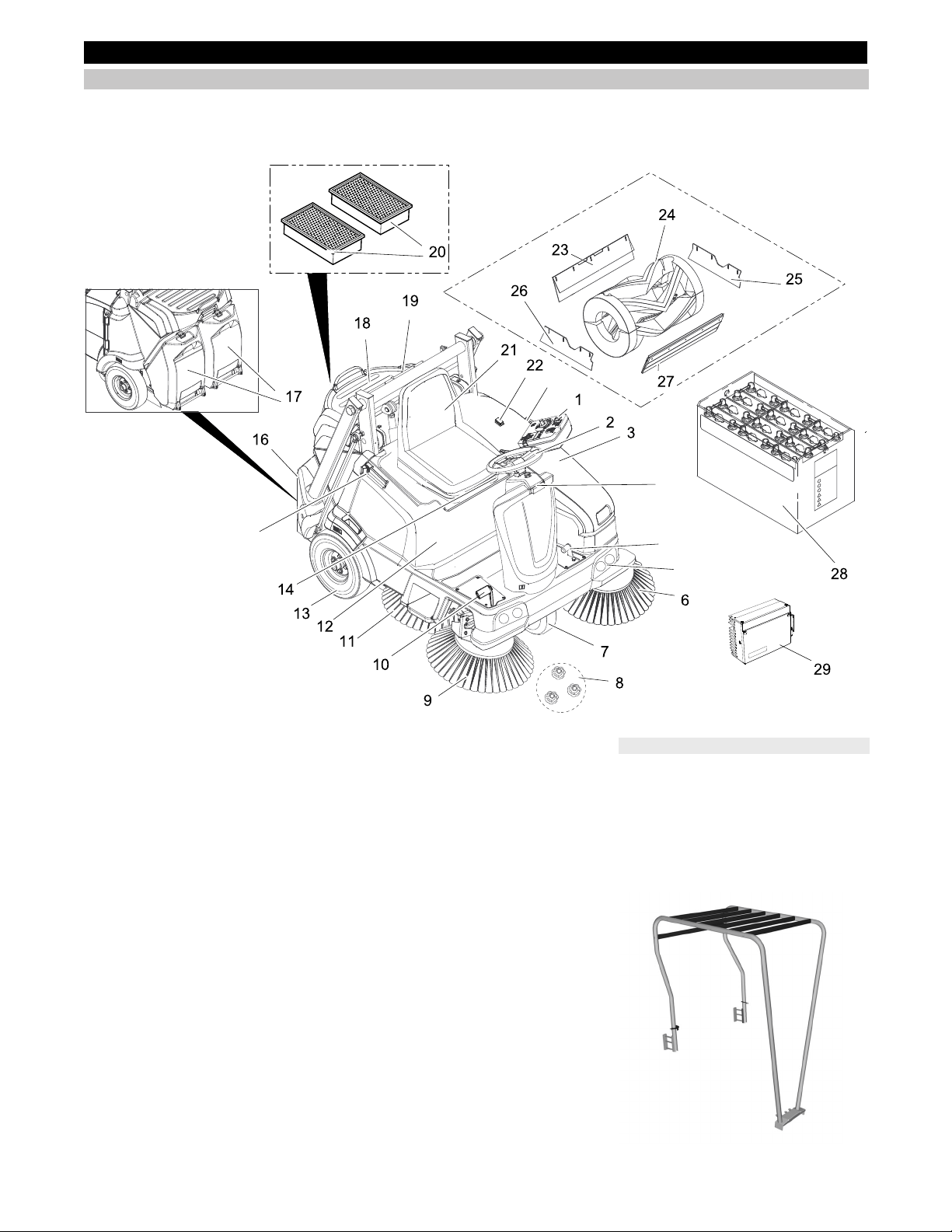
KM 105/100 R Bp
KM 105/100 R Bp Pack
KM 105/110 R Bp
KM 105/110 R Bp Pack
1 Operating field
2 Steering wheel
3 Cover on the left
4 Pedal for raising/lowering bulk waste
flap
5 Localised work illumination (option)
6 Left side brush (optional)
7 Driving operations
8 Fastener of the side brush
9 Right side brush
10 Drive pedal
11 Sickle brush (option)
12 Appliance cover right side
13 Rear wheel
14 Lever for seat adjustment
15 Holding rail for home base
16 Waste container high emptying system
KM 105/110 R Bp
KM 105/110 R Bp Pack
17 Waste container low emptying system
KM 105/100 R Bp
KM 105/100 R Bp Pack
18 Storage area
19 Storage cylinder support (safeguard
high emptying system)
20 Dust filter (flat-fold filter)
21 Driver seat (with seat contact switch)
22 Button for two-handed operation
KM 105/110 R Bp
KM 105/110 R Bp Pack
23 Rear sealing strip
24 Roller brush
25 Lateral sealing strip on the left
26 Lateral sealing strip on the right
27 Front sealing strip
28 Batteries
(KM 105/100(110) R Bp Pack: already
installed)
(KM 105/100(110) R Bp: not included in
delivery)
29 Charger
(KM 105/100(110) R Bp Pack: already
installed)
(KM 105/100(110) R Bp: not included in
delivery)
The following equipment that is installed
when ordering ex work or can be subse-
quently installed from Service is not dis-
played.
– Beacon lamp
– Comfort seat
– Fleet Management module
– Overhead guard
Operating and Functional Elements
Device view KM 105/100(110) R
4
5
15
15
15
Optional
29EN

-
5
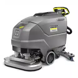
KM 125/130 R Bp
KM 125/130 R Bp Pack
1 Operating field
2 Steering wheel
3 Holding rail for home base
4 Cover on the left
5 Recessed grip
6 Pedal for raising/lowering bulk waste
flap
7 Localised work illumination (option)
8 Left side brush (optional)
9 Driving operations
10 Fastener of the side brush
11 Right side brush
12 Drive pedal
13 Sickle brush (option)
14 Rear wheel
15 Appliance cover right side
16 Lever for seat adjustment
17 Waste container high emptying system
18 Driver seat (with seat contact switch)
19 Dust filter (flat-fold filter)
20 Storage cylinder support (safeguard
high emptying system)
21 Beacon lamp (option)
22 Button for two-handed operation
23 Rear sealing strip
24 Roller brush
25 Lateral sealing strip on the left
26 Front sealing strip
27 Lateral sealing strip on the right
28 Batteries
(KM 125/130 R Bp Pack: already in-
stalled)
(KM 125/130 R Bp: not included in the
scope of delivery)
29 External charger
The following equipment that is installed
when ordering ex work or can be subse-
quently installed from Service is not dis-
played.
– Comfort seat
– Fleet Management module
– Overhead guard
Device view KM 125/130 R
Optional
30 EN
-
6
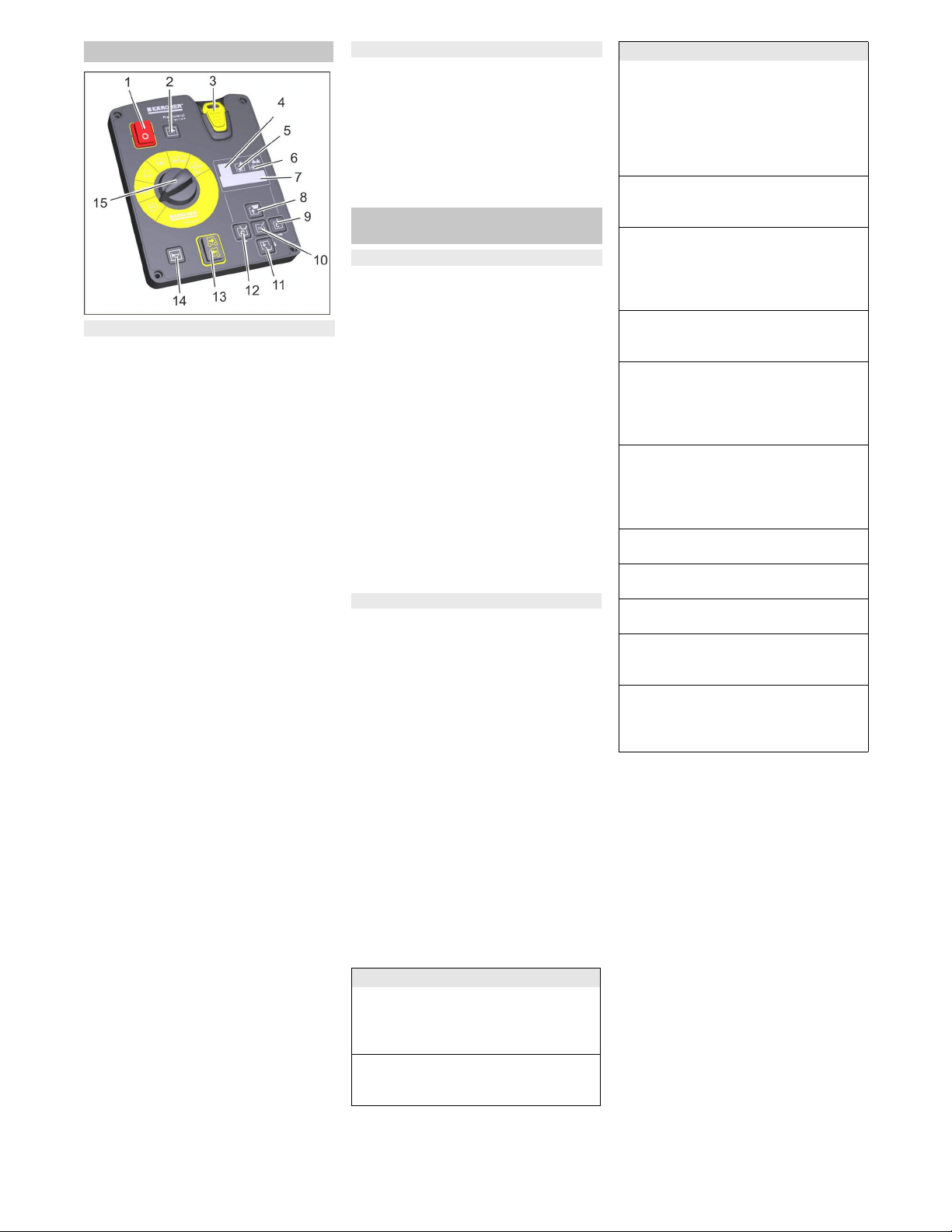
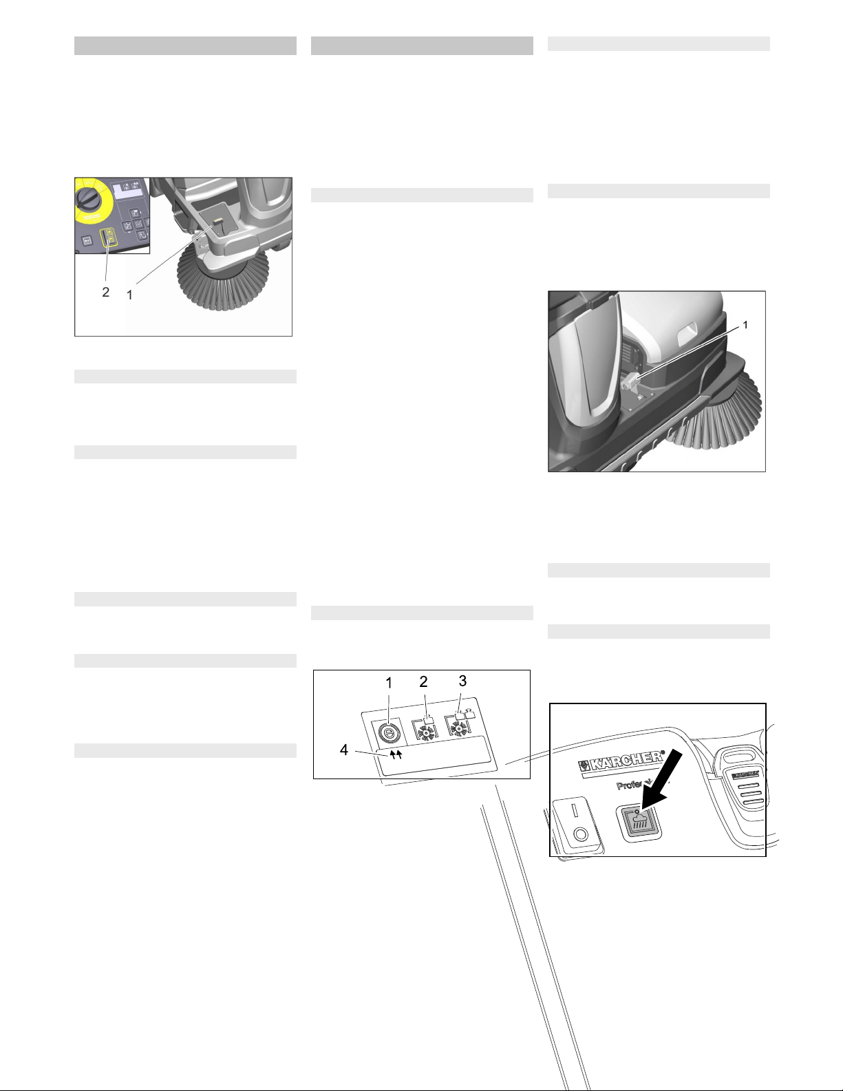
1 Main switch
Position 0: Appliance is decommis-
sioned
Position I: The appliance is ready for
operation.
2 Button suction blower with indicator
lamp
Lamp is illuminated: Suction blower
and filter dedusting deactivated:
– for sweeping damp or wet floors, or fi-
brous dry waste such as straw, hay, etc.
Lamp off: Suction blower and filter de-
dusting activated (default):
– for sweeping dry floors
3 KIK-key (Kärcher Intelligent Key)
yellow - operator
grey - supervisor
4 Display sweeping programme "ECO"
– for even floors with minor soiling
Note: This sweeping programme is ac-
tivated by default with every start-up of
the sweeping system, even if another
sweeping programme was selected be-
fore.
Note: The selected sweeping pro-
gramme is shown on the display, the
setting is effected by means of the di-
rection keys.
5 Display sweeping programme "MEDI-
UM"
– for normally soiled floors
6 Display sweeping programme
"HEAVY"
– for heavily soiled and uneven floors
7 Display
8 Lift waste container (high emptying sys-
tem) and direction key "upwards"
9 Tip out waste container (high emptying
system) and direction key "to the right"
10 Confirmation key "OK"
11 Lower waste container (high emptying
system) and direction key "down"
12 Swivel in waste container (high empty-
ing system) and direction key "to the
left"
13 Selector for the direction of travel
14 Horn
15 Program selection switch
The default language on the display is Eng-
lish.
Select the desired language on the control
panel prior to working with the machine.
How the language is set for the yellow and
grey key (Intelligent Key) is shown in the il-
lustrated brief instructions on Page 2 of
these operating instructions or in the follow-
ing Chapter "Intelligent Key yellow/grey".
The parameters for the various cleaning
programmes are preset. The indication
takes place on the display.
The texts on the display are plain texts and
therefore self-explanatory. The selection of
the desired sweeping program is made by
means of the direction key "to the right".
Shown display texts are:
>Battery charge indicator<
>Operating hours and sweeping pro-
gramme<
>Usability of the roller brush: .. %<
>Day counter .. h .. min<
Extra with upgrade kits:
>Switch on beacon light<
>Switch on working light<
If you wish to permanently change the pa-
rameters, you must use a grey KIK-key to
make the settings. The procedure is de-
scribed in section "Grey KIK-key".
With the grey KIK-key the authorisations for
the yellow KIK-key are enabled.
Parameters that are adjusted with the grey
KIK-key are kept until another setting is se-
lected.
Insert the grey KIK-key.
Turn the programme selector switch to
"ON".
Push the direction key "upwards" or
"downwards" until the >key manager<
menu appears.
Note: In this menu item the authorisa-
tions for the yellow KIK-key are ena-
bled.
Confirm the message with the "OK"
key.
Remove the grey KIK-key and within
the seconds being counted down insert
the yellow KIK-key that is to be person-
alised.
Push the direction keys "upwards" or
"downwards" and select menu items.
To transfer the settings to the yellow
KIK-key:
While the seconds are counted down,
select >YES< with the direction key "to
the right" and confirm with the "OK" key.
Note: Thereby the settings made are
transferred to the yellow KIK-key and
are enabled.
Operating field
Control elements on the control panel
Language setting on the control panel
KIK-key (Kärcher Intelligent Key)
yellow/grey
Yellow KIK-key
Grey KIK-key
Available menu items are:
>Language selection<
18 languages are available in the language
selection, among others German, English,
French, Spanish, Greek and Russian.
>Device operation locked/enabled<
The yellow KIK-key can be locked for the
operation of this machine here.
>Sweeping track locked/enabled<
With a locked sweeping track the sweeping
programme ECO, MEDIUM or HEAVY is to
be set and cannot be changed by the oper-
ator. With an enabled sweeping track you
can change between the 3 sweeping pro-
grammes during operation.
>Dust level locked/enabled<
Adaption of the automatic filter cleaning
(TACT) to the environment.
>Light on/off<
The operator can switch on/off the light
(optional).
Note: The light turns on automatically
when the device is started.
>Light locked/enabled<
Continuous operation with light is activated
or locked.
>Flashing beacon locked/enabled<
The operator can choose whether he or
she wants to drive with or without the flash-
ing beacon; when starting the device, the
flashing beacon is on automatically.
>Flashing beacon mode locked/ena-
bled<
It can be selected whether the flashing
beacon is necessarily on (even if it has
been switched off by the operator) or not.
>Speed locked/enabled<
Without function
>Sweeping speed locked/enabled<
Without function
>Blower/pump locked/enabled<
Without function
>Enable delete day counter<
It can be selected whether the operator is
able to reset the day counter.
>Programming yes/no<
As the last menu item the >Program-
ming< display with the seconds counted
down appears.
Available menu items are:
31EN
-
7
Make sure that there is no more than 1
KIK-key near the control panel.
If this should be the case, the fault F/11
may appear on the display.
Note
The functions are only activated when the
main switch is switched on and the KIK-key
is inserted.
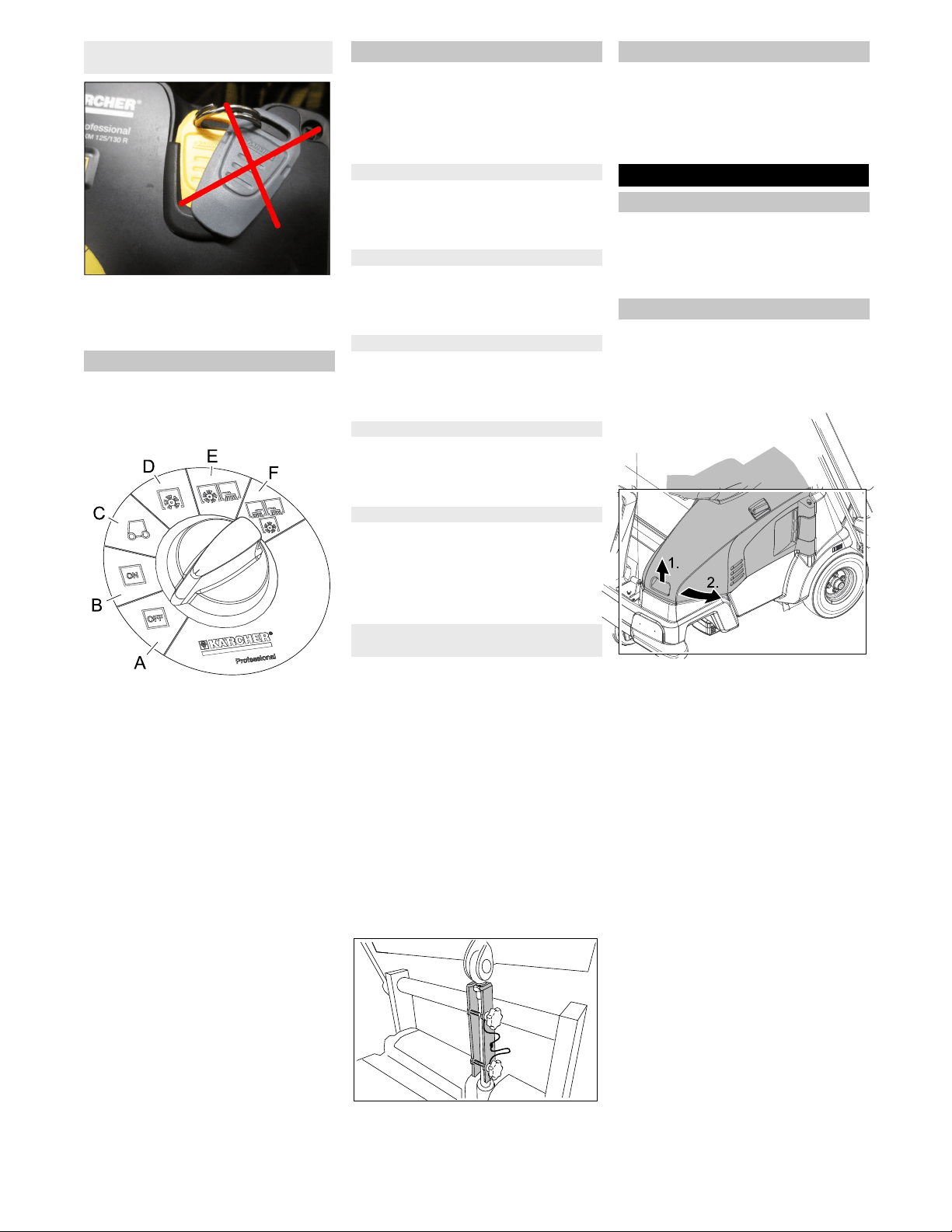
A OFF
Device is switched off
B ON
The appliance is now ready for opera-
tion.
C Drive the machine
Drive to the operating location; in order
to do so, push the accelerator pedal.
Note
Roller brush and side brushes are
raised and switched off.
D Sweeping with sweep roller
Roller brush is lowered.
E Sweeping with roller brush and right
side brush
Roller brush and right side brush are
lowered, the sickle brush (optional) is
ready for operation.
F Sweeping with roller brush and right
and left side brush
Roller brush, right side brush and left
side brush (optional) are lowered, the
sickle brush (optional) is activated.
� WARNING
This appliance is equipped with a variety of
safety installations. The proper function of
every safety installation must be checked
prior to operation and must NOT be over-
ridden!
The main switch serves the immediate
shutdown of the electrical drives in case of
emergencies and may only be used for this
purpose.
The left cover is equipped with a safety in-
stallation that switches off the running de-
vice when it is opened and issues a warn-
ing message on the display.
Both waste containers are equipped with a
safety installation that switches off the run-
ning device when it is opened and issues a
warning message on the display.
The high emptying system is equipped with
a safety installation that blocks the sweep-
ing operation during the emptying proce-
dure.
Appliances with a high emptying system
are equipped with a button for two-hand op-
eration.
For emptying the waste container, the
button must be pressed together with
the keys of the high emptying system.
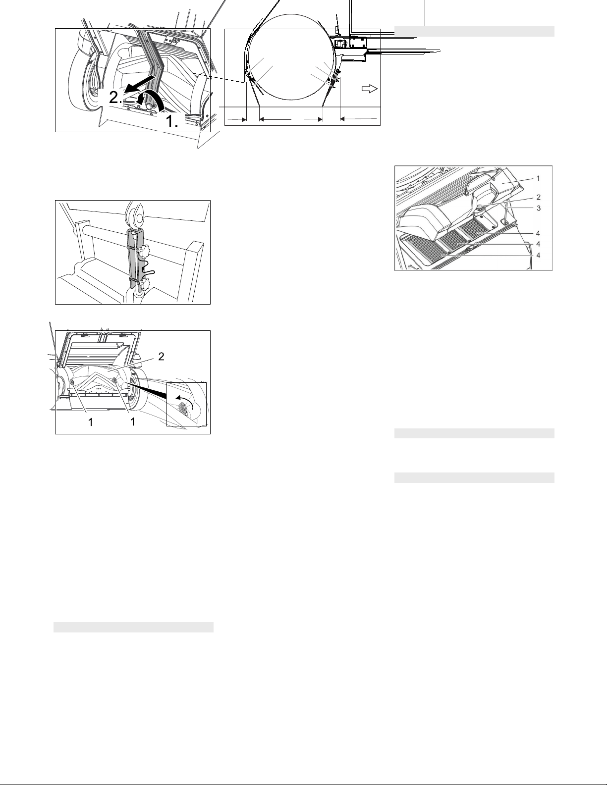
The safety support is attached to the cross-
beam by means of 2 star screws for stor-
age.
�
CAUTION
Risk of injury!
During any work underneath the lifted
waste container, the lifting cylinder
must be secured by means of a safety
support.
Perform the safeguarding only from
outside the hazard zone.
Remove safety support, in order to do
this, unscrew 2 star screws.
Insert safety support into the piston rod
for the lifting cylinder and secure it.
Note: The round notch must point up-
wards.
The appliance is equipped with an auto-
matic parking brake that is integrated in the
front-wheel drive.
The parking brake takes effect as soon as
the device comes to a standstill and the ac-
celerator pedal is released.
The cover with the seat can be removed
for repair or maintenance work.
Prior to removing the cover, disconnet
the electrical socket plug connection of
the seat contact switch.
ATTENTION
The left cover may only be opened when
the programme selector switch is in the
"OFF" position and the key (Intelligent Key)
is removed.
Opening the left cover during operation of
the device is prohibited.
Grab the front of the cover on the re-
cessed grip, unlock it towards the top
and swivel it to the side.
Illustration is symbolic, here KM 105/...
Note: The cover is equipped with a safety
installation that switches off the drive when
it is opened and issues a warning message
on the display. If the cover is not properly
closed the device will not operate.
If a warning message is pending, it can be
reset as follows:
Completely close the bonnet (locking in
place).
Turn the programme selector switch to
"ON".
Sit on the driver seat.
Notes on operation using the KIK-key
(Kärcher Intelligent Key)
Program selection switch
Safety Devices
Main switch
Cover on the left
Waste container (low emptying system)
Waste container (high emptying system)
Button for two-hand operation
Safety support waste container (high
emptying system)
Parking brake
Before Startup
Remove the appliance cover
Opening/closing cover on the left
32 EN
-
8
� DANGER
Risk of personal injury or damage!
Observe the weight of the appliance
when you load it!
Do not use a forklift truck to unload the
machine as this may damage it.
ATTENTION
Charge the battery before commissioning
the machine.
When loading the appliance a suitable
ramp must be used!
If the machine is delivered on a pallet,
you must create an unloading ramp us-
ing the boards provided.
To unload the machine, proceed as follows:
Cut plastic packing belt and remove foil.
Remove the elastic tape fasteners at
the stop points.
Connect battery (see section on Care
and maintenance)
Four indicated floor boards of the pallet
are fastened with screws. Unscrew
these boards.
Place the boards on the edge of the pal-
let. Place the boards in such a way that
they lie in front of the four wheels of the
machine. Fasten the boards with
screws.
Illustration is symbolic, here KM 105/...
Slide the four support beams included
in the packaging under the ramp.
Remove the wooden blocks for locking
the wheels.
� DANGER
Risk of accident, risk of injury!
It is prohibited to release the emergen-
cy brake on an incline without using the
stopper.
Before releasing the immobilizing
brake, the machine must be secured to
prevent it rolling away. If the device is
not secured, it will roll with a speed of
approx. 4.5 km/h after releasing the
parking brake until the electronics
brakes the device.
Release emergency brake:
Illustration is symbolic, here KM 105/...
Remove the brake level from the wheel
and put it in its position.
The immobilizing brake is thus deacti-
vated; the machine can now be moved.
Slide the machine over the prepared
ramp from the pallet.
Connect the battery, refer to Chapter
"Connecting and installing the battery".
Insert KIK-key and main switch to posi-
tion 1/ON.
Turn the programme selector switch to
position C (drive).
Press the drive direction switch and
slowly move the machine down from
the ramp.
Turn the programme selector switch to
position A (OFF).
Upon delivery the side brush is not in-
stalled, install side brush prior to commis-
sioning.
Refer to Chapter "Care and mainte-
nance/replacing the side brush".
ATTENTION
Using non-rechargeable batteries is prohib-
ited.
Only use batteries and chargers approved
by the manufacturer.
Replace batteries with the same battery
type only.
Prior to disposal of the vehicle, the batter-
ies must be removed and disposed of in ac-
cordance with local regulations.
Follow accident prevention regulations as
well as DIN VDE 0510, VDE 0105 T.1.
Please observe the following warning notes
when handling batteries:
�
DANGER
Risk of fire and explosion!
Do not place tools or similar items on
the battery. Risk of short-circuit and ex-
plosion.
Smoking and open flames must be
strictly avoided.
Rooms where batteries are charged
must have good ventilation because
highly explosive gas is emitted during
charging.
Danger of causticization!
Use caution with leaking batteries (sul-
phuric acid may leak).
Risk of injury!
Ensure that wounds never come into
contact with lead. Always clean your
hands after working on batteries.
Unloading tips
Net weight (transport weight)
Weight (without driver, without attachment
kits, without batteries)
KM 105/100 R (low emptying sys-
tem)
KM 105/110 R (high emptying
system)
KM 125/130 R (high emptying
system)
305 kg
405 kg
500 kg
Weight (without driver, without attachment
kits, with batteries)
KM 105/100 R (low emptying sys-
tem)
KM 105/110 R (high emptying
system)
KM 125/130 R (high emptying
system)
490 kg
590 kg
820 kg
* If upgrade kits are installed, the weight is
respectively higher.
Push the sweeper off the pallet
(appliance without built-in battery)
Drive the sweeper off the pallet
(appliance with built-in battery)
Install side brush
Notes regarding the battery
Safety notes regarding the batteries
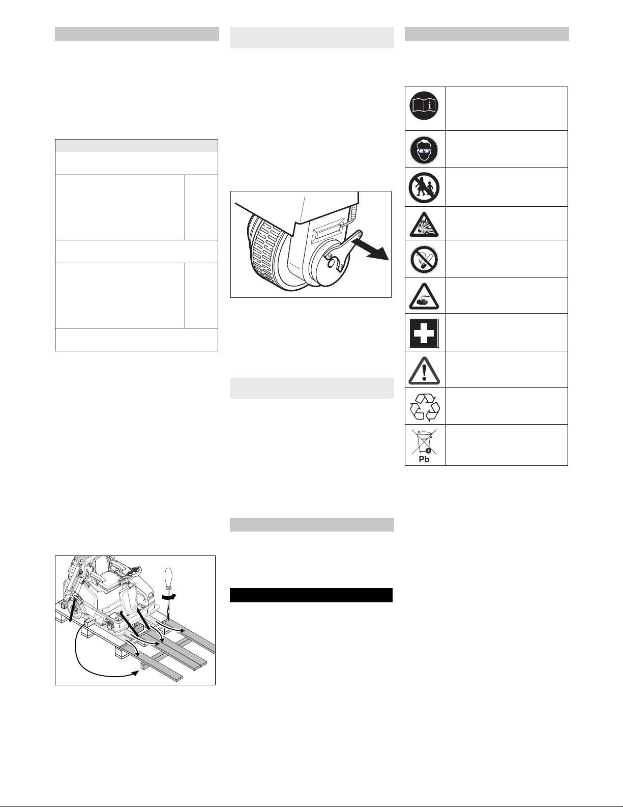
Observe the directions on the
battery, in the instructions for
use and in the vehicle operating
instructions!
Wear an eye shield!
Keep away children from acid
and batteries!
Risk of explosion!
Fire, sparks, open light, and
smoking not allowed!
Danger of causticization!
First aid!
Warning note!
Disposal!
Do not throw the battery in the
dustbin!
33EN

-
9
When used normally, and when observing
the instructions, lead-acid batteries do not
pose any risk.
However, keep in mind that lead-acid bat-
teries contain sulphuric acid which can
cause chemical burns and corrosion.
If there is spillage or, if the battery is
leaking, acid is escaping, lay down a
binding agent such as sand. Do not let
it reach the sewer system, soil or a body
of water.
Neutralise the acid with lime/baking
soda and dispose of it according to local
regulations.
Contact a waste management compa-
ny to dispose of faulty batteries.
Rinse thoroughly with lots of clear water
if acid gets into the eye or comes in con-
tact with the skin.
Then consult a doctor immediately.
Wash off the acid If it comes in contact
with the clothes.
Change clothing.
�
Warning
Regularly check the fluid level in acid-filled
batteries.
– The acid in a fully charged battery has a
specific weight of 1.28 kg/l at a temper-
ature of 20 °C.
– The acid in a partially discharged bat-
tery has a specific weight between 1.00
and 1.28 kg/l.
– The specific weight of the acid must be
uniform in all cells.
Unscrew all cell caps.
Take a sample from each cell using the
acid tester.
Put the acid sample back into the same
cell.
Where fluid level is too low, top up cells
to the mark provided with distilled wa-
ter.
Charge battery.
Screw in cell caps.
We recommend the use of our batteries
and chargers; only then a claim under war-
ranty exists.
NOTICE
With the KM 105/100 R Bp Pack, the KM
105/110 R Bp Pack and the KM 125/130 R
Bp Pack low-maintenance batteries and
the charger are already installed.
ATTENTION
Only if you use the batteries and chargers
recommended by Kärcher, a claim under
warranty exists.
KM 105/100 R / KM 105/ 110 R Bp .
125/130 R Bp
Note
When using batteries of other manufactur-
ers, the maximum battery dimensions must
be observed.
KM 105/100 R Bp
KM 105/110 R Bp
The device requires 4 single batteries with
6 volt each or a battery trough.
The available space (LxWxH) in the device
is: 622 mm x 402 mm x 379 mm
KM 125/130 R Bp
The available space (LxWxH) in the device
is:827 mm x 324 mm x 462 mm
Please follow these instructions if you are
using low-maintenance batteries:
– It is necessary to conform to the maxi-
mum battery dimensions.
– When charging low-maintenance bat-
teries, the left cover must be opened.
– While charging maintenance-free bat-
teries, follow the specifications of the
battery manufacturer.
Open left cover.
Remove the appliance cover.
Insert batteries into the battery mount.
� Warning
Pay attention to correct poles.
Connect pole terminal (red cable) to
positive pole (+).
Screw the connection lines onto the
batteries.
Connect pole terminal to negative pole
(-).
NOTICE
When removing the battery, make sure that
the negative pole lead is disconnected first.
Check that the battery pole and pole termi-
nals are adequately protected with pole
grease.
NOTICE
Charge the batteries before commissioning
the appliance.
� DANGER
Risk of injury!
Comply with safety regulations on the
handling of batteries. Observe the di-
rections provided by the manufacturer
of the charger.
�
DANGER
Risk of injury!
Only put the charger into operation if
the mains connection is free of damage.
A damaged mains connection must im-
mediately be replaced by the manufac-
turer, the customer service or a quali-
fied person.
� DANGER
Risk of injury!
Charge the battery only with an appro-
priate charger.
NOTICE
The charger is controlled electronically and
completes the charging process automati-
cally. All functions of the device are auto-
matically interrupted during the charging
process.
NOTICE
Procedures in the event of unintentional
release of battery acid
Check and correct the fluid level of
the battery (only for low-
maintenance batteries)
Recommended batteries, chargers
Order No.
Volume [m
3
} *
Air flow [m
3
/h] **
400 Ah - Trogbat-
terie
6.654-
156.0
33,0 13,20
240 Ah - Trogbat-
terie
6.654-
112.0
19,8 07,92
240 Ah - Einzelbat-
terie 6V
6.654-
119.0
5,12 2,05
180 Ah - Einzelbat-
terie 6V
6.654-
124.0
3,8 1,52
* Minimum volume of the battery charging
room
** Minimum air flow between the battery
charging room and the surroundings
Use of batteries and chargers of other
manufacturers
Battery Battery set Charger
240 Ah - Trog-
batterie (nass)
6.654-112.0 4.654-003.0
180 Ah - Einzel-
batterie (Gel)
6.654-124.0 4.654-022.0
240 Ah - Einzel-
batterie (Gel)
6.654-119.0 4.654-023.0
Battery Battery set Charger
400 Ah - Trog-
batterie (nass)
6.654-156.0 6.654-327.0
240 Ah - Trog-
batterie (nass)
6.654-112.0 6.654-325.0
240 Ah - Einzel-
batterie (Gel)
6.654-119.0 6.654-326.0
Maximum battery dimensions (single
battery)
Installing and connecting the
batteries
Charging battery
34 EN
-
10
When the batteries are charged, first re-
move the charger from the mains and then
disconnect it from the batteries.
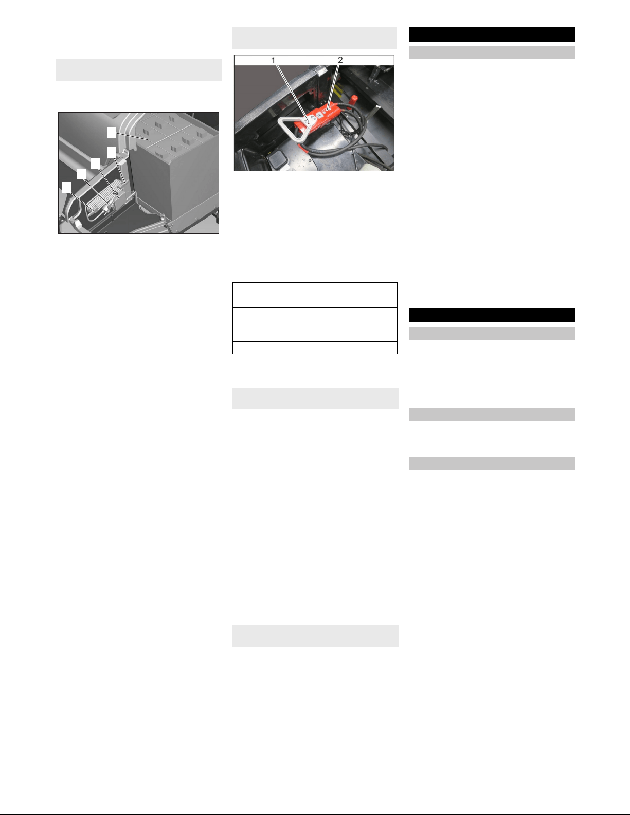
With the KM 105/100(110) R Bp Pack the
low-maintenance batteries and the charger
are already installed.
1 Retainers for mains connection (fold-
ing)
2 Mains cable with mains plug
3 Connection for mains connection of the
charger
4 Batteries
Open left cover.
Fold in retainers and remove mains
connection.
Insert the plug of the charger into the
socket.
Note
The progress of the charging process is
shown via a bargraph (5 bars) on the dis-
play.
At the beginning of the charging process
5 lines can be seen briefly.
Little by little the 5 bars are filled (depend-
ing on the charging state of the battery at
the beginning of the charging process,
more slowly or faster). When the last bar is
filled, the battery is charged.
After charging
Unplug the charger from the mains.
Store the mains connection away in the
retainer and clip in the mains plug.
1 Battery socket
2 Working connection
Open left cover.
Unplug the battery plug and replug it in
the charger connection
Insert the mains plug of the charger into
the socket. The charging process will
start.
The progress of the charging process is
displayed on the charger.
After charging
Replug the battery plug into the working
connection
Add distilled water after the charging
process has been completed; observe
the correct acid level. There are corre-
sponding indicators on the battery.
�
DANGER
Danger of causticization!
Adding water to the battery in its dis-
charged state can cause the acid to
leak.
Wear protective glasses and protective
clothing when handling battery acid.
Observe the regulations concerning the
handling of batteries!
� WARNING
Risk of damage!
Use only distilled or desalinated water
(EN 50272-T3) for filling the battery.
Do not add any substances (so-called
performance improving agents), else
warranty claims will not be entertained.
Rinse thoroughly with lots of clear water
if acid gets into the eye or comes in con-
tact with the skin.
Then consult a doctor immediately.
Change clothing.
Wash off the acid If it comes in contact
with the clothes.
To be performed by the operator on a
daily basis!
The description of the checks and work be-
low can be found in Chapter "Care and
maintenance/maintenance work".
Check safety function of the left cover
(device must not start while the cover is
open).
Check function of seat contact switch.
Check the roller brush and the side
brush for wear, foreign bodies and
wrapped belts
During a standstill of the machine:
Check the drive pedal for ease of move-
ment in order to guarantee functional
reliability or timely detect a jamming of
the pedal.
Empty waste container.
Check tyre pressure.
Check battery acid level.
With appliances with high emptying
system: Check filling level at the hy-
draulic unit.
Pull seat adjustment lever inwards.
Slide seat, release lever and lock in
place.
Check that the seat is properly locked in
position by attempting to move it back-
wards and forwards.
Note: The max. load of the storage area is
20 kg.
Ensure safe fastening of the cargo.
Preconditions for the functioning operation
of the appliance are:
– The KIK-key (grey or yellow) with the
authorisation for the operation of the
device must be inserted in the key slot
of the control panel.
– The main switch must be in position 1.
– The programme selector switch may
not be in the "OFF" position.
– Waste container and left cover must be
closed and locked in place.
– Sit on the driver seat, the seat contact
switch is activated.
Charging process KM 105/100(110) R Bp
Pack
1
2
3
1
4
Charging process for devices with
external charger
orange Battery is being charged
green Battery is charged
red Battery is not connected,
deep discharged or de-
fective.
blinks red Battery defective
Information with low-maintenance
batteries
Information concerning accidents with a
risk of chemical burns
Start up
Prior to start/safety test
Operation
Adjusting driver's seat
Storage area
Starting up the appliance
35EN
-
11
� CAUTION
Risk of damage!
Always press the accelerator pedal
carefully and slowly. Do not jerkily
change from reverse to forward drive or
vice versa.
The travel speed must be adapted to
the existing conditions.
1 Drive pedal
2 Driving direction switch
Set the travel direction to forward using
the travel direction switch at the control
panel.
Press accelerator pedal down slowly.
�
DANGER
Risk of injury!
When reversing, there must not be any
risk for third parties, have somebody
marshal the driver if necessary.
Set the travel direction to reverse using
the travel direction switch at the control
panel.
Press accelerator pedal down slowly.
The accelerator pedal can be used to
vary the driving speed infinitely.
Avoid operating the pedal fitfully.
Release the accelerator pedal, the ma-
chine brakes automatically and stops.
Note: Should the device not come to a
stop, push the main switch to the "0" po-
sition for an "Emergency stop".
ATTENTION
Objects or loose obstacles may not be run
over or pushed.
Stationary obstacles of a height of up to
6 cm can be slowly and carefully driven
over (only when the coarse dirt flap is
opened).
Drive over stationary obstacles higher
than 6 cm (2
1/3
inch) only when using a
suitable ramp.
� DANGER
Risk of injury! If the bulk waste flap is open,
stones or gravel may be flung forwards by
the roller brush. Make sure that this does
not endanger persons, animals or objects.
CAUTION
Do not sweep up packing strips, wire or
similar objects as this may damage the
sweeping mechanism.
– Adjust the driving speed to the condi-
tions in order to achieve an optimal
cleaning result.
– Empty the waste container at regular in-
tervals during the sweeping operation.
Note: If mainly gravel was swept up
(high weight of the waste), empty the
waste container sooner.
With appliances with low emptying
system: There is a marking for the
maximum filling level for gravel on the
waste container. The marking becomes
visible when the waste container is re-
moved.
– Lower the roller brush while cleaning
surfaces.
– Preferably perform the cleaning of side
edges with the right side brush.
Information on the sickle brush (option-
al)
– The sickle brush (optional) is only low-
ered during left cornering.
– The sickle brush lowers during the
sweeping operation with the side brush
when the "OK" button is pressed.
– The sickle brush has an after-running
time upon switching off the sweeping
operation.
For cleaning with the roller brush 3 different
sweeping programmes are available, they
are shown by 2 arrows on the display.
1 Sweeping programme "ECO"
2 Sweeping programme "MEDIUM"
3 Sweeping programme "HEAVY"
4 Indicator (2 arrows)
Note: By default the sweeping programme
"ECO" is activated during start-up.
If another sweeping programme is re-
quired, proceed as follows (a precondition
is that a KIK-key with the enabled authori-
sation is inserted in the control panel).
(Programme selector switch in position D,
E, F)
Stop the machine.
Push the direction key "to the right" in
order to select the desired sweeping
programme.
Note: The indicator (2 arrows) on the
display points to the selected sweeping
programme.
Note: To sweep up larger items up to a
height of 50 mm, e.g. cigarette packs, the
bulk waste flap must be raised briefly.
Raising bulk waste flap:
Push the coarse dirt flap pedal towards
the front and hold it there briefly.
Illustration is symbolic, here KM 125/130 R
1 Pedal of bulk waste flap
To lower it, take foot off pedal.
Note: An optimum cleaning result can
only be achieved if the bulk waste flap
has been lowered completely.
Turn the programme selector switch to
the E or F position. The side brushes
and roller brush are lowered.
To protect the filter from moisture:
Switch the suction blower off using the
button on the control panel.
Note: The indicator lamp is illuminated.
Drive the machine
Drive forward
Reverse drive
Driving method
Brakes
Driving over obstacles
Sweeping mode
Information on the sweeping operation
Sweeping with sweep roller
Selecting a sweeping programme
Sweeping with bulk waste flap raised
Sweeping with side brushes
Sweeping damp or wet floors
36 EN
-
12
To avoid clogging of the filter system:
Switch the suction blower off using the
button on the control panel.
Work with suction blower switched on.
Note: The suction blower is activated
by default when switching on a sweep-
ing programme.
The appliance is equipped with an auto-
matic filter cleaning system.
The cleaning takes place automatically ap-
prox. every 15 seconds. In the process a
short blow-off sound can be heard.
Check the installed dust filter for con-
tamination every once in a while. Re-
place a heavily contaminated or defec-
tive filter.
Note: After parking the appliance, wait at
least 1 minute before opening or emptying
the waste container. This way the dust can
settle.
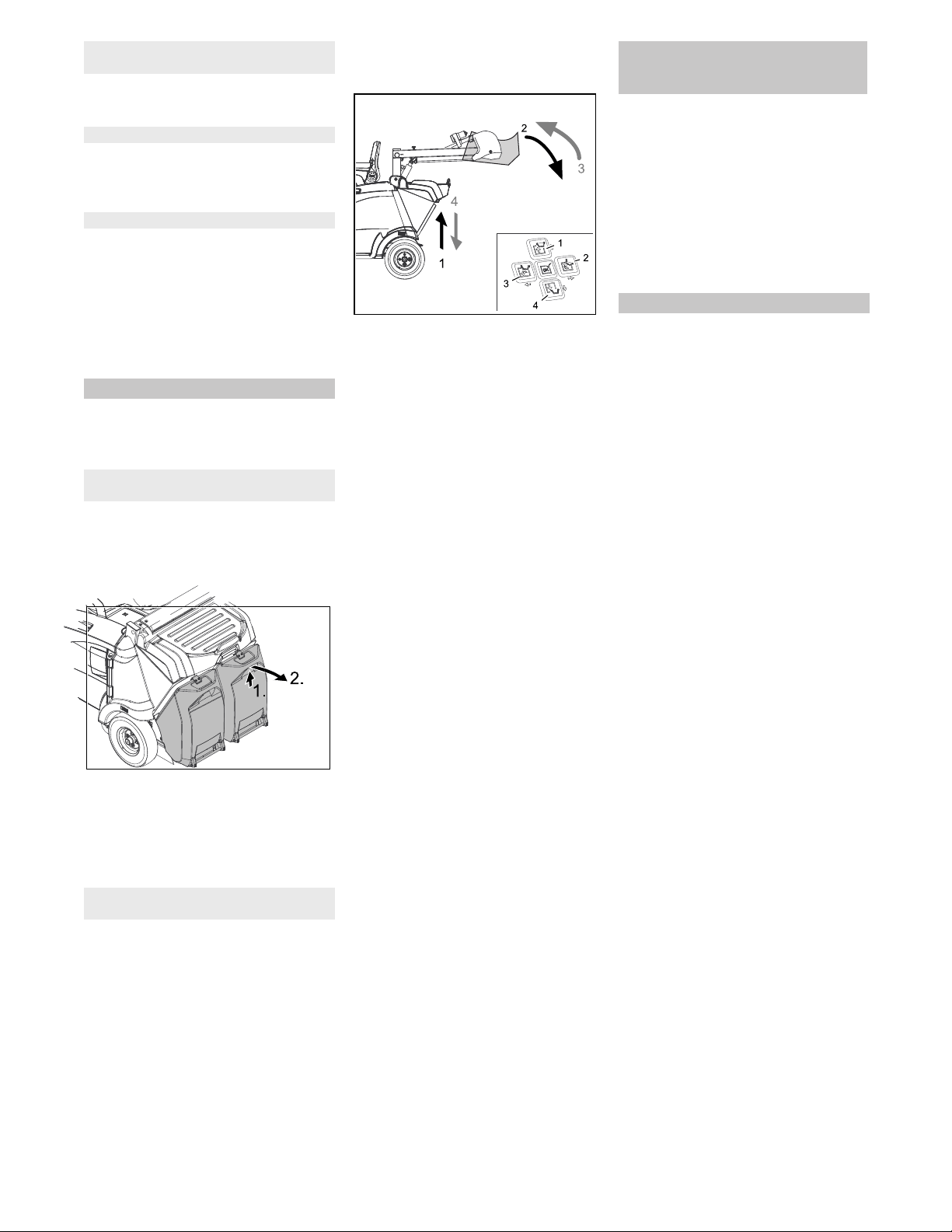
Park the sweeper on an even surface.
Turn the program selection switch to
"OFF".
Slightly lift the waste container and
swivel it downwards to the rear, then
unhinge the waste container.
Empty waste container.
Slide the waste container in and lock it
in place, check for proper seating of the
waste container
Caution
Risk of crushing hands!
Empty the second waste container.
The high emptying system of the appliance
allows the direct disposal of the waste in
the waste container into a refuse container
(for maximum unloading height see Chap-
ter "Technical data").
� Danger
Risk of injury! When emptying the waste
container, care should be taken to ensure
that no persons or animals are within its
swivelling range.
� Danger
Danger of crushing. Never reach into the
rod assembly for the drainage mechanism.
Stay away from the area under the raised
container.
�
Danger
Danger of tipping. Place the machine on an
even surface during emptying.
Turn the programme selector switch to
position C (drive).
Roughly position the appliance.
NOTICE
The container can only be tilted and emp-
tied once a set minimum level has been
reached.
NOTICE
The following steps can only be performed
in the two-hand operation. Push the two-
hand operation button on the left cover to-
gether with the corresponding direction
keys 1 to 4 on the control panel.
Raise waste container: Push the two-
hand operation button and direction key
1.
Note: Function reacts with a delay.
�
CAUTION
Do not switch into the sweeping mode
(programme selector switch in D, E, F posi-
tion) while the waste container is raised.
Slowly drive towards the collection con-
tainer.
Tipping the waste container outwards:
Push the two-hand operation button
and direction key 2.
Note: Function reacts with a delay.
Completely tip the waste container in-
wards: Push the two-hand operation
button and direction key 3.
Note: Function reacts with a delay.
Drive away the collection container
slowly.
Lower the waste container to the end-
position: Push the two-hand operation
button and direction key 4.
Note: Function reacts with a delay.
Note: The waste container can only be
completely lowered after it has been
tipped inwards into its initial position.
If the message >Charge battery!< ap-
pears on the display during cleaning
work, the machine can only be driven
for approx. 15 more minutes to protect
the battery against total discharge.
It is highly recommended to drive to the
charging station and to charge the bat-
tery.
If this message is ignored, the message
>BAT switch off!< will eventually ap-
pear on the display. Driving the ma-
chine is no longer possible now.
Note: After switching off the appliance, the
dust filter is automatically dedusted.
Park the sweeper on an even surface.
Turn the program selection switch to
"OFF".
Remove KIK-key.
Sweep in fibrous and dry waste (such as
dry grass, hay)
Sweeping dry floors
Filter dedusting
Emptying waste container
With appliances with low emptying
system
With appliances with high emptying
system
Display message >Charge battery!<
(KM 105/... R Bp and KM 105/...R Bp
Pack)
Turn off the appliance
37EN
-
13
� DANGER
Risk of personal injury or damage!
Mind the weight of the appliance during
transport.
�
DANGER
Risk of accident, risk of injury!
When loading the device, the drive and
the parking brake must be operational.
The appliance must always be moved
up or down slopes by engaging self-
propulsion.
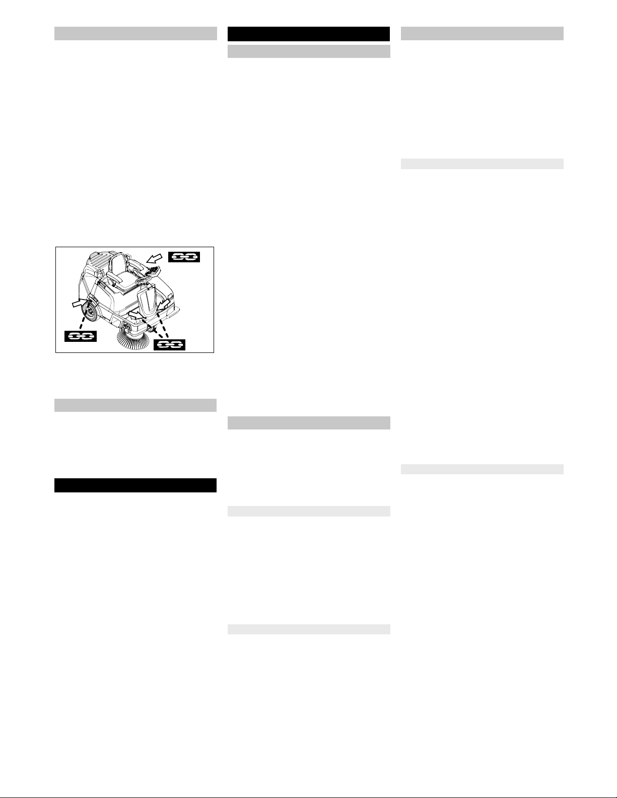
Secure the wheels of the machine with
wheel chocks.
Secure the machine with tensioning
straps or cables.
Note: Observe markings for fixing
points on the base frame (chain sym-
bols). Only unload the appliance on lev-
el grounds.
Illustration is symbolic, here KM 105/...
When transporting in vehicles, secure
the appliance according to the guide-
lines from slipping and tipping over.
� CAUTION
Risk of personal injury or damage!
Consider the weight of the appliance
when storing it.
Park the machine in a safe and dry
place.
If the sweeper is going to be out of service
for a longer time period, observe the follow-
ing points:
Park the machine on an even surface.
Clean the inside and outside of the
sweeper.
Park the machine in a safe and dry
place.
Turn the program selection switch to
"OFF".
Remove KIK-key.
Main switch to position 0.
Disconnect the negative terminal of the
battery if the appliances is not used for
more than 4 weeks.
Charge battery approx. every 2 months.
� DANGER
First switch off the device and remove the
KIK-key (Kärcher Intelligent Key) before
performing any cleaning or maintenance
tasks on the device, replacing parts or
switching over to another function.
The mains plug of the charger may not be
plugged in during cleaning and servicing of
the device.
Always disconnect the battery when work-
ing on the electrics.
Turn the program selection switch to
"OFF".
Remove KIK-key.
During ongoing battery charging pro-
cess: Wait until the end of the charging
process and/or remove the plugged-in
mains plug of the charger.
– Maintenance work may only be carried
out by approved customer service out-
lets or experts in this field who are famil-
iar with the respective safety regula-
tions.
– Mobile appliances used for commercial
purposes are subject to safety inspec-
tions according to VDE 0701.
– Use only roller brushes/ side-brushes
that are provided with the appliance or
specified in the Operations Manual.
The use of other roller brushes/ side-
brushes can affect the safety of the ap-
pliance.
– The battery installed in the device is
low-maintenance.
� CAUTION
Risk of damage! Do not clean the appliance
with a water hose or high-pressure water
jet (danger of short circuits or other dam-
age).
Do not use aggressive and abrasive deter-
gents.
� Danger
Risk of injury! Wear dust mask and protec-
tive goggles.
Open left cover.
Blow through machine with com-
pressed air.
Clean the machine with a damp cloth
which has been soaked in mild deter-
gent.
Close left cover.
Clean the machine with a damp cloth
which has been soaked in mild deter-
gent.
Observe the inspection checklist!
The service hour counter indicates the time
of the maintenance intervals.
Turn the programme selector switch to
"ON".
Read the service hours: Push the direc-
tion keys "upwards" or "downwards".
Note: If the value reaches "0", a service
message with the phone number of the
local service branch is displayed when
the appliance is switched on.
Note: Where maintenance is carried out by
the customer, all service and maintenance
work must be undertaken by a qualified
specialist. If required, a specialised Kärch-
er dealer may be contacted at any time.
Note: For description, see section on Main-
tenance work.
Daily maintenance:
See chapter "Prior to start/safety test".
Weekly maintenance:
Check dust filter and clean filter box, if
required.
Check moving parts for freedom of
movement.
Check the sealing strips in the sweep-
ing area for position and wear.
With appliances with high emptying
system: Check filling level at the hy-
draulic unit.
Check hydraulic lines for leaks.
Maintenance to be carried out every 200
operating hours
Check the drive belt of the roller brush
for tension, wear and function.
Maintenance following wear:
Replace sealing strips.
Replace roller brush.
Replace side brush.
Note: In order to safeguard warranty
claims, all service and maintenance work
during the warranty period must be carried
out by the authorised Kärcher Customer
Service in accordance with the mainte-
nance booklet.
Maintenance to be carried out every 200
operating hours
Maintenance to be carried out every 300
operating hours
Transport
Storage
Shutdown
Care and maintenance
General notes
Cleaning
Cleaning the inside of the machine
External cleaning of the appliance
Maintenance intervals
Maintenance by the customer
Maintenance by Customer Service
38 EN
-
14
� DANGER
Risk of injury!
When working on the high emptying
system, completely lift and secure the
waste container.
Perform the safeguarding only from
outside the hazard zone.
Insert safety support into the piston rod
for the lifting cylinder and secure it.
�
DANGER
Risk of burns!
Allow the machine sufficient time to cool
down before carrying out any maintenance
and repair work.
Park the sweeper on an even surface.
Turn the program selection switch to
"OFF".
Remove KIK-key.
Allow device to cool down sufficiently.
Park the sweeper on an even surface.
Connect air pressure testing device to
tyre valve.
Check air pressure and adjust if re-
quired.
For permissible tyre inflation pressure
see Chapter "Technical specifications".
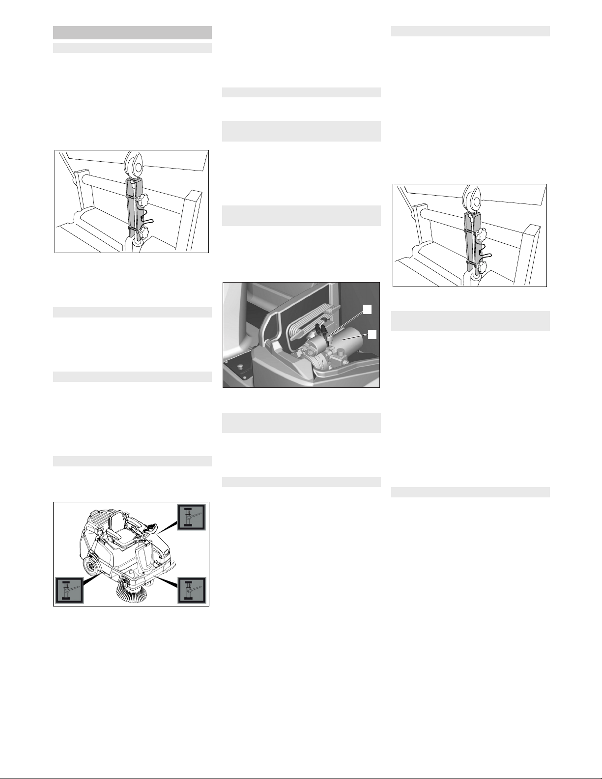
Park the machine on an even surface.
Check stability of ground. Lock the ap-
pliance to ensure that it does not roll off.
Illustration is symbolic, here KM 105/...
Place the jack at the relevant position
point.
NOTICE
Use a suitable commercially available vehi-
cle jack.
Loosen the central wheel bolt by ap-
prox. 1 rotation using a suitable tool.
Raise machine using vehicle jack.
Unscrew and remove the wheel bolt.
Remove wheel.
Have a defective wheel repaired or re-
placed in a specialist workshop.
Fit the wheel and screw the wheel bolt
all the way in and tighten it lightly.
Lower machine using vehicle jack.
Tighten the wheel bolt with the required
torque.
Tightening torque 49 Nm
Contact the customer service for the re-
moval of the drive.
Do not sit down on the driver seat.
Turn the programme selector switch to
position C (drive).
If the message >Please sit down on
the machine< appears on the display,
the safety function is given.
(only with devices with high emptying sys-
tem)
CAUTION
This inspection may only be carried out
when the machine has cooled down.
1 Hydraulic unit
2 Filler neck
Note: The side brush floating mounting ad-
justs the sweeping track as the bristles
wear down. The side brush must be re-
placed if it becomes too worn.
Recommendation: Replacing the side
brush at a remaining bristle length of ap-
prox. 10 cm.
Park the machine on an even surface.
Turn the programme selector switch to
"OFF" and remove the KIK-key.
Note: The side brush is raised.
Unscrew all 3 star grip nuts at the bot-
tom of the side brush by hand. For this
purpose reach through the bristles of
the side brush.
Remove the wiper blade.
Clip new side brushes on to driver and
screw on.
Park the sweeper on an even surface.
With appliance with low emptying
system:
Turn the programme selector switch to
"OFF" and remove the KIK-key.
Remove both waste containers.
With appliance with high emptying
system:
Turn the programme selector switch to
position C (drive).
Lift the waste container and secure by
means of cylinder support.
Turn the programme selector switch to
"OFF" and remove the KIK-key.
Remove belts or cords from roller
brush.
The sweeping track of the roller brush is au-
tomatically adjusted by a system called
TEACH.
The condition of the roller brush can be
shown on the display.
Turn the programme selector switch to
"ON".
Push the direction key "upwards" or
"downwards" until the display > usabil-
ity of the roller brush: ..%< appears.
Note: If the roller brush is heavily worn, the
indication >Usability of the roller brush
<25%< appears on the display.
Now, at the latest, the roller brush should
be replaced.
The replacement is required if the sweep-
ing result visibly decreases due to the wear
of the bristles or the indication >Usability
of the roller brush <25%< appears on the
display.
Each roller brush half is attached to the
shaft by means of 2 screws. Both halves
are identical, which facilitates the installa-
tion.
Park the machine on an even surface.
With appliance with low emptying sys-
tem:
Turn the programme selector switch to
"OFF" and remove the KIK-key.
Remove both waste containers.
Note: For the removal of the roller
brush dismount the centre bar first.
Loosen the screw and remove the cen-
tre bar.
Maintenance Works
General notes on safety
Preparation
Check the tyre pressure
Remove rear wheel
Dismantling the drive
Check the function of the seat contact
switch
Checking hydraulic oil level at the
hydraulic unit
Checking the sweeping mirror of the
side-brushes
Replacing side brush
2
1
Checking roller brush
Check the sweeping mirror of the
sweeping roller
Replacing the roller brush halves
39EN
-
15
With appliance with high emptying sys-
tem:
Turn the programme selector switch to
position C (drive).
Lift the waste container and secure by
means of cylinder support.
Turn the programme selector switch to
"OFF" and remove the KIK-key.
1 Screws
2 Roller brush
Unscrew both screws by hand and pull
the roller brush half from the shaft.
Insert new roller brush halves and tight-
en the screws (pay attention to the
marking "L" = left and "R" = right).
Turn the roller brush by 180 °, loosen
and remove the screws from the sec-
ond roller brush half.
Insert new roller brush half and tighten
the screws.
Then ensure that the roller brushes are
safely locked in place.
With appliance with low emptying sys-
tem:
Reattach the centre bar, ensure proper
seating of the gaskets!
Park the machine on an even surface.
Turn the programme selector switch to
"OFF" and remove the KIK-key.
Side brush and roller brush are raised.
1 Front sealing strip
2 Nut
3 Retaining plate front
4 Rear sealing strip
5 Screw
6 Forward travel direction
Front sealing strip
Adjusting the sealing strip:
Loosen the nuts by approx. 2 rotations,
do not completely unscrew them.
Set the distance between the sealing
strip and the floor so that the bottom
edge trails behind at a distance of be-
tween 80-85 mm.
Tighten nuts.
If worn, replace.
For replacing the sealing strips unscrew
the nuts completley, insert new sealing
strip, fit retaining plate, adjust sealing
strips and screw down retaining plate.
Rear sealing strip
Adjusting the sealing strip:
Loosen screws by approx. 2 rotations,
do not completely unscrew them.
Set the distance between the sealing
strip and the floor so that it tilts towards
the front with an overtravel of 15 -
20 mm.
Tighten the screws.
If worn, replace.
For replacing the sealing strips unscrew
the screws completley, insert new seal-
ing strip, fit retaining plate, adjust seal-
ing strips and screw down retaining
plate.
Side sealing strips
Adjusting the sealing strip:
Loosen screws by approx. 2 rotations,
do not completely unscrew them.
To set the floor clearance, insert a
sheet with a thickness of between 1 and
3 mm under the sealing strip.
Adjust sealing strip.
Tighten the screws.
If worn, replace.
For replacing the sealing strips unscrew
the screws completley, insert new seal-
ing strip, fit retaining plate, adjust seal-
ing strips and screw down retaining
plate.
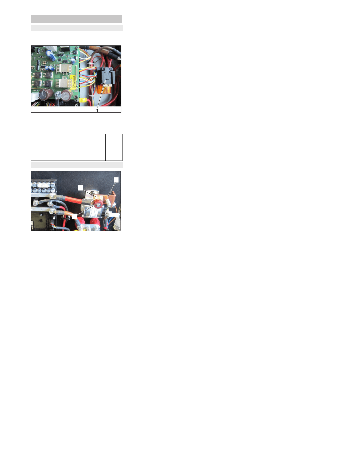
�
WARNING
Wear a dust mask when working around
the dust filter. Observe safety regulations
on the handling of fine particles.
� CAUTION
Risk of damage!
Do not rinse out the dust filter.
Note: Only clean the dust filter dry, careful-
ly knock out the dirt or blow it out with re-
duced compressed air.
Note: Wait at least 1 minute before remov-
ing the dust filter so that the dust can settle.
Figure: KM 125/... with 3 flat fold filters; KM
105/... has 2 flat fold filters
1 Lid with cleaning device
2 Screw
3 Support
4 Dust filter (flat-fold filter)
Unscrew the screw.
Fold the lid up and secure it by means
of the support.
Take out the dust filter.
Check dust filter.
Insert cleaned or new dust filter.
Place support into retainer.
Close the lid.
Screw in the screws and tighten them.
Have the suction blower checked for
leaks.
Check by customer service
Check the drive belt of the roller brush
for tension, wear and function.
Check by customer service
Adjusting and replacing sealing strips
80-85 mm
15-20 mm
1
2
4
5
6
3
Check/replace dust filter
Check suction blower
Checking drive belt of roller brush
40 EN
-
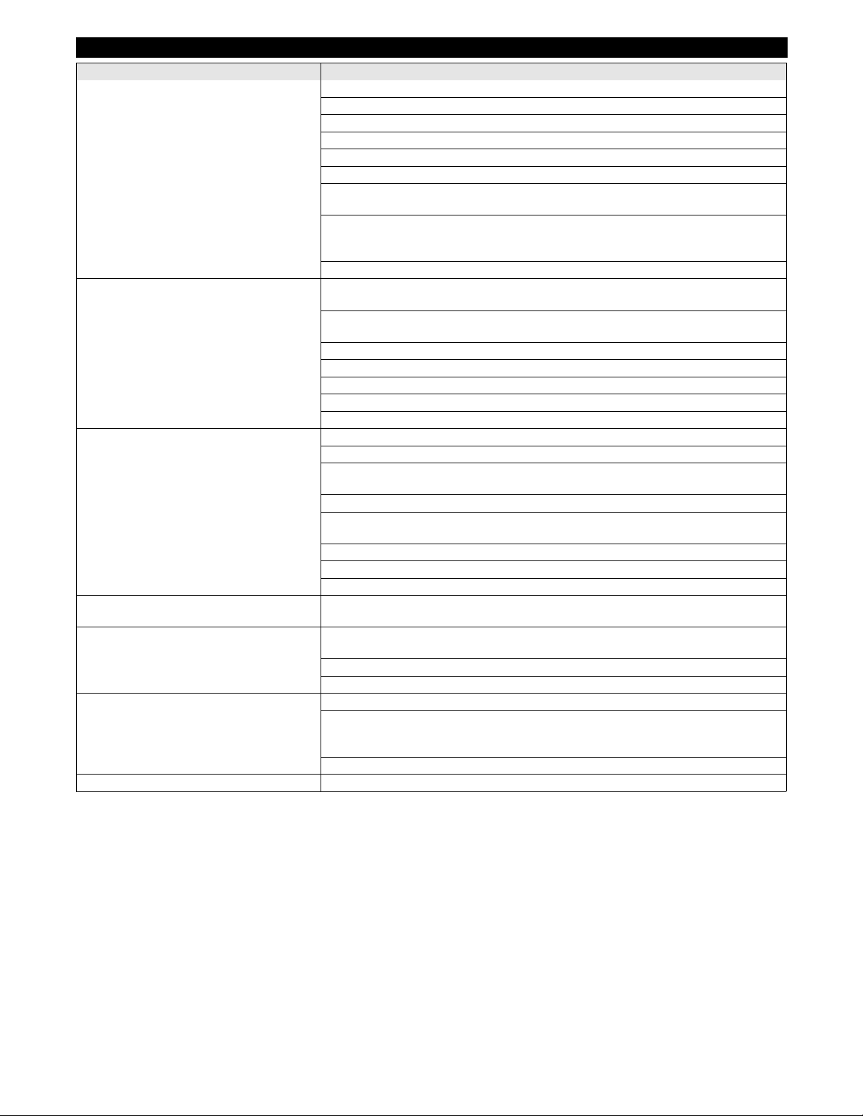
16
The fuses are located in the MFM box un-
derneath the driver seat.
1 Fuses
Open the cover of the MFM box.
Replace defective fuse.
1 Pole fuse
2 Jumper
3 Nut
Note:A defective pole fuse may only be re-
placed by a Kärcher service technician or
an authorised expert. If this fuse is defec-
tive, check the usage conditions and the
entire control system.
Fuses
Replacing fuses
F1 Control CPU 5 A
F2 Main fuse
Pole fuse
175 A
F70 Charger 40 A
Pole fuse
2
3
1
41EN
-
17
Troubleshooting
Failure Correction
Appliance cannot be started Turn the programme selector switch to position C (drive).
Sit on the driver seat, the seat contact switch gets activated.
Set main switch to “I/ON”.
Insert approved KIK-key (Kärcher Intelligent Key)
Insert battery plug.
Close left cover.
Properly insert the waste container (low emptying system) or completely tip it inwards and
lower it (high emptying system)
Check the charging state of the battery on the display (appears upon switching on the de-
vice).
Charge the battery if required.
Inform Kärcher Customer Service.
Machine is not sweeping properly Select sweeping programme, in order to do so, turn the programme selector switch to po-
sition D, E or F
Increase roller brush contact pressure; in order to do so, select sweeping programme
"MEDIUM" or "HEAVY" on the control panel.
Check roller brush and side brushes for wear, replace if necessary.
Check function of bulk waste flap
Check sealing strips for wear, adjust or replace as required
Check the roller brush halves for proper seating
Inform Kärcher Customer Service.
Dust gathers in the machine
Insufficient vacuum performance
Empty waste container
Switch on suction blower
Check dust filter, clean or replace
Do not rinse out the dust filter.
Check filter case seal
Check the function of the automatic filter cleaning device (see malfunction point "repeated
blowout bang audible"
Check the gaskets on the waste container
Check sealing strips for wear, adjust or replace as required
Inform Kärcher Customer Service.
Side brush or roller brush switch-on operation
is not working
Inform Kärcher Customer Service.
Roller brush does not turn.
Side brush does not turn
Select sweeping programme, in order to do so, turn the programme selector switch to po-
sition D, E or F
Check the roller brush and side brushes for wrapped belts.
Inform Kärcher Customer Service.
(High emptying system) waste container does
not retract/extend
Waste container cannot be tilted
Turn the programme selector switch to position C (drive).
Push and hold down the two-hand operation button on the left cover and the direction
keys on the control panel.
Note: Function reacts with a delay.
Inform Kärcher Customer Service.
A short blow-off sound can be heard. The appliance is OK, the automatic filter cleaning system is working
42 EN

-
18
Troubleshooting by the operator with plain text messages on the display
Note:
If the display messages shown remain despite the corrective measures described, contact service!
Display Meaning and consequence Corrective measures
1 Invalid KiK!
Operation locked
The identification of the inserted key is unknown.
– The appliance operation is prevented
Insert approved KIK-key (Kärcher Intelligent
Key)
2 Valid KiK but no
operation rights
The KIK-key (Kärcher Intelligent Key) is known, howev-
er not approved for this appliance.
– The appliance operation is prevented
Insert approved KIK-key (Kärcher Intelligent
Key)
Programme the key with the Supervisor Intelli-
gent Key.
3 High dump tracer
stuck! Check it!
The function of the two-hand operation button is
checked for its safety function when the appliance is
switched on.
– When the two-hand operation button is pushed, the
operation is prevented during start-up
Release the two-hand operation button.
Confirm the message with the OK key (delete).
4 Locked HD-tracer The two-hand operation button (high emptying system)
was pushed in a sweeping programme.
– High emptying is prevented in the sweeping pro-
gramme for safety reasons.
Release the two-hand operation button.
Turn the programme selector switch to position
C (drive).
Press the two-hand operation button and keep it
down.
Operate the high emptying system by means of
the direction keys.
5 Sit on machine
for operation!
Appears when a sweeping or transport programme is
selected upon starting up the machine and no operator
is sitting on the seat.
– All unit functions are prevented
Sit on the driver's seat.
Note: The selected sweeping / transport opera-
tion starts fully automated.
Note: This procedure simultaneously serves the
inspection of the safety function of the seat
switch!
7 Dirt pan open! Is displayed (low emptying system) as soon as a trans-
port or sweeping programme has been selected and at
least one waste container is removed.
– All unit functions are prevented
Lock all waste containers in place.
Turn the programme selector switch to "ON".
Note: The message disappears. The appliance
is ready for operation.
8 Dirt pan open? Is displayed (high emptying system) as soon as a
sweeping programme has been selected and the waste
container is not fully retracted and tipped inwards.
– All sweeping functions are prevented.
Turn the programme selector switch to position
C (drive).
Press the two-hand operation button and keep it
down.
If necessary, tip the waste container inwards
and then lower it by means of the direction keys.
Note: In case of an attempt to completely lower a con-
tainer that is tipped outwards, a collision monitoring sys-
tem prevents the high emptying system from being dam-
aged
Release the two-hand operation button and the
direction keys.
Press the two-hand operation button and keep it
down.
Completely tip the container inwards by means
of the direction keys before lowering it.
Note: In case of an attempt to tip a retracted container
outwards, a collision monitoring system prevents the
high emptying system from being damaged
Release the two-hand operation button and the
direction keys.
Press the two-hand operation button and keep it
down.
Sufficiently raise the container by means of the
direction keys before it can be tipped outwards.
9 Brushpos. not ok Is displayed when the roller brush cannot move to the
factory-set end position.
– The appliance is ready for operation, however, the
sweeping result may be dissatisfying
Confirm the message with the OK key (delete).
Turn the programme selector switch to position
C (drive).
Change to the desired sweeping programme
again.
10 RBroompos.not ok Is displayed when the right side brush cannot move to
the factory-set end position.
– The appliance is ready for operation, however, the
sweeping result may be dissatisfying or the right side
brush may not be raised
Confirm the message with the OK key (delete).
Turn the programme selector switch to position
C (drive).
Change to the desired sweeping programme
again.
11 LBroompos.not ok Is displayed when the optionally available left side brush
cannot move to the factory-set end position.
– The appliance is ready for operation, however, the
sweeping result may be dissatisfying or the left side
brush may not be raised
Confirm the message with the OK key (delete).
Turn the programme selector switch to position
C (drive).
Change to the desired sweeping programme
again.
43EN
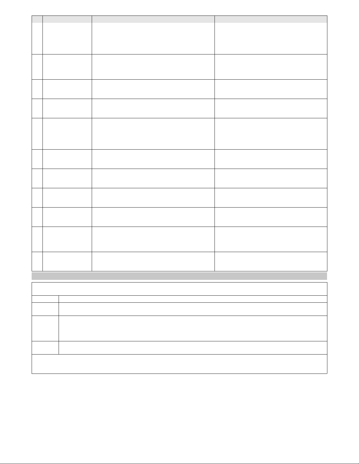
-
19
12 SBroompos.not ok Is displayed when the optionally available sickle brush
cannot move to the factory-set end position.
– The appliance is ready for operation, however, the
sweeping result may be dissatisfying or the sickle brush
may not be raised
Confirm the message with the OK key (delete).
Turn the programme selector switch to position
C (drive).
Change to the desired sweeping programme
again.
13 Seat switch open Appears if the seat is left for more than 1.5 seconds in
drive mode.
– Device switches off, all brushes and the roller brush
that are lowered to the ground are raised automatically
Sit on the driver's seat.
Note: The selected sweeping / transport opera-
tion starts fully automated.
14 Usable sweeping
brush <25%
Appears if the roller brush has reached its wear limit.
– The appliance is ready for operation, however, the
sweeping result may be dissatisfying
Replace the roller brush as soon as possible to
achieve a good sweeping result.
15 MF-module not
ready to use x
Appears if the control panel has no connection to the
machine control.
– The operation of the appliance is disabled
Perform a programme selector switch reset
(OFF position).
16 Motorhood open! Appears if the left side cover is not properly locked in
place.
– The operation of the appliance is disabled
Completely close the left cover and lock in
place.
Turn the programme selector switch to "ON".
Note: The message disappears. The appliance
is ready for operation.
18 Charge battery! Appears if the battery voltage is low.
– All sweeping functions are switched off, the appliance
is still running
Note: The message can no longer be confirmed.
Charge battery.
19 BAT shut-down Appears if the battery is empty.
– The operation of the device is prevented for the protec-
tion of the battery, device can no longer be driven.
Charge battery.
20 Firmware update
firmware update!
Appears if the machine control has detected a safety-
critical error during the self test.
– The operation of the appliance is disabled
Call service!
22 Call service!
+xx-xxxx-xx-xxxx
The inspection interval has lapsed. This message ap-
pears upon every start-up of the appliance.
– The appliance remains fully operational
Confirm the message with the OK key (delete).
Contact your local service for inspection under
the displayed phone number.
23 Red 0/1 switch=0
Operation locked
The message appears both during operation and start-
up of the appliance if the red main switch is in the "0" po-
sition.
– The appliance operation is prevented
Set main switch to “I/ON”.
24 Easy oper.switch
must be OFF next
This message appears in connection with message 23. For safety reasons the start-up of the appliance
requires the switching-off of the programme se-
lector switch (OFF position)!
Display Meaning and consequence Corrective measures
Troubleshooting with coded error message on the display
Note:
A coded error message is always displayed in the upper display line and has the following formats:
X yyy Identification letter X followed by up to 3 digits yyy
e.g.
S 110
There is a system error that completely or partly disables the appliance function.
e.g.
P 3
C 41
H 2
There is an error in the machine control. Individual or several appliance functions are disabled.
e.g.
F/11
Make sure that there is no more than 1 KIK-key (Kärcher Intelligent Key) near the control panel.
If a coded error occurs, try resetting the programme selector switch first.
In order to do so, turn the programme selector switch in the "OFF" position. Wait for at least 5 seconds before restarting the appliance.
If the error is still pending, contact service. The indication of the error code may be helpful for the service!
44 EN
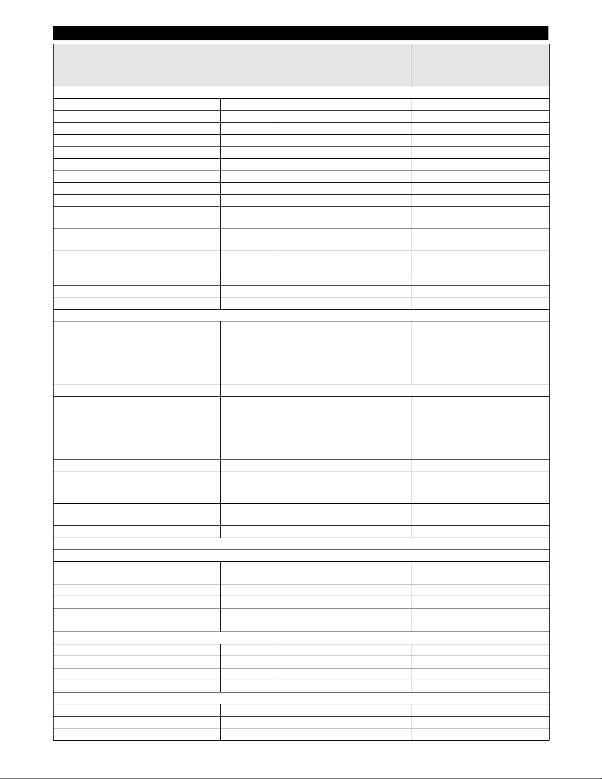
-
20
Specifications
KM 105/100 R Bp
KM 105/110 R Bp
KM 105/100 R Bp Pack
KM 105/110 R Bp Pack
KM 125/130 R Bp
KM 125/130 R Bp Pack
Machine data
Length x width x height mm 1800 x 1250 x 1450 1800 x 1500 x 1450
Driving speed km/h 6 8
Cleaning speed km/h 4 4
Usage duration with battery fully charged h ca. 2,5 ca. 2,5
Climbing capability (max.) % 12 12
Turning radius m 2,70 3,00
Roller brush diameter mm 400 400
Roller brush width mm 640 880
Side brush diameter mm 600 600
Surface cleaning performance without side
brushes
m
2
/h 3840 7040
Surface cleaning performance with 1 side
brushes
m
2
/h 6300 10000
Surface cleaning performance with 2 side
brushes
m
2
/h 8700 13600
Working width without side brushes mm 640 880
Working width with 1 side brushes mm 1050 1250
Working width with 2 side brushes mm 1450 1700
Net weight (transport weight)
KM 105/100 R Bp
KM 105/110 R Bp
KM 105/100 R Bp Pack
KM 105/110 R Bp Pack
KM 125/130 R Bp
KM 125/130 R Bp Pack
kg
kg
kg
kg
kg
kg
305
405
490
590
---
---
---
---
---
---
500
820
Permissible overall weight
KM 105/100 R Bp
KM 105/110 R Bp
KM 105/100 R Bp Pack
KM 105/110 R Bp Pack
KM 125/130 R Bp
KM 125/130 R Bp Pack
kg
kg
kg
kg
kg
kg
725
725
825
825
---
---
---
---
---
---
1060
1060
Volume of waste container
KM 105/100 R (low emptying system)
KM 105/110 R (high emptying system)
KM 125/130 R (high emptying system)
l (kg)
l (kg)
l (kg)
2 x 35 (2 x 50)
80 (100)
---
---
---
110 (150)
Maximum unloading height (high emptying
system)
mm 1550 1550
Protection type, drip-proof -- IPX 3 IPX 3
Motors
– Drive motor
Type -- DC permanent solenoid motor for
front and reverse drive
DC permanent solenoid motor for
front and reverse drive
Type -- Wheel hub motor in front wheel Wheel hub motor in front wheel
Voltage V 24 24
Rated power (mechanical) W 750 1000
Speed 1/min Phaseless Phaseless
– Blower motor
Type -- DC permanent solenoid motor DC permanent solenoid motor
Voltage V 24 24
Rated power (mechanical) W 200 200
Speed 1/min 3500 3500
– Roller brush motor
Type -- DC permanent solenoid motor DC permanent solenoid motor
Voltage V 24 24
Rated power (mechanical) W 750 1100
45EN
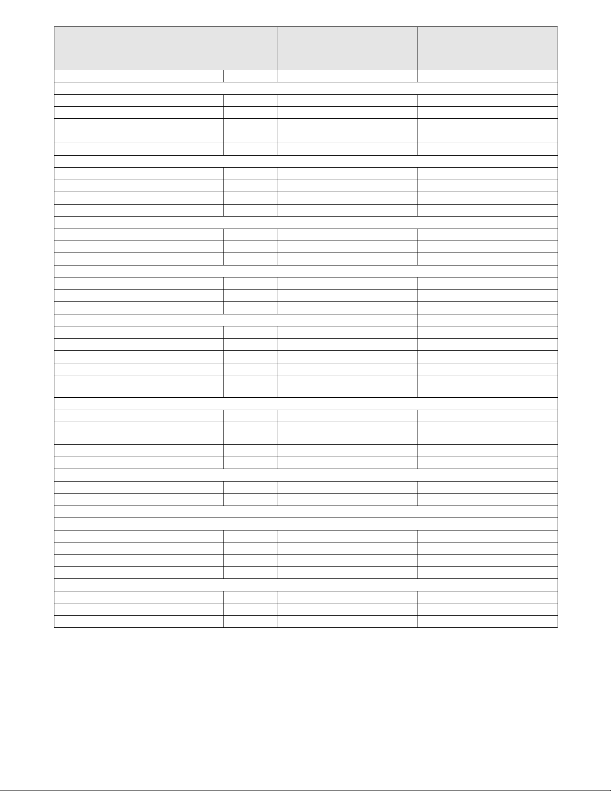
-
21
Speed 1/min 500 (at the roller brush) 500 (at the roller brush)
– Side brush motor
Type -- DC permanent solenoid motor DC permanent solenoid motor
Type -- Drive motor (angular drive) Drive motor (angular drive)
Voltage V 24 24
Rated power (mechanical) W 240 240
Speed 1/min 65 65
Battery (only Pack variants)
Type -- 24V 4 PzS 240 I 24V 4 PzS 240 I
Capacity Ah 240 240
Charging time for fully discharged battery h 10...15 10...15
Operating time after frequent charging h ca. 2,5 ca. 2,5
Charger (only Pack variants)
Mains voltage V~ 230 230
Output voltage V 24 24
Output current A 30 30
Fuses
Main fuse A 175 175
Control CPU A 5 5
Charger A 40 40
Tyres
Size, rear -- 4.00-8 8PR 4.00-8 8PR
Air pressure, rear bar 6,0 6,0
Brake
Service brake -- electronic electronic
Parking brake -- Disc brake, operated electrically (with
spring)
Disc brake, operated electrically (with
spring)
Filter and vacuum system
Filter system TACT TACT
Category of use – filter for non-hazardous
dust
-- M M
Nominal vacuum, suction system mbar 6 6
Nominal volume flow, suction system l/s 92 92
Working conditions
Temperature °C -5...+ 40 -5...+ 40
Air humidity, non-condensing % 0 - 90 0 - 90
Values determined as per EN 60335-2-72
Noise emission
Sound pressure level L
pA
dB(A) 64 71
Uncertainty K
pA
dB(A) 3 3
Sound power level L
WA
+ Uncertainty K
WA
dB(A) 83 90
Uncertainty K
WA
3 3
Machine vibrations
Hand-arm vibration value m/s
2
< 2,5 < 2,5
Seat m/s
2
0,4 0,4
Uncertainty K m/s
2
0,2 0,2
KM 105/100 R Bp
KM 105/110 R Bp
KM 105/100 R Bp Pack
KM 105/110 R Bp Pack
KM 125/130 R Bp
KM 125/130 R Bp Pack
46 EN
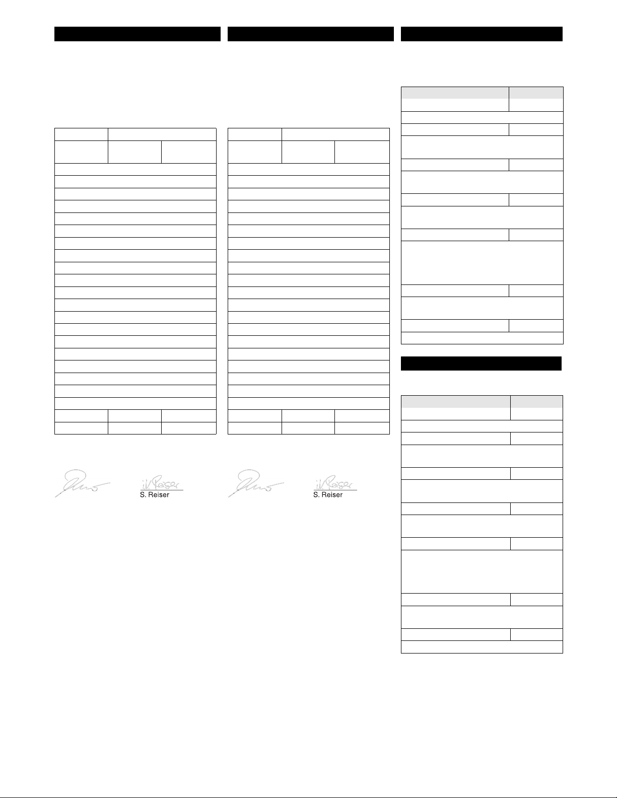
-
22
We hereby declare that the machine de-
scribed below complies with the relevant
basic safety and health requirements of the
EU Directives, both in its basic design and
construction as well as in the version put
into circulation by us. This declaration shall
cease to be valid if the machine is modified
without our prior approval.
The signatories act on behalf of and with of
the authority of the company management.
Documentation supervisor:
S. Reiser
Alfred Kärcher SE & Co. KG
Alfred-Kärcher-Straße 28-40
71364 Winnenden (Germany)
Tel.: +49 7195 14-0
Fax: +49 7195 14-2212
Winnenden, 2022/02/01
We hereby declare that the product de-
scribed below complies with the relevant
provisions of the following UK Regulations,
both in its basic design and construction as
well as in the version put into circulation by
us. This declaration shall cease to be valid
if the product is modified without our prior
approval.
The signatories act on behalf of and with of
the authority of the company management.
Documentation supervisor:
S. Reiser
Alfred Kärcher SE & Co. KG
Alfred-Kärcher-Straße 28-40
71364 Winnenden (Germany)
Tel.: +49 7195 14-0
Fax: +49 7195 14-2212
Winnenden, 2022/02/01
KM 105/100 R Bp
KM 105/110 R Bp
KM 105/100 R Bp Pack
KM 105/110 R Bp Pack
KM 125/130 R Bp
KM 125/130 R Bp Pack
EU Declaration of Conformity
Product: Vacuum sweeper
Type: 1.280-xxx
KM 105/...
1.280-xxx
KM 125/130..
Relevant EU Directives
2006/42/EC (+2009/127/EC)
2014/30/EU
2000/14/EC
2014/53/EU
Applied harmonized standards
EN 60335–1
EN 60335–2–72
EN 62233: 2008
EN 55012: 2007 + A1: 2009
EN 61000–6–2: 2005
TCU
EN 300 328 V2.2.2
EN 300 330 V2.1.1
EN 300 440 V2.1.1
EN 301 511 V12.5.1
Applied conformity evaluation method
2000/14/EC: Appendix V
Sound power level dB(A)
Bp
Measured: 80 87
Guaranteed: 83 90
Chairman of the Board of Management
Director Regulatory Affairs & Certification
Declaration of Conformity
Product: Vacuum sweeper
Type: 1.280-xxx
KM 105/...
1.280-xxx
KM 125/130..
Currently applicable UK Regulations
S.I. 2008/1597 (as amended)
S.I. 2016/1091 (as amended)
S.I. 2001/1701 (as amended)
S.I. 2017/1206 (as amended)
Designated standards used
EN 60335–1
EN 60335–2–72
EN 62233: 2008
EN 55012: 2007 + A1: 2009
EN 61000–6–2: 2005
TCU
EN 300 328 V2.2.2
EN 300 330 V2.1.1
EN 300 440 V2.1.1
EN 301 511 V12.5.1
Applied conformity assessment procedure
S.I. 2001/1701 (as amended): Schedule 8
Sound power level dB(A)
Bp
Measured: 80 87
Guaranteed: 83 90
Chairman of the Board of Management
Director Regulatory Affairs & Certification
Accessories (KM 105/...)
Name Order No.
Side brushes, standard 6.966-063.0
For cleaning of indoor and outdoor areas.
Hard side-brushes 6.906-705.0
For removing stubborn dirt in the external
area; resistant to moisture.
Side-brushes, soft 6.966-065.0
Especially for sweeping fine dust on even
floors.
Roller brush, standard 4.762-529.0
Resistant of wear and moisture. Universal
bristles for inside and outside cleaning.
Roller-brush, soft 4.762-523.0
With natural bristles especially for fine dust
sweeping on smooth indoor floors. Not re-
sistant to wetness; not for abrasive surfac-
es.
Roller-brush, hard 4.762-524.0
For removing stubborn dirt in the external
area; resistant to moisture.
Flat-fold filter (dust filter) 4.730-004.0
Machine requires 2 units
Accessories (KM 125/...)
Name Order No.
Side brushes, standard 6.966-063.0
For cleaning of indoor and outdoor areas.
Hard side-brushes 6.906-705.0
For removing stubborn dirt in the external
area; resistant to moisture.
Side-brushes, soft 6.966-065.0
Especially for sweeping fine dust on even
floors.
Roller brush, standard 4.762-525.0
Resistant of wear and moisture. Universal
bristles for inside and outside cleaning.
Roller-brush, soft 4.762-526.0
With natural bristles especially for fine dust
sweeping on smooth indoor floors. Not re-
sistant to wetness; not for abrasive surfac-
es.
Roller-brush, hard 4.762-527.0
For removing stubborn dirt in the external
area; resistant to moisture.
Flat-fold filter (dust filter) 4.730-004.0
Machine requires 3 units
47EN