Loading ...
Loading ...
Loading ...
ASSEMBLY
AssembJy requires two persons. Set the treadmHUin a cleared area and remove aH packing matedaUs, Do not
dispose of the packing matedaJs until assemMy is completed.
Note: The underside of the treadmHUwaUking beUtis coated with high-performance Uubdcant, During shipping, a
small amount of Uubdcant may be transferred to the top of the waUking beUtor the shipping carton, This is a normaU
condition and does not affect treadmHUperformance, Ufthere is Uubdcant on top of the waUMng beUt,simpUy wipe off
the lubricant with a soft cloth and a mild, non-abrasive cleaner,
Assembly requires the included allen wrench _ and your own phillips screwdriver __ and
wire cutters _: _._. For help identifying the assembly hardware, see the hardware drawings beJow.
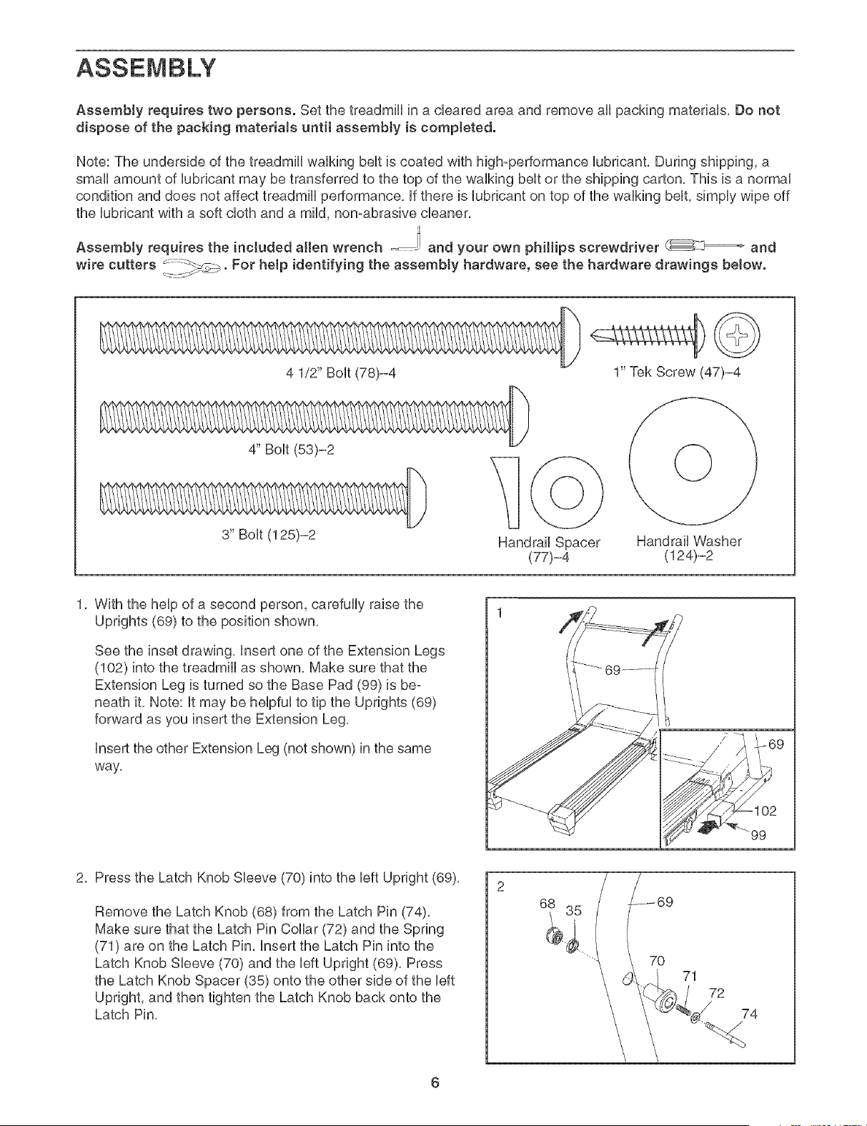
4 1/2" Bolt (78)-4 1" Tek Screw (47)-4
4" Bolt (53)-2
3" Bolt (125)-2 Handrail Spacer
(77)-4
Handrail VVasher
(124)-2
1, With the help of a second person, carefully raise the
Uprights (69) to the position shown,
See the inset drawing, insert one of the Extension Legs
(102) into the treadmill as shown, Make sure that the
Extension Leg is turned so the Base Pad (99) is be-
neath it, Note: it may be helpful to tip the Uprights (69)
forward as you insert the Extension Leg,
Insert the other Extension Leg (not shown) in the same
way.
99
2, Press the Latch Knob Sleeve (70) into the left Upright (69),
Remove the Latch Knob (68) from the Latch Pin (74).
Make sure that the Latch Pin Collar (72) and the Spring
(71) are on the Latch Pin, Insert the Latch Pin into the
Latch Knob Sleeve (70) and the left Upright (69), Press
the Latch Knob Spacer (35) onto the other side of the left
Upright, and then tighten the Latch Knob back onto the
Latch Pin,
71
72
74
6
Loading ...
Loading ...
Loading ...