Owner's Manual
iCRHFTSMRN'i
Permanently Lubricated
Twin V
2-Stage
Stationary
AIR COMPRESSOR
Model No.
919.165612
• Safety Guidelines
• Assembly
• Operation
• Maintenance
• Troubleshooting
• Repair Parts
CAUTION: Read the Safety Guidelines
and All Instructions Carefully Before
Operating.
Sears, Roebuck and Co., Hoffman Estates, IL 60179 U.S.A.
Visit our Craftsman website: www.sears.com/craftsman
D30088 Rev. 0 9/26/03

WARRANTY ................................................ 2
SPECIFICATION CHART ..................................... 3
SAFETY GUIDELINES-DEFINITIONS ........................... 3
IMPORTANT SAFETY INSTRUCTIONS ........................ 3-8
GLOSSARY ................................................ 9
ACCESSORIES ............................................. 9
DUTY CYCLE .............................................. 9
ASSEMBLY ............................................... 10
INSTALLATION .......................................... 10-12
OPERATION ............................................ 13-15
MAINTENANCE ......................................... 16-17
SERVICE AND ADJUSTMENTS ............................... 18
STORAGE ................................................ 19
TROUBLESHOOTING GUIDE .............................. 20-22
REPAIR PARTS ......................................... 23-27
REPAIR PROTECTION AGREEMENTS ......................... 51
HOW TO ORDER REPAIR PARTS ............................. 28
FULL ONE YEAR WARRANTY AIR COMPRESSOR
If this CRAFTSMAN Air Compressor fails due to a defect in material or
workmanship within one year from the date of purchase, Sears will at its
option repair or replace it free of charge. Contact your nearest Sears Service
Center (1-800-4-MY-HOME ®)to arrange for repair, or return the Air
Compressor to the place of purchase for replacement.
If this Air Compressor is used for commercial or rental purposes, this warrant
applies for only ninety days from the date of purchase.
This warranty gives you specific legal rights and you may have other rights
which vary from state to state.
Sears, Roebuck and Co., Dept. 817WA, Hoffman Estates, IL 60179
D30088 2* ENG
-1_ =let I_1[e_,__lII[o]_I[e_-"F__:tl
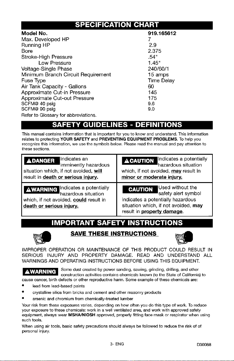
Model No. 919.165612
Max. Developed HP 7
Running HP 2.9
Bore 2.375
Stroke-High Pressure .54"
Low Pressure 1.45"
Voltage-Single Phase 240/60/1
Minimum Branch Circuit Requirement 15 amps
Fuse Type Time Delay
Air Tank Capacity - Gallons 60
Approximate Cut-in Pressure 145
Approximate Cut-out Pressure 175
SCFM@40 psig 9.6
SCFM@90 psig 9.0
Referto Glossary for abbreviations
[.'-Yz1_l_l_'l_tl]lm]=lll#l=B-]. Im]=l_ll#lbll[o_]_:-]
This manual contains information that iS important for you to know and understand. This information
relates to protecting YOUR SAFETY and PREVENTING EQUIPMENT PROBLEMS, To help you
recognize this information_ we use the symbols below, Please read the manual and pay attention to
these sections.
_'_ Indicates an
imminently hazardous
situation which, if not avoided, will
result in death or serious injurv.
_lndicates a potentially
hazardous situation
which, if not avoided, could result in
death or serious injury.
_lndicates a potentially
hazardous situation
which, if not avoided, _ result in
minor or moderate injury.
_"_lUsed without the
safety alert symbol
indicates a potentially hazardous
situation which, if not avoided, may
result in oroDertv damaae.
Ih_l_o]-'tpL+_+hnl£:'/.,_al_S'd_[IP.[-:-]ljt,ttl_o,]njl[o_]P.[-.+
SAVE THESE INSTRUCTIONS
IMPROPER OPERATION OR MAINTENANCE OF THIS PRODUCT COULD RESULTIN
SERIOUS INJURY AND PROPERTY DAMAGE. READ AND UNDERSTAND ALL
WARNINGSAND OPERATINGINSTRUCTIONSBEFOREUSINGTHIS EQUIPMENT.
Some dust created by power sanding, sawing, grinding, drilling, and other
construction activities contains chemicals known (to the State of California) to
cause cancer, birth defects or other reproductive harm, Some example of these chemicals are:
• lead from lead-based paints
• crystalline silica from bricks and cement and other masonry products
• arsenic and chromium from chemically*treated lumber
Your risk from these exposures varies, depending on how often you do this type of work. To reduce
your exposure to these chemicals: work in a well ventilated area, and work with approved safety
equipment, always wear MSHA/NIOSH approved, properly fitting face mask or respirator when using
such tools.
When using air tools, basic safety precautions should always be followed to reduce the risk of of
personal injury.
3* ENG D30088

II_ I_o] ;111P'.'q+IInl[,.'9'.,__1_ &'i __JL_[,._)III,_]LI_+']IIT[_o_+]L_,[,._
Save these instructions
Improper operation or maintenance of this product could result in serious injury and
property damage. Read and understand all warnings and operation instructions before
using this equipment,
,l;1"l'J "-In
WARNING: Risk of explosion or fire
What Could Happen How To Prevent It
It is normal for electrical contacts Always operate the compressor in a well
within the motor and pressure switch to ventilated area free of combustible
spark, materials, gasoline, or solvent vapors.
If electrical sparks from compressor If spraying flammable materials, locate
come into contact with flammable compressor at least 20 feet away from
vapors, they may ignite, causing fire or spray area. An additional length of hose
explosion, may be required,
Store flammable materials in a secure
location away from compressor.
Restricting any of the compressor
ventilation openings will cause serious
overheating and could cause fire,
Unattended operation of this product
could result in personal injury or
property damage. To reduce the risk of
fire, do not allow the compressor to
operate unattended.
Never place objects against or on top
of compressor. Operate compressor in
an open area at least 12 inches away
from any wall or obstruction that would
restrict the flow of fresh air to the
ventilation openings.
Operate compressor in a clean, dry wall
ventilated area. Do not operate unit
indoors or in any confined area.
Always remain in attendance with the
)roduct when it is operating.
Always disconnect electrical power by
moving pressure switch lever to the off
}osition and drain tank daily or after
each use.
D30088 4* ENG
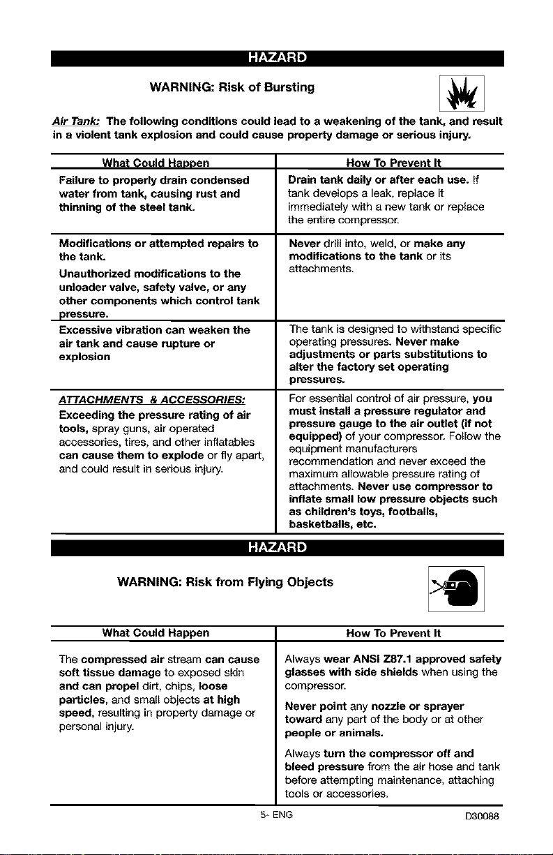
WARNING: Risk of Bursting
Air Tank: The following conditions could lead to a weakening of the tank, and result
in a violent tank explosion and could cause property damage or serious injury,
What Could Haopen How To Prevent It
Failure to properly drain condensed Drain tank daily or after each use. If
water from tank, causing rust and tank develops a leak, replace it
thinning of the steel tank. immediately with a new tank or replace
the entire compressor.
Modifications or attempted repairs to Never drill into, weld, or make any
the tank. modifications to the tank or its
Unauthorized modifications to the attachments.
unloader valve, safety valve, or any
other components which control tank
pressure.
Excessive vibration can weaken the The tank is designed to withstand specific
air tank and cause rupture or operating pressures. Never make
explosion adjustments or parts substitutions to
alter the factory set operating
pressures=
ATTACHMENTS & ACCESSORIES:
Exceeding the pressure rating of air
tools, spray guns, air operated
accessories, tires, and other inflatables
can cause them to explode or fly apart,
and could result in serious injury.
For essential control of air pressure, you
must install a pressure regulator and
pressure gauge to the air outlet (if not
equipped) of your compressor. Follow the
equipment manufacturers
recommendation and never exceed the
maximum allowable pressure rating of
attachments. Never use compressor to
inflate small low pressure objects such
as children's toys, footballs,
basketballs, etc.
WARNING: Risk from Flying Objects
What Could Happen How To Prevent It
The compressed air stream can cause
soft tissue damage to exposed skin
and can propel dirt, chips, loose
particles, and small objects at high
speed, resulting in property damage or
personal injury.
Always wear ANSI Z87.1 approved safety
glasses with side shields when using the
compressor.
Never point any nozzle or sprayer
toward any part of the body or at other
people or animals.
Always turn the compressor off and
bleed pressure from the air hose and tank
before attempting maintenance, attaching
to0_s Oi" accessories,
5* ENG D30088
:f:1"4_;ll
WARNING: Risk of Electrical Shock
What Could Happen
Your air compressor is powered by
electricity. Like any other electrically
powered device, If it is not used
properly it may cause electric shock.
Repairs attempted by unqualified
personnel can result in serious injury
or death by electrocution.
Electrical Grounding: Failure to provide
adequate grounding to this product
could result in serious injury or death
from electrocution.
See grounding instructions,
How To Prevent It
Never operate the compressor outdoors
when it is raining or in wet conditions.
Never operate compressor with
protective covers removed or damaged.
Any electrical wiring or repairs required
on this product should be performed by
authorized service center personnel in
accordance with national and local
electrical codes,
Make certain that the electrical circuit to
which the compressor is connected
provides proper electrical grounding,
correct voltage and adequate fuse
protection.
WARNING: Risk of Breathing
What Could Happen How To Prevent It
The compressed air directly from your
compressor is not safe for breathing.
The air stream may contain carbon
monoxide, toxic vapors, or solid
particles from the tank. Breathing these
contaminants can cause serious injury
or death.
Sprayed materials such as paint, paint
solvents, paint remover, insecticides,
weed killers, may contain harmful
vapors and poisons,
Air obtained directly from the compressor
should never be used to supply air for
human consumption, in order to use air
produced by this compressor for
breathing, suitable filters and in-line
safety equipment must be properly
installed. In-line filters and safety
equipment used in conjunction with the
compressor must be capable of treating
air to all applicable local and federal
codes prior to human consumption.
Work in an area with good cross
ventilation. Read and follow the safety
instructions provided on the label or
safety data sheets for the materials you
are spraying. Use a NtOSH/MSHA
approved respirator designed for use with
your specific application.
D30088 6* ENG
WARNING: Risk of Burns
What Could Happen
Touching exposed metal such as the
compressor head or outlet tubes, can
result in serious burns.
How To Prevent It
Never touch any exposed metal parts
on compressor during or immediately
after operation. Compressor will remain
hot for several minutes after operation.
Do not reach around protective shrouds
or attempt maintenance until unit has
been allowed to cool.
;f.,v#.,1"1=
WARNING: Risk from Moving Parts _)
What Could Happen How To Prevent It
Moving parts such as the pulley, flywheel, Never operate the compressor with
and belt can cause serious injury if they guards or covers which are damaged or
come into contact with you or your removed.
clothing.
Attempting to operate compressor with Any repairs required on this product
damaged or missing parts or attempting should be performed by authorized
to repair compressor with protective service center personnel.
shrouds removed can expose you to
moving parts and can result in serious
injury,
;f.,VN.,I"1=
WARNING: Risk of Falling
What Could Happen
A portable compressor can fall from a
table, workbench, or roof causing
damage to the compressor and could
result in serious injury or death to the
operator.
How To Prevent It
Always operate compressor in a stable
secure position to prevent accidental
movement of the unit. Never operate
compressor on e roof or other elevated
position. Use additional air hose to
reach high locations.
7÷ ENG D30088
WARNING: Risk of Serious Injury or Property Damage When
Transporting Compressor
(Fire, Inhalation, Damage to VehicleSurfaces)
What Could Happen How To Prevent It
Oil can leak or spill and could result in Always place COMPRESSOR on a
fire or breathing hazard; serious injury or protective mat when transporting to
death can result, oil leaks will damage protect against damage to vehicle from
carpet, paint or other surfaces in leaks. Remove COMPRESSOR from
vehicles or trailers, vehicle immediately upon arrival at your
destination.
WARNING: Risk of Unsafe Operation _1=
What Could Happen How To Prevent It
Unsafe operation of your air compressor
could lead to serious injury or death to
you or others.
Review and understand all instructions
and warnings in this manual.
Become familiar with the operation and
controls of the air compressor.
Keep operating area clear of all persons,
pets, and obstacles.
Keep children away from the air
compressor at all times.
Do not operate the product when
fatigued or under the influence of
alcohol or drugs. Stay alert at all times.
Never defeat the safety features of this
product.
Equip area of operation with a fire
extinguisher.
DO not operate machine with missing,
broken, or unauthorized parts.
SAVE THESE INSTRUCTIONS
D30088 8* ENG
Become familiar with these terms
before operating the unit.
CFM: Cubic feet per minute.
SCFM: Standard cubic feet per
minute; a unit of measure of air
delivery.
PSlG: Pounds per square inch
gauge; a unit of measure of pressure.
Code Certification: Products that
bear one or more of the following
marks: UL, CUL, ETL, CETL, have
been evaluated by OSHA certified
independent safety laboratories and
meet the applicable Underwriters
Laboratories Standards for Safety.
Cut-In Pressure: While the motor is
off, air tank pressure drops as you
continue to use your accessory.
When the tank pressure drops to a
certain low level the motor will restart
automatically. The low pressure at
which the motor automatically
restarts is called "cut-in" pressure.
Cut-Out Pressure: When an air
compressor is turned on and begins
to run, air pressure in the air tank
begins to build, it builds to a certain
high pressure before the motor
automatically shuts off - protecting
your air tank from pressure higher
than its capacity. The high pressure
at which the motor shuts off is called
"cut-out" pressure.
Branch Circuit: Circuit carrying
electricity from electrical panel to
outlet.
The accessories and tools are
available through the current Power
and Hand Tool Catalog or full-line
Sears stores.
Accessories
• In Line Filter
• Tire Air Chuck
• Quick Connector Sets
(various sizes)
• Air Pressure Regulators
• Oil Fog Lubricators
• Air Hose:
1/4", 3/8" OR 1/2" I.D.
in various lengths
Refer to the selection chart located
on the unit to select the tools this unit
is capable of powering.
mL__luJnkTd[e,_ q=1
This air compressor pump is capable
of running continuously. However, to
prolong the life of your air
compressor, it is recommended that a
50%-75% average duty cycle be
maintained; that is, the air
compressor pump should not run
more than 30-45 minutes in any given
hour.
9- ENG D30088
Contents of Carton
1 - Air Compressor
1 - Parts bag containing:
1 - Operator's Manual
1 - Parts Manual
4- 5/8" Washers
Tools Required for Assembly
1 - 9/16" socket or open end wrench
Electric drill
Unpacking
1. Remove all packaging.
Risk of Unsafe
Opertation. It may
be necessary to brace or support
one side of the unit when removing
the pallet because the air
compressor will have a tendency
to tip,
2. Remove and discard the (4)
screws and washers holding the
compressor to the pallet.
3. With the help of another person
carefully remove air compressor
from pallet and place on a level
surface.
II__.']1L,III Ir.,tiI[o_
HOW TO SET UP YOUR
UNIT
Location of the Air Compressor
• Locate the air compressor in a
clean, dry, and well ventilated
area.
• Located the air compressor at
least 12" away from the wall or
other obstructions that will
interfere with the flow of air.
• Locate the air compressor as
close to the main power supply
as possible to avoid using long
lengths of electrical wiring.
NOTE: Long lengths of electrical
wiring could cause power loss to
the motor.
• The air filter must be kept clear
of obstructions which could
reduce air flow to the air
compressor.
Anchoring of the Air
Compressor
IF_qPJI_'R_I Risk of Unsafe
Bursting. Excessive
Vibration can weaken the air tank
and cause an explosion. The
compressor must be properly
mounted.
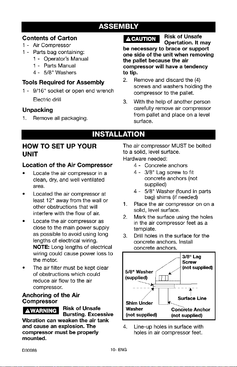
The air compressor MUST be bolted
to a solid, level surface.
Hardware needed:
4- Concrete anchors
4 - 3/8" Lag screw to fit
concrete anchors (not
supplied)
4 - 5/8" Washer (found in parts
bag) shims (if needed)
1. Place the air compressor on on a
solid, level surface.
2. Mark the surface using the holes
in the air compressor feet as a
template.
3. Drill holes in the surface for the
concrete anchors. Install
concrete anchors.
j 13/8" Lag
. /Screw
5/8" Washer _/_(not supplied)
(supplied) iI _ _
_ Surface Line
Shim Under
Washer Concrete Anchor
(not supplied) (not supplied)
4. Line-up holes in surface with
holes in air compressor feet.
D30088 10_ ENG
5. Place the (4) washers (supplied)
between the floor and air
compressor feet. If needed, solid
shims may be placed between
the washers and floor to evenly
distribute weight on all four feet.
See next figure.
6. Place the (4) 3/8" lag screws
through the air compressor feet,
washers, shims, and into the
anchors.
7. Torque 3/8" lag screws to 7-10
ft.-Ibs.
Wiring Instructions
RISK OF
ELECTRICAL
SHOCK. Improper electrical
grounding can result in electrical
shock. The wiring should be done
by a qualified electrician
A qualified electrician needs to knows
the following before wiring:
1. The amperage rating of the
electrical box should be
adequate. Refer to the
Specification Chart, for this
information.
2. The supply line should have the
same electrical characteristics
(voltage, cycle, phase) as the
motor. Refer to the motor
nameplate, on side of motor, for
this information.
NOTE: The wiring must be the same
as the motor nameplate voltage plus
or minus 10%. Refer to local codes
for recommended wire sizes, correct
wire size, and maximum wire run;
undersize wire causes high amp draw
and overheating to the motor.
RISK OF
ELECTRICAL
SHOCK. Electrical wiring must be
located away from hot surfaces
such as manifold assembly,
compressor outlet tubes, heads, or
cylinders.
GROUNDING INSTRUCTIONS
This product should be connected to
a metallic, permanent wiring system,
of an equipment-grounding terminal
or lead on the product.
Voltage and Circuit Protection
Refer to the specification chart for the
voltage and minimum branch circuit
requirements.
Risk of Unsafe
Operation, Certain
air compressors can be operated
on a 15 amp circuit if the following
conditions are met.
1. Voltage supply to circuit must
comply with the National
Electrical Code.
2. Circuit is not used to supply any
other electrical needs.
3. Extension cords comply with
specifications.
4. Circuit is equipped with a 15
amp circuit breaker or 15 amp
time delay fuse. NOTE: If
compressor is connected to a
circuit protected by fuses, use
only time delay fuses. Time delay
fuses should be marked "D" in
Canada and "T" in the US.
If any of the above conditions cannot
be met, or if operation of the
compressor repeatedly causes
interruption of the power, it may be
necessary to operate it from a 20
amp circuit. It is not necessary to
change the cord set.
Air Distribution System
Risk of Unsafe
Operation. Plastic
or PVC pipe is not designed for use
with compressed air. Regardless of
its indicated pressure rating,
plastic pipe can burst from air
pressure. Use only metal pipe for
air distribution lines.
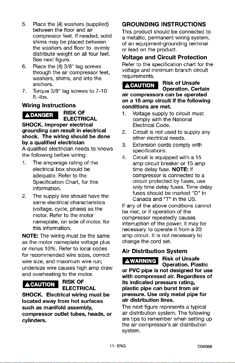
The next figure represents a typical
air distribution system. The following
are tips to remember when setting up
the air compressor's air distribution
system.
11_ENG D30088
Use pipe that is the same size as
the air tank outlet. Piping that is
too small will restrict the flow of
air.
If piping is over 100 feet long,
use the next larger size.
Bury underground lines below
the frost line and avoid pockets
where condensation can gather
and freeze. Apply pressure
before underground lines are
covered to make sure all pipe
joints are free of leaks.
A flexible coupling is
recommended to be installed
between the air discharge outlet
and main air distribution line to
allow for vibration.
A separate regulator is
recommended to control the air
pressure. Air pressure from the
tank is usually to high for
individual air driven tools.
FEEDER UN_S SLOPE
AIR FLOW _ WITH AIR FLOW
MAIN I_STRt BUTION A_R LINES
S_ope pipe in direction of air f_ow.
Water condensate flows a_ng
_botmm of pipe to drain legs,
preven_ng r; from entering feeder
_ines.
LUBRICATOR
DP_N _
TRAP
_MO_URE
SEPARATOR
AND TRAP
LEG
AIR DISCI-I,_G E /
VALVE
TYPICAL COMPRESSED
AIR DISTRIBUTION SYSTEM
DRAIN COCK
VALVE _
A_R
COMPRESSOR
D30088 12- ENG
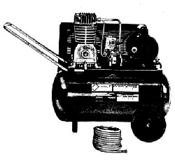
Know Your Air Compressor
READ THIS OWNER'S MANUAL AND SAFETY RULES BEFORE OPERATING
YOUR UNIT. Compare the illustrations with your unit to familiarize yourself with
the location of various controls and adjustments. Save this manual for future
reference.
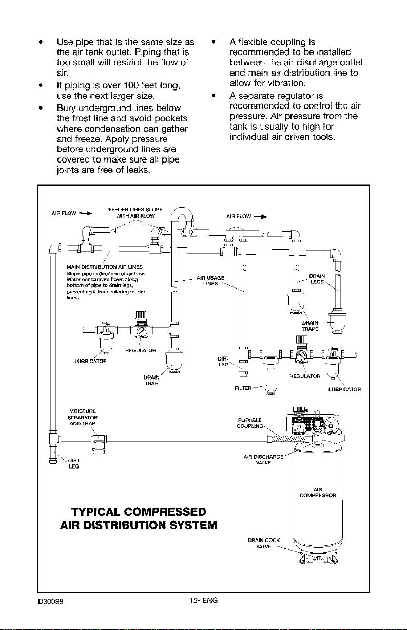
Description of Operation
Become familiar with these controls
before operating the unit.
Tank
Pressure Gauge
On/Auto/Off Switch: Turn this switch
ON to provide automatic power to the
pressure switch and OFF to remove
power at the end of each use.
Pressure Switch: The pressure
switch automatically starts the motor
when the air tank pressure drops
below the factory set "cut-in"
pressure. It stops the motor when the
air tank pressure reaches the factory
set "cut-out" pressure.
Safety Valve: If the pressure switch
does not shut off the air compressor
at its "cut-out" pressure setting, the
safety valve will protect against high
pressure by "popping out" at its
factory set pressure (slightly higher
than the pressure switch "cut-out"
setting).
13_ENG
Tank Pressure Gauge: The tank
pressure gauge indicates the reserve
air pressure in the tank.
Globe Valve: Opens and closes air
discharge valve. Turn knob counter-
clockwise to open and clockwise to
close.
Drain Valve: The drain valve is
located at the base of the air tank
and is used to drain condensation at
the end of each use.
Cooling System (not shown): This
compressor contains an advanced
design cooling system. At the heart of
this cooling system is an engineered
fan. It is perfectly normal for this fan
to blow air through the vent holes in
large amounts. You know that the
cooling system is working when air is
being expelled.
Air Compressor Pump (not shown):
Compresses air into the air tank.
Working air is not available until the
compressor has raised the air tank
pressure above that required at the
air outlet.
D30088
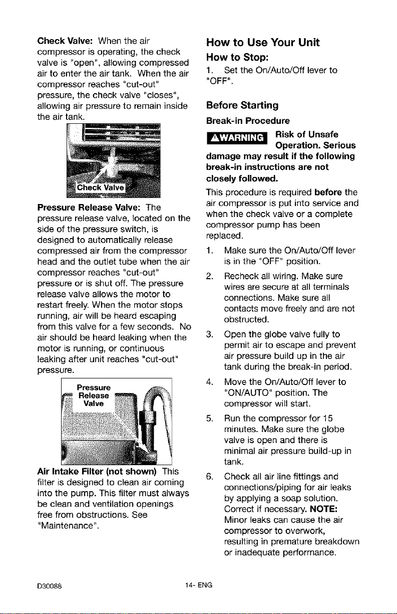
Check Valve: When the air
compressor is operating, the check
valve is "open", allowing compressed
air to enter the air tank. When the air
compressor reaches "cut-out"
pressure, the check valve "closes",
allowing air pressure to remain inside
the air tank.
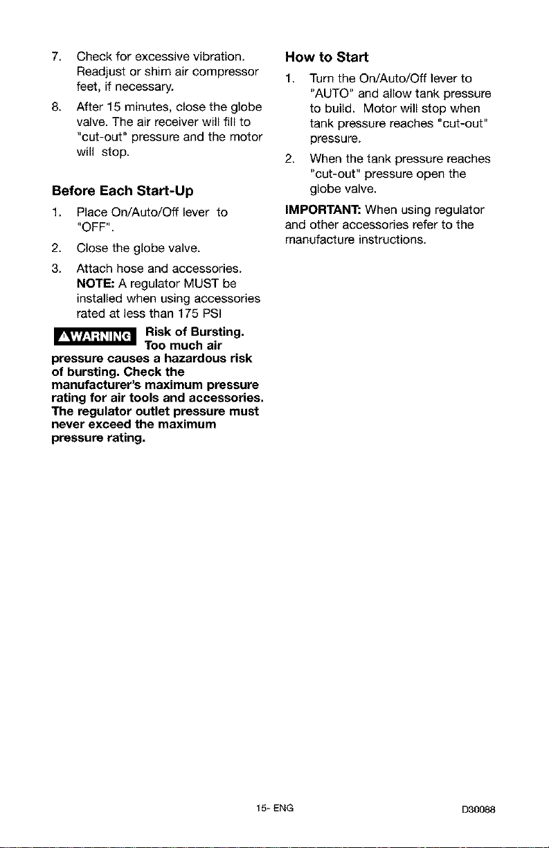
Pressure Release Valve: The
pressure release valve, located on the
side of the pressure switch, is
designed to automatically release
compressed air from the compressor
head and the outlet tube when the air
compressor reaches "cut-out"
pressure or is shut off. The pressure
release valve allows the motor to
restart freely. When the motor stops
running, air will be heard escaping
from this valve for a few seconds. No
air should be heard leaking when the
motor is running, or continuous
leaking after unit reaches "cut-out"
pressure.
Pressure
Release
Valve
Air Intake Filter (not shown) This
filter is designed to clean air coming
into the pump. This filter must always
be clean and ventilation openings
free from obstructions. See
"Maintenance".
How to Use Your Unit
How to Stop:
1. Set the On/Auto/Off leverto
"OFF".
Before Starting
Break-in Procedure
Risk of Unsafe
Operation. Serious
damage may result if the following
break-in instructions are not
closely followed.
This procedure is required before the
air compressor is put into service and
when the check valve or a complete
compressor pump has been
replaced.
1. Make sure the On/Auto/Off lever
is in the "OFF" position.
2. Recheck all wiring. Make sure
wires are secure at all terminals
connections. Make sure all
contacts move freely and are not
obstructed.
3. Open the globe valve fully to
permit air to escape and prevent
air pressure build up in the air
tank during the break-in period.
4. Move the On/Auto/Off lever to
"ON/AUTO" position. The
compressor will starL
5. Run the compressor for 15
minutes. Make sure the globe
valve is open and there is
minimal air pressure build-up in
tank.
6. Check all air line fittings and
connections/piping for air leaks
by applying a soap solution.
Correct if necessary. NOTE:
Minor leaks can cause the air
compressor to overwork,
resulting in premature breakdown
or inadequate performance.
D30088 14_ ENG
7. Check for excessive vibration.
Readjust or shim air compressor
feet, if necessary.
8. After 15 minutes, close the globe
valve. The air receiver will fill to
"cut-out" pressure and the motor
will stop.
Before Each Start-Up
1. Place On/Auto/Off lever to
"OFF".
2. Close the globe valve.
3. Attach hose and accessories.
NOTE: A regulator MUST be
installed when using accessories
rated at less than 175 PSI
Risk of Bursting.
Too much air
pressure causes a hazardous risk
of bursting, Check the
manufacturer's maximum pressure
rating for air tools and accessories,
The regulator outlet pressure must
never exceed the maximum
pressure rating.
How to Start
1. Turn the On/Auto/Off lever to
"AUTO" and allow tank pressure
to build. Motor will stop when
tank pressure reaches "cut-out"
pressure.
2. When the tank pressure reaches
"cut-out" pressure open the
globe valve.
IMPORTANT: When using regulator
and other accessories refer to the
manufacture instructions.
15_ ENG D30088

Customer Responsibilities
Check Safety Valve
Drain Tank
Air Filter
Inspect air lines and fittings
for leaks
Air compressor pump intake
and exhaust valves
Before Daily ol
after Every
aach each 40 Frequently
use use hours
1
Yearly
1- more frequent in dusty or humid conditions
Risk of Unsafe
Operation. Unit
cycles automatically when power is
on. When servicing, you may be
exposed to voltage sources,
compressed air, or moving parts.
Before servicing unit unplug or
disconnect electrical supply to the
air compressor, bleed tank of
pressure, and allow the air
compressor to cool.
To ensure efficient operation and
longer life of the air compressor, a
routine maintenance schedule should
be prepared and followed. The
following routine maintenance
schedule is geared to an unit in a
normal working environment
operating on a daily basis. If
necessary, the schedule should be
modified to suit the conditions under
which your compressor is used. The
modifications will depend upon the
hours of operation and the working
environment. Compressors in an
extremely dirty and/or hostile
environment will require a greater
frequency of all maintenance checks.
NOTE: See "Operation" section for
the location of controls.
To Check Safety Valve
Risk of Bursting. If
the safety valve
does not work properly, over-
pressurization may occur, causing
air tank rupture or an explosion.
1. Before starting compressor, pull
the ring on the safety valve to
make sure that the safety valve
operates freely. If the valve is
stuck or does not operate
smoothly, it must be replaced
with the same type of valve.
To Drain Tank
1. Set the On/Auto/Off lever to
"OFF" and disconnect electrical
supply.
2. Pull the regulator knob out and
turn clockwise to set the outlet
pressure to zero.
3. Remove the air tool or
accessory.
4.
Pull ring on safety valve allowing
air to bleed from the tank until
tank pressure is approximately
20 psi. Release safety valve ring.
5. Drain water from air tank by
opening drain valve (counter-
clockwise) on bottom of tank.
D30088 16_ ENG
I_ Risk of Bursting.
Water will
condense in the air tank. If not
drained, water will corrode and
weaken the air tank causing a risk
of air tank rupture.
6. After the water has been drained,
close the drain valve (clockwise).
The air compressor can now be
stored.
NOTE: If drain valve is plugged,
release all air pressure. The valve
can then be removed, cleaned, and
reinstalled.
Air Filter - Inspection and
Replacement
Risk of Burns.
Compressor head
and cylinder sleeve are very hot.
Do not touch. Allow compressor to
cool prior to servicing.
A dirty air filter will not allow the
compressor to operate at full
capacity. Keep the air filter clean at
all times.
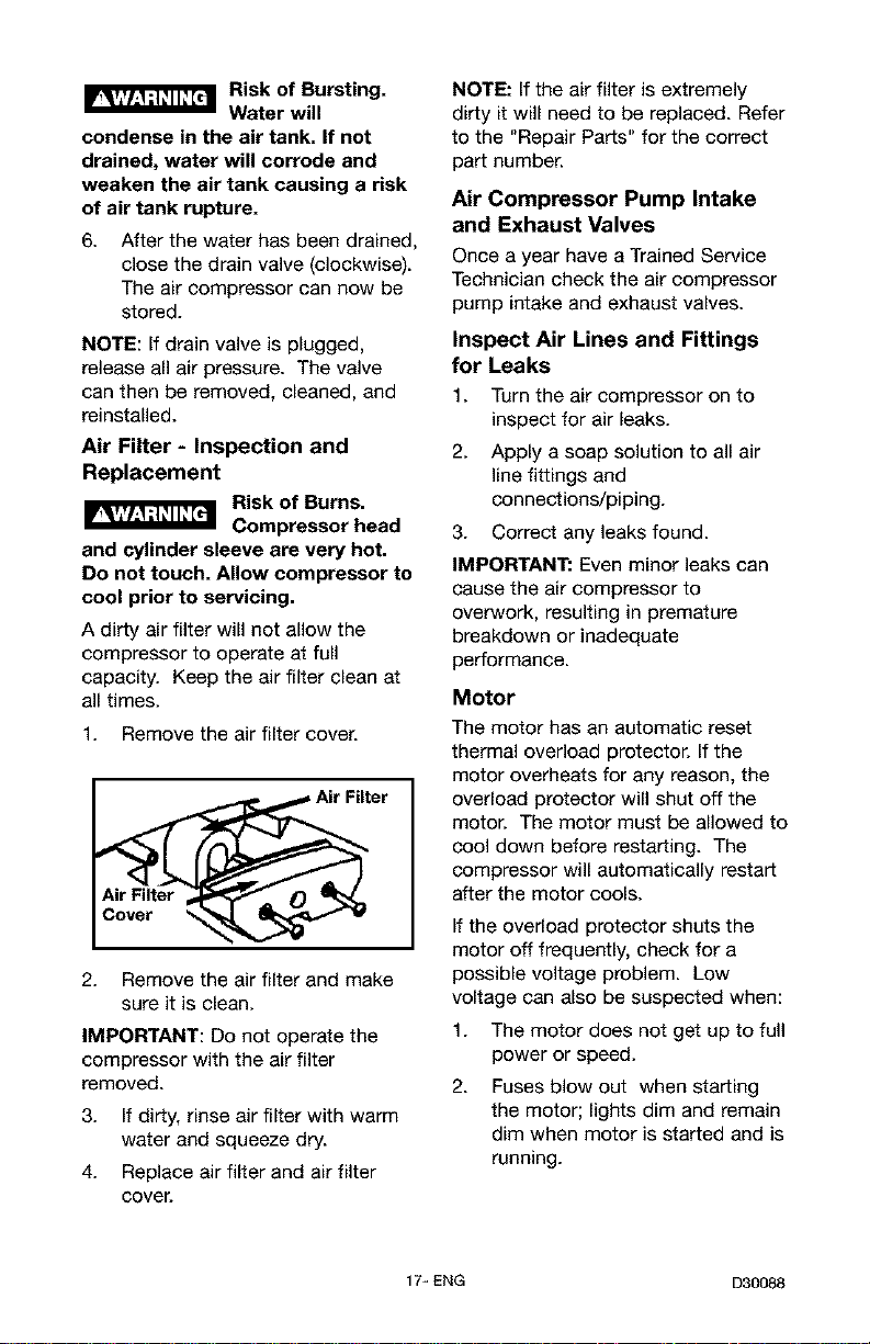
1. Remove the air filter cover.
Air Filter
Air Filter
2. Remove the air filter and make
sure it is clean.
IMPORTANT: Do not operate the
compressor with the air filter
removed.
3. If dirty, rinse air filter with warm
water and squeeze dry.
4. Replace air filter and air filter
cover.
NOTE: If the air filter is extremely
dirty it will need to be replaced. Refer
to the "Repair Parts" for the correct
part number.
Air Compressor Pump Intake
and Exhaust Valves
Once a year have a Trained Service
Technician check the air compressor
pump intake and exhaust valves.
Inspect Air Lines and Fittings
for Leaks
1. Turn the air compressor on to
inspect for air leaks.
2. Apply a soap solution to all air
line fittings and
connections/piping.
3. Correct any leaks found.
IMPORTANT: Even minor leaks can
cause the air compressor to
overwork, resulting in premature
breakdown or inadequate
performance.
MoOr
The motor has an automatic reset
thermal overload protector. If the
motor overheats for any reason, the
overload protector will shut off the
motor. The motor must be allowed to
cool down before restarting. The
compressor will automatically restart
after the motor cools.
if the overload protector shuts the
motor off frequently, check for a
possible voltage problem. Low
voltage can also be suspected when:
1. The motor does not get up to full
power or speed.
2. Fuses blow out when starting
the motor; lights dim and remain
dim when motor is started and is
running.
17_ ENG D30088
ALL MAINTENANCE AND REPAIR
OPERATIONS NOT LISTED MUST
BE PERFORMED BY TRAINED
SERVICE TECHNICIAN.
Risk of Unsafe
Operation. Unit
cycles automatically when power is
on. When servicing, you may be
exposed to voltage sources,
compressed air, or moving parts.
Before servicing unit unplug or
disconnect electrical supply to the
air compressor, bleed tank of
pressure, and allow the air
compressor to cool.
TO Replace or Clean Check
Valve
1. Release all air pressure from air
tank. See "To Drain Tank" in the
Maintenance section.
2. Set the On/Auto/Off lever to
"OFF" and disconnect electrical
supply
3. Using a phillips screwdriver
remove the air filter cover.
4. Remove the rear shrouds using
T-20 torx wrench.
5. Using an adjustable wrench
loosen outlet tube nut at air tank.
Carefully move outlet tube away
from check valve.
6. Using an adjustable wrench
loosen pressure relief tube nut at
air tank. Carefully move pressure
relief tube away from check
valve.
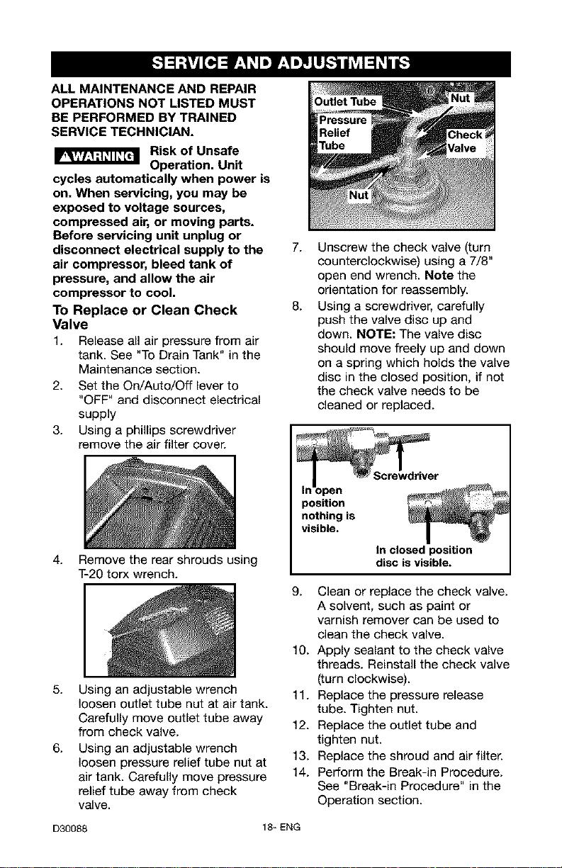
Outlet Tube
7.
8.
Unscrew the check valve (turn
counterclockwise) using a 7/8"
open end wrench. Note the
orientation for reassembly.
Using a screwdriver, carefully
push the valve disc up and
down. NOTE: The valve disc
should move freely up and down
on a spring which holds the valve
disc in the closed position, if not
the check valve needs to be
cleaned or replaced.
open
position
nothing is
visible.
tn closed position
disc is visible.
9. Clean or replace the check valve.
A solvent, such as paint or
varnish remover can be used to
clean the check valve.
10. Apply sealant to the check valve
threads. Reinstall the check valve
(turn clockwise).
11. Replace the pressure release
tube. Tighten nut.
12. Replace the outlet tube and
tighten nut.
13. Replace the shroud and air filter.
14. Perform the Break-in Procedure.
See "Break-in Procedure" in the
Operation section.
D30088 18_ ENG
Before you store the air compressor,
make sure you do the following:
1. Review the "Maintenance"
section on the preceding pages
and perform scheduled
maintenance as necessary.
2. Set the On/Auto/Off lever to
"OFF" and disconnect electrical
supply
3. Close the globe valve.
4. Remove the air tool or accessory.
5. Open the globe valve and allow
the air to slowly bleed from the
air tank until tank pressure is
approximately 20 psi.
6. Drain water from air tank by
opening drain valve (counter-
clockwise) on bottom of tank.
Risk of Bursting.
Water will
condense in the air tank. If not
drained, water will corrode and
weaken the air tank causing a risk
of air tank rupture.
7. After the water has been drained,
close the drain or drain valve.
NOTE: If drain valve is plugged,
release all air pressure. The valve
can then be removed, cleaned, then
reinstalled.
8. Protect the air hose from
damage (such as being stepped
on or run over).
19_ ENG D30088
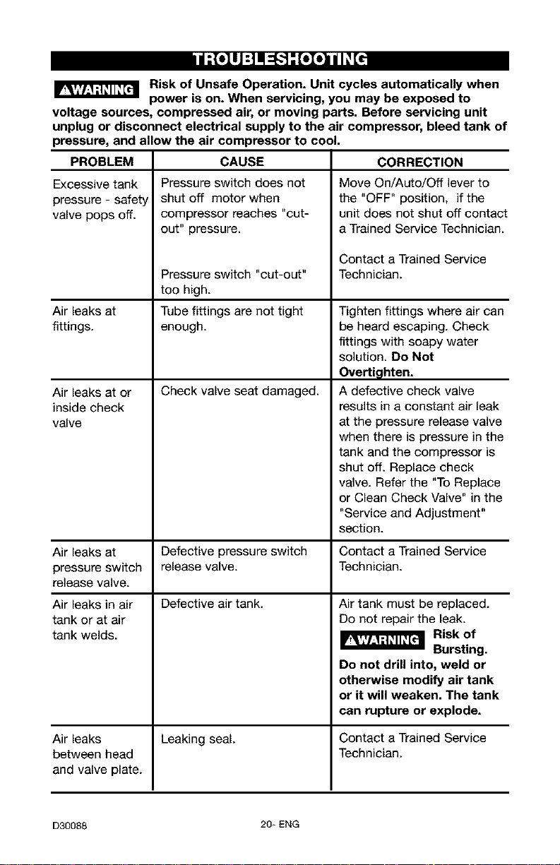
d:{ollJ :] il ::F,."]-"[oIo]l III_[I
Risk of Unsafe Operation. Unit cycles automatically when
power is on. When servicing, you may be exposed to
voltage sources, compressed air, or moving parts. Before servicing unit
unplug or disconnect electrical supply to the air compressor, bleed tank of
pressure, and allow the air compressor to cool.
PROBLEM CORRECTION
Excessive tank
pressure - safet
valve pops off.
Air leaks at
fittings.
Air leaks at or
inside check
valve
CAUSE
Pressure switch does not
shut off motor when
compressor reaches "cut-
out" pressure.
Pressure switch "cut-out"
too high.
Tube fittings are not tight
enough.
Check valve seat damaged.
Move On/Auto/Off lever to
the "OFF" position, if the
unit does not shut off contact
a Trained Service Technician.
Contact a Trained Service
Technician.
Tighten fittings where air can
be heard escaping. Check
fittings with soapy water
solution. Do Not
Overti_hten.
A defective check valve
results in a constant air leak
at the pressure release valve
when there is pressure in the
tank and the compressor is
shut off. Replace check
valve. Refer the "To Replace
or Clean Check Valve" in the
"Service and Adjustment"
section.
Air leaks at Defective pressure switch Contact a Trained Service
pressure switch release valve. Technician.
release valve.
Defective air tank.
Air leaks in air
tank or at air
tank welds.
Air tank must be replaced.
Do not repair the leak.
Risk of
Bursting.
Do not drill into, weld or
otherwise modify air tank
or it will weaken. The tank
can rupture or explode.
Air leaks Leaking seal. Contact a Trained Service
between head Technician.
and valve plate.
D30088 20_ENG
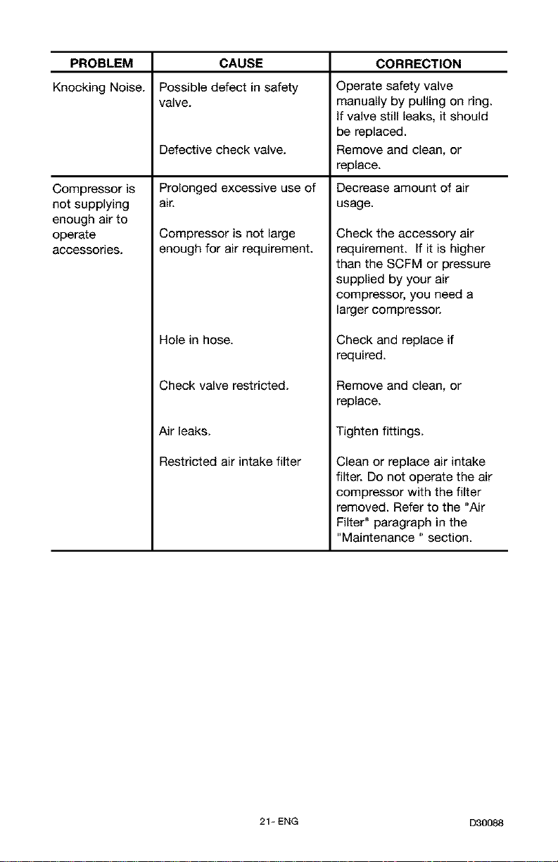
PROBLEM CAUSE CORRECTION
Knocking Noise. Possible defect in safety Operate safety valve
valve, manually by pulling on ring.
If valve still leaks, it should
be replaced.
Defective check valve. Remove and clean, or
replace.
Prolonged excessive use of Decrease amount of air
air. usage.
Compressor is
not supplying
enough air to
operate
accessories.
Compressor is not large
enough for air requirement.
Hole in hose.
Check valve restricted.
Air leaks.
Restricted air intake filter
Check the accessory air
requirement. If it is higher
than the SCFM or pressure
supplied by your air
compressor, you need a
larger compressor.
Check and replace if
required.
Removeand clean, or
replace.
Tighten fittings.
Clean or replace air intake
filter. Do not operate the air
compressor with the filter
removed. Refer to the "Air
Filter" paragraph in the
"Maintenance " section.
21_ENG D30088

PROBLEM
Motor will not
run.
CAUSE
Motor overload protection
switch has tripped
Tank pressure exceeds
pressure switch "cut-in"
pressure.
Extension cord is wrong
length or gauge.
Check valve stuck open.
Loose electrical connections.
Possible defective motor or
starting capacitor.
Paint spray on internal motor
parts.
Pressure release valve on
3ressure switch has not
unloaded head pressure.
Fuse blown, circuit breaker
tripped.
CORRECTION
Let motor cool off and
overload switch will
automatically reset.
Motor will start automatically
when tank pressure drops
below "cut-in" pressure of
)ressure switch.
Check for proper gauge wire
and cord length.
Remove and clean, or
replace.
Check wiring connection
inside pressure switch and
terminal box area.
Have checked by a Trained
Service Technician.
Have checked by a Trained
Service Technician. Do not
operate the compressor in
the paint spray area. See
flammable vapor warning.
Bleed the line by pushing the
lever on the pressure switch
to the "off" position; if the
valve does not open, replace
switch.
1. Check fuse box for blown
fuse and replace as
necessary. Reset circuit
breaker. Do not use a fuse
or circuit breaker with
higher rating than that
specified for your particular
branch circuit.
2. Check for proper fuse. You
should use a time delay
fuse.
3. Check for low voltage
conditions and/or proper
extension cord.
4. Disconnect the other
electrical appliances from
circuit or operate the
compressor on its own
branch circuit.
D30088 22- ENG
23-ENG D30088
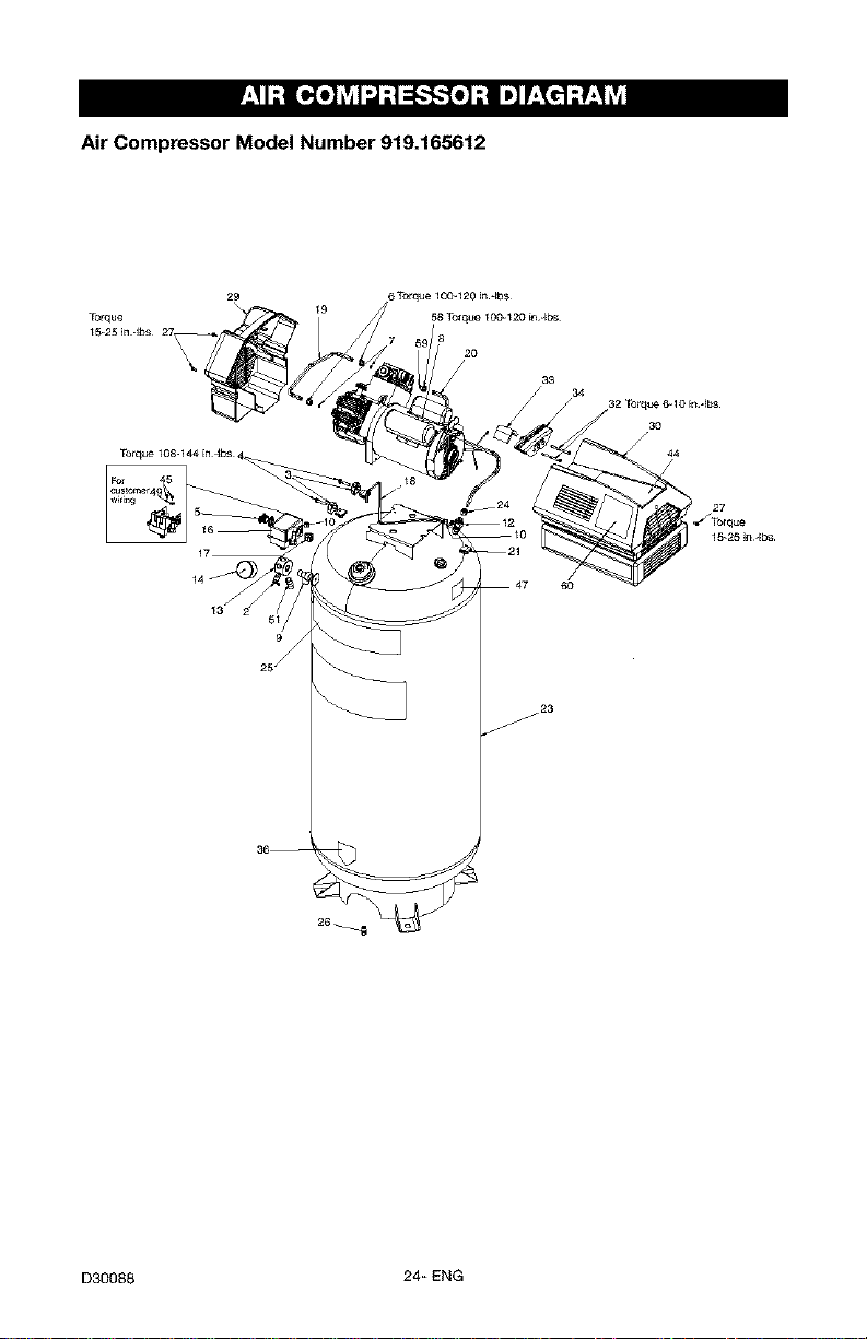
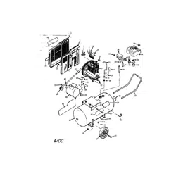
Air Compressor Model Number 919.165612
j23
J
D30088 24+ ENG
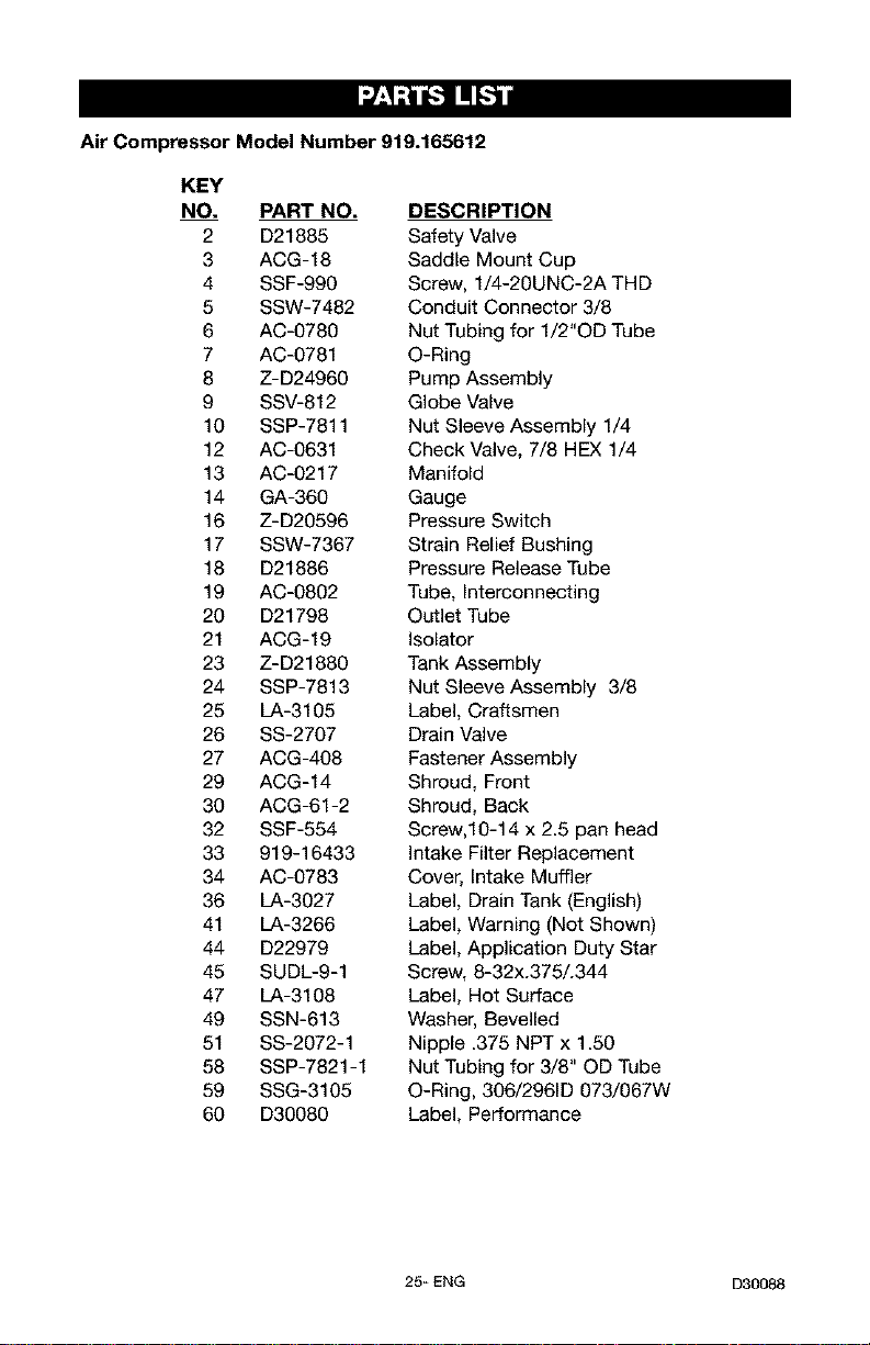
Air Compressor Model Number 919.165612
KEY
NO. PART NO.
2 D21885
3 ACG-18
4 SSF-990
5 SSW-7482
6 AC-0780
7 AC-0781
8 Z-D24960
9 SSV-812
10 SSP-7811
12 AC-0631
13 AC-0217
14 GA-360
16 Z-D20596
17 SSW-7367
18 D21886
19 AC-0802
20 D21798
21 ACG-19
23 Z-D21880
24 SSP-7813
25 LA-3105
26 SS-2707
27 ACG-408
29 ACG-14
30 ACG-61-2
32 SSF-554
33 919-16433
34 AC-0783
36 LA-3027
41 LA-3266
44 D22979
45 SUDL-9-1
47 LA-3108
49 SSN-613
51 SS-2072-1
58 SSP-7821-1
59 SSG-3105
60 D30080
DESCRIPTION
Safety Valve
Saddle Mount Cup
Screw, 1/4-20UNC-2A THD
Conduit Connector 3/8
Nut Tubing for 1/2"OD Tube
O-Ring
Pump Assembly
Globe Valve
Nut Sleeve Assembly 1/4
Check Valve, 7/8 HEX 1/4
Manifold
Gauge
Pressure Switch
Strain Relief Bushing
Pressure Release Tube
Tube, Interconnecting
Outlet Tube
Isolator
Tank Assembly
Nut Sleeve Assembly 3/8
Label, Craftsmen
Drain Valve
Fastener Assembly
Shroud, Front
Shroud, Back
Screw,10-14 x 2.5 pan head
Intake Filter Replacement
Cover, Intake Muffler
Label, Drain Tank (English)
Label, Warning (Not Shown)
Label, Application Duty Star
Screw, 8-32x.375/.344
Label, Hot Surface
Washer, Bevelled
Nipple .375 NPT x 1.50
Nut Tubing for 3/8" OD Tube
O-Ring, 306/2961D 073/067W
Label, Performance
25_ ENG D30088
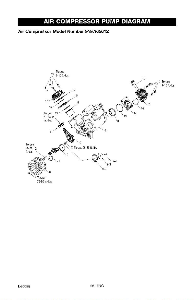
Air Compressor Model Number 919.165612
Torque
+ 7-10ft 4bs+
+9Torque
7-10ft.-Ibs
Torque
51-6311
in.-Ibs
\9-2
\17
\15
Torque
25-35 2
25-35 ft.-Ibs
\9 ",.
\7 Torque
75-90in+-Ibs
D30088 26+ ENG
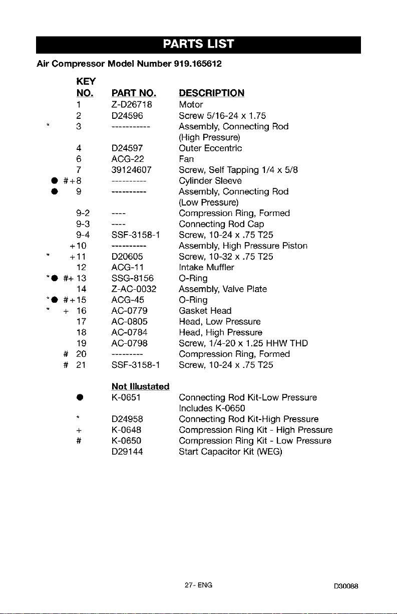
Air Compressor Model Number 919.165612
KEY
NO. PART NO.
1 Z-D26718
2 D24596
3
4 D24597
6 ACG-22
7 39124607
• #+8
• 9
9-2 ....
9-3 ....
9-4 SSF-3158-1
+10
+ 11 D20605
12 ACG-11
*• #+ 13 SSG-8156
14 Z-AC-0032
*• #+15 ACG-45
+ 16 AC-0779
17 AC-0805
18 AC-0784
19 AC-0798
# 20
# 21 SSF-3158-1
+
#
DESCRIPTION
Motor
Screw 5/16-24 x 1.75
Assembly, Connecting Rod
(High Pressure)
Outer Eccentric
Fan
Screw, Self Tapping 1/4 x 5/8
Cylinder Sleeve
Assembly, Connecting Rod
(Low Pressure)
Compression Ring, Formed
Connecting Rod Cap
Screw, 10-24 x .75 T25
Assembly, High Pressure Piston
Screw, 10-32 x .75 T25
Intake Muffler
O-Ring
Assembly, Valve Plate
O-Ring
Gasket Head
Head, Low Pressure
Head, High Pressure
Screw, 1/4-20 x 1.25 HHW THD
Compression Ring, Formed
Screw, 10-24 x .75 T25
Not Illustated
K-0651
D24958
K-0648
K-0650
D29144
Connecting Rod Kit-Low Pressure
Includes K-0650
Connecting Rod Kit-High Pressure
Compression Ring Kit - High Pressure
Compression Ring Kit - Low Pressure
Start Capacitor Kit (WEG)
27_ ENG D30088
GARANT|A 28
CUADRO DE ESPECIFICACIONES ...................................... 29
DEFINICIONES DE NORMAS DE SEGURIDAD ............................. 29
IMPORTANTES INSTRUCCIONES DE SEGURIDAD ...................... 29-34
GLOSARIO .......................................................... 35
ACCESORIOS ....................................................... 35
CICLO DE SERVICIO .................................................. 35
ENSAMBLADO ....................................................... 36
INSTALACION ..................................................... 36-38
OPERACION ...................................................... 39-41
MANTENIMIENTO ................................................. 42-43
SERVICIOS Y REGULACIONES ......................................... 44
ALMACENAJE ....................................................... 45
GU(A DE DIAGNOSTICO DE PROBLEMAS ............................. 46-48
NOTES/NOTAS .................................................... 49-50
CONTRATOS DE PROTECCION PARA REPARACIONES ..................... 51
LISTA DE PARTES ................................................. 24-27
COMO SOLICITAR PIEZAS PARA REPARACION .................... contratapa
GARANT|A TOTAL DE UN AI_IO DEL COMPRESOR DE AIRE
Si este compresor de aire Craftsman fallase debido a defectos de materiales
o de fabricaci6n dentro del aSo de su fecha de compra, Sears, a su opei6n, Io
reparar& o reemplazar& sin eosto alguno. Comuniquese con el Centro de
Servicio Sears m&s cercano (1-800-4-MY-HOME) para coordinar su
reparaci6n, o devuelva el compresor de aire al lugar donde Io compr6 para
que Io cambien.
Si este compresor de aire se usase con fines comerciales o para alquiler, esta
garantia se aplica s61o durante los primeros noventa dias a partir de su fecha
de compra.
Esta garantia le otorga derechos especfficos y usted podrfa tener otros
derechos que varian de un estado a otto.
Sears, Roebuck and Co., Dept. 817WA, Hoffman Estates, IL 60179
D30088 28- SP
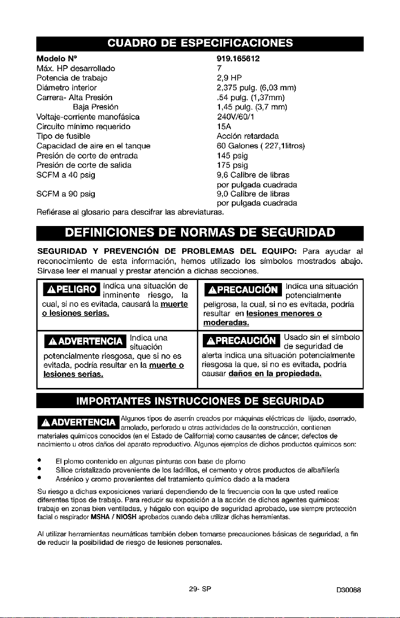
Modelo N°
Max. HP desarrollado
Potencia de trabajo
Di&metro interior
Carrera- Alte Presi6n
Beja Presi6n
Voltaje-corriente manof&sica
Circuito mfnimo requerido
Tipo de fusible
Capacidad de sire en el tanque
Presi6n de corte de entrada
Presi6n de corte de salida
SCFM a 40 psig
SCFM a 90 psig
919.165612
7
2,9 HP
2,375 pulg. (6,03 mm)
.54 pulg. (1,37mm)
1,45 pulg. (3,7 mm)
240V/60/1
15A
Accion retardada
60 Galones (227,111tros)
145 psig
175 psig
9,6 Calibre de libras
por pulgada cuadrada
9,0 Calibre de libras
por pulgada cuadrada
Refi6rase al glosario pars descifrar las abreviaturas.
SEGURIDAD Y PREVENCION DE PROBLEMAS DEL EQUIPO: Para ayudar al
reconocimiento de esta informaci6n, hemos utilizedo los simbolos mostrados abajo.
Sirvase leer el manual y prestar atenci6n a dichas secciones.
_ Indicauna situaci6nde
inminente la
riesgo,
cual, si no es evitada, causar& la muerte
o lesionee series.
potencialmente riesgosa, que si no es
evitada, podda resultar en la muerte o
lesiones serias,
_ Indica una situaci6n
potencialmente
peligrosa, la cual, si no es evitada, podria
resultar en lesiones menores o
moderades.
_ Usado sin el simbolo
de seguridad de
alerts indica una situacion potencialmente
riesgosa la que, si no es evitada, podria
causar da_os en le propiedade.
_ AIgunos tipos de aserr[n cresdos pot m&quinas electricas de Iijado, sserrado,
_motsdo, perforado u otras actividades de Is construcci6n, contienen
materiales qu_micos conocidos (en el Estado de California) como causantes de c&ncer, defectos de
nacimiento u otros d_os del aparato reproductivo. A_gunos ejemplos de dichos productos quimicos son:
El plomo contenido en algunas pinturas con base de pIomo
Silice cristalizado proveniente de los ladrillos, el cemento y otros productos de albaSilerla
• Ars6nioo y oromo provenientes del tr_tamiento qulmico dado a la readers
Su nesgo a dichas exposiciones variar& dependiendo de la frecuencia con ta que usted realice
diferentes tipos de trabajo. Pars reducir su exposiciSn a la acciSn de dichos agentes qulmicos:
trabaje en zonas bien ventilada& y h&galo con equipo de seguridad aprobado, use siempre protecci6n
facial o respirader MSHA / NIOSH aprobades cuande deba utilizar dichas herrarnientas.
AI utilizar herramientas neum&tioas tarnbi_n deben tomarse precauciones b&sicas de seguridad, a fin
de reducir la posibilidad de riesgo de lesiones personales.
29* SP D30088
GUARDE ESTAS INSTRUCCIONES
La operaci6n o el mantenimiento inadecuados de este producto podrian ocasionar
serias lesiones y dafios a la propiedad. Lea y comprenda todas las advertencias e
instrucciones de funcionamiento antes de utilizar este equipo.
',,1=ll [_ ;{q
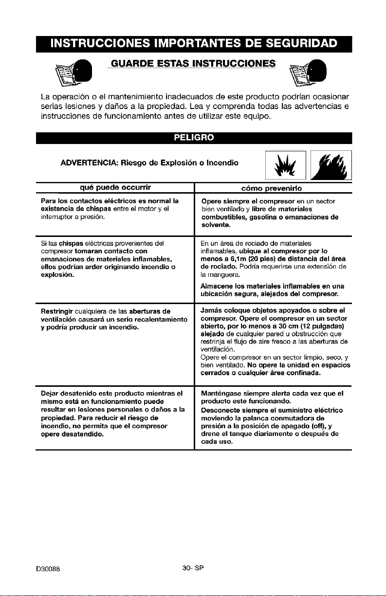
ADVERTENCIA: Riesgo de Explosi6n o Incendio
qud puede occurrir c6mo prevenido
Para los contactos el_ctricos es normal la Opere siempre el compresor en un sector
existencia de chispas entre el motor y el bien ventilado y libre de materiales
interruptor a presi6n, combustibles, gasolina o emanaciones de
solvente.
Si las chispas electricas provenientes del En un _rea de rociado de materiaIes
eompresor tomaran contacto con inflamables, ubique al compresor pot Io
emanaciones de materiales inflamables, menos a 6,1m (20 pies) de distancia del _rea
ellos podrlan arder originando incendio o de rociado. Podria requerirse una extensi6n de
explosi6n= la manguera.
Almacene los materiales inflamables en una
ubicacibn segura, alejados del compresor.
Restringir eualquiera de las aberturas de
ventilacibn causar_i un serio recalentamiento
y podrla producir un incendio.
Dejar desatenido este producto mientras el
mismo estd en funcionamiento puede
resultar en lesiones personales o da_os a la
propiedad. Para reducir el riesgo de
incendio, no permita que el compresor
opere desatendido.
Jam_is coloque objetos apoyados o sobre el
compresor. Opere el compresor en un sector
abierto, pot Io menos a 30 cm (12 pulgadas)
alejado de cuaIquier pared u obstrucci6n que
restrinja el flujo de aire fresco alas aberturas de
ventilaci6n.
Opere el compresor en un sector limpio, seco, y
bien ventilado. No opere la unidad en espacios
cerrados o cualquier _irea confinada.
Mantdngase siempre alerta cada vez que el
producto este funcionando.
Desconecte siempre el suministro el_ctrico
moviendo la palanca conmutadora de
presibn a la posicibn de apagado (off), y
drene el tanque diariamente o despu_s de
cada uso.
D30088 30- SP
'.,1=ll [_1t.{q
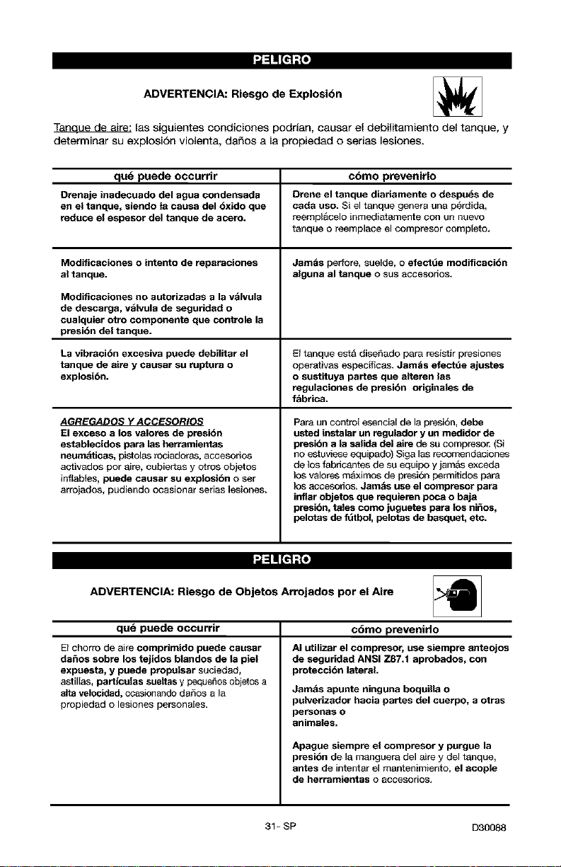
ADVERTENCIA: Riesgo de Explosibn
T_ las siguientes condiciones podrian, causar el debilitamiento del tanque, y
determinar su explosiSn violenta, daSos a la propiedad o serias lesiones.
qu_ puede occurrir c6mo prevenirlo
Drenaje inadecuado del agua condensada Drene el tenque diariamente o despu_s de
en el tanque, siendo la causa del 6xido que cada uso. Si el tanque genera una p_rdida,
reduce el espesor del tanque de acero, reempl&celo inmediatamente con un nuevo
tanque o reemplace el compresor complete,
Modificaciones o intento de reparaciones Jam_s perfore, suelde, o efectt3e modificaci6n
al tanque, alguna al tanque o sus accesorios,
Modificaciones no autorizadas a la v_ivula
de descarga, v&lvula de seguridad o
cualquier otro componente que controle la
presi6n del tanque.
La vibracibn excesiva puede debilitar el El tanque estA dise_ado para resistir presiones
tanque de aire y causar su ruptura o operativas especificas, Jamds efectde ajustes
explosi6n, o sust_tuya partes que alteren las
regulaciones de presi6n originales de
f_brica.
AGREGADOS Y ACCESORIOS
El exceso a los valores de presi6n
establecidos para las he_amientes
neum#ticas, pistolas rociadoras, accesorios
activados pot aire, cubiertas y otros objetos
infiabtes, puede causar su explosibn o set
arrojados, pudiendo ocasionar serias lesiones,
Para un control esencial de la presibn, debe
usted instalar un regulador y un medidor de
presi6n a la salida del aire de su compresor. (Si
no estuviese equipade) Siga las recomendaciones
de los fabdcantes de su equipo y jam&s exceda
los valores m&xiIT_S de presibn permitidos pare
los accesodos, Jam_s use el c-ompresor para
inflar objetos que requieren poca o baja
presibn, tales como juguetes para los niSos,
pelotas de _tbol, pelotas de basquet, etc.
'.,1=ll [_1t.{q
ADVERTENCIA: Riesgo de Objetos Arrojados pot el Aire
qu_ puede occutrit c6mo ptevenirlo
E_chorro de aire comprimido puede causar
da_os sobre los tejidos blandos de la piel
expueste, y puede propulsar sueiedad,
astillas, partlculas suettas y pequeSos objetos a
alta velocidad, ccasionando da_os a la
propiedad o lesiones personales,
AI utilizar el compresor, use siempre anteojos
de seguridad ANSI 7-87.1 aprobados, con
protecci6n lateral.
Jam_is apunte ninguna boquilla o
pulverizador hacia partes del cuerpo, a otras
personas O
animales=
Apague siempre el eompresor y purgue la
presibn de la manguera del aire y del tanque,
antes de inte_ar el mantenimiento_ el acople
de herramientas o 8ccesorios,
31 _ SP D30088
•,,l::1nnl[_1r,{q
ADVERTENCIA: Riesgo de Descatga Eldctrica _/F
qud puede occurrir cbmo prevenirlo
Su compresor de aire estA accionado pc# Jam_s opere el compresor a la intemperie
electricidad, Como cua_quier otto dispositivo cuando est& Iloviendo o en condiciones de
el_ctrico imputsado et6ctricamente, si no se Io humedad,
utiliza adecuadamente, podria causarle una Nunca opere el compresor sin sus defensas o
descarga el_ctrica, sus cubiertas removidas o da_adas.
Las reparaciones intentadas pot personal Cualqu+er conexibn el_ctrica o _eparaci6n
no calificado podrian ocasionar serias requerida pot este producto debe ser
$esiones o la muerte por electrocuci6n, efectuada pot personal autorizado de los
servicentros de acuerdo a los c6d+gos
el_ctricos nacionales y locales.
CONEXI(_N A TIERRA: Dejar de proveer una Asegt_rese que el circuito el_ctrico al cual
adecuada cormxibn a tierra a este producto est& conectado el compresor, suministra
pedria ccasionar lesiones serias o la muerte apropiada conexibn a tierra, tensi6n correcta
por electrocuci6n= Vet instrucciones para la y una adecuada protecci6n de fusibles.
puesta a tierra.
p,.]:4unlIt1:To]
ADVERTENCIA: Riesgo de Inhalaci6n
qud puede occurrir cbmo prevenirlo
E_aire comprimido proveniente del compresor
no es sano para respirar. El chorro de aire
puede contener mon6xido de carbono,
vapores t6xicos o partlculas sblidas
provenie_es del tanque. La inhalaci6n de
dichos contaminantes peede Uegar a causar
serias lesiones o la muerte=
El tociado de materiates tales como pintura,
solventes, removedores de pintura,
insecticidas, mata hierbas, contienen
emanaciones da_inas y venenosas,
E_aire obtenido directamente del compresor
am_is deberd ser utilizado para proveer aim
_ara consumo humano. Para poder utilizar el
aire producido por este compresor y hacerlo
respirable, deber_in instalarse un filtro
adecuado y un equipe de seguridad
intercalado= Los filtros intercalados tanto como
el equipo de seguridad utilizado en conjunto
con el compresor, deber_n ser capaces de
}rocesar el tratamiento del aire de acuerdo a
todos los cbdigos locales y federales, previo
al consumo humano.
Trabaje en un &rea con buena ventilacibn
cruzada. Lea y siga las instrucciones de
seguridad provistas en el r6tulo o en los datos
de las hojas de seguridad del material que est_
}ulverizando. Use el respirador aprobado
NIOSH/MSHA designado para utilizarse con su
8plicaciSn especffica,
D30088 32_SP
_=ll[_r,{w
ADVERTENCIA: Riesgo de Quemaduras
qu_ puede occurrir
Tooar el metal expuesto tal como el cabezsI
del compresor o los tubos de salida del
escape, puede ocasionarle serias
quemaduras.
cbmo prevenirlo
Jam_is toque partes de metal expuestas en el
compresor durante o inmedistamente despu_s
de la operaci6n, el compresor permanecer_
caliente pot varios minutos luego de la
operaci6n.
No Io cubra con fundas protectoras o intente el
mantenimiento hasta que la unidad haya
alcanzado su enfriamiento.
_=ll[_r,{w
ADVERTENCIA: Riesgo de Partes Mbviles
que puede occurrir cbmo prevenirlo
Partes movibles tales come Ia pole& el Nunca opere el compresor sin sus defensas
volante y la correa podrlan ser la causa de o sus cubiertas removidas o da_adas.
serias lesiones si elias entraran en contacto
con usted o sus ropas.
Intentar operar el compresor con sus Cualquier reparaci6n requerida pot este
partes da_adas o faitantes, o la reparacibn producto debe ser efectuada pot personal
del compresor con sus protecciones autorizado de los servicentros.
removidas, puede exponerlo a usted a
partes movibles, que podrlan resultar en
lesiones serias=
#=ll [_ r,{,,
ADVERTENCIA: Riesgo de Caida _
qu_ Duede occurrir cbmo orevenirlo
Un compresor port&til puede caerse de la
mesa, el banco de trabs_o o del techo da_ando
al compresor y pudiendo resultar en serias
lesiones o la muerte del operador=
Opere siempre el compresor en una posici6n
estable y segura a fin de prevenir el
movimiento accidental de la unidad. Jam_s
opere el compresor sobre un techo u otra
posicibn elevada. Utilice mangueras
adicionales de aire para alcanzar posiciones
altas.
33- SP D30088
',1=1
Familiariceee con los siguientes t_rminos,
antes de operar la unidad:
OFM: (Cubic feet per minute) Pies cQbicee
por minuto.
SCFM: (Stardard cubic feet per minute)
Pies cebicos est&ndar por minuto; ana
unidad de medida que permite medir la
cantidad de entrega de aire.
PSIG: (Pound per square inch) Libras pot
pulgada cuadrad&
ASME: American Society of Mechanical
Engineers (Seeiedad Americana de
Ingenieree Mec&nicos); heeho probado
inspeccionado y registrado an
cumplimiento de los est&ndares de la
ASME.
Obdigo de eettifieacibn: Los productos
que usan una o m&s de lee siguiantee
marcas: UL, CUL, ETL, CETL, hart sido
evaluados por OSHA, laboratoriee
indepandientes certificados an seguridad,
y ret_nan los est&ndaree suscdptos por los
laboratoriee dedicados a la certifieeei6n
de la seguridad.
Presi6n minima de torte: Cuando el
motor est& apagado, la presion del tanque
de aire baja a medida que usted coatint_a
usando su eeceeerio. Cuando la presi6n
del tanque baja al valor fijado an f&brica
como punto bajo, el motor volver& a
arrancar autom&ticamante. La presion
baja a la cual el motor arranca
autom&ticamente, se llama presi6n
"minima de corte".
Presi6n mbxima de corte: Cuando un
compresor de aire se enciende y
comianza a fancionar, la presi6n de aire an
el tanque comienza a aumantar. Aumanta
hasta un valor de presi6n alto fijado en
f&brica antes de que el motor
autom&ticamente se apague protegiendo
a su tanque de aire de presiones m&s
altas que su capacidad. La presi6n alta a
la cual el motor se apaga se llama presi6n
"m&xima de corte".
Ramal: Circuito el6ctrico que transporta
electricidad desde el panel de control
hasta el tomacorriante.
Los accesorios y las herramientas se
encueatran disponibles a traves del
cat&logo actual de Herramientas el6ctricas
y de mano, o la linea completa en los
comercios Sears.
Accesorios
Filtro en linea
Entrada de aire a neum&ticos
Juegos de conectores r&pidos
(varios tama£1os)
Reguladores de presi6n de aire
Lubricadores de niebla de aceite
Manguera de aire:
1/4 po, 3/8 po o 1/2 po D.L en
varias medidas
Refi_rase al grafico de selecci6n ubicado
eebre la unidad, para elegir el tipo de
herramienta que esta unidad es capaz de
hacer funcionar.
[o,][_o] I'_]:4b_o,] [o]
Esta bomba compreeera de aire es capaz
de fancionar continuamante, sin embargo
para prolongar la vida 6til de su
compresor de aire se recomieada
mantener un cielo promedio de servicio
que oscile entre el 50% y el 75%; ello
significa que la bomba compresora no
deberia trabajar m&s de 30 a 45 minutos
pot hora.
35 - SP D30088

Contenido de la Caja
1 - Compresor de aire
1 - Bolsa de piezas conteniendo Io
siguiente:
1 - Manual del operador
1 - Manual de piezas
4 - Arandelas de 5/8 po
Herramientas necesarias para el
ensamble
1 - Ilavede tuboo de boca de 9/16 po
Desembalaje
1. Extraiga todo el emba]aje
Lasegura. Podra ser necesario
apuntalar o soportar un lado del equipo
al extraer la plataforma, porque el
compresor de aire tendera a inclinarse,
2. Extraiga y descarte los (4) tomillos y
arandelas que sujatan el compresor a
la plataforma.
3. Con la ayuda de otra persona,
remueva cuidadosamente el
compresor de aire de su plataforma y
coloquelo sobre una plataforma
nivelada.
COMO PREPARAR LA UNIDAD
Ubicacibn del comp_sor de aire
Instale el compresor de aire en una
zona limpia, seca y bien ventilada.
Instale el compresor de aire a aria
distancia no menor de 12 po (30 cm)
de la pared u otras obstrucciones
que pudiesen interferir con el flujo del
aire.
Instale el compresor de aire Io m&s
oerca posible del sitio de
alimentaci6n electrica, a fin de evitar
el uso de largas extensiones de
cableado electrico. NOTA: Las
extensiones electricas demasiado
largas pueden causar una caida de
tension perjadicial para la
alimentaci6n del motor.
El filtro de aire debe mantenerse libre
de obstrucciones que pudiesen
reducir el flujo del aire al compresor.
Anclaje del compresor de aire
_ Ri_go de
_raci6n
Lasegura. La vibraci6n excesiva puede
debilitar al tanque de aire y causar su
explosibn, El compresor debe estar
montado adecuadamente.
El compresor de aire DEBE estar
abulonado a una superficie s61ida y
nivelada.
D30088
Elementos necesarios:
1,
2,
3,
4 - Tarugos para anclajes en
cemento
4 - Tornillos tirafondo de 3/8 po
capaces de Ilenar los
tarugos para anclaje en
cemento (no provistos)
4 - Arandelas 5/8 po (en la bolsa de
piezas)
Cu_as
(en caso de set necesario)
Instale el compresor de aire sobre
una super[icie solida y nivelada.
Marque 18superficie utilizando como
plantilla, los orificios existentes en el
compresor de aire.
Perfore la superficie, a fin de penetrar
los tarugos para
anclaje en el cemento. Coloque los
tarugos en el cemento.
Tomillo
Arandela de tirafondo de
5/8 po "3/8po (no
(suministrada) suministrado)
Linea de superficie
Curia debajo de
la arandela (no Tarugos para anclaje
suministrada) en cemento (no
suministrados)
36- SP
4 Haga coincidir la alineacion de los
orificios de la superfieie, con el de Ins
patas del compresor de aire.
5. Coloque las (4) arandelas
(suministradas) entre el piso y las
patas del compresor. Si fuese
necesario, pueden colocarse cu£_as
solidas entre las arandelas y el piso
a fin de distribuir en forma pareja el
peso sobre Ins cuatro patas. Vea la
figura siguiente.
6. Coloque los (4) tomillos tirafondo de
3/8 po a traves de Ins patas del
compresor de aire, de Ins arandelas y
cutlas, hasta Ilegar a los tarugos de
anclaje.
7. Apliqae an torque de 7-10 ft-lb, sobre
los tornillos tirafondo de 3/8 po.
Instrucciones para la conexi6n
el_ctrica
RIESGO DE CHOQUE
ELECTRICO. Una
conexibn a tierra inadecuada puede
ocasionar electrocuci6n. Las conexiones
eldetricae deben eer efectuadas per un
electricista calificado.
Antes de efectaar Ins conexiones, an
electrieista califieado debe conocer Io
siguiente:
1. Que el valor promedio del amperaje en
la caja electrica sea el adecuado. Para
obtener dicha informacion deber&
referirse a la hoja de especifieaciones.
2. Que la linea de suministro electrico
tenga id6nticas caracteristicas
electricas (voltaje, ciclos, fases) que
Ins del motor. Para obtener dicha
informaciSn debera referirse a la ptaca
de identificaci6n del motor, ubicada
sobre el lateral del mismo.
NOTA: La conexion el_ctrica debe
corresponder al mismo voltaje indicado
sobre la placa de identificaciSn del motor
mas o menos 10%. Para informarse acerca
de Ins extensiones y calibres de cable
recomendadas y m&xima extensiSn del
circaito, deber& referirse a los c6digos
locales; un circuito sabdimensionado
origina ann caida elevada del amperaje y
un recalentamiento del motor.
ELECTRICO. La conexibn el_ctrica debe
estar ubicada fuera de superficies
calientes, tales eomo eileneiadores de
escape, tubos de salida de compresores
de aire, cabezales o cilindros.
INSTRUCCIONES PARA
CONECTAR A TIERRA
Este artefacto debe conectarse al terminal
met&lico de un sistema de cableado
permanente a tierra para equipos o al
terminal del artefacto.
Protecci6n del voltaje y del circuito
Acerca del voffaje y la minima cantidad de
circuitos requeridos, refi_rase al cuadro de
especifieaeiones.
_ Riesgo de
Operaci6n
Laseguta. Ciertos comptesores de aire
pueden set operados en un circuito de
15 A, siempre que se cumplan las
siguientes condiciones:
1 Que el voltaje saministrado a traves de
los ramales del circuito sea de 15 A.
2. Que el circuito no sea utilizado para
alimentar ninguna otra necesidad
el_ctriea.
3. Que los cables de extensi6n cumplan
con Ins especificaciones.
4. El circuito cuenta con un disyuntor de
15 amperios o un fusible de acci6n
retardada de 15 amperios. NOTA: Si
el compresor est& conectado aun
circuito protegido por fusibles, use
s61o fusibles de acci6n retardada.
Los fusibles de accion retardada
deben estar marcados con la letra
"D" en Canada y "T" en EE.UU.
Si cualquiera de Ins condiciones
enumeradas no pudiese set cumplida, o si
el funcionamiento del compresor causara
reiteradas interrupciones de la energia con
la que se Io alimenta, podria set necesario
operar al mismo desde un circuito de 20
A. Para ello no ser& necesario cambiar su
cable de limentacion.
Sistema de distribuci6n de aire
_ Riesgo de
Operaci6n
Laeegura. Los tubos de pldstico o PVC
no han sido dise_ados
para usarlos con aire comprimido.
Independientemente de Io que est_
indicado como especificaci6n de
presi6n, las ca_erfas de plastieo
pueden explotar debido a la presibn del
aire. Utiliee solamente ca_os de metal
para los tamales de distribuci6n.
37_ SP
D30088
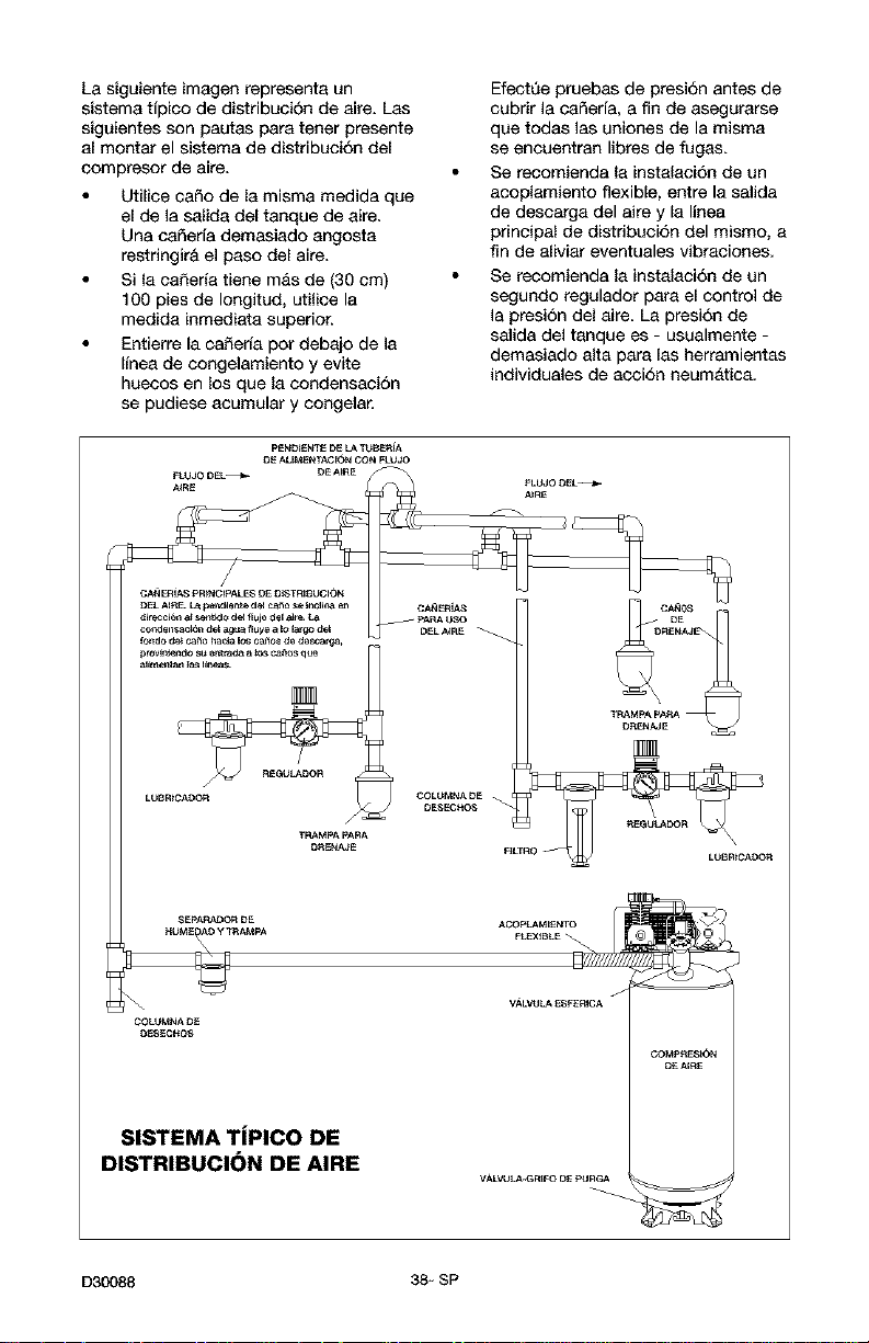
La siguiente imsgen represent8 un
sistema tipico de distribucion de aire. Lss
siguientes son pautas par8 tener presente
al montar el sistema de distribucion del
compresor de aire,
Utilice caflo de la misma medida que
el de la salida del tanque de aire.
Una caSeda demasiado angosta
restringir& el paso del aire.
Si la caSeri8 tiene m&s de (30 cm)
100 pies de Iongitud, utilice la
medida inmediata superior.
Entierre la ca_erf8 pot debajo de la
Ifnea de congelamiento y evite
huecos en los que la condensacion
se pudiese 8cumular y congelar.
EfectQe pruebas de presi6n antes de
cubrir la c85eria, a fin de asegursrse
que todas las uniones de la misma
se enouentran libres de fugss.
Se recomienda la instsIscion de un
acoplamiento flexible, entre la salida
de desearga del aire y la linea
principal de distribuci6n del mismo, a
fin de 81iviar eventuales vibrseiones.
Se recomienda la instsIscion de un
segundo regulador par8 el control de
la presion del 8ire. L8 presion de
salida del tsnque es - usualmente -
demasiado alta par8 18sherramientas
individuales de aeei6n neumAtic8.
pENDk£NTE DE LA TUB_iA
DE ALIMENTACI_,N CON FLU_3
_RE C FLUJO DEL_
AkRE
CAN_iA$ _R_NCkPALE8 DE {)kSTRISUOION
{)EL AIR£ La pemJ_e_te deJ ca_e _e Jmuflna e_
d_recc_6n a_se,_kl o d_ flu}e del a]te
cemlel_s_c_n dek agua f_uye a ko large dek
_do de_ca_e ha_ los ca_o_ de de_az£a,
prevl_o _ entraea a_ c=_os que
_]_mer_an _a_ I_neas.
DESECHC_
TRAMPA PARA
D_NA_ _LTR
_pARAOOR DE _
COWMNA DE
D_ECHOS
SISTEMA TJPICO DE
DISTRIBUCI(_N DE AIRE
VALV_LA.GR_FO DE PURGA
D30088 38 - SP

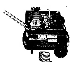
Conozca su compresor de aire
LEA ESTE MANUAL DEL PROPIETARIO Y SUS NORMAS DE SEGURIDAD ANTES DE
OPERAR LA UNIDAD. Compare las ilustraciones contra su unidad a fin de familiarizarse
con la ubicaci6n de los distintos controles y regulaciones. Conserve este manual para
referencias futuras.
Descripcibn de operaciones
Familiaricese con estos controles antes de
operar la unidad.
Interruptor
de presi6n
:lel tanque
V_lvula de segurltl_,,I
Interruptor On/Auto/Off: Mueva este
interruptor a la posici6n ON para dar
contacto automatieo el interruptor de
presi6n, y OFF para interrumpir la energia
electrica al t_rmino del uso.
Interruptor de preei6n: El interruptor de
presi6n permite el arranque autom&tico
del motor cuando la presi6n del tanque
disminuye por debajo del valor de la
presi6n de conexion regulada en fabrica.
El motor se detendra cuando la presion
del tanque alcance los valores de presi6n
de corte, regulado en fabrica para su
desconexi6n<
Valvula de seguridad: Si el interruptor de
presi6n dejara de cortar el suministro de
presi6n del compresor conforme a los
valores prefijados para la presi6n de corte,
la v&lvula de seguridad proteger& contra la
presi6n elevada, "saltando" de acuerdo a
los valores prefijados en f&brica
(ligeramente superiores a los de presion
de corte de la Ilave interruptora.)
Manbmetro de la presibn del tanque: El
man6metro que controla la presion del
tanque indica la reserva de presi6n del
tanque de aire,
V_lvula de asiento: Abre y cierra la
v&lvula de descarga de aire. Gire la perilla
en sentido antihorario pare abrir, yen
sentido horatio para cerrar.
V_lvela de drenaje: La v&lvula de drenaje
se eneuentra ubicada sobre la base del
tanque de aire y se usa para drenar la
condensaci6n al fin de cada uso.
Sistema de enfriamiento (no mostrado):
Este compresor contiene un sistema de
avanzada para el control de enfriamiento<
En el nL'_cleode este sistema de
enfriamiento hay un ventilador
espeeialmente disefiado< Resulta
perfectamente normal - para este
ventilador - soplar aire en grandes
cantidades a traves de los orificios de
ventilaci6n< De tal manera se podra saber
que el sistema de enfriamiento trabaja
cuando el aire esta siendo expelido.
Bomba de compresi6n del aire (no
mostrada): Comprime el aire dentro del
tanque. El aire de trabajo no se encuentra
disponible hasta que el compresor haya
alcanzado a Ilenar el tanque hasta un nivel
de presion pot encima del requerido para
la salida del aire.
39 + SP D30088
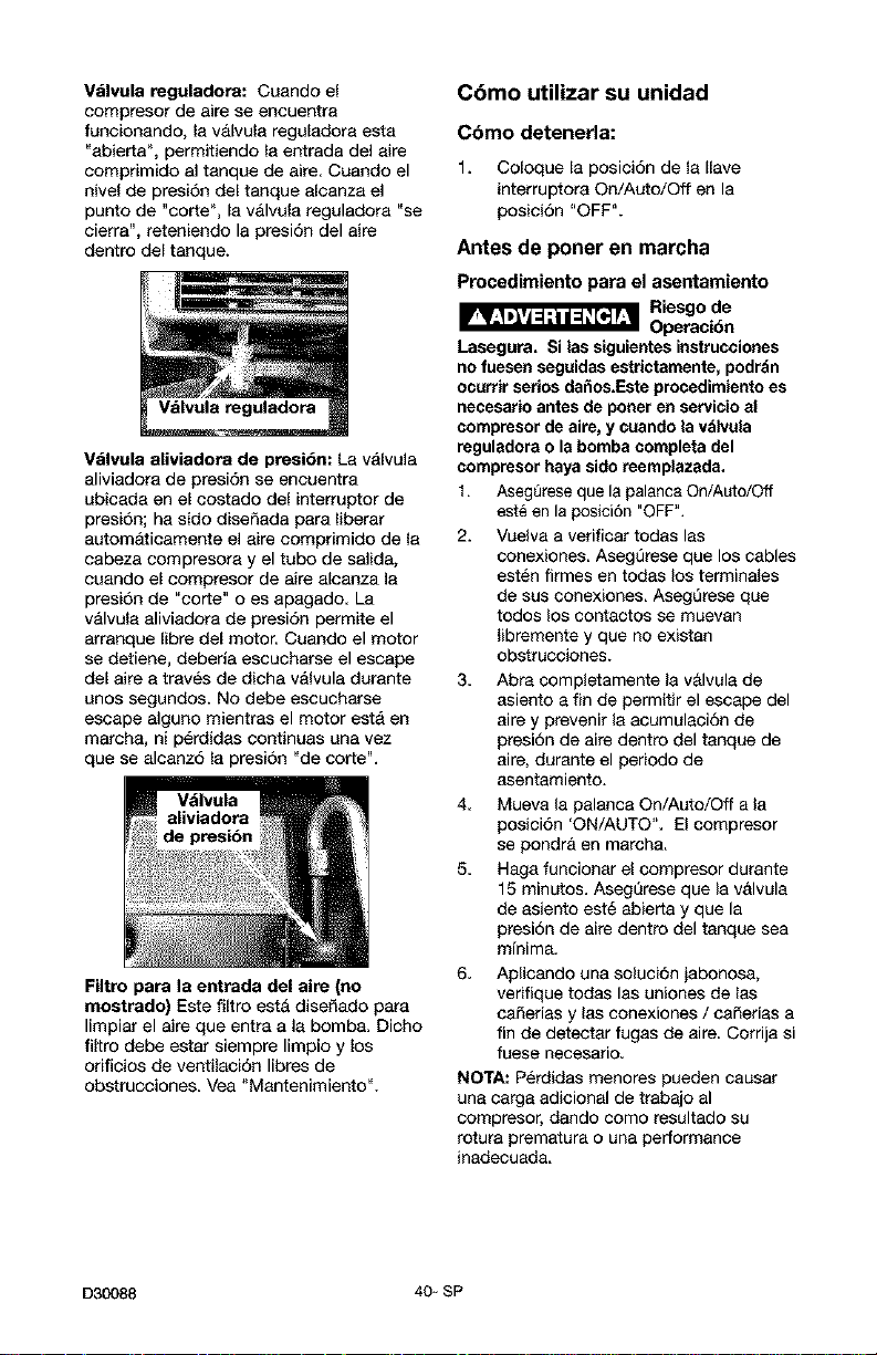
Valvula reguladora: Cuando el
compresor de aire se encuentra
funcionando, la valvula regalsdora est8
"abierta ", permitiendo la entrada del aire
comprimido al tanqae de aire< Cuando el
nivel de presi6n del tanque aleanz8 el
punto de "corte", 18v&lval8 regulador8 "se
cierra", reteniendo la presi6n del aire
dentro del tanque.
Valvula aliviadora de presibn: L8 v&lvula
aliviador8 de presi6n se encaentr8
ubicada en el costado del interruptor de
presi6n; ha sido diseSada para liberar
aatom&ticamente el aire comprimido de la
cabeza compresora y el tubo de salida,
caando el compresor de aire 81canza la
presion de "corte" 0 es apsgado< L8
valvula 81iviador8 de presi6n permite el
arranque libre del motor. Cuando el motor
se detiene, deberia escueharse el escape
del aire a traves de dicha valvula dursnte
unos segundos. No debe escucharse
escape alguno mientrss el motor esta en
march8, ni perdidas continuas una vez
que se 81canz6 18presi6n "de corte".
Filtro para la entrada del aire (no
mostrado) Este filtro esta dise_ado par8
limpiar el aire que entr8 ala bombs. Dicho
filtro debe estar siempre limpio y los
orificios de ventilsci6n libres de
obstrucciones< Vea "Mantenimiento".
Cbmo utilizar su unidad
Cbmo detenerla:
1. Coloque 18posici6n de la Ilave
interruptor8 On/Auto/Off en la
posici6n "OFF".
Antes de poner en marcha
Procedimiento para el asentamiento
_ Riesgo de
Operacidn
Lasegura. Si las siguientes instrucciones
no fuesen seguidas estrictamente, podrdn
ocutrir setios dahos.Este proeedimiento es
necesario antes de porter en servicio al
compresor de aire, y cuando la vdlvula
reguladora o la bomba complete del
compresor haya side reemplazada.
1. Assg_rese que lapalanca On/Auto/Off
est_ en la posici6n "OFF".
2. Vuelv8 a verificar todas las
conexiones. AsegQrese que los cables
esten firmes en todss los terminales
de sus conexiones. Asegt3rese que
todos los contactos se muevan
libremente y que no existan
obstrucciones.
3< Abra completamente la valvula de
asiento a fin de permitir el escape del
aire y prevenir 18acumulaci6n de
presi6n de aire dentro del tsnque de
aire, durante el periodo de
asentamiento.
4. Mueva la palanca On/Auto/Off ala
posici6n 'ON/AUTO". El compresor
se pondra en marcha.
5. Hag8 funcionar el compresor durante
15 minutos. AsegQrese que la valvula
de asiento est_ abierta y que la
presi6n de aire dentro del tsnque sea
minima.
6. Aplicando una soluci6n jabonosa,
verifique todas las uniones de 18s
085erias y 18s conexiones / caSerias a
fin de detectsr fugas de aire. Corrija si
fuese necesario.
NOTA: Perdidas menores pueden causer
una carga adicionel de trabajo al
compresor, dando como resultado su
rotura premature o una performance
inadecuada.
D30088 40- SP
7 Verifique la existencia de vibraci6n
excesiva< Reajuste o acuSe el pie del
compresor, si clio fuera necesario.
Luego de 15 minutos, cierre la
valvula de asiento. El aire recibido
elevara la presiSn hasta el punto de
"presiSn de corte ", y clio har&
detener al motor.
El compresor estara ahora listo para set
usado+
Antes de cada puesta en marcha
1,
2<
3<
Coloque el interruptor On/Auto/Off en la
posici6n "OFF" y cierre el regulador de
aire.
Cierrela v&lvula de asiento.
Conecte la manguera y accesorios
NOTA= Ouando se utilicen accesorios
especificados para menos de 175
PSI deber& instalarse ua regulador.
Riesgo de
Explosibn.
Demasiada presibn de aire podrb set la
causa de riesgo de explosibn. Verifique los
valores de mbxima presibn dados por el
fabricante de las herramientas neamaticas y
los accesorios, La presibn de salida del
regulador jambs debe excedet los valores
de mbxima presibn especificados.
Cbmo poner en marcha
1,
Mueva la palanca On/Auto/Off a la
posici6n "AUTO" y deje que se
incremente la presi6n del tanque. El
motor se detendra una vez alcanzado el
valor de presi6n"de corte" del tanque.
2. Cuando la presiSn del tanque
alcanza el valor de "presi6n de corte"
se abre la v&lvula de asiento.
tMPORTANTE: AI utilizar un regulador y
otros accesorios, refi_rase a las
instrucciones del fabricante<
41_ SP D30088
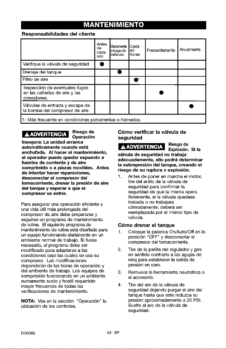
Responsabilidades del cliente
Verifique la v&lvula de seguddad
Drenaje del tanque
Filtro de aire
Inspecci6n de eventuales fugas
en las cafierfas de aire y las
conexiones.
Valvulas de entrada y escape de
la bomba del compresor de aire
Antes
de _amen_ Cada
duego de 40 Frecuentemente
oada :adauso horas
uso
1
Anualmente
1- Mas frecuente en condiciones polvorientas o ht_medas.
Riesgo de
Operaci6n
Insegura: La unidad arranca
automdticamente cuando esta
enchufada. AI hacer el mantenimiento,
el opetador puede quedar expuesto e
fuentes de Corriente y de aire
compfimido o a piezas moviblee. Antes
de intentar hacer reparaciones,
desconectar el compreeor del
tomecortiente, drenar la presi6n de aire
del tanque y esperar a que el
compresor se enfrie.
Pera esegurar una opereci6n eficiente y
una vida Qtil mas prolongada del
compresor de aire debe prepararse y
seguirse un programa de mantenimiento
de rutina. El siguiente programa de
mantenimiento de rutina est& dise_ado para
un equipo funcionando diariamente en un
ambiente normal de trebajo. Si fuese
necesario, el programa debe ser
modfficado para adaptarse alas
condiciones bajo les cuales se usa su
compresor, Las modificaciones
depender&n de las horas de operaci6n y
del ambiente de trabajo. Los equipos de
compresi6n funcionando en un ambiente
sumamente sucio y hostil requerir&n
mayor frecuencia de todas las
verificaciones de mantenimiento.
NOTA: Vea en la seccion "Operaci6n" la
ubicacion de los controles.
C6mo verificar la vdlvula de
seguridad
_ Riesgo de
Explosi6n. Si la
vdlvule de segurided no trabaja
adecuadamente, ello podra determinar
la sobrepresi6n del tanque, creando el
fiesgo de su ruptura o explosi6n.
1. Antes de poner en marcha el motor,
tire del anillo de la v&lvula de
seguridad para confirmar la
seguridad de que la misma opera
libremente, si la v&lvula quedase
trabada o no trabajara
c6modamente, deber& ser
reemplazada pot el mismo tipo de
v&lvula.
Cbmo drenar el tanque
1. Coloque la palanca On/Auto/Off en la
posici6n "OFF" y desconectar el
compresor del tomacorriente.
2.
Tire de la perilla del regulador y gire
en sentido contrario alas agujas de
reloj pare establecer la salida de
presi6n en cero.
3. Remueva la herramienta neumAtica o
el accesorio.
4. Tire del aro de la valvula de
segurided dejando purgar el aire del
tanque hesta que este reduzee su
presi6n aproximadamente a 20 PSL
Suelte el aro de la v&lvula de
seguridad.
D30088 42_SP
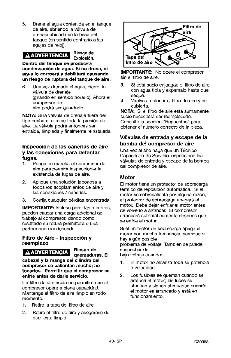
5+
Drene el agaa contenida en el tanque
de aire, abriendo la v&lvula de
drenaje ubicada en la base del
tanque (en sentido contrario a {as
agujas de reloj).
Riesgo de
Explosi6n.
Dentro del tanque se producirb
condensacibn de agua. Si no drena, el
agua Io corroerd y debilitard causando
un riesgo de ruptura del tanque de aire,
6+
Una vez drenada el agua, cierre la
valvula de drenaje
(girando en sentido horario). Ahora el
compresor de
aire podr& set guardado.
NOTA: Si la valvula de drenaje fuera del
tipo enchufe, elimine toda {a presi6n de
aire La v&lvula podra entonces ser
extraida, limpiada y finalmente reinstalad&
Inspecci6n de las ca_erJas de aire
y las conexiones para detectar
fugas.
1. Ponga en marcha el compresor de
airepara permitir inspeccionarla
existencia de ragas de aire+
2. Aplique una soluci6n jabonosa a
todos los acoplamientos de aire y
las eonexiones / caSerfas<
3. Corrija cualquier perdida encontrada
IMPORTANTE: Incluso p6rdidas menores,
pueden causar una carga adicional de
trabajo al compresor, dando como
resultado su rotura prematura o una
performance inadecuada<
Filtro de Aire - Inspeccibn y
reemplazo
_ Riesgo de
quemaduras, El
cabezal y la manga del cilindro del
compresor se ealientan mucho; no
tocarlos. Permitir que el compresor se
enfrie antes de darle servicio.
Un flltro de aire sucio no permitir& qua el
compresor opere a plena capecidad.
Mantenga el filtro de aire limpio en todo
momento<
1. Retire la tapa del filtro de aire.
2. Retire el filtro de aire y asegerese de
que est_ limpio.
IMPORTANTE: No opere el compresor
sin el filtro de aire.
3. Si est& sucio enjaague el filtro de aire
con agua tibia y exprfmalo hasta que
seque.
4. Vuelva a colocar el filtro de aire y su
cubierta<
NOTA: Si el filtro de aire est& sumamente
sucio neeesitara ser reemplazado<
Consulte la secci6n "Repuestos" para
obtener el nL'_meroeorrecto de la pieza<
Vdlvulas de entrada y escape de la
bomba del compresor de aire
Una vez al a_o haga queun T_cnico
Capecitado de Servicio inspeccione las
valvulas de entrada y escape de la bomba
del compresor de aire+
Motor
El motor tiene un protector de sobrecarga
t_rmico de reposiei6n automatica. Si el
motor se sobrecalienta por alguna raz6n,
el protector de sobrecarga apagar& el
motor. Debe dejar enfriar el motor antes
de volverlo a arrancar. El compresor
arrancara autom&ticamente despues que
se enfrfe el motor.
Si el protector de sobrecarga apaga el
motor con mucha frecuencia, verifique si
hay algt_n posible
problema de voltaje. Tambi_n se puede
sospechar de
bajo voltaje cuando:
1 El motor no alcanza toda su potencia
o velocidad<
2.
Los fusibles se queman cuando se
arranca el motor; las luces se
atent_an y siguen atenuadas cuando
el motor es arraecado y est& en
funcionamiento.
43- SP D30088
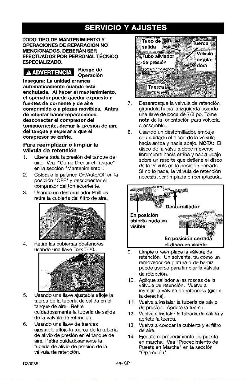
TODO TIPO DE MANTENIMIENTO Y
OPERACIONES DE REPARACION NO
MENCIONADOS, DEBEP_N SER
EFECTUADOS POR PERSONAL TI_CNICO
ESPECIALIZADO.
Riesgo de
Operaci6n
Insegura: La unidad arranca
automaticamente cuando esta
enchufada. AI hacer el mantenimiento,
el operador puede quedar expuesto a
fuentes de corriente y de aire
comprimido o a piezas movibles. Antes
de intentar hacer reperaciones,
desconectar el compresor del
tomacorriente, drenar la presidn de aire
del tanque y esperar a que el
compresor se enfrJe=
Para reemplazar o limpiar la
vblvula de retencibn
1. Libere toda la presi6n del tanque de
aire. Vea "C6mo Drenar el Tsnque"
en 18secci6n "Mantenimiento".
2. Coloque la palanca On/Auto/Off en la
posici6n "OFF" y desconectar el
compresor del tomacorriente.
3. Usando un destomillador Phillips
retire la cubiert8 del filtro de 8ire.
4 Retire las cubiertas posteriores
usando un8 Ilave Torx T-20
5 Usando un8 llave ajustable afloje 18
tuerc8 de la tuberi8 de salid8 en el
tanque de aire. Retire
cuidadosamente 18tuberfa de salida
de la valvul8 de retenci6n.
6 Usando un8 llave de tuercas
8justsble 8floje la tuerca de la tuberf8
de 81ivio de presi6n en el tanque de
8ire. Retire cuidsdosamente la
tuberfa de alivio de presi6n de la
vAlvula de retenci6n.
7=
8=
Desenrosque la v&lvul8 de retenci6n
gir&ndola haci8 la izquierda usando
una llsve de boca de 7/8 po. Tome
nota de la orientaci6n par8 volved8
8 ensamblar.
Usando un destomillador, empuje
con cuidado el disco de 18v&lvula
hacia ardba y hacia absjo. NOTA: El
disco de la v&lvula debe moverse
Iibremente haci8 arriba y hacia 8bajo
sobre un resorte que detiene el disco
de la v&lvul8 en la posici6n cerrad8.
Si no I0 hace, la v&lvula de retenci6n
necesita ser limpisda o reemplazsd&
el disco es visible
9 Limpie 0 reemplace 18v&lvula de
retenci6n. Un solvente, tal como un
removedor de pintur8 0 de bsmiz
puede usarse para {impiar {a valvu{8
de retenci6n.
10. Aplique sellador alas roscss de la
valvula de retenci6n. Vuelv8 a
instalar la valvula de retenci6n (gire a
18derechs).
11. Vuelv8 a instalar la tuberi8 de 81ivio
de presi6n. Apriete la tuerca.
12. Vuelv8 a instalar la tuberi8 de salid8 y
8priete 18tuerc8.
13. Vuelv8 a colocar 18cubierta y el filtro
de aire.
14. Ejecute el procedimiento de puest8
en march8. Ve8 "Proeedimiento de
Puesta en Marcha" en la secci6n
"Ope_ci6n".
D30088 44- SP
Antes de guarder su compresor de aire,
asegt3rese de hacer Io siguiente:
1. Revise la seeeion "Mantenimiento"
de las p&ginas precedentes y ejecute
el mentenimiento programado de
acuerdo a la necesidad<
2. Coloque la palanca On/Auto/Off en la
posiciSn "OFF" y desconectar el
compresor del tomacorriente.
3. Cierre la valvula de asiento
4. Extraiga la herramienta neum&tica o
el accesorio.
5.
Abra la valvula de asiento y
lentamente deje purgar el aire del
tanque de aire, hasta que la presi6n
del mismo Ilegue aproximadamente a
20 PSi.
6. Drene el agua del tanque de aire
abriendo la v&lvula de drenaje
ubicada en el fondo del tanque.
_ Riesgo de
Explosibn. El agua
se condensa dentro del tanque de aire.
Si no se drena, ella corroetd debilitando
las paredes del tanque de aire,
otiginando un riesgo de ruptura de sue
paredes.
7. Una vez que el agua haya sido
drenada, cierre la valvula de drenaje
NOTA: Si la v&lvula de drenaje estuviese
enchufada, libere toda la presion de aire
La valvula podr& set extrafda, limpiada y
luego reinstalad&
8. Proteja la manguera del aire de
da_os (tales como ser pisoteada o
caminar pot encima)<
45- SP D30088
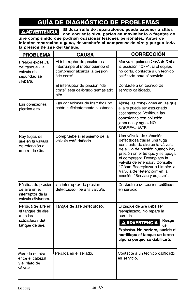
El desarrollo de reparaciones puede exponer a sitios
con corriente viva, partes en movimiento o fuentes de
aire comprimido que podrJan ocasionar lesiones personales. Antes de
intentar reparaci6n alguna, desenchufe el compresor de aire y purgue toda
la presi6n de aire del tanque.
CAUSA CORRECCION
PROBLEMA
Presi6n excesiva
del tanque - la
v&lvula de
seguridad se
dispara.
Las conexiones
pierden aire.
El interruptor de presi6n no
interrumpe al motor cuando el
compresor alcanza la presi6n
"de corte".
El interruptor de presidn "de
corte" esta calibrado demasiado
alto.
Las conexiones de los tubos no
est&n suficientemente ajustadas.
Compruebe si el asiento de la
v&lvula est& da_ado.
Hay fugas de
aire en la v&lvula
de retenci6n o
dentro de ella.
Mueva la palanca On/Auto/Off a
la posici6n "OFF", si el equipo
no corta, contacts a un tecnico
calificado para el servicio.
Contaete a un tecnico de
servicio calificado.
Ajuste las conexiones en las que
el aire puede set escuchado
escap_dose. Verifique las
conexiones con soluci6n
jabonosa y agua. NO
SOBREAJUSTE.
Una valvula de retenci6n
defectuosa causa una fuga
constante de aire en la valvula
de alivio de presi6n cuando hay
presi6n en el tanque y se apaga
el compresor. Reemplace la
v&lvula de retenci6n. Consulte
"Como Reemplazar o Limpiar la
Valvula de Retenci6n" en la
secci6n "Servico y adjuste%
P{_rdida de presi6n Un interruptor de presi6n Contacte a un tecnico calificado
de aire en el defectuoso libera la v&lvula, en servicio.
interruptor de la
v&lvula aliviadora.
P{_rdida de aire en Tanque de aire defectuoso.
Perdida en el sellado.
el tanque de aire
o en las
soldaduras del
tanque de aire.
Perdida de aire
entre el cabezal
y el plato de
vAlvula.
El tanque de aire debe ser
reemplazado. No repare la
perdida.
Riesgo
de
Explosibn. No perfore, suelde ni
modifique el tanque en forma
alguna porque se debilitard.
Contacte a un t_cnico calificado
en servicio.
D30088 46- SP

PROBLEMA CAUSA CORRECCION
Golpeteo. Posible defecto en la valvula Opere la valvula de seguridad
de seguridad, manualmente tirando de su anillo.
Si la valvula aun pierde, debera set
reemplazada.
Posible defecto en la v&lvula Extraiga y limpie o reemplace.
de seguridad.
Excesivo y prolongado uso del Disminuya la cantidad de uso de
mire. mire.
El compresor no
esta
suministrando
suficiente
cantidad de mire
para
operar los
accesorios.
El compresor no tiene
suficiente capacidad para el
requerimiento de mire al que
est& sometido.
Orificio en la manguera.
Valvula reguladora restringid&
P_rdida de air&
Filtro de entrada de mire
restringido.
Vedfique el requerimiento de mire
del accesorio. Si es mayor que
SCFM o la presi6n suministrada
pot su compresor de air& se
neoesita un oompresor de mayor
capacidad.
Verifique y reemplace si fuese
neoesario.
Extraiga, limpie o reemplace.
Ajuste las conexiones.
Limpie o reemplace el filtro de
entrada de air& No opere el
compresor de mire sin el filtro.
Consulte el parrafo "Filtro de Aire"
en la secci6n "Mantenimiento%
47_ SP D30088
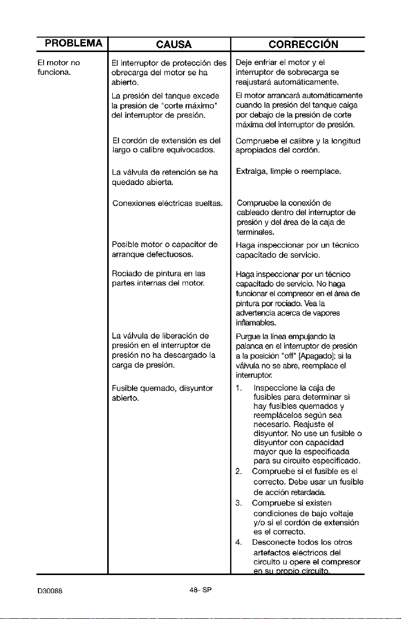
PROBLEMA
El motor no
funciona.
CAUSA CORRECCI(_N
El interruptor de protecci6n des
obrecarga del motor se ha
abierto<
La presi6n del tanque excede
la presion de "corte maximo"
del interruptor de presi6n.
El cord6n de extensi6n es del
largo o calibre equivocados.
La v&lvula de retenci6n se ha
quedado abiert&
Conexiones electricas sueltas.
Posible motor o capacitor de
arranqae defectuosos.
Rociado de pintura en las
)artes intemas del motor.
_av&lvula de liberaci6n de
)resi6n en el interruptor de
)resi6n no ha descargado la
;arga de presi6n.
Fusible quemado, disyuntor
abierto.
Deje enfriar el motor y el
interruptor de sobrecarga se
reajustar& autom&ticamente
El motor arrancar& automaticamente
cuando la presi6n del tanque caiga
For debajo de la presi6n de corte
m&xima del interruptorde presi6n<
Compruebe el calibre y la Iongitud
apropiados del cord6n
Extraiga, Iimpie o reemplace.
Compruebe laconexi6n de
cableado dentro del interraptor de
presion y del area de la caja de
terminales.
Haga inspeccionar pot un tecnico
capacitado de servicio.
Haga inspeccionar FOr un tecnico
capacffado de servicio. No haga
funcionar elcomprescr en el &tea de
pintura For rociado. Vea la
advertencia acerca de vapores
inflamables<
Purgue la Ifneaempujando la
palanca en el interruptor de presion
a la Fosici6n "off" [Apagado]; el la
v_lvula no se abre, reemplace el
interruptor<
1. Inspeccioae la caja de
fusibles para determinar si
hay fusibles quemados y
reempl&celos segQn sea
necesario. Reajaste el
disyantor. No use un fusible o
disyantor con capacidad
mayor qua la especificada
para su circaito especificado.
2. Compruebe si el fusible es el
correcto. Debe usar un fusible
de accion retardada.
3. Compruebe si existen
condiciones de bajo voltaje
y/o si el cordon de extensi6n
es el correcto.
4. Desconecte todos los otros
artefactos electricos del
cirsuito u opere el compresor
en stJDrODiOclrcuito.
D30088 48- SP

49*SP D30088

D30088 50-SP
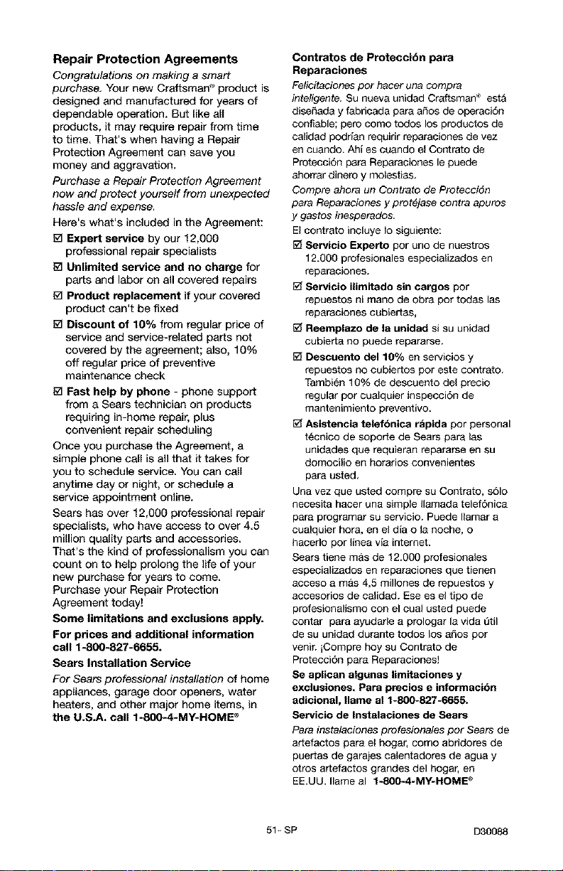
Repair Protection Agreements
Congratulations on making a smart
purchase. Your new Craftsman '_product is
designed and manufactured for years of
dependable operation. But like all
products, it may require repair from time
to time. That's when having a Repair
Protection Agreement can save you
money and aggravation.
Purchase a Repair Protection Agreement
now and protect yourself from unexpected
hassle and expense.
Here's what's included inthe Agreement:
[_ Expert service by our 12,000
professional repair specialists
[_ Unlimited service and no charge for
parts and labor on all covered repairs
[_ Product replacement if your covered
product can't be fixed
1_ Discount of 10% from regular price of
service and service-related parts not
covered by the agreement; also, 10%
off regular price of preventive
maintenance check
[_ Fast help by phone - phone support
from a Sears technician on products
requiring in-home repair, plus
convenient repair scheduling
Once you purchase the Agreement, a
simple phone call is all that it takes for
you to schedule service. You can call
anytime day or night, or schedule a
service appointment online.
Sears has over 12,000 professional repair
specialists, who have access to over 4.5
million quality parts and acceesodee.
That's the kind of professionalism you can
count on to help prolong the life of your
new purchase for years to come.
Purchase your Repair Protection
Agreement today!
Some limitations and exclusions apply.
For prices and additional information
call 1-800-827-6655.
Sears Installation Service
For Sears professional installation of home
appliances, garage door openers, water
heaters, and other major home items, in
the U.S.A. call f-800-4*MY-HOME _
Contratos de Preteccibn para
Reparaciones
Felicitaciones per hater una compra
inteligente, Su nueva unidad Craftsman ® est&
diseffada y fabricada para afros de operaci6n
confiable; pero come todos los productos de
ca_idad podrian requirir reparaciones de vez
en cuando. Ahi es cuando e_ Contrato de
Protecc}6n para Reparac}ones le puede
ahorrar dinero y motestias.
Cornpre ahora un Contrato de Protecci6n
para Reparaciones y prot_jase contra apuros
y gastos inesperados,
Et contrato incluye _o siguiente:
Servicio Experto per uno de nuestros
12.000 profesionales especializados en
reparaciones.
Servicio ilimitado sin cargos per
repuestos ni mane de obra per todas las
reparaciones cubiertas,
Reemplazo de la unidad si su unidad
cubierta no puede repararse.
Descuento del 10% en servicios y
repuestos no eubiertos per este contrato.
Tambi6n 10% de descuento del precio
regular per cualquier inspecci6n de
mantenimiento preventive.
Asistencia telefbnica rbpida per personal
t6cnico de soporte de Sears para tas
unidades que requieran repararse en su
domocilio en horarios convenientes
para usted.
Una vez que usted compre su Contrato, s61o
necesita hacer una simple Ilamada telef6nica
para programar su servicio. Puede Ilamar a
cua_quier hera, en et dia o la noche, o
hacerlo per linea via intemet.
Sears tiene mas de 12.000 profesionales
especializados en reparaciones que tienen
acceso amas 4,5 millones de repuestos y
accesorios de calidad. Ese es et tipo de
profesionalismo con el cual usted puede
contar para ayudarte a prologar la vida etil
de su unidad durante todos los afros per
venir, iCompre hey su Contrato de
Protecci6n para Reparaciones]
Se aplican algunas limitaciones y
exclusiones. Para precios e irrformacibn
adicional, Ilame al 1-800-827-6655.
Servicio de Instalaciones de Sears
,Data instalaciones profesionales per Sears de
artefactos para el hogar, come abridores de
puertas de garajes calentadores de agua y
otros artefactos grandes del hogar, en
EE.UU. Ilame al t-S00-4-MY-HOME _
51 _ SP D30088
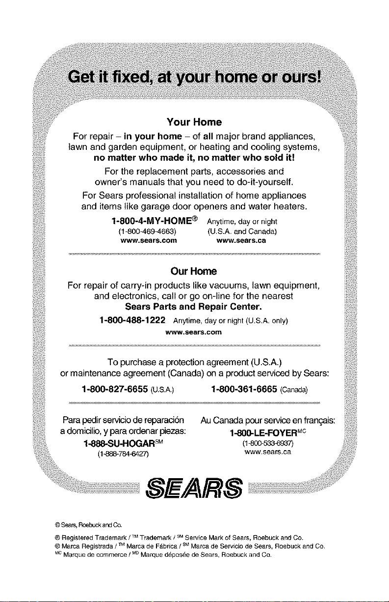
Your Home
For repair - in your home - of all major brand appliances,
lawn and garden equipment, or heating and cooling systems,
no matter who made it, no matter who sold it!
For the replacement parts, accessories and
owner's manuals that you need to do-it-yourself.
For Sears professional installationof home appliances
and itemslike garage door openers and water heaters.
1-800-4-MY-HOME ® Anytime, day or night
(I-800-469-4663) (U,S,A. and Canada)
w_/w.sesrs=com www.sears.c_
OurHome
For repair of carry-in products like vacuums lawn equipment,
and electronics, call or go on-line for the nearest
Sears Parts and Repair Center.
1-800-488-1222 Anytime,dayornight(U.S,A,only)
www.sears.com
To purchase a protectionagreement (U.S.A.)
or maintenance agreement (Canada) on a product servicedby Sears:
1-800-827-6655 (U.S.A.) 1-800-361-6665 (Canada)
Para pedir servicb de reparad6n
a domicUb, y para ordenar piezas:
1-888-SU-HOGAR sM
(1-888-784--8427)
Au Canadapourserviceen francois:
1-800.LE-FOYERMc
(1-80e-_7)
SE/AR$
© Sears,Roebuck andCo.
® Registered Trademark / TMTrademark / sMService Mark of Sears Roebuck and Co.
® Marca Registr_da / TMM_rca de F_bdca / s_ Marca de Se_vicio de Sears, Roebuck and Co.
vc Marque de commerce / MDM_rque d_pos_e de Sears, Roebuck and Co.