Loading ...
Loading ...
Loading ...
Page 16
mrcool.com
Unit Installation
CAUTION
Ensure that all power supply is disconnected prior to installing the heat kit.
A means of strain relief and conductor protection must be provided at the supply wire entrance into cabinet.
Only use copper conductors.
Installation must follow National Electric Code (NEC) and other applicable codes.
If this appliance is installed in an enclosed area such as a garage or utility room with any carbon monoxide
producing appliance, ensure the area is properly ventilated to the outside.
A filter dryer is recommended for installation based on nominal tonnage.
Use 0.96 as approximate SCFM correction factor for wet coil.
•
•
•
•
•
•
•
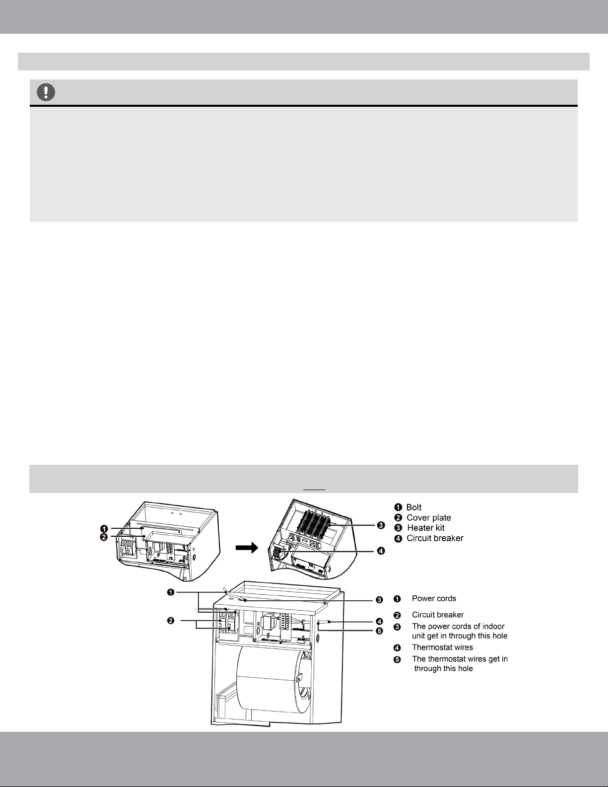
1. Remove the upper access panel from the air handler.
2. Remove the cover plate inside the upper access panel of the air handler.
3. Slide the heat kit into the slot and secure element plate with previously removed screws.
4. Make sure to insert the supporting poles of the heat kit into the supporting hole of the air handler.
5. Connect the quick connection plug and fasten the loose wires by using wire ties.
6. Install the circuit breaker into the mounting rail, break out the appropriate area of the plastic circuit
breaker cover on the access panel of the air handler.
7. a. When installing the MHK05U, MHK08U, or MHK10U (2-3 Ton) use the following steps. Connect the
power from the Circuit Breaker Panel to L1 and L2 of the circuit breaker included with the electric heat
kit.
b. When installing the MHK15U and MHK20U (4-5 Ton) use the following steps. Connect two separate
lines of power from the Circuit Breaker Panel to L1 and L2 of the two circuit breakers included with the
electric heat kit.
c. When connecting the electric heat kit to the air handler, use the Molex Plug Wiring Harness from the
electric heat kit and attach it to the Molex Plug Wiring Harness coming from air handler’s PCB board.
d. Replace access panel and check operation.
Fig 2.13
NOTE: The Molex Plug Connection will power the air handler. So, a separate source of incoming
power for L1 & L2 terminals on the air handler is NOT needed when using an electric heat kit.
Electric Heat Kit Installation (continued)
Loading ...
Loading ...
Loading ...