
8E/ S
CRoFTZHHNO
MODEL NUMBER 917.258590 OWNER'SMANUAL
° Assembly
• Operation
° Customer Responsibilities
oService and Adjustments
o Repair Parts
CAUTION: Read and follow all safety rules and instructions before operating this equipment.
FOR CONSUMER ASSISTANCE HOT LINE, CALL THIS TOLL FREE NUMBER: 1-800-659_5917
SAFETY RULES
Safe Operation Practices for Ride-On Mowers
IMPORTANT: THIS CUTTING MACHINE 1S CAPABLE OF AMPUTATING HANDS AND FEET AND THROWING OBJECTS,.
FAILURE TO OBSERVE THE FOLLOWING SAFETY INSTRUCTIONS COULD RESULT IN SERIOUS INJURY OR DEATH+
I, GENERAL OPERATION
• Read,understand,and followallinstructionsinthe manual
andonthe machinebeforestarting+
• Only allow responsibleadults,who are familiar with the
instructions,to operatethe machine.
• Clear the area of objectssuch as rocks,toys,wire, etco,
whichcouldbe pickedupand thrownbythe blade°
• Besuretheareaisclearofo.therpeoplebeforemowing°Stop
machineif anyoneentersthe area.
• Nevercarrypassengers+
° Donotmowinreverseunlessabsolutelynecessary.Always
lookdownand behindbeforeandwhilebacking.
o Beaware ofthe mowerdischargedirectionanddo notpoint
it at anyone..Do not operatethe mowerwithouteitherthe
entiregrasscatcheror theguard inplace.
• Slowdownbeforeturning+
• Neverleavea rurmingmachineunattended°Alwaysturnoff
blades,set parkingbrake,stop engine, and removekeys
before dismounting°
• Turnoffbladeswhennot mowing+
• Stop enginebefore removinggrasscatcheror unclogging
chute.
• MowonlyIn daylightorgoodartificial light.
• Do not operate the machinewhileunderthe influenceof
alcoholordrugs°
• Watchfor trafficwhenoperatingnearorcrossingroadways°
= Useextra carewhenloadingor unloadingthe machineinto
atrailerortruck°
il. SLOPE OPERATION
Slopes are a major factor related to loss-of-control and
tipover accidents, which can result in severe injury or
death. All slopes require extra caution. If you cannot back
up the slope or if you feel uneasy on it, do not mow it.
DO:
• Mow up and down slopes, not across.
= Remove obstacles such as rocks, tree limbs, etc.
• Watch for holes, ruts, or bumps. Uneven terrain could
overturn the machine. Tall grass can hide obstacles.
• Use slow speed° Choose a low gear so that you will not have
to stop or shift while on the slope.
• Follow the manufacturer's recommendations for wheel
weights or counterweights to improve stability.
o Use extra care with grass catchers or other attachments.
These can change the stability of the machine.
• Keep all movement on the stopes slow and gradual Do not
make sudden changes in speed or direction.
• Avoid starting or stopping on a slope+. If tires lose traction,
disengage the blades and proceed slowly straight down the
slope+
DO NOT:
° Do not turnon slopes unlessnecessary, and then, turnslowly
and gradually downhill, if possible+
° Do not mow near drop+offs, ditches, or embankments. The
mower could suddenly turn over if a wheel is over the edge
of a cliffor ditch, or if an edge caves in°
• Do not mow on wet grass. Reduced traction could cause
sliding.
° Do not try to stabilize the machine by putting your foot on the
ground_
° Do not use grass catcher on steep slopes.
!11. CHILDREN
Tragic accidents can occur if the operator is not alert to the
presence of children. Children are often attracted to the
machine and the mowing activity, Never assume that
children will remain where you last saw them.
• Keep childrenout of the mowing area and under the watchful
care of another responsible adult.
° Be alert and turn machine off if children enter the area°
• Before and when backing, look behind and down for small
children.
• Never carry children. They may fall off and be seriousIy
injured or interfere with safe machine operation+
• Never allow chiidren to operate the machine.
• Use extra care when approaching blind comers, shrubs,
trees, or other objects that may obscure vision.
IV. SERVICE
,, Use extra care in handlinggasoline and otherfuels. "Theyare
flammable and vapors are explosive..
Use only an approved container,
Never remove gas cap or add fuel with the engine
running+ Allow engine to cool before refueling+ Do not
smoke.
Never refuel the machine indoors.
Never store the machine or fuel container inside where
there is an open flame, such as a water heater_
• Never run a machine inside a dosed area.
• Keep nuts and bolts, especially blade attachment bolts, tight
and keep equipment in good condition+
• Never tamper with safety devices° Check their proper
operation regularly°
• Keep machine free of grass, leaves, or other debris build-up.
Clean oil or fuel spillage. Allow machine to cool before
storing°
° Stop and inspect the equipment if you strike an object+
Repair, if necessary, before restarting..
• Never make adjustments or repairs with the engine running.
• Grass catchercomponents are subjectto wear, damage, and
deterioration, which could expose moving parts or allow
objects to be thrown. Frequently check components and
replace withmanufacturer's recommended parts, when nec-
essary+
° Mower blades are sharp and can cut.. Wrap the blade(s) or
wear gloves, and use extra caution when servicing them_
° Check brake operation frequently. Adjust and service as
required.
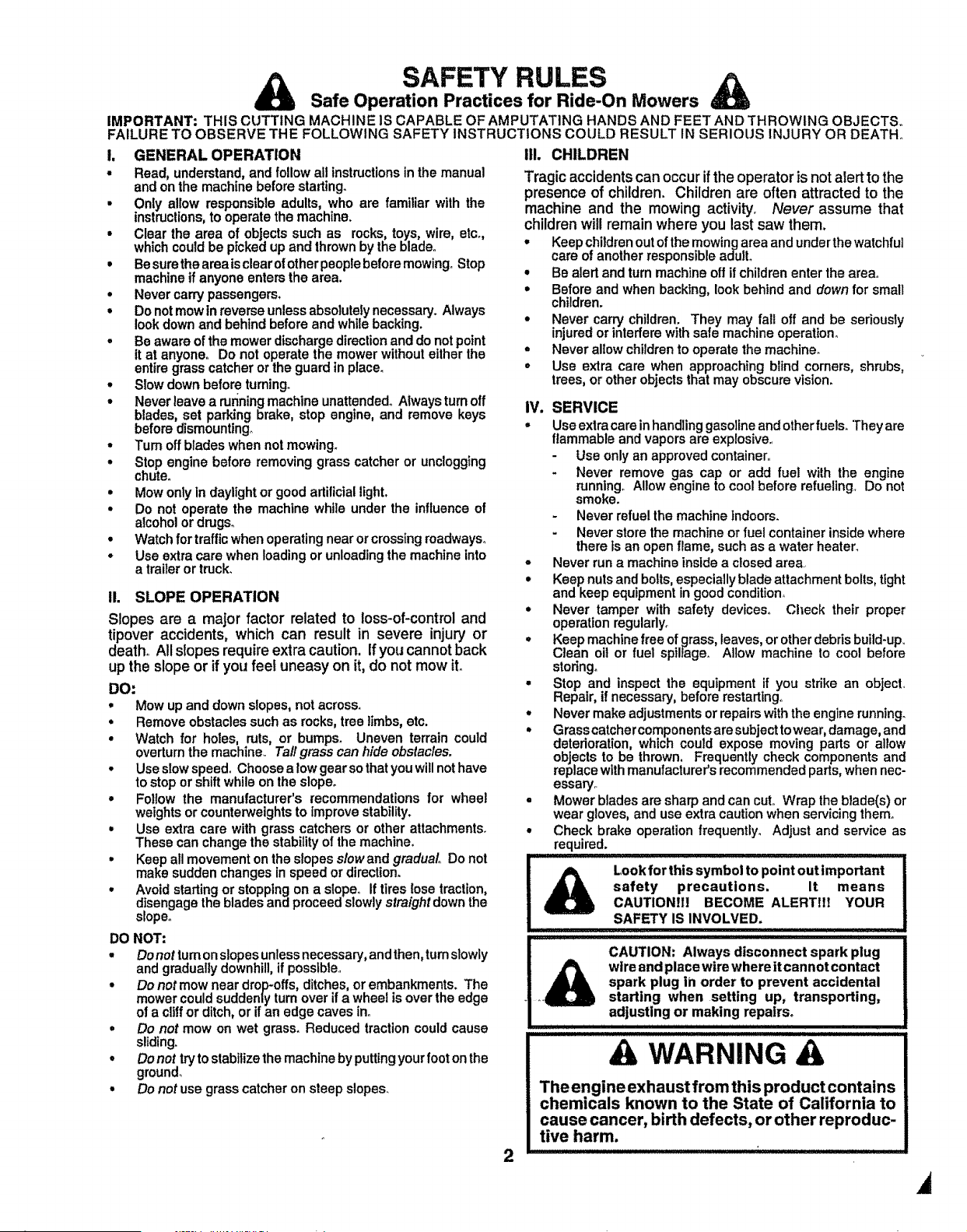
Look for this symbol to point out important
safety precautions. It means
CAUTIONfl! BECOME ALERTltf YOUR
SAFETY IS INVOLVED.
CAUTION: Always disconnect spark plug
wtre and placewtre where it cannot contact
spark plug in order to prevent accidental
_+ starting when setting up, transporting,
adjusting or making repairs+
!: L] !!' !! ! !] !!'!!]!]!!]!]!!!J!!J!! !!]!!!!!]!'! !!
A WARNING
The engine exhaust from this product contains
chemicals known to the State of California to
cause cancer, birth defects, or other reproduc-
tive harm.
,i
CONGRATULATIONS on your purchase of a Sears
tractor. It has been designed, engineered and manufac-
tured to give you the best possible dependability and
performance_
Should you experience any problem you cannot easily
remedy, please contact your nearest Sears Service Cen-
tedDepartment. We have competent, well-trained tech-
nicians and the proper tools to service or repair this trac-
toro
Please read and retain this manual. The instructions witt
enable you to assemble and mahtain your tractor prop-
edy, Always observe the "SAFETY RULES".
MODEL
NUMBER 917.258590
SERIAL
NUMBER
DATE OF PURCHASE
THE MODELAND SERIAL NUMBERS WILL BE FOUND
ON A PLATE UNDER THE SEAT.
YOU SHOULD RECORD BOTH SERIAL NUMBER AND
DATE OF PURCHASE AND KEEP IN A SAFE PLACE
FOR FUTURE REFERENCE.
MAINTENANCE AGREEMENT
A Sears maintenance agreement is available on this prod-
uct. Contact your nearest Sears store for details.
CUSTOMER RESPONSIBILITIES
• Read and observe the safety rules.
° Follow a regular schedule in maintaining, caring for and
using your tractor.
• Follow the instructions under "Customer Responsibili-
ties" and "Storage" sections of this owner's manual
PRODUCT SPECIFICATIONS
HORSEPOWER: 16
GASOLINE CAPACITY 35 GALLONS
AND TYPE: UNLEADED REGULAR
OIL TYPE (API-SF/SG): SAE 10W-30 (above 32'_F)
SAE 5W-30 (below 32°F)
OIL CAPACITY: W/FILTER: 4.0 PINTS
W!O FILTER: 35 PINTS
SPARK PLUG: CHAMPION RC12YC
(GAP: .040")
VALVE CLEARANCE: NOT ADJUSTABLE
GROUND SPEED (MPH): FORWARD: 5_5
REVERSE: 2_4
TIRE PRESSURE: FRONT: 14 PSI
REAR: 10 PSi
CHARGING SYSTEM: !5 AMPS @ 3600 RPM
BATTERY: AMP/HR: 30
MtN CCA: 240
CASE SIZE: UIR
BLADE BOLT TORQUE: 30_35 FT, LBS.
WARNING: This tractor is equipped with an internal
combustion engine and should not be used on or near any
unimproved forest-covered, brush-covered or grass-coy -
ered land unless the engine's exhaust system is equipped
with a spark arrester meeting applicable local or state laws
(if any)_ If a spark arrester is used, it should be maintained
in effective working order by the operator
In the state of California the above is required by law
(Section 4442 of the California Public Resources Code).
Other states may have similar laws. Federal laws apply on
federal lands. A spark arrester for the muffler is available
through your nearest Sears Authorized Service Center
(See REPAIR PARTS section of this manual).
i Hi lIHllllllIHIHlllllll'llIH,lllllllllllmlll.,,
LIMITED TWO YEAR WARRANTY ON CRAFTSMAN RIDING EQUIPMENT
For two (2) years from the date of purchase, if thisCraftsman Riding Equipment is maintained, lubricated and tuned up according
to the instructions in the owner's manual, Sears witl repair or replace, free of charge, any parts found to be defective in material
or workmanship.
This Warranty does not cover:
• Expendable items which become worn during no_mal use, such as blades, spark plugs, air cleaners, belts, etc
° Tire replacement or repair caused by punctures from outside objects, such as nails, thorns, stumps, or glass
• Repairs necessary because of operator abuse, negligence, improperstorage or accident or the failure to maintain the
equipment according to the instructions contained in the owner's manual,
• Riding equipment used for commercial or rental purposes
LIMITED 90 DAY WARRANTY ON BATTERY
For ninety (90) days from date of purchase, if any battery included with this riding equipment proves defective in material or
workmanship and our testing determines the battery will not hold a charge, Sears will replace the battery at no charge
IN-HOME WARRANTY SERVICE ON YOUR CRAFTSMAN RIDING EQUIPMENT IS AVAILABLE AT NO-CHARGE FOR 30
DAYS FROM THE DATE OF PURCHASE PLEASE CONTACT YOUR NEAREST SERVICE CENTER. AFTER 30 DAYS
FROM THE DATE OF PURCHASE, WARRANTY SERVICE IS AVAILABLE BY TAKING YOUR CRAFTSMAN RIDING EQUIP*
MENT TO YOUR NEAREST SEARS SERVICE CENTER. (1N-HOME WARRANTY SERVICE WILL STILL BE AVAILABLE
AFTER 30 DAYS FROM THE DATE OF PURCHASE BUT A STANDARD TRIP CHARGE WILL APPLY.) THIS WARRANTY
APPLIES ONLY WHILE THIS PRODUCT IS IN THE UNITED STATES,
This Warranty gives you specific legal rights,and you may also have other rightswhich may vary from state to state
SEARS, ROEBUCK AND CO, D/817 WA, HOFFMAN ESTATES, IL 60179
3
FABLE OF
lllllllllll llllll,,llll, lllll, lllll i ill J ii i i .................................................................................
SAFETY RULES ......... '.......... '....................................... 2
PRODUCT SPECIFICATIONS ...................................... 3
CUSTOMER RESPONSIBILITIES ..................... 3, 16-19
WARRANTY .................................................................. 3
TRACTOR ACCESSORIES .......................................... 5
ASSEMBLY .............................................................. 7-10
OPERATION ........................................................... 11-16
MAINTENANCE SCHEDULE ...................................... 17
SERVICE AND ADJUSTMENTS ............................ 21-27
STORAGE ................................................................... 28
TROUBLESHOOTING ............................................ 29-30
REPAIR PARTS - TRACTOR ................................. 32-49
REPAIR PARTS- ENGINE .................................... 50-55
PARTS ORDERINGISERVICE ................ BACK COVER
INDEX
A
Accessories ........................................................5
Adjustments:
Brake ..............................................................24
Carburetor .................................................27
Mower
Front-To-Back ......................... 22
Side-To*Side ...................................22
Throttle Control Cable .........................27
Air Filter, Engine..................................................20
Air Screen, Engine ................................................19
Assembly ......................................................7-10
B
Battery:
Charging ................................................8
Cleaning .............................................18
Starting with Weak Battery .......... 26
Storage ..........................................................28
Terminals ..............................................18
Belt:
Motion Drive
RemovallReplacement ............ 24
Mower Belt(s)
Removal/Replacement .........o.......23
Blade:
Sharpening ....................................................18
Replacement .............................................18
Brake Adjustment .............................................24
C
Carburetor Adjustment ........................................27
Controls, Tractor .................................................!2
Customer Responsibilities ...................17-20
Engine:
Air Filler .........................................................20
Air Screen ....................................19
Cooling Fins ..........................................20
Engine Oil ..........................................15,19
Fuel Filter ........................................20
Spark Plug(s) ..............................20
Tractor:
Battery ..........................................................18
Blade ...............................................18
Lubrication Chart .............................17
Maintenance Schedule ............ 17
Tire Care .......................................8,18,25
Transaxle ........................................19
Cutting Height, Mower ...............................13
E
Electrical:
Interlocks and Relays .........................26
Schematic ....................................................31
Widng Diagram .............................. 32
Engine:
Air Filter .....................................................20
Air Screen ................................................................19
Cooling Fins ...............................................20
Oil Change ........................................................19
Oil Level ......................................... 19
Oil Type ...................................................15,19
Preparation .................................... 15
Repair Parts ............................ 50-55
Starting ...............................................................15
Storage .....................................................28
F
Filter:
Air Filter ......................................... 20
Fuel .......................................................................20
Fuel:
Type ......................................................................15
Storage .........................................................28
Fuse ............................................................................26
H
Hood Removal/Installation ......................26
M
Maintenance Schedule ...............................17
Mower:
Adjustment, Front-to*Back ................22
Adjustment, Side-to-Side .............. 22
Blade Replacement .................................18
Blade Sharpening ................................18
Cutting Height .............................................13
Installation ...................................... 29
Operation .................................................14
Removal ........................................................2!
Mowing Tips .....................................................16
Muffler ..........................................................20
Spark Arrester ....................................3,40
OiI:
O
Cold Weather Conditions .............15,19
Engine ....................................................19
Storage .....................................................28
Operation .......................................................12-16
Operating Mower ..................................................!4
Options:
Accessories ........................................5
Spark Arrestor ..........................................3,40
P
Parking Brake ................................ 12-13
Parts Bag ..............................................................6
Parts, Replacement/Repair ...................32-49
Product Specifications ..............................3
R
Repair Parts ................................................32-55
S
Safety Rules .........................................................2
Seat ...............................................................8
Service and Adjustment_, ......................21-27
Carburetor ..................................................27
Fuse .....................................................26
Hood Remova!/Instaltation ...............26
Motion Drive Belt
Removal/Replacement ............ 24
Mower Belt(s)
Remova!/Replacement ................23
Mower Adjustment
Front-to-Back ...................................22
Side-to-Side ...................................22
Mower Removal/Installation ......... 21
Tire Care ...................................................8,18,25
Slope Guide Sheet ...........................................59
Spark Plug(s) ..............................................................20
Specifications ....................................................3
Starting the Engine .................................15
Steering Wheel .......................................7,25
Stopping the Tractor .....................................t3
Storage ..............................................................28
T
Throttle Control Cable Adjustment ........27
Tires ..........................................................8,18,25
Trouble Shooting Chart .......................29-30
Transaxle ........................................................t9
W
Warranty ....................................................................3
Wiring Diagram ..............................................32
Wiring Schematic ...........................................31
4
A Ri AND ATTACHMENTS
These accessories and attachments were available throughmost Sears retail outlets and service centers when the tractorwas purchased..
Most Sears stores can order these items for you when you provide the model number of your tractor.
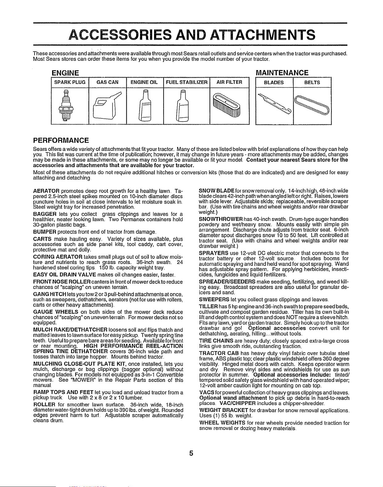
ENGINE
SPARK PLUG
GAS CAN
ENGINEOIL FUEL STABILIZER
AIR FILTER
%
MAINTENANCE
BLADES BELTS
PERFORMANCE
Sears offers a wide variety of attachments that fit your tractor° Many of these are listedbelow with brief explanations of how they can help
you. This list was current at the time of publication; however, it may change in future years - more attachments may be added, changes
may be made in these attachments, or some may no longer be available or fit your model. Contact your nearest Sears store for the
accessories and attachments that are available for' your tractor.
Most of these attachments do not require additional hitches or conversion kits (those that do are indicated) and are designed for easy
attaching and detaching.
AERATOR promotes deep root growth for a healthy lawn. Ta-
pered 2.5-inch steel spikes mounted on 10-inch diameter discs
puncture holes in soil at close intervals to let moisture soak in.
Steel weight tray for increased penetration.
BAGGER lets you collect grass clippings and leaves for a
healthier', nearer looking lawn_ Two Permanex containers hold
30-gallon plastic bags.
BUMPER protects front end of tracLor from damage.
CARTS make hauling easy.. Variety of sizes available, plus
accessories such as side panel kits, tool caddy, cart cover,
protective mat and dolly.,
CORING AERATOR takes smal! plugs out of soil to allow mois-
ture and nutrients to reach grass rools. 36-inch swathe 24
hardened steel coring tips 150 Ibl.capacity weight tray_
EASY oIL DRAIN VALVE makes oil changes easier, faster_
FRONT NOSE ROLLER canters in front of mower deck to reduce
chances of "scalping" on uneven terrain_
GANG HITCH lets you tow 2 or 3 pull-behind attachments at once,
such as sweepers, dethatchers, aerators (not for use with rollers,
carts or other heavy attachments).
GAUGE WHEELS on both sides of the mower deck reduce
chances of"scalping" on uneven terrain. For mower decks not so
equipped_
MULCH RAKE/DETHATCHER loosens soil and flips thatch and
matted teaves to lawn surface for easy pickup. Twenty springtine
teeth..Usefulto prepare bare areas for seeding. Available for front
or rear mounting. HIGH PERFORMANCE REEL-ACTION
SPRING TINE DETHATCHER covers 36-inch wide path and
tosses thatch into large hopper_ Mounts behind tractor'.
MULCHING CLOSE-OUT PLATE KII", once installed, lets you
mulch, discharge or bag clippings (bagger optional) without
changing blades._For models not equipped as 3-in-1 Convertible
mowers.. See "MOWER" in the Repair Parts section of this
manual.
RAMP TOPS AND FEET let you load and unload tractor from a
pickup truck. Use with 2 x 8 or 2 x 10 lumber,
ROLLER for smoother _awn surface. 36-tnch wide, 18-inch
diameter water-tight drum holds up to 390 Lbs.of weight. Rounded
edges prevent harm to tuff. Adjustable scraper automatically
cleans drum..
SNOW BLADE forsnow removaL only, !4-inch high,48-inch wide
blade clears 42-inch pathwhen angled left or right. Raises, lowers
with side lever. Adjustable skids; replaceabIe, reversible scraper
bar.. (Use with tire chains and wheel weights and/or rear drawbar
weight..)
SNOWTHROWER has 40-inch swath.. Drum-type auger handles
powdery and wet/heavy snow. Mounts easily with simple pin
arrangement. Discharge chute adjusts from tractor seat.. 6-inch
diameter spout discharges snow 10 to 50 feet, Lift controlled at
tractor seat, (Use with chains and wheel weights and/or rear
drawbar weight.)
SPRAYERS use 12-volt DC electric motor that connects to the
tractor battery or other 12-volt source, includes booms for
automatic spraying and hand held wand for spot spraying, Wand
has adjustable spray pattern. For applying herbicides, insecti-
cides, fungicides and liquid fertilizers..
SPREADER/SEEDERS make seeding, fertilizing, and weed kill-
ing easy.. Broadcast spreaders are also useful for granular de-
icers and sand°
SWEEPERS let you collect grass clippings and leaves.
TILLER has 5 hp engine and 36-inch swath to prepare seed beds,
cultivate and compost garden residue... Titier has its own built-in
liftand depth control system and does NOT require a sleeve hitch..
Fits any lawn, yard or garden tractor. Simply hook up to the tractor
drawbar and go_ Optional accessories convert unit for
dethatching, aerating, hitl[ng._..without too_s.
TIRE CHAINS are heavy duty; closely spaced extra-large cross
links give smooth ride, outstanding traction.
TRACTOR CAB has heavy duty vinyl fabric over tubular steel
frame, ABS plastic top;clear plasticwindshield offers 360 degree
visibility.. Hinged metal doors with catch, Keeps operator warm
and dry. Remove vinyl sides and windshields for use as sun
protector' in summer° Optional accessories include: tinted/
tempered solid safety glass windshield with hand operated wiper;
12-volt amber caution light for mounting on cab top.
VACS for powerful collection of heavygrass clippings and reaves.
Optional wand attachment to pick up debris in hard-to-reach
places. VAC/CHIPPER includes a chipper-shredder..
WEIGHT BRACKET for drawbar for snow removal applications.
Uses (t) 55 tb..weight..
WHEEL WEIGHTS for rear wheels provide needed traction for
snow removal or dozing heavy materials.
5
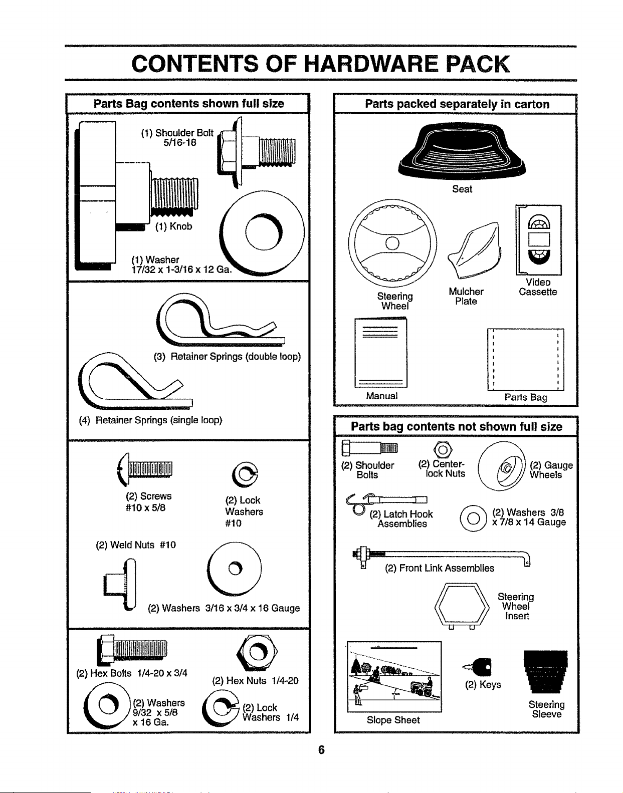
CONTENTS OF HARDWARE PACK
(1) Shoulder Bolt
5/16-18
(1) Knob
(1) Washer
17/32 x 1-3/16 x 12 Ga
lL__tainer Springs (double loop)
(4) Retainer Springs (single loop)
(2) Screws (2) Lock
#10 x 5/8 Washers
#10
(2) Weld Nuts #10
I_ (2) Washers 3/16 x 3/4 x 16 Gauge
(2) Hex Bolts 1/4-20 x 3/4
(2) Washers
9/32 x 5/8
x 16Ga.
(2) Hex Nuts 1/4_20
(2) Lock
Washers 1/4
Parts packed separately in carton
Seat
Steering Mulcher
Wheel Plate
Manual
_ : ii1,11 IIIIIIII
Video
Cassette
!
Parts Bag
,11111,,,1111111,111ii1,1,1,i, iii
Parts bag contents not shown full size
iii
(2) Shoulder (2) Center- (2) Gauge
Bolts lockNuts Wheels
_k _ (2) Washers 3/8
• x 7/8 x 14 Gauge
_(2) Front Link Assemblies
Steering
Wheel
Insert
t
Slope Sheet
(2) Keys
Steering
Sleeve
6
BLY
Your' new tractor has been assernbled at the factory with excL_ptionof those parts left unassembled for shipping purposes_
To ensure safe and proper' operation of your tractor, all parts and hardware you assemble must be tightened securely. Use
the correct tools as necessary to insure proper' tightness_
TOOLS REQUIRED FOR ASSEMBLY
A socket wrench set will make assembly easier. Standard
wrench sizes are listed_
(1) 3/4" wrench (2) 7/16" wrench
(1) 9/16" wrench Utility knife
(1) 1/2" wrench Tire pressure gauge
(!) 3/4" socket w/drive ratchet
When right and left hand is mentioned in this manual, it
means when you are in the operating position (seated
behind the steering wheel).
TO REMOVE TRACTOR FROM CARTON
UNPACK CARTON
- Remove all accessible loose parts and parts cartons
from carton (See page 6)_
• Cut, from top to bottom, along lines on all four corners
of carton, and lay panels flat.
• Remove mower and packing materials_
o Check for any additional loose parts or cartons and
remove_
BEFORE ROLLING TRACTOR OFF
SKID
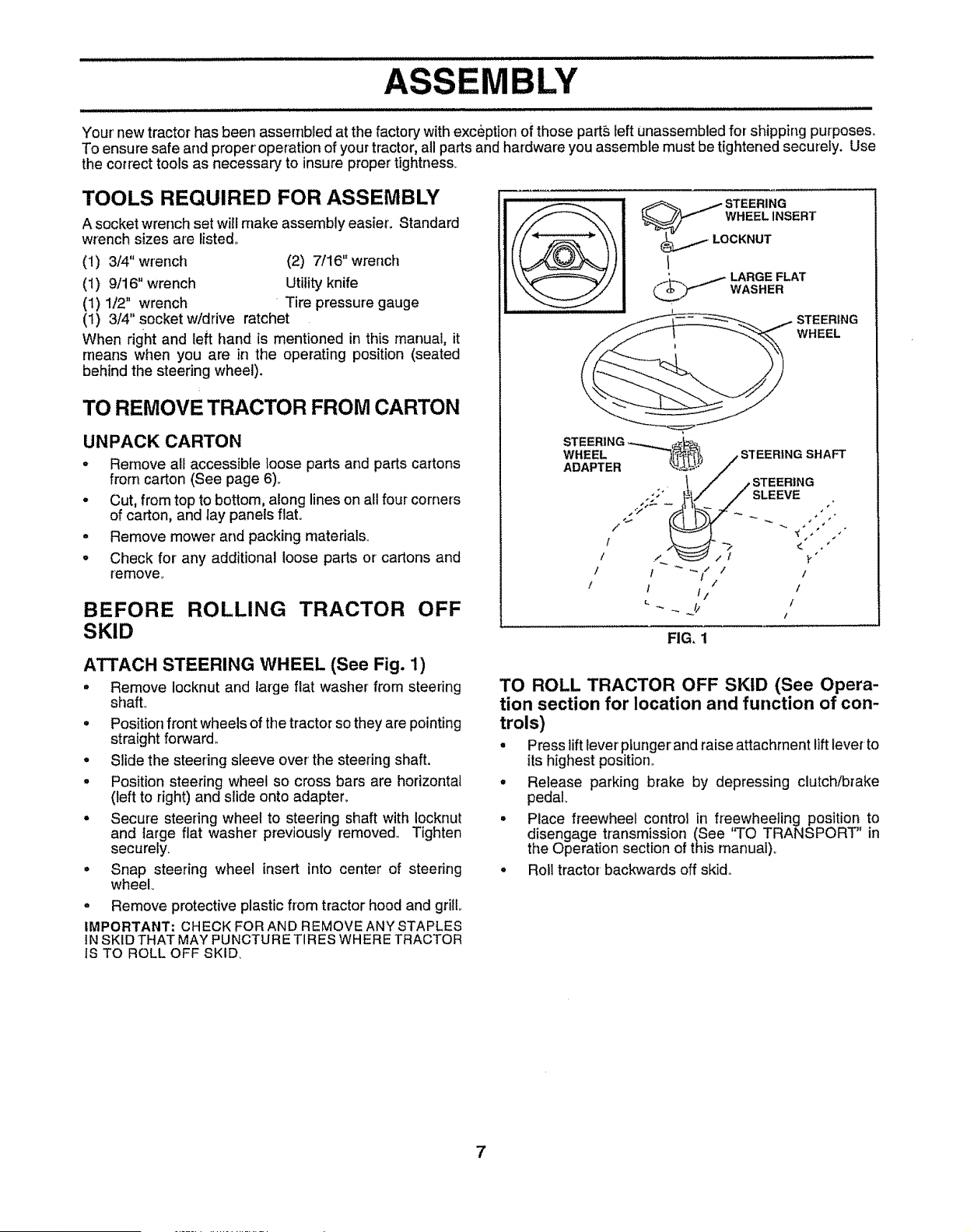
ATTACH STEERING WHEEL (See Fig. 1)
• Remove Iocknut and large flat washer from steering
shall
• Positionfront wheels of the tractor so they are pointing
straight forward,,
• Slide the steering sleeve over' the steering shaft.
o Position steering wheel so cross bars are horizontal
(left to right) and slide onto adapter.
• Secure steering wheel to steering shaft with Iocknut
and large flat washer previously removed,, Tighten
securely,
° Snap steering wheel insert into center of steering
wheel°
° Remove protective plastic from tractor hood and grill
IMPORTANT: CHECK FOR AND REMOVE ANY STAPLES
IN SKID THAT MAY PUNCTURE TIRES WHERE TRACTOR
IS TO ROLL OFF SKID,
Fi="-. _ LARGE FLAT
_ WASHER
t f 1/ /
/ 1 t/ /
_ _ _ .._// I /
FIG. 1
TO ROLL TRACTOR OFF SKID (See Opera-
tion section for location and function of con-
trols)
• Press lift lever plungerand raise attachment lift leve_to
its highest position.
• Release parking brake by depressing clutch/brake
pedal°
• Place freewheel control in freewheeling position to
disengage transmission (See 'q'O TRANSPORT" in
the Operation section of this manual),.
• Roll tractor backwards off skid,,
7
BLY
illll iill illlllll i Ill Ill I Illlll I IIIIl,I III IIII Illll Illllll
CONNECT BATTERY(See Fig. 2)
IIIIIII IIIIIIIII I IIIIIIIIIIII III IIIIIIIIIIIIII I II IIIII IIIII IIIIII II IL
CAUTION: Do not short battery termi-
nals. Before connecting battery, re-
move metal bracelets, wristwatch
bands, rings, etc.
Positive terminal must be connected
first to prevent sparking from acciden-
tal grounding.
• Lifthood to raised position,i
. Open terminal access doors, remove terminal protec-
tive caps and discard_
• If this battery is put into service after month and year
indicated on label (label located between terminals)
charge battery for minimum of one hour at 6-10 amps,.
• First connect RED battery cable to positive (+) battery
terminal with hex bolt, flat washer, lockwasher and hex
nut as shown. Tighten securely.
• Connect BLACK grounding cable to negative (-)battery
terminal with remaining hex bolt, flat washer, lock
washer and hex nuL Tighten securely°
• Close terminal access doors.
Use terminal access doorsfor:
° Inspection for secure connections (to tighten hard-
ware).
• Inspection for corrosion.
• Testing battery,
- Jumping (if required).
• Periodic charging,
LOCK FLAT
HEX NUT WASHER WASHER
DISCARD TERMINAL _ _ HEX
PROTECTIVE CAPS \ _ '_ BOLT
.....f._-.o oo. . .......
TERMI'hAI_"'! i_ = •
ACCESS
DOOR ', "!;>_'_"_]_ _,_lll!l_--_ POSITIVE
; 1 °ABLE
J_
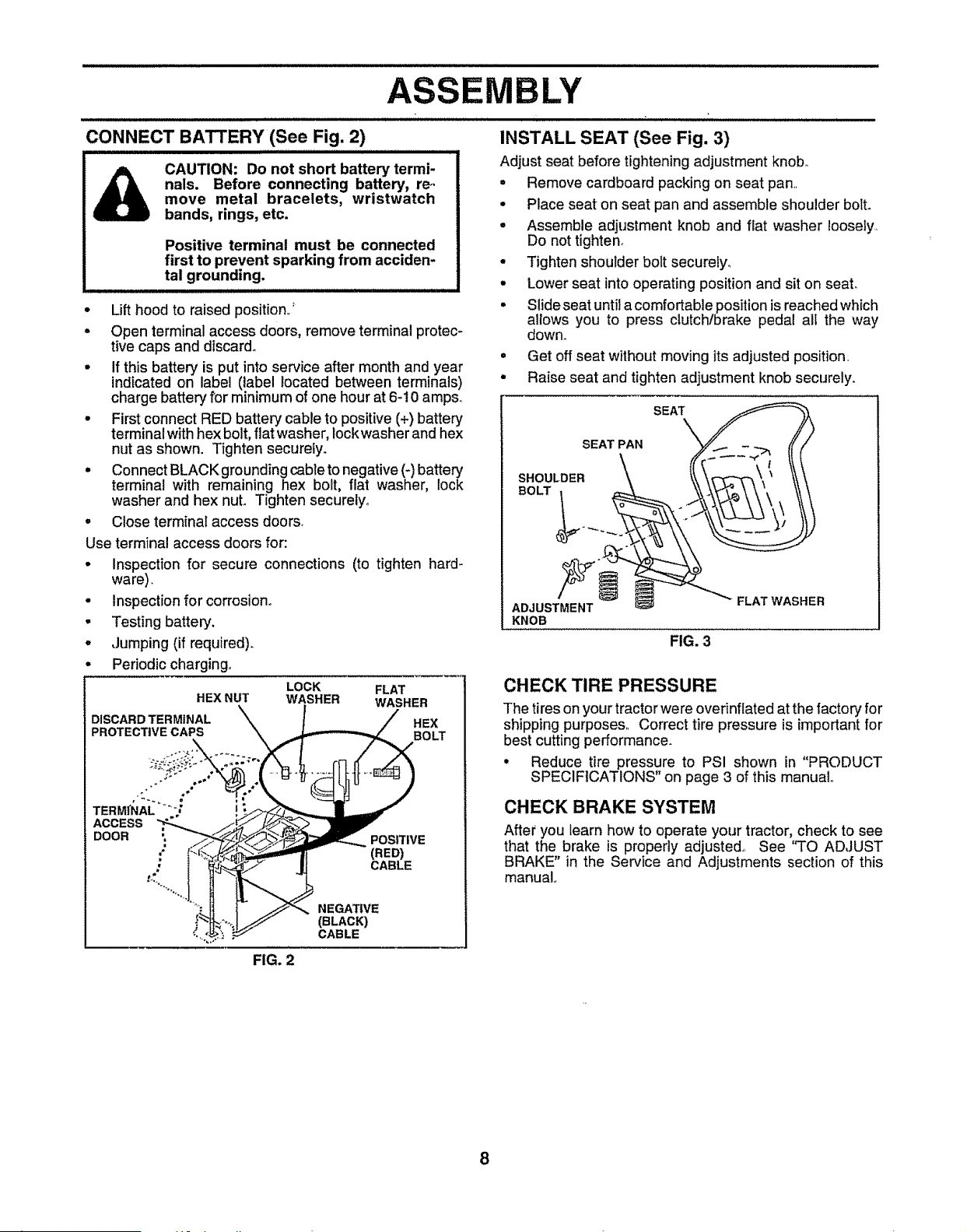
INSTALL SEAT (See Fig. 3)
Adjust seat before tightening adjustment knob°
• Remove cardboard packing on seat pan.
• Place seat on seat pan and assemble shoulder bolt.
- Assemble adjustment knob and flat washer loosely.,
Do not tighten.
• Tighten shoulder bolt securely..
° Lower seat into operating position and sit on seal
• Slide seat until a comfortable position is reached which
allows you to press clutchlbrake pedal all the way
down.
• Get off seat without moving its adjusted position_
• Raise seat and tighten adjustment knob securely.
SHOULDER _ _ \_ _,' \\ \
BOLT . _-_ o \\"\_="'-_'_-\ \ " \\\
AD,UST EN,
KNOB
FIG. 3
CHECK TIRE PRESSURE
The tireson your tractorwere overinflatedat the factory for
shipping purposes° Correct tire pressure is important for
best cutting performance.
• Reduce tire pressure to PSI shown in "PRODUCT
SPECIFICATIONS" on page 3 of this manual
CHECK BRAKE SYSTEM
After you learn how to operate your tractor, check to see
that the brake is properly adjusted,, See "TO ADJUST
BRAKE" in the Service and Adjustments section of this
manual..
FIG. 2
8
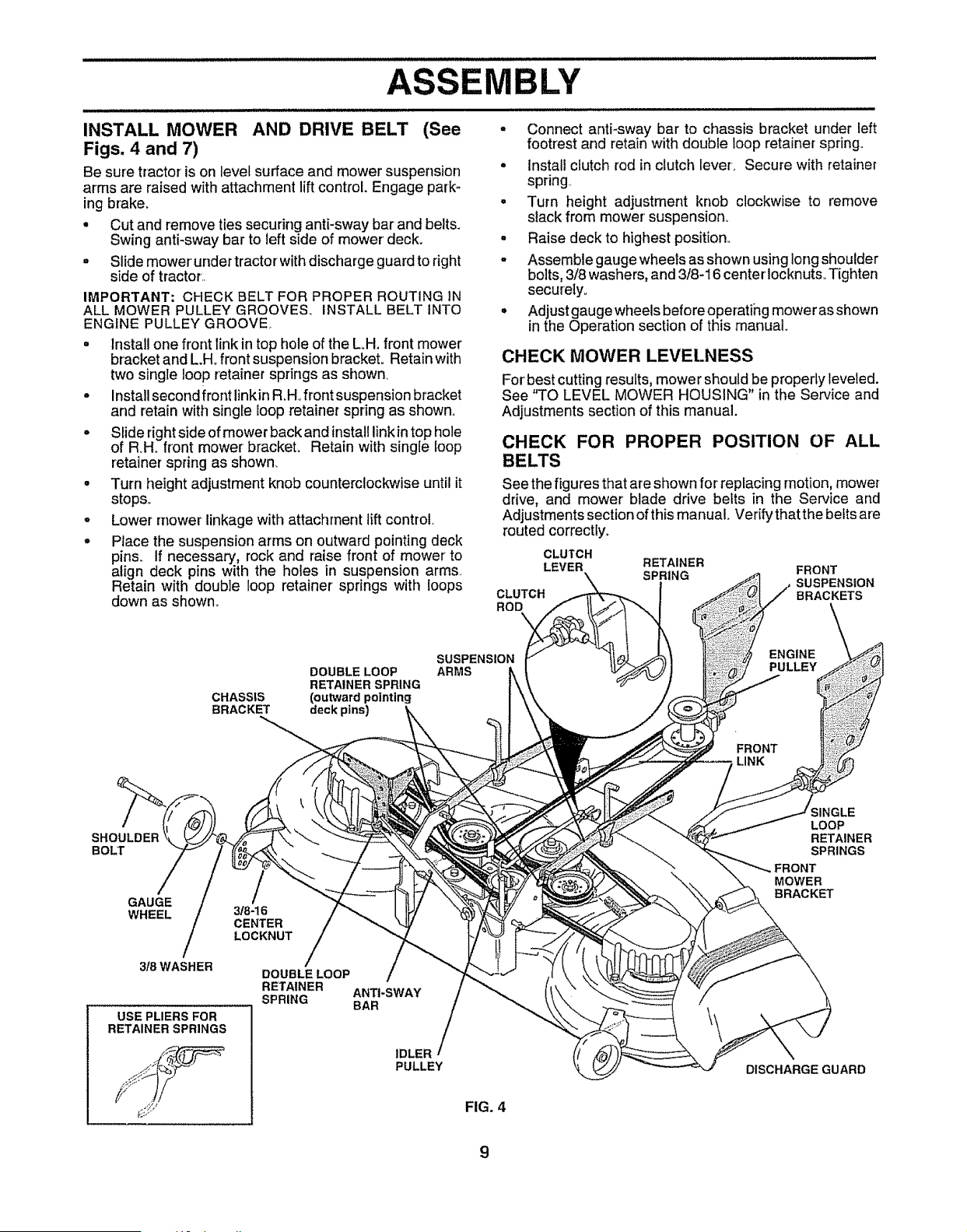
INSTALL MOWER AND DRIVE BELT (See
Figs. 4 and 7)
Be sure tractor is on level surface and mower suspension
arms are raised with attachment lift control. Engage park-
ing brake.
• Cut and remove ties securing anti-sway bar and belts.
Swing anti-sway bar to left side of mower deck.
- Slide mower' under tractorwith discharge guardto right
side of tractor..
IMPORTANT: CHECK BELT FOR PROPER ROUTING IN
ALL MOWER PULLEY GROOVES. INSTALL BELT INTO
ENGINE PULLEY GROOVE.
• Install one front link in top hole of the Loll. front mower
bracket and L.H. front suspension brackeL Retain with
two single loop retainer springs as shown.
• Install second front linkin R.Hofront suspension bracket
and retain with singEeloop retainer spring as shown.,
- Slide rightside of mower back and install link in top hole
of RH_ front mower bracket. Retain with single loop
retainerspring as shown.
• Turn height adjustment knob counterclockwise until it
stops°
o Lower mower linkage with attachment lift control.
• Place the suspension arms on outward pointing deck
pins, If necessary, rock and raise front of mower to
align deck pins with the holes in suspension arms,
Retain with double loop retainer springs with loops
down as shown.
BLY
. Connect anti-sway bar to chassis bracket under left
footrest and retain with double loop retainer spring°
• Install clutch rod in clutch lever-. Secure with retainer
spdng
. Turn height adjustment knob clockwise to remove
slack from mower' suspension.
o Raise deck to highest position..
- Assemble gaugewheels as shown using Iongshoulder
bolts, 3/8 washers, and 3/8-16 centerlocknuts_ Tighten
securely_
° Adjust gauge wheels before operatihg mower as shown
inthe Operation section of this manual.
CHECK MOWER LEVELNESS
For best cutting results, mower should be properly leveled.
See "TO LEVEL MOWER HOUSING" in the Service and
Adjustments section of this manual.
CHECK FOR PROPER POSITION OF ALL
BELTS
See the figures that are shown for replacing motion, mower
drive, and mower blade drive belts in the Service and
Adjustments section of this manual Verify that the befts are
routed correctly.
CLUTCH
LEVER
CLUTCH
ROD
RETAINER
SPRING FRONT
SUSPENSION
BRACKETS
DOUBLE LOOP
RETAINER SPRING
CHASSIS (outward pointing
BRACKET deck pins)
SUSPENSION
ARMS
ENGINE
PULLEY
FRONT
LINK
SHOULDER
BOLT
GAUGE
WHEEL
3/8WASHER
USE PLIERS FOR
RETAINER SPRINGS
318-16
CENTER
LOCKNUT
DOUBLE LOOP
RETAINER
SPRING
ANTI-SWAY
BAR
IDLER
PULLEY
FIG. 4
SINGLE
LOOP
RETAINER
SPRINGS
MOWER
BRACKET
DISCHARGE GUARD
9
ASSEMBLY
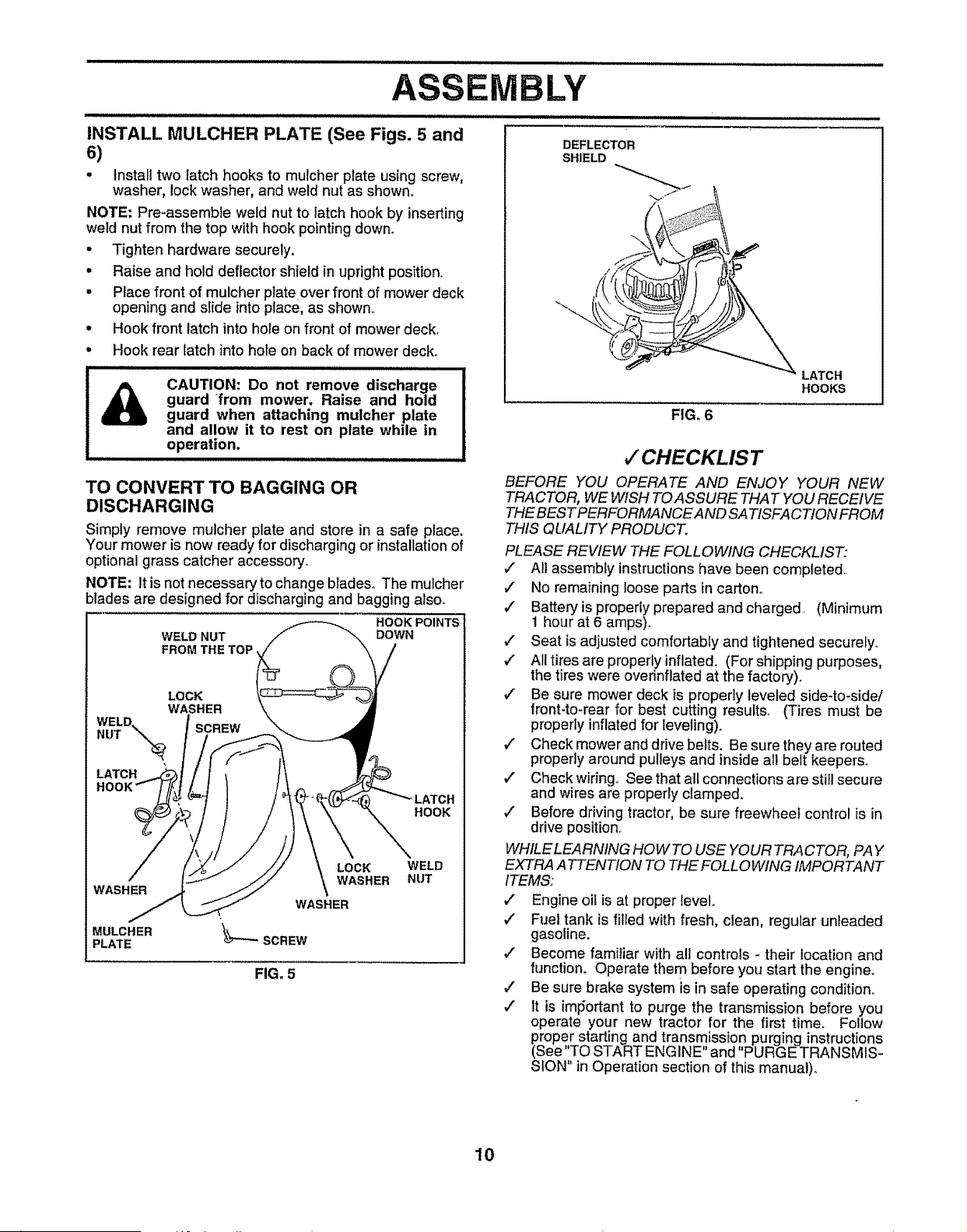
INSTALL MULCHER PLATE (See Figs. 5 and
6)
• Install two latch hooks to mulcher plate using screw,
washer, lock washer, and weld nut as shown.
NOTE; Pre-assemble weld nut to latch hook by inserting
weld nut from the top with hook pointing down.
• Tighten hardware securely.
° Raise and hold deflector shield in upright position..
• Place front of mulcher plate over front of mower deck
opening and slide into place, as shown..
° Hook front latch into hole on front of mower deck.
• Hook rear latch into hole on back of mower deck.
i, .................................................!
CAUTION: Do not remove discharge
guard from mower. Raise and hold
guard when attaching mulcher plate
and allow it to rest on plate while in
operation.
TO CONVERT TO BAGGING OR
DISCHARGING
Simply remove mulcher plate and store in a safe place.
Your mower is now ready for discharging or installation of
optional grass catcher accessory.
NOTE; It is not necessary to change blades° The mulcher
blades are designed for discharging and bagging also.
WELD NUT
FROM THE TOP
HOOK POINTS
DOWN
LOCK
WASHER
WELD. SCREW
NUT "_
LATCH
HOOK
WASHER
MULCHER
PLATE
LOCK
WASHER
WASHER
_'_-SCREW
WELD
NUT
FIG. 5
DEFLECTOR
SHIELD
FIG. 6
LATCH
HOOKS
v"CHECKLIST
BEFORE YOU OPERATE AND ENJOY YOUR NEW
TRACTOR, WE WISH TO ASSURE THAT YOU RECEIVE
THE BESTPERFORMANCEAND SATISFACTION FROM
THIS QUALITY PRODUCT.
PLEASE REVIEW THE FOLLOWING CHECKLIST:
¢" All assembly instructions have been completed..
,/ No remaining loose parts in carton.
v" Battery is properly prepared andcharged (Minimum
1 hour at 6 amps).
v" Seat is adjusted comfortably and tightened securely.
,," All tires are properly inflated. (For shipping purposes,
the tires were ovednflated at the factory).
,./ Be sure mower deck is properly leveled side-to-side/
front-to-rear for best cutting results. (Tires must be
properly inflated for leveling).
v" Check mower and drive belts. Be sure they are routed
properly around pulleys and inside all belt keepers.
#" Check wiring. See that all connections are still secure
and wires are properly clamped.
v" Before driving tractor, be sure freewheel control is in
drive position.
WHILE LEARNING HOW TO USE YOUR TRACTOR, PAY
EXTRA A TTENTION TO THE FOLLOWING IMPORTANT
ITEMS:
,/ Engine oil is at proper Ievel.
,/ Fuel tank is filled with fresh, clean, regular unleaded
gasoline.
,/ Become familiar with all controls - their location and
function. Operate them before you start the engine.
_" Be sure brake system is in safe operating condition,
,z It is imtdortant to purge the transmission before you
operate your new tractor for the first time. Follow
roper starting and transmission purging instructions
See "TO START ENGINE" and "PURGE TRANSMIS-
SION" in Operation section of this manual).
10

OPERATION
HJlIH,
These symbols may appear on your tractor or' in literature supplied with the prodi]ct Learn and understand their meaning,.
+
BATTERY CAUTION OR REVERSE
WARNING
ENGINE ON ENGINE OFF OIL PRESSURE
FORWAR D FAST SLOW
CLUTCH LIGHTS ON LIGHTS OFF
FUEL CHOKE MOWER HEIGHT DIFFERENTIAL PARKING BRAKE UNLOCKED
LOCK LOCKED
MOWER LIFT
REVERSE NEUTRAL
ATTACHMENT
CLUTCH ENGAGED
HIGH
LOW PARKING BRAKE
ATTACHMENT
CLUTCH DISENGAGED
IGNITION
DANGER, KEEP HANDS AND FEET AWAY
HYDROSTATIC FREE WHEEL
(Hydro Models only)
11
i lUl ill i i,i1_,,,_,,,_.... _,,
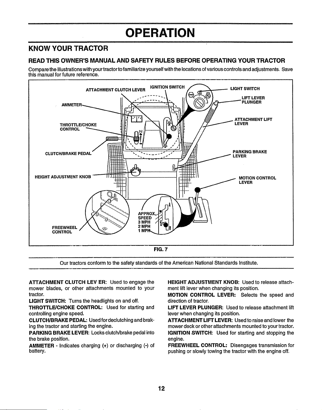
KNOW YOUR TRACTOR
OPERATION
READ THIS OWNER'S MANUAL AND SAFETY RULES BEFORE OPERATING YOUR TRACTOR
Comparethe illustrationswithyourtractor tofamiliarize yourselfwiththe locationsofvadous controlsand adjustments. Save
this manual for future reference.
THROTTLE/CHOKE
CONTROL
CLUTCH/BRAKE PEDAL
HEIGHT ADJUSTMENT KNOB
IGNITION SWITCH
ATTACHMENT CLUTCH LEVER
LIGHT SWITCH
LIFT LEVER
PLUNGER
ATTACHMENT LIFT
LEVER
PARKING BRAKE
LEVER
MOTION CONTROL
LEVER
SPEED
3 MPH
FREEWHEEL 2 MPH
CONTROL 1
FIG. 7
Our tractors conform to the safety standards of the American National Standards Institute.
ATTACHMENT CLUTCH LEVER: Used to engage the
mower blades, or other attachments mounted to your
tractor.
LIGHT SWITCH: Turns the headlights on and off_
THROTTLE/CHOKE CONTROL: Used for starting and
controllingengine speed.
CLUTCH/BRAKE PEDAL: Used fordeclutchingand brak-
ing the tractor and startingthe engine.
PARKING BRAKE LEVER: Locks clutch/brake pedal into
the brake position,
AMMETER - Indicates charging (.÷) or discharging (-) of
battery.
HEIGHT ADJUSTMENT KNOB: Used to release attach-
merit lift lever when changing its position,
MOTION CONTROL LEVER: Selects the speed and
directionof tractor,
LIFT LEVER PLUNGER: Used to release attachment lift
lever when changing its position.
ATTACHMENT LIFT LEVER: Used to raise and lower the
mowerdeck orother attachments mountedto your tractor.
IGNITION SWITCH: Used for starting and stopping the
engine,
FREEWHEEL CONTROL: Disengages transmissionfor
pushingor slowlytowing the tractor with the engine off,
12
OPERATION
i Ill III IIIIIII Illlll illlllll I ii I ii Illl II I Ill II ,I,,,,,,IIH,H,,,,I'
nm, I I I I
The operation of any tractor can result in foreign objects thrown into the eyes, which carl
result in severe eye damage. Always wear' safety glasses or eye shields while operating your
tractor or performing any adjustments or repairs. We recommend a wide vision safety mask
over the spectacles or standard safety glasses,
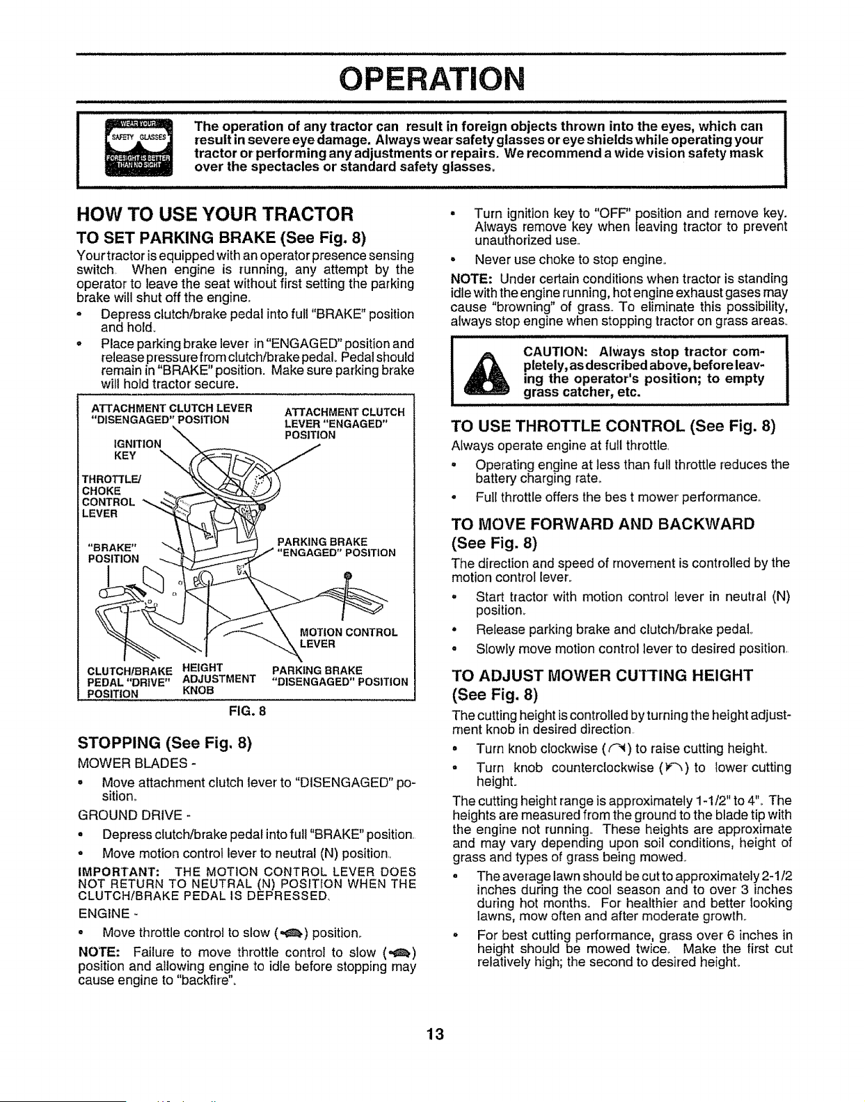
HOW TO USE YOUR TRACTOR
TO SET PARKING BRAKE (See Fig. 8)
Your tractor isequipped with an operator presence sensing
switch, When engine is running, any attempt by the
operator to leave the seat without first setting the parking
brake will shut off the engine.
- Depress clutchforake pedal into full "BRAKE" position
and hold.
. Place parking brake lever in "ENGAGED" position and
release pressure from clutch/brake pedal Pedal should
remain in "BRAKE" position. Make sure parking brake
will hold tractor secure.
ATTACHMENT CLUTCH LEVER
"DISENGAGED" POSITION
IGNITION
KEY
THROTTLE/
CHOKE
CONTROL
LEVER
ATTACHMENT CLUTCH
LEVER "ENGAGED"
POSITION
PARKING BRAKE
POSITION
MOTION CONTROL
LEVER
CLUTCH/BRAKE HEIGHT
PEDAL "DRIVE" ADJUSTMENT
POSITION KNOB
FIG. 8
PARKING BRAKE
"DISENGAGED" POSITION
STOPPING (See Fig, 8)
MOWER BLADES -
. Move attachment clutch lever to "DISENGAGED" po-
sition_
GROUND DRIVE -
o Depress clutch/brake pedal into full "BRAKE" position,
- Move motion control lever to neutral (N) position,
IMPORTANT: THE MOTION CONTROL LEVER DOES
NOT RETURN TO NEUTRAL (N) POSITION WHEN THE
CLUTCH/BRAKE PEDAL IS DEPRESSED,
ENGINE -
• Move throttle control to slow (,,_) position.
NOTE: Failure to move throttle control to slow (,,t_)
position and allowing engine to idle before stopping may
cause engine to "backfire",
• Turn ignition key to "OFF" position and remove key,
Always remove key when leaving tractor to prevent
unauthorized use,.
• Never use choke to stop engine.
NOTE: Under certain conditions when tractor is standing
idle with the engine running, hot engine exhaust gases may
cause "browning" of grass,. To eliminate this possibility,
always stop engine when stopping tractor on grass areas°
CAUTION: Always stop tractor com-
pletely, as described above, before leaw
ing the operator's position; to empty
grass catcher, etc.
TO USE THROTTLE CONTROL (See Fig. 8)
Afways operate engine at full throttle,
• Operating engine at less than full throttle reduces the
battery charging rate,,
• Full throttle offers the best mower performance,,
TO MOVE FORWARD AND BACKWARD
(See Fig, 8)
The direction and speed of rnovement is controlled by the
motion control lever,
= Start tractor with motion control lever in neutral (N)
position,
° Release parking brake and clutchlbrake pedal
• Slowly move motion control lever to desired position,
TO ADJUST MOWER CUTt'ING HEIGHT
(See Fig, 8)
The cutting height iscontrolled by turningthe height adjust-
rnent knob in desired direction.
° Turn knob clockwise ((",l) to raise cutting height.
- Turn knob counterclockwise (_"_,)to lower cutting
height.
The cutting height range is approximately 1-1/2" to 4"° The
heights are measured from the ground to the blade tip with
the engine not running_ These heights are approximate
and may vary depending upon soil conditions, height of
grass and types of grass being mowed,.
. The average lawn should be cutto approximately2-1/2
inches during the cool season and to over 3 inches
during hot months. For healthier and better looking
lawns, mow often and after moderate growth°
o For best cutting performance, grass over 6 inches in
height should be mowed twice_ Make the first cut
relatively high; the second to desired heighL
13
OPERATION
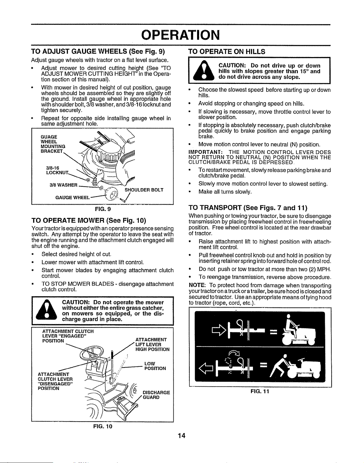
TO ADJUST GAUGE WHEELS (See Fig, 9)
Adjust gauge wheels with tractor on a flat level surface.
° Adjust mower to desired cutting height (See "TO
ADJUST MOWER CUTTING HEIGHT' in the Opera-
tion section of this manual).
• With mower in desired height of cut position, gauge
wheels should be assembled so they are slightly off
the ground° Install gauge wheel in appropriate hole
with shoulder bolt, 3/8 washer, and 3/8-16 locknutand
tighten securely_
• Repeat for opposite side installing gauge wheel in
same adjustment hole.
GUAGE
WHEEL
MOUNTING _
BRACKET. ._/_,
318 WASHER --.._
FIG. 9
SHOULDER BOLT
GAUGE
TO OPERATE MOWER (See Fig. 10)
Your tractor is equipped with an operator presence sensing
switch. Any attempt by the operator to leave the seat with
the engine running and the attachment clutch engaged will
shut off the engine.
• Select desired height of cut.
° Lower mower with attachment lift control
. Start mower blades by engaging attachment clutch
control.
• TO STOP MOWER BLADES - disengage attachment
clutch controt.
ATTACHMENT
LEVER
HIGH POSITION
.'j
.'," LOW
.'..L-----_POSfflON
IA
ATTACHMENT CLUTCH
LEVER "ENGAGED"
POSITION
DISCHARGE
"DISENGAGED"
POSITION
TO OPERATE ON HILLS
=NllIHllHllllu/=/l/ = =u/ = / =J / Ill J / l=UIUI/=
CAUTION: Do not drive up or down
hills with slopes greater than 15 ° and
do not drive across any slope,
o
°
°
i
Choose the slowest speed before starting up or down
hills,
Avoid stopping or changing speed on hills.
If slowing is necessary, move throttle control lever to
slower position°
If stopping is absolutely necessary, push clutch/brake
pedal quickly to brake position and engage parking
braker
• Move motion control lever to neutral (N) position
IMPORTANT: THE MOTION CONTROL LEVER DOES
NOT RETURN TO NEUTRAL (N) POSITION WHEN THE
CLUTCHtBRAKE PEDAL tS DEPRESSED
- To restart movement, slowly release parking brake and
clutch/brake pedal
• Slowly move motion control lever to slowest setting_
• Make all turns slowly°
TO TRANSPORT (See Figs, 7 and 111)
When pushingor towing you r tractor, be sure to disengage
transmission by placing freewheel control in freewheeling
position. Free wheel control is located at the rear drawbar
of tractor.
• Raise attachment lift to highest position with attach-
ment lift control
° Pull freewheel control knob out and hold in position by
inserting retainer spring into forward hole of control rod,
= Do not push or tow tractor at more than two (2) MPH.
• To reengage transmission, reverse above procedure.
NOTE: To protect hood from damage when transporting
your tractor on a truck or a trailer, be su re hood isclosed and
secured to tracton Use an appropriate means of tying hood
to tractor (rope, cord, etc).
FIG. 11
FIG. 10
14
OPERATION
BEFORE STARTING THE ENGINE
CHECK ENGINE OIL LEVEL (See Fig. 16)
• The engine inyourtractor has been shipped, from the
factory, already filled with summer weight oil,.
° Check engine oil with tractor on level ground_
° Unthread and remove oil fill cap/dipstick; wipe oil off.
Reinsert the dipstick into the tube and rest oil fill cap on
the tube. Do not thread the cap onto the tube. Remove
and read oil level If necessary, add oil until "FULU'
mark on dipstick is reached.. Do not overfill
° For cold weather operation you should change oil for
easier starting (See "OIL VISCOSITY CHART" in the
Customer Responsibilities section of this manual).
o To change engine oil, see the Customer' Responsibili-
ties section in this manual..
ADD GASOLINE
° Fill fue! tank. Use fresh, clean, regular unleaded
gasoline with a minimum of 87 octane., (Use of leaded
gasoline will increase carbon and lead oxide deposits
and reduce valve life),. Do not mix oil with gasoline.
Purchase fuel in quantities that can be used within 30
days to assure fuel freshness,.
IMPORTANT; WHEN OPERATING IN TEMPERATURES
BELOW32_F(0aC), USE FRESH, CLEAN WINTER GRADE
GASOLINE TO HELP INSURE GOOD COLD WEATHER
STARTING.
WARNING: Experience indicates that alcohol blended
fuels (called gasohot or using ethanol or' methanol) can
attract moisture which leads to separation and formation of
acids during storage.. Acidic gas can damage the fuel
system of an engine while in storage° To avoid engine
problems, the fuel system should be emptied before stor-
age of 30 days or longer. Drain the gas tank, start the
engine and let it run until the fuel lines and carburetor are
empty. Use fresh fuel next season. See Storage Instruc-
tions for additional information. Never use engine or
carburetor cleaner products in the fuel tank or pemlanent
damage may occur°
CAUTION: Fill to bottom of gas tank
filler' neck, Do not overfill. Wipe off any
spilled oil or fuel Do not store, spill or
use gasoline near an open flame,
TO START ENGINE (See Fig. 8)
When starting the engine for the first time or if the engine
has run out of fuel, it will take extra cranking time to move
fuel from the tank to the engine..
• Depress clutch/brake pedal and set parking brake.
. Place motion control lever in neutral (N) position_
• Move attachment clutch to "DISENGAGED" position°
o Move.throttle control to choke (N) position.,
Note: Before starting, read the warm and cold starting
procedures below.
• Insert keyinto ignition and turn keyclockwise to"START"
position and release key as soon as engine starts, Do
not run starter continuousfy for more than fifteen sec-
onds per minute_ If the engine does not start after
several attempts, move throttle control to fast (,,_)
position, wait a few minutes and try again_ If engine still
does not start, move the throttle control back to the
choke (1\1)position and retry,.
15
WARM WEATHER STARTING (50° F and above)
• When engine starts, move the throttle control to the fast
(,te_)position.
° The attachments and ground drive can nowbe used. if
the engine does not accept the load, restart the engine
and allow it to warm up for one minute using the choke
as described above.
COLD WEATHER STARTING ( 50° F and below)
° When engine starts, allow engine to run with the throttle
control in the choke (\]) position until the engine runs
roughly, then move thrott e control to fast (,¢_)position.,
This may require an engine warm-up period from
several seconds to several minutes, depending on the
temperature.
HYDROSTATIC TRANSMISSION WARM UP
= Before driving the unit in cold weather, the transmis-
sion should be warmed up as follows:
° Be sure the tractor is on level ground.
o Place the motion control lever' in neutraL.
Release the parking brake and let the clutch!brake
slowly return to operating position.
= Allow one minute for transmission to warm up..
This can be done during the engine warm up
period.
o The attachments can also be used duringthe engine
warm-upperiod afterthe transmission has been warmed
up.
NOTE: If at a high altitude (above 3000 feet) or in cold
temperatures (below 32 F) the carburetor fuel mixture may
need to be adjusted for best engine performance. See "TO
ADJUST CARBURETOR" in the Service and Adjustments
section of this manual..
PURGE TRANSMISSION
CAUTION: Never engage ordisengage
freewheel lever while the engine is run-
ning.
To ensure proper operation and performance, it is recom-
mended that the transmission be purged before operating
tractor for' the first tirne_ This procedure wil{ remove any
trapped air' insidethe transmission which may have devel-
oped during shipping of your tractor,.
IMPORTANT: SHOULD YOUR TRANSMISSION REQUIRE
REMOVAL FOR SERVICE OR REPLACEMENT, IT
SHOULD BE PURGED AFTER REINSTALLATION
BEFORE OPERATIN'G THE TRACTOR.
° Place tractor safely on Ievelsurface with engine off and
parking brake seL
o Disengage transmission by placing freewheel control
in freewheeling position (See "TO TRANSPORT" in
this section of manual).
° Sitting inthe tractor seat, start engine° After the engine
is running, move throttlecontrol to slow (.e!,) position.
With motion control lever inneutral (N) position, slowly
disengage clutch/brake pedal
o Move motion control lever to full forward position and
hold for five (5) seconds, Move lever to full reverse
position and hold for five (5) seconds° Repeat this
procedure three (3) times.
OPERATION
NOTE: Dudng thisprocedure there will be no movement of
drive wheels. The air is being removed from hydraulic dnve
system
= Move motion control lever to neutral (N) position_ Shut-
off engine and set parking brake°
° Engage transmission by placing freewheel control in
driving position (See "TO TRANSPORT" inthis section
of manual).
• Sitting in the tractor seat, start engine. After the engine
is running, move throttle control to half (1/2) speed.
With motion control lever in neutral (N) position, slowly
disengage clutch/brake pedal.
• Slowly move motion control lever forward, after the
tractor moves approximately five (5) feet, slowly move
motion control lever to reverse position° After the
tractor moves approximately five (5) feet return the
motion control leverto the neutral (N) position, Repeat
this procedure with the motion control lever three (3)
times.
• Your tractor is now purged and now ready for normal
operation,.
MOWING TIPS
° Tire chains cannot be used when the mower housing
is attached to tractor.
• Mower should be propedy leveled for best mowing
performance,. See 'q"O LEVEL MOWER HOUSING"in
the Service and Adjustments section of this manual.
• The left hand side of mower should be used for trim-
ming.
° Drive so that clippings are discharged onto the area
that has been cut. Have the cut area to the right of the
machine,. This will result in a more even distribution of
clippings and more uniform cutting.
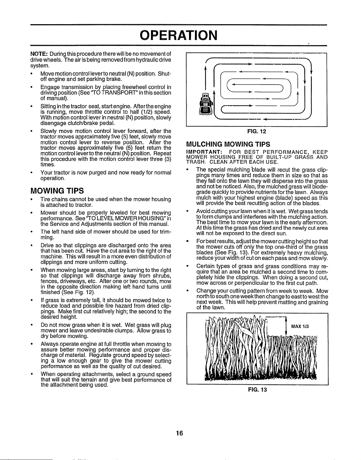
• When mowing large areas, start by turning to the right
so that clippings will discharge away from shrubs,
fences, driveways, etc. After one or two rounds, mow
in the opposite direction making left hand turns until
finished (See Fig. 12),.
• If grass is extremely tall, it should be mowed twice to
reduce load and possible fire hazard from dried clip-
dPings.Make first cut relatively high; the second to the
esired height..
- Do not mow grass when it is wet. Wet grass will plug
mower and leave undesirable clumps. Allow grass to
dry before mowing°
° Always operate engine at full throttle when mowing to
assure better mowing performance and proper dis-
charge of material Regulate ground speed by select-
ing a low enough gear to give the mower cutting
performance as well as the quality of cut desired°
° When operating attachments, select a ground speed
that will suit the terrain and give best performance of
the attachment being used.
F
1
¢:....
J]
FIG. 12
MULCHING MOWING TIPS
IMPORTANT: FOR BEST PERFORMANCE, KEEP
MOWER HOUSING FREE OF BUILT-UP GRASS AND
TRASH° CLEAN AFTER EACH USE.
° The special mulching blade will recut the grass clip-
pings many times and reduce them in size so that as
they fall onto the lawn they will disperse into the _rass
and not be noticed., Also, the mulched grass will bode-
grade quickly to provide nutrients for the lawm Always
mulch with your highest engine (blade) speed as this
will provide the best recutting action of the blades..
° Avoid cutting your lawn when it is wet.. Wet grass tends
to form clumps and interferes with the mulching action,.
The best time to mow your lawn is the early afternoom
At this time the grass has dried and the newly cut area
will not be exposed to the direct sun,.
° For best results, adjust the mowercutting height so that
the mower cuts off only the top one4hird of the grass
blades (See Fig. 13)o For extremely heavy mulching,
reduce your width of cut on each pass and mow slowly.
° Certain types of grass and grass conditions may re-
quire that an area be mulched a second time to com-
pletely hide the clipping& When doing a second Cut,
mow across or perpendicular to the first cut path..
° Change your cutting pattern from week to week. Mow
north to south one week then change to east to west the
next week. This will help prevent matting and graining
of the lawno
MAX 1/3
FIG. 13
16
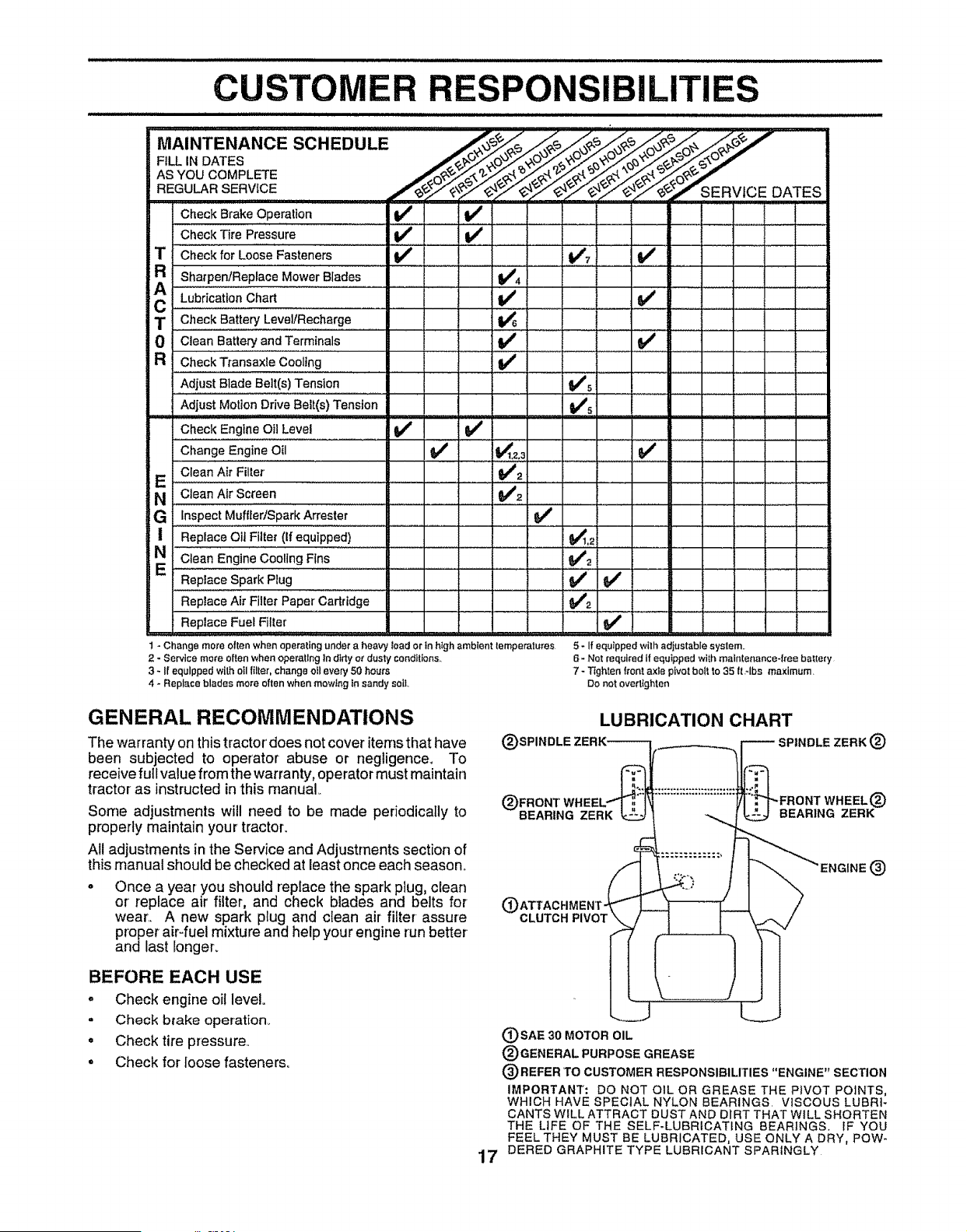
CU
IBILITIES
AS YOU COMPLETE
REGULARSERVtOE /_._"S ERVtCE DATES
Check Brake Operation ............V _' . . V # .......
Check Tire Pressure _ V v . V _ . . .
iT Check for Loose Fasteners I1_ !1_7
A ShatpenJReplace Mower Blades !_4
, ii i,o Cha ii............i........ v' v' , ,
T Check BatteryLevel/Recharge : _ : _ .............
0 Clean Battery and Terminals V e t_
R Check Transaxle Cooling I_
=
Adjust Blade Belt(s) Tension _5
Adjust Motion Drive Belt(s) Tension _/_
Check Engine Oil Level _ tf
Change Engine Oil 6#4 , ]_1,2,3 ......... 6#4 .....
'iF Clean Air Fillet' . . $/'2 ....................
N Clean Air Screen _2 ..................
_,G Inspect Muffler!spark Arrester _#'
| Replace Oil Filter (if equipped) $,'_1,2
NE €!eanEngineC°oilngFlns i I i i i¢Ii "
Replace Spark Plug 11/ t_ /
Replace Air Filler Paper' Cartridge 6#_'_
Replace Fuel Filter
1 - Change more often when operating under a heavy load or in htgh ambient temperatures
2 - Service mere often when operating In dirty or dusty conditions,,
3 - If equipped with oil filter, change oil every 50 hours
4 - Replace blades more often when mowing in sandy sell.
5 - If equipped with adjustable system,,
6 - Not required if equipped with mainlenance-free batlety
7 - Tighten front axle pivot boil to 35 tt.qbs maximum.
Do net overtighten
GENERAL RECOMMENDATIONS
The warranty on this tractor' does not cover items that have
been subjected to operator abuse or negligence° To
receive full value from the warranty, operator must maintain
tractor as instructed in this manual.
Some adjustments will need to be made periodically to
properly maintain your tractor.
All adjustments in the Service and Adjustments section of
this manual should be checked at least once each season.
Once a year you should replace the spark plug, clean
or replace air filter, and check blades and belts for
wear'.. A new spark plug and clean air filter-assure
proper air4uel mixture and help your engine run better
andlast Ionger,
BEFORE EACH USE
= Check engine oil level.
• Check blake operation°
• Check tire pressure,
° Check for loose fasteners,
17
LUBRICATION CHART
(_SPINDLE ZERK_ _ -- SPINDLE ZERK(_)
®SAE 30 MOTOR OIL
®GENERAL PURPOSE GREASE
I_--FRONTWHEEL®
-_ BEARINGZERK
LI
®REFER TO CUSTOMER RESPONSIBILITIES "ENGINE" SECTION
IMPORTANT: DO NOT OiL OR GREASE THE PIVOT POINTS,
WHICH HAVE SPECIAL NYLON BEARINGS. VISCOUS LUBRI-
CANTS WILL ATTRACT DUST AND DIRT THAT WILL SHORTEN
THE LIFE OF THE SELF_LUBRICATING BEARINGS. IF YOU
FEEL THEY MUST BE LUBRICATED, USE ONLY A DRY, POW-
DERED GRAPHITE TYPE LUBRICANT SPARINGLY
ME SIBILITIES
TRACTOR
AIways observe safety rules when performingany mainte-
nance,
BRAKE OPERATION
If tractor requires more than six (6) feet stopping distance
at high speed in highest gear, then brake must be adjusted.
(See "TO ADJUST BRAKE" in the Service and Adjust-
ments section of this manual).
TIRES
• Maintain proper air pressure in all tiros (See "PROD-
UCT SPECIFICATIONS" on page 3 of this manual),
• Keep tires free of gasoline, oil, or insect control chemi-
cals which can harm rubber,
• Avoid stumps, stones, deep ruts, sharp objects and
other hazards that may cause tire damage.
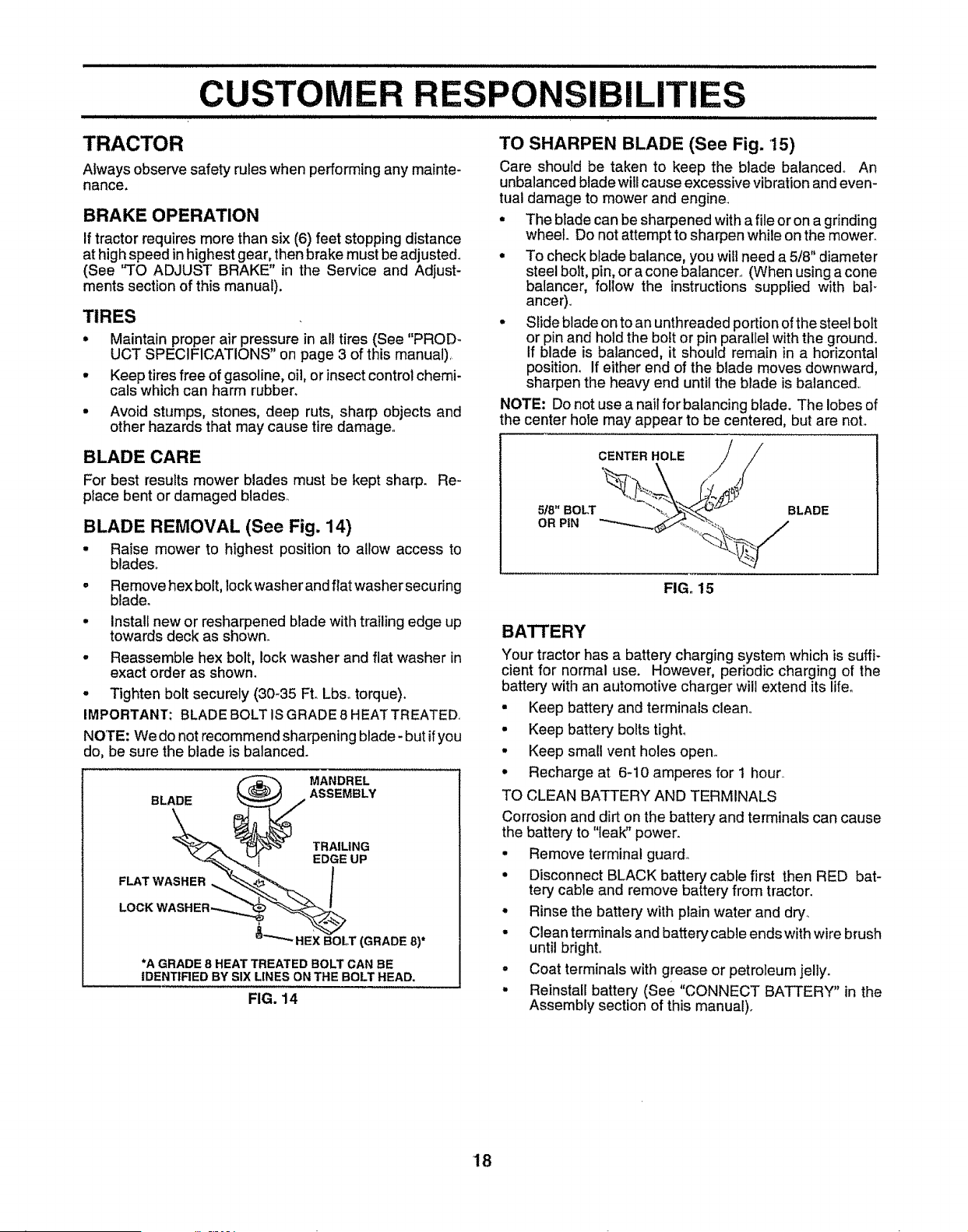
BLADE CARE
For best results mower blades must be kept sharp. Re-
place bent or damaged blades.
BLADE REMOVAL (See Fig. 14)
. Raise mower to highest position to allow access to
blades.
° Remove hex bolt, lockwasher andflat washersecuring
blade.
• Install new or resharpened blade with trailing edge up
towards deck as shown.
° Reassemble hex bolt, lockwasher and fiat washer in
exact order as shown.
° Tighten bolt securely (30-35 Ft. Lbs.. torque).
IMPORTANT: BLADE BOLT IS GRADE 8 HEATTREATED.
NOTE: We do not recommend sharpening blade - but ifyou
do, be sure the blade is balanced.
__ MANDREL
BLADE ASSEMBLY
TRAILING
EDGE UP
FLAT WASHER ,_ _,_'_,,,_ I
LOCK WASH ER -,..,,._
HEX BOLT (GRADE 8)*
*A GRADE 8 HEAT TREATED BOLT CAN BE
IDENTIRED BY SIX LINES ON THE BOLT HEAD.
FIG. 14
TO SHARPEN BLADE (See Fig. '15)
Care should be taken to keep the blade balanced. An
unbalanced blade will cause excessive vibration and even-
tual damage to mower and engine.
• The blade can be sharpened with a file or on a grinding
wheel. Do not attempt to sharpen while on the mower.
• To check blade balance, you will need a 5/8" diameter
steel bolt, pin, or a cone balancer. (When using a cone
balancer, follow the instructions supplied with bal-
anGer)°
• Slide blade onto an unthreaded portion ofthe steel bolt
or pin and hold the bolt or pin parallel with the ground.
If blade is balanced, it should remain in a horizontal
position, I[ either end of the blade moves downward,
sharpen the heavy end until the blade is balanced.
NOTE: Do not use a nail for balancing blade. The lobes of
the center hole may appear to be centered, but are not°
CENTER HOLE /
FIG. 15
BATTERY
Your tractor has a batterycharging system which is suffi-
cient for normal use. However, periodic charging of the
battery with an automotive charger will extend its lifeo
• Keep battery and terminals clean,,
• Keep battery bolts tight°
, Keep small vent holes open.
• Recharge at 6-10 amperes for i hour
TO CLEAN BATTERY AND TERMINALS
Corrosion and dirt on the battery' and terminals can cause
the battery to "leak" power.
• Remove terminal guard.
• Disconnect BLACK battery cable first then RED bat-
tery cable and remove battery from tractor.
° Rinse the battery with plain water and dry_
- Clean terminals and battery cable endswith wire brush
until bright°
° Coat terminals with grease or petroleum jelly.
- Reinstall battery (see "CONNECT BATTERY" in the
Assembly section of this manual).
18
CUSTOMER ILITIES
TRANSAXLE COOLING
The fan and cooling fins of transmission should be kept
clean to assure proper cooling.
Do not attempt to clean fan or transmission while engine is
running or while the transmission is hot.
= Inspect cooling fan to be sure fan blades are intactand
clean.
° Inspect cooling fins for dirt, grass clippings and other
materials. To prevent damage to seals, do not use
compressed air or high pressure sprayer to clean
coohngfins.
TRANSAXLE PUMP FLUID
The transaxle was sealed at the factory and fluid mainte-
nance isnot requiredfor'the life ofthe transaxle. Shouldthe
transaxle ever leak or require servicing,contactyour near-
est authorized service center/department.
V-BELTS
CheckV-belts for deteriorationand wear after 100 hoursof
operation and replace if necessary. The belts are not
adjustable. Replace belts if they begin to slip from wear.
ENGINE
LUBRICATION
Only use high quality detergent oil rated with API service
classification SF, SG or SH. Select the oil's SAE viscosity
grade according to your expected operating temperature.
SAE VISCOSITY GRADES
ll}lllT_ |1
4ii m limm t
°F -20" O" 30 ° 32 ° 40 ° 60" 80" 100 =
°c -3o" -2o' -t_)o o° lo" 2o" 30, ,to'
TEMPERATURE RANGE ANTICIPATED BEFORE NEXT OiL CHANGE
FIG. 16
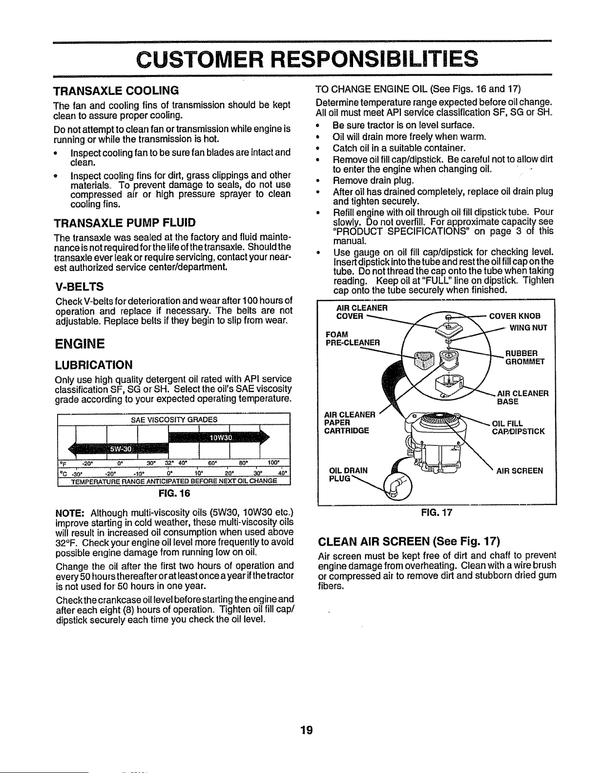
TO CHANGE ENGINE OIL (See Figs. 16 and 17)
Determine temperature mangeexpected before oilchange.
All oil must meet API service classification SF, SG or SH.
° Be sure tractor is on level surface.
° Oil will drain more freely when warm°
° Catch oil in a suitable container.
° Remove oil fill cap/dipstick. Be careful not to allow dirt
to enter the engine when changing oil • •
° Remove drain plugo
= After oil has drained completely, replace oil drain plug
and tighten securely.
= Refill engine with oil through oil fill dipstick tube. Pour
slowly. Do not overfill. For approximate capacity see
"PRODUCT SPECIFICATIONS" on page 3 of this
manual
• Use gauge on oil fill cap!dipstick for checking level.
insert dipstick into the tube and rest the oil fill cap on the
tube. Do not thread the cap onto the tube when taking
reading. Keep oil at FULL line on dipstick. Tighten
cap onto the tube securely when finished.
AIR CLEANER
COVER
FOAM
PRE-CLEANER
COVER KNOB
WING NUT
RUBBER
CLEANER
BASE
AIR CLEANER
PAPER L FILL
CARTRIDGE CAP/DIPSTICK
AIR SCREEN
NOTE: Although multi-viscosity oils (5W30, 10W30 etc°)
improve starting in cold weather, these multi-viscosity oils
will result in increased oil consumption when used above
32°F, Check your engine oil level more frequently to avoid
possible engine damage from running low on oil,
Change the oil after the first two hours of operation and
every 50 hours thereafter or at least once a year if thetractor
is not used for 50 hours in one year.
Checkthecrankcase oil level before starting the engine and
after each eight (8) hours of operation. Tighten oil fill cap/
dipstick securely each time you check the oi! level.
FIG, 17
CLEAN AIR SCREEN (See Fig. 17)
Air screen must be kept free of dirt and chaff to prevent
engine damage from overheating. Clean with a wire brush
or compressed air to remove dirt and stubborn dried gum
fibers.
19
CUSTOMER RESPONSIBILITIES
AIR FILTER (See Fig. 17)
Your engine will not run properly using a dirty air filter°
Clean the foam pre-cleaner after every 25 hours of opera-
tion or every season. Service paper cartridge every I00
hours of operation or every season, whichever occurs first.
Service air cleaner more often under dusty conditions.
• Remove knob and cover°
• Remove wing nut and air cleaner from base.
TO SERVICE PRE-CLEANER
• Slide foam pre-cleaner off cartridge.
° Wash it in liquid detergent and water,
° Squeeze it dry in a clean cloth. Allow it to dry,
• Saturate it in engine oil. Wrap it in clean, absorbent
cloth and squeeze to remove excess oil.
TO SERVICE CARTRIDGE
• Replace a dirty, bent, or damaged cartddgeo
NOTE: Do not wash the paper cartridge or use pressurized
air, as this will damage the cartridge.
• Reinstall the pre-cleaner (cleaned and oiled) over the
paper cartridge.
° Reassemble air cleaner, wing nut, cover and tighten
knob securely.
CLEAN AIR INTAKE/COOLING AREAS
To insure proper cooling, make sure the grass screen,
cooling fins, and other external surfaces of the engine are
kept clean at all times_
Every 100 hours of operation (more often under extremely
dusty, dirty conditions), remove the blower housing and
other cooling shrouds. Clean the cooling fins and external
surfaces as necessary. Make sure the cooling shrouds are
reinstalled_
NOTE: Operating the engine witha blocked grass screen,
dirty or plugged cooling fins, and/or cooling shrouds re-
moved will cause engine damage due to overheating_
ENGINE OIL FILTER (See Fig. 18)
Replace the engine oil filter every season or every other oil
change if the tractor is used more than 100 hours in one
year°
• Drain oil from engine crankcase (See 'q_O CHANGE
ENGINE OIU' in this section of this manual, through
step remove drain plug)o
• Remove oil filter and wipe off filter adapter_
• Apply a thin coating of new engine oil to the rubber
gasket on replacement oil filter.
• Install replacement oil filter on filter adapter. Turn oil
filter clockwise until rubber gasket contacts the filter
adapter, then tighten filter an additional 1/2 turn.
• Fill crankcase with new oil (See 'q'O CHANGE EN-
GINE OIL in this section of this manual). For approxi-
mate capacity see "PRODUCT SPECIFICATIONS" on
page 3 of this manual.
• Start the engine and check for oil leaks. Correct any
leaks before placing engine into full operation.
2O
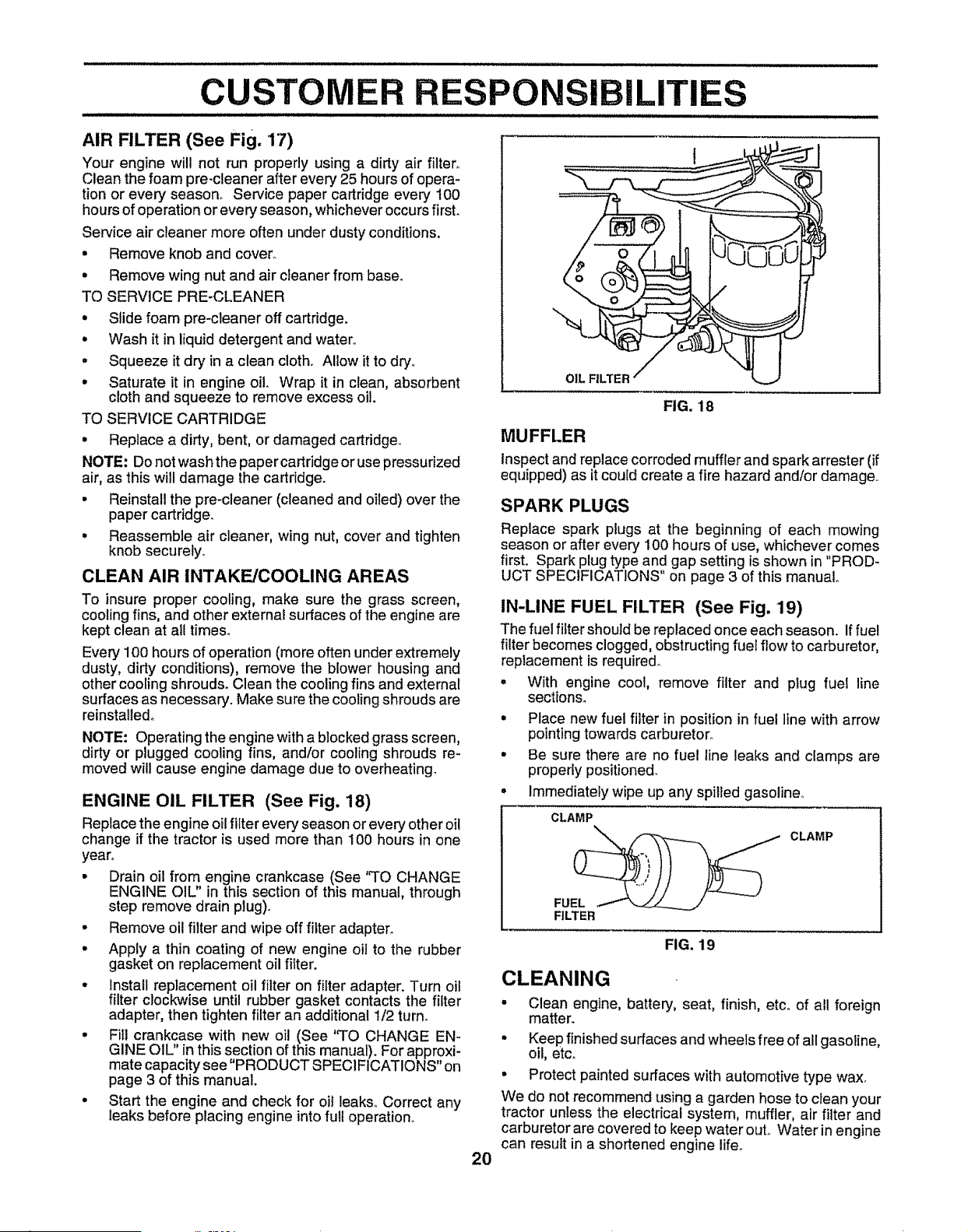
OIL FILTER /
FIG. 18
MUFFLER
Inspectand replace corroded muffler and spark arrester (if
equipped) as it could create a fire hazard and/or damage
SPARK PLUGS
Replace spark plugs at the beginning of each mowing
season or after every 100 hours of use, whichever comes
first. Spark plug type and gap setting is shown in "PROD-
UCT SPECIFICATIONS" on page 3 of this manual.
IN-LINE FUEL FILTER (See Fig. 19)
The fuel _ter should be replaced once each season. Iffue!
filter becomes clogged, obstructing fuel flow to carburetor,
replacement is required°
• With engine cool, remove filter and plug fuel line
sections.
• Place new fuel _ter in position in fuel line with arrow
pointing towards carburetor°
• Be sure there are no fuel line leaks and clamps are
properly positioned.
° Immediately wipe up any spilled gasoline°
CLAMP
FU____ / CLAMP
FILTER
FIG. 19
CLEANING
- Clean engine, battery, seat, finish, etco of all foreign
matter.
• Keep finished surfaces and wheels free of all gasoline,
oil, etc.
° Protect painted surfaces with automotive type wax.
We do not recommend using a garden hose to clean your
tractor unless the electrical system, muffler, air filter and
carburetor are covered to keep water ouL Water in engine
can result in a shortened engine lifeo
SERVICE AND ADJUSTMENTS
........................................................................ _ ,,lllll ,lll.ll .
CAUTION: BEFORE PERFORMING ANY SERVICE OR ADJUSTMENTS:
* Depress clutch/brake pedal fully and set parking brake,
i Place motion control lever in neutral (N) position.
Q
Place attachment clutch in "DISENGAGED" position.
Turn ignition key "OFF" and remove key°
Make sure the blades and all moving parts have completely stopped°
Disconnect spark plug wire from spark plug and place wire where it cannot come in contact with
plug.
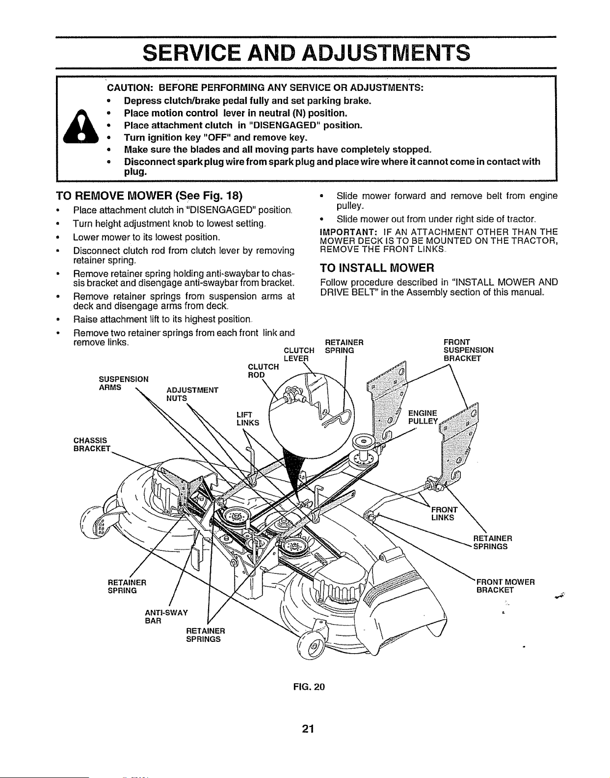
TO REMOVE MOWER (See Fig. 18)
• Place attachment clutch in "DISENGAGED" position
• Turn height adjustment knob to lowestsetting.,
• Lower mower to its lowest position_
° Disconnect clutch rod from clutch lever' by removing
retainer spring.
• Remove retainer spring holding anti-swaybar to chas-
sis bracket and disengage anti-swaybar from bracket.
° Remove retainer springs from suspension arms at
deck and disengage arms from deck.
° Raise attachment lift to its highest position..
• Remove two retainer' springs from each front link and
remove links.
SUSPENSION
ARMS
ADJUSTMENT
NUTS
CLUTCH
ROD
LIFT
LINKS
° Slide mower forward and remove belt from engine
pulley.
o Slide mower out from under right side of tractor.
IMPORTANT: IF AN ATTACHMENT OTHER THAN THE
MOWER DECK IS TO BE MOUNTED ON THE TRACTOR,
REMOVE THE FRONT LINKS..
TO INSTALL MOWER
Follow procedure described in "INSTALL MOWER AND
DRIVE BELT" in the Assembly section of this manual
RETAINER FRONT
CLUTCH SPRING SUSPENS!ON
LEVER BRACKET
ENGINE
CHASSIS
LINKS
RETAINER
SPRINGS
RETAINER
SPRING
ANTI-SWAY
BAR
RETAINER
SPRINGS
MOWER
BRACKET
FIG. 20
21
SERVICE AND ADJUSTMENTS
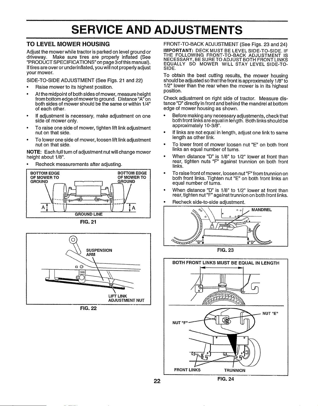
TO LEVEL MOWER HOUSING
.........i....................................
Adjust the mower while tractor is parked on level ground or
driveway_ Make sure tires are properly inflated (See
"PRODUCT SPECIFICATIONS" on page 3 of this manua 0.
If tires are over or underinflated, you will not properly adjust
your mower.
SIDE-TO-SIDE ADJUSTMENT (See Figs, 21 and 22)
• Raise mower to its highest position_
° At the midpoint of both sides of mower, measure height
from bottom edge of mower to ground° Distance "A" on
both sides of mower should be the same or within I/4"
of each other,
• If adjustment is necessary, make adjustment on one
side of mower only.
° To raise one side of mower, tighten lift link adjustment
nut on that side,
° To Iower one side of mower, loosen liftlink adjustment
nut on that side°
NOTE: Each full turn of adjustment nut wilt change mower
height about 1/8'L
• Recheck measurements after adjusting..
BOTTOM EDGE BOTTOM EDGE
OF MOWER TO OF MOWER TO
GROUND LINE
FIG. 21
FRONT-TO-BACK ADJUSTMENT (See Figs° 23 and 24)
IMPORTANT: DECK MUST BE LEVEL SIDE-TO-SIDEr IF
THE FOLLOWING FRONT-TO-BACK ADJUSTMENT IS
NECESSARY, BE SURE TO ADJUST BOTH FRONT LINKS
EQUALLY SO MOWER WILL STAY LEVEL SIDE-TO-
SIDE.
To obtain the best cutting results, the mower housing
should be adjusted so that the front isapproximately 1/8" to
1/2" lower than the rear when the mower is in its highest
position.
Check adjustment on right side of tractor. Measure dis-
tance "D" directly infront and behind the mandre! at bottom
edge of mower housing as shown.
• Before making any necessary adjustments, check that
both front links are equal in length,. Both links should be
approximately 10-3/8".
• If links are not equal in length, adjust one link to same
length as other link.
• To lower front of mower loosen nut "E" on both front
links an equal number of turns,,
• When distance "D" is 1/8" to 1/2" lower at front than
rear, tighten nuts "F" against trunnion on both front
links.
- To raise front of mower, loosen nut"F" from trunnion on
both front links. Tighten nut "E" on both front links an
equal number of turns.
° When distance "D" is t/8" to 1/2" lower at front than
rear, tighten nut"F" against trunnion on both front links,.
• Recheck side-to-side adjustment,.
MANDREL
SUSPENSION
ARM
FIG. 22
LIFT LINK
ADJUSTMENT NUT
22
FIG. 23
BOTH FRONT LINKS MUST BE EQUAL IN LENGTH
NUT "E"
NUT
FRONT LINKS
TRUNNION
FIG. 24
SERVICE AND ADJUSTMENTS
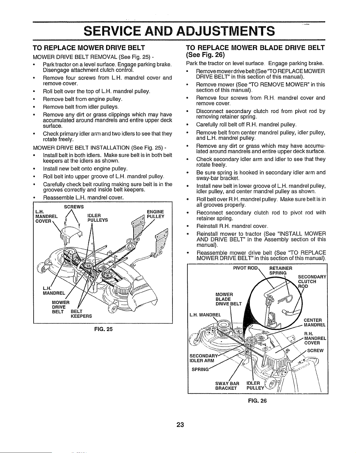
TO REPLACE MOWER DRIVE BELT
MOWER DRIVE BELT REMOVAL (See Fig° 25) -
• Park tractor on a level surface. Engage parking brake.,
Disengage attachment clutch control
• Remove four screws from L,,H. mandrel cover and
remove cover'.
• Roll belt over the top of L.H. mandrel pulley.
° Remove belt from engine pulley_
° Remove belt from idler pulleys,
o Remove any dirt or grass clippings which may have
accumulated around mandrels and entire upper deck
surface_
° Check primary idler' arm and two idlersto see that they
rotate freely.
MOWER DRIVE BELT INSTALLATION (See Fig. 25) -
= Install belt in both idlers, Make sure belt is in both belt
keepers at the idlers as shown.
• Install new belt onto engine pulley.
° Roll belt into upper groove of L,.H,mandrel pulley,.
° Carefully check belt routing making sure belt is in the
grooves correctly and inside belt keepers_
Reassemble L.H. mandrel cover'.
SCREWS
L.H. ENGINE
MANDREL IDLER PULLEY
PULLEYS
MANDREL
MOWER
DRIVE
BELT BELT
KEEPERS
FIG. 25
TO REPLACE MOWER BLADE DRIVE BELT
(See Fig. 26)
Park the tractor on level surface Engage parking brake.
• Remove mower'drive belt (See'`TO REPLACE MOWER
DRIVE BELT" in this section of this manual),
• Remove mower (See "TO REMOVE MOWER" in this
section of this rnanual)_
° Remove four screws from R.H mandrel cover and
remove cover°
° Disconnect secondary clutch rod from pivot rod by
removing retainer spring.
= Carefully roll belt off R_H. mandrel pulley,,
= Remove belt frorn center' mandrel pulley, idlerpulley,
and L.H. mandrel pulley°
° Remove any dirt or grass which may have accumu-
lated around mandrels and entire upper deck surface.
° Check secondary idler arm and idler to see that they
rotatefreeiy_
° Be sure spring is hooked in secondary idler arm and
sway-bar bracket°
° install new belt in lower groove of LHo mandrel pulley,
idler pulley, and center mandrel pulley as shown_
o Rol! belt over RH_ mandrel pulley_ Make sure belt is in
all grooves properly,.
= Reconnect secondary clutch rod to pivot rod with
retainer spring°
o Reinstall R.H. mandrel cover..
° Reinstall mower-to tractor (See "INSTALL MOWER
AND DRIVE BELT" in the Assembly section of this
manual),,
° Reassemble mower drive belt (See "TO REPLACE
MOWER DRIVE BELT in this section of this manual),
PIVOT ROD RETAINER I
SPRING
]
SECONDARY
CLUTCH
ROD
MOWER
BLADE
DRIVE BELT
LoHoMANDREL
SPRING
SWAY BAR
BRACKET
IDLER(
PULLEY
FIG. 26
23
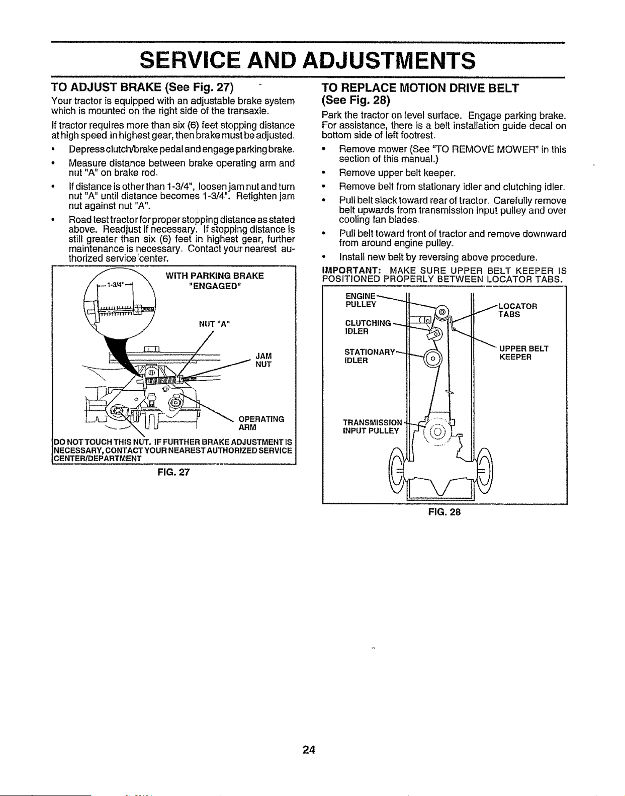
o
o
SERVICE AND ADJUSTMENTS
,,==,,U,=N=,,/J,===W,=,,l=l=l===lH,l=,l=lH ==ill=ill=l= ill ,'l ,ll I ill I
TO REPLACE MOTION DRIVE BELT
(See Fig. 28)
Park the tractor on level surface° Engage parking brake.
For assistance, there is a belt installation guide decal on
bottom side of leftfootrest.,
• Remove mower (See "TO REMOVE MOWER" in this
section of this manual.)
• Remove upper belt keeper°
• Remove belt from stationary idlerand clutching idler,
- Pull belt slack toward rear of tractor. Carefully remove
belt upwards from transmission input pulley and over
cooling fan blades,
= Pull belt toward front of tractor and remove downward
from around engine pulley,,
• Install new belt by reversing above procedure,
IMPORTANT: MAKE SURE UPPER BELT KEEPER IS
POSITIONED PROPERLY BETWEEN LOCATOR TABS.
TO ADJUST BRAKE (See Fig. 27)
Your tractor is equipped with an adjustable brake system
which is mounted on the right side of the transaxleo
If tractor requires more than six (6) feet stopping distance
at high speed in highest gear, then brake must be adjusted°
• Depress clutch/brake pedal and engage parkingbrake°
Measure distance between brake operating arm and
nut "A" on brake rod°
Ifdistance isother than t-3/4", loosen jam nut and turn
nut "A" until distance becomes 1o3/4". Retighten jam
nut against nut "A".
Road test tractor for properstopping distance as stated
above. Readjust if necessary. If stopping distance is
still greater than six (6) feet in highest gear, further
maintenance is necessary,. Contact your nearest au-
thorized service _center.
WITH PARKING BRAKE
"ENGAGED"
JAM
NUT
OPERATING
ARM
DO NOT TOUCH THIS NUT. IF FURTHER BRAKE ADJUSTMENT IS
NECESSARY, CONTACT YOUR NEAREST AUTHORIZED SERVICE
CENTER/DEPARTMENT
FIG. 27
PULLEY
TABS
IDLER
BELT
IDLER KEEPER
TRANSMISSION"
INPUT PULLEY
FIG. 28
24
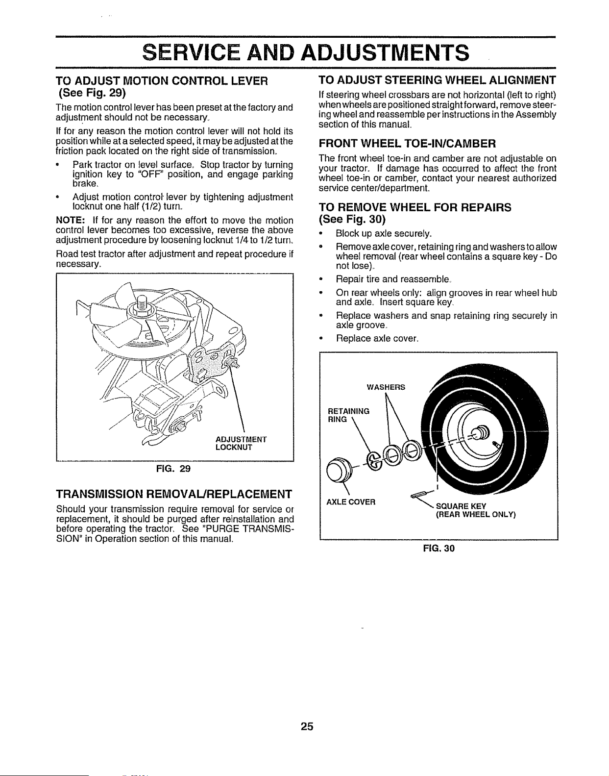
'"'I"HI'"UlN"H"I'"I"HI'HII'""1HHIIIlll,l,II,, I " IJ
SERVICE AND ADJUSTMENTS
'JIIUI'I'III'II"II"'IUHHI/"""I'HI'UI'U''/ J J/=''=='=' U' 'Hi= 1'11'
TO ADJUST MOTION CONTROL LEVER TO ADJUST STEERING WHEEL ALIGNMENT
(See Fig. 29)
The motion control lever has been preset at thefactory and
adjustment should not be necessary.
If for any reason the motion control lever will not hold its
position while at a selected speed, it may be adjusted at the
friction pack located on the right side of transmission..
• Park tractor on level surface_ Stop tractor by turning
ignition key to "OFF" position, and engage parking
brake.
= Adjust motion control-lever by tighteningadjustment
Iocknut one half (1/2) turn°
NOTE: If for any reason the effort to move the motion
control lever becomes too excessive, reverse the above
adjustment procedure by loosening Iocknut 1/4 to 1/2 turn°
Road test tractor after adjustment and repeat procedure if
necessary_
ADJUSTMENT
LOCKNUT
FIG. 29
TRANSMISSION REMOVAL/REPLACEMENT
Should your' transmission require removal for service or
replacement, it should be purged after reinstaHation and
before operating the tractor', See "PURGE TRANSMIS-
SION" in Operation section of this manual°
If steering wheel crossbars are not horizontal (left to right)
when wheels are positioned straightforward, remove steer'-
ing wheel and reassemble per instructionsin the Assembly
section of this manual
FRONT WHEEL TOE-IN/CAMBER
The front wheel toe-in and camber are not adjustable on
your tractor. If damage has occurred to affect the front
wheel toe-in or camber, contact your nearest authorized
service center/department.
TO REMOVE WHEEL FOR REPAIRS
(See Fig. 30)
* Block up axle securely°
o Remove axle cover, retaining ring and washersto allow
wheel removal (rear wheel contains a square key - Do
not lose)..
° Repair tire and reassemble.
- On rear wheels only: align grooves in rear wheel hub
and axleo Insert square key..
o Replace washers and snap retaining ring securely in
axle groove.
o Replace axle cover_
WASHERS
RETAINING
RING
AXLE COVER
!
_ SQUARE KEY
(REAR WHEEL ONLY)
FIG. 30
25
SERVICE AND ADJUSTMENTS
TO START ENGINE WITH A WEAK BA'n'ERY
(See Fig, 32)
CAUTION: Lead-acid batteries gener-
ateexplosive gases. Keepsparks, flame
and smoking materials away from bat-
teries. Always wear eye protection
when around batteries.
If your battery is too weak to start the engine, it should be
recharged, If "jumper cables" are used for emergency
starting, follow this procedure:
IMPORTANT: YOUR TRACTOR IS EQUIPPED WITH A t2
VOLT NEGATIVE GROUNDED SYSTEM° THE OTHER
VEHICLE MUST ALSO BE A 12 VOLT NEGATIVE
GROUNDED SYSTEM. DO NOT USE YOUR TRACTOR
BATTERY TO START OTHER VEHICLES_
TO ATTACH JUMPER CABLES -
• Connect each end of the RED cable to the POSITIVE
(+) terminal of each battery, taking care not to short
against chassis_
• Connect one end of the BLACK cable to the NEGA-
TIVE (-) terminal of fully charged battery°
° Connect the other end of the BLACK cable to good
CHASSIS GROUND, away from fuel tank and battery.
TO REMOVE CABLES, REVERSE ORDER -
• BLACK cable first from chassis and then from the fully
charged battery_
• RED cable last from both batteries.
"POSITIVE" (+) "NEGATIVE" (-)
LH, PANEL
BOLT
TO REPLACE HEADLIGHT BULB
• Raise hood.
° Pull bulb holder out of the hole in the backside of the
grill.
° Replace bulb in holder and push bulb holder securely
back into the hole in the backside of the grill.
• Close hood.
INTERLOCKS AND RELAYS
Loose or damaged wiring may cause your tractor to run
poorly, stop running, or prevent it from starting.
° Check wiring. See electrical wiring diagram in the
Repair Parts section of this manual.
TO REPLACE FUSE
Replace with 30 amp automotive-type plug-in fuse. The
fuse holder is located behind the dash.
TO REMOVE HOOD AND GRILL ASSEMBLY
(See Fig. 33)
• Raise hood°
° Unsnap headlight wire connector.
- Stand infront of tractor. Grasp hood at sides, tilt toward
engine and lift off of tractor_
° To replace, reverse above procedures.
HOOD
HEADLIGHT
WIRE
CONNECTOR
FIG. 33
FIG. 32
26
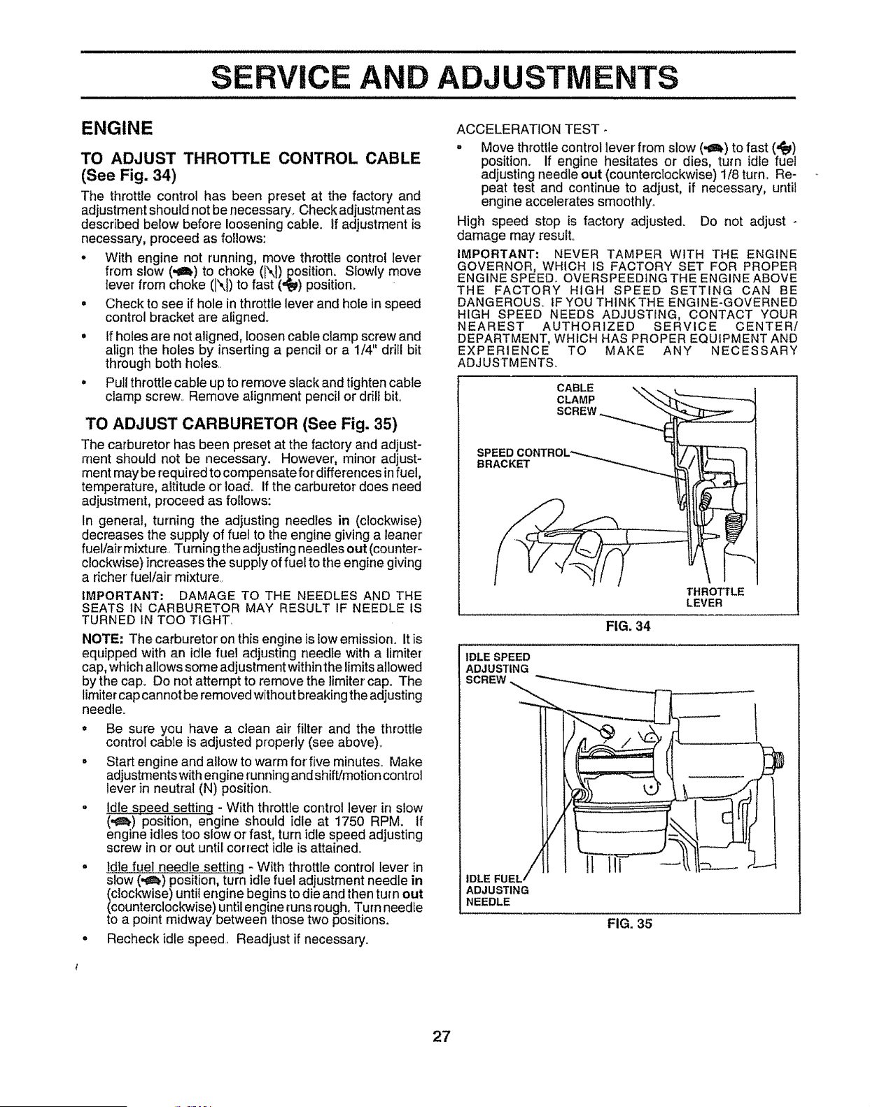
SERVICE AND ADJUSTMENTS
ENGINE
TO ADJUST THROTTLE CONTROL CABLE
(See Fig. 34)
The throttle control has been preset at the factory and
adjustment should not be necessary. Check adjustment as
described below before loosening cable° tf adjustment is
necessary, proceed as follows:
° With engine not running, move throttle control lever
from slow (.€_) to choke (N) position_Slowly move
lever from choke (1\1)to fast (,_) position.
• Check to see if hole in throttle lever and hole in speed
control bracket are aligned.,
= If holes are not aligned, _oosencable clamp screw and
align the holes by insertinga pencil or a 1/4" drill bit
through both holes,.
° Pu]i throttle cable up to remove slack and tighten cable
clamp screw,, Remove alignment pencil or drill bit.
TO ADJUST CARBURETOR (See Fig. 35)
The carburetor has been preset at the factory and adjust-
ment should not be necessary. However, minor adjust-
ment may be required to compensate for differences in fuel,
temperature, altitude or load,, If the carburetordoes need
adjustment, proceed as follows:
In general, turning the adjusting needles in (clockwise)
decreases the supply of fuel to the engine givinga leaner
fuel/air mixture, Turningthe adjusting needlesout (counter-
clockwise)increases the supply of fuel to the engine giving
a richer fuel/air mixture,
IMPORTANT: DAMAGE TO THE NEEDLES AND THE
SEATS IN CARBURETOR MAY RESULT IF NEEDLE IS
TURNED IN TOO TIGHT_
NOTE: The carburetor on this engine is tow ernissiono It is
equipped with an idle fuel adjusting needte with a limiter
cap, which allows some adjustment within the limits allowed
by the cap. Do not attempt to remove the limiter cap= The
limitercap cannot be removed without breaking the adjusting
needle.
° Be sure you have a clean air filter and the throttle
control cable is adjusted properly (see above)_
• Start engine and allow to warm for five minutes,. Make
adjustments with engine running and shift/motion control
lever in neutral (N) position.
° ldte speed setting - With throttle control lever in slow
(._) position, engine should idle at 1750 RPM. If
engine idles too slow OH'fast, turn idle speed adjusting
screw in or out until correct idle is attained°
. Idle fuel needle setting - With throttle control lever in
slow (.¢!,) position,turn idle fuel adjustment needle in
clockwise) until engine begins to die and then turn out
counterclockwise) until engine runs rough. Turn needle
o a point midway between those two positions.
o Recheck idle speed, Readjust if necessary.
ACCELERATION TEST-
. Move throttle control lever from slow (.¢!.) to fast (,_)
position. If engine hesitates or dies, turn idle fuel
adjusting needle out (counterclockwise) 1/8 turn, Re-
peat test and continue to adjust, if necessary, until
engine accelerates smoothly..
High speed stop is factory adjusted° Do not adjust -
damage may result°
IMPORTANT: NEVER TAMPER WITH THE ENGINE
GOVERNOR, WHICH IS FACTORY SET FOR PROPER
ENGINE SPEED.. OVERSPEEDtNG THE ENGINE ABOVE
THE FACTORY HIGH SPEED SETTING CAN BE
DANGEROUS. IF YOU THINK THE ENGINE-GOVERNED
HIGH SPEED NEEDS ADJUSTING, CONTACT YOUR
NEAREST AUTHORIZED SERVICE CENTER!
DEPARTMENT, WHICH HAS PROPER EQUIPMENT AND
EXPERIENCE TO MAKE ANY NECESSARY
ADJUSTMENTS..
CABLE
CLAMP
SCREW
SPEED
BRACKET
FIG. 34
THROTTLE
LEVER
IDLE SPEED
ADJUSTING
IDLE FUEL,
ADJUSTING
NEEDLE
FIG. 35
27
STORAGE
Immediately prepare your tractor for storage at the end of
the season or if the tractor will not be used for 30 days or
more.
CAUTION: Never store the tractor with
gasoline in the tank inside a building
where fumes may reach an open flame
or spark. Allow the engine to cool
before storing in any enclosure,
/ 11/,1Jl_ ;:
TRACTOR
Remove mower from tractor for winter storage_ When
mower is to be stored for a period of time, clean it thor-
oughly, remove all dirt, grease, leaves, etc. Store in a
clean, dry area,
• Clean entire tractor (See "CLEANING" in the Customer
Responsibilities section of this manual)°
• Inspect and replace belts, if necessary (See belt re-
placement instructionsin the Service and Adjustments
section of this manual).
• Lubricate as shown in the Customer Responsibilities
section of this manual,
• Be sure that afl nuts, bolts and screws are securely
fastened° inspect moving parts for damage, breakage
and wear. Replace if necessary.
• Touch up all rusted or chipped paint surfaces; sand
lightly before painting..
BATTERY
• Fullycharge the battery for storage_
• After a period of time in storage, battery may require
recharging,,
• To help prevent corrosion and power leakage during
long periods of storage, battery cables should be
disconnected and battery cleaned thoroughly (see "TO
CLEAN BATTERY AND TERMINALS" in the Cus-
tomer Responsibilities section of this manual)°
• After cleaning, leave cables disconnected and place
cables where they cannot come in contact with battery
terminals.
• Be sure battery drain tube is securely attached.
• If battery is removed from tractor for storage, do not
store battery directly on concrete or damp surfaces_
ENGINE
FUEL SYSTEM
IMPORTANT: IT iS IMPORTANT TO PREVENT GUM
DEPOSITS FROM FORMING 1N ESSENTIAL FUEL
SYSTEM PARTS SUCH AS CARBURETOR, FUEL FILTER,
FUEL HOSE, OR TANK DURING STORAGE. ALSO,
EXPERIENCE INDICATES THAT ALCOHOL BLENDED
FUELS (CALLED GASOHOL OR USING ETHANOL OR
METHANOL) CAN ATTRACT MOISTURE WHICH LEADS
TO SEPARATION AND FORMATION OF ACIDS DURING
STORAGE. ACIDIC GAS CAN DAMAGE THE FUEL
SYSTEM OF AN ENGINE WHILE iN STORAGE.
• Drain the fuel tank..
• Start the engine and let it run until the fuel lines and
carburetor are empty..
• Never use engine or carburetor cleaner products inthe
fuel tank or permanent damage may occur.
• Use fresh fuel next season..
NOTE: Fuel stabilizer is an acceptable alternative in
minimizing the formation of fuet gum deposits during stor-
age.. Add stabilizer to gasoline in fuel tank or storage
container. Always follow the mix ratio found on stabilizer
container.. Run engine at least 10 minutes after adding
stabilizer to allow the stabilizer to reach the carburetor, Do
not drain the gas tank and carburetor if using fuel stabilizer.
ENGINE OIL
Drain oil (with engine warm) and replace with clean engine
oil. (See "ENGINE" in the Customer Responsibilities
section of this manual).
CYLINDERS
• Remove spark plug(s)..
• Pour one ounce of oil through spark plug hole(s) into
cylinder(s).
• Turn ignitionkey to "START" position for afew seconds
to distribute oil
- Replace with new spark plug(s).
OTHER
• Do not store gasoline from one season to another.
• Replace your gasoline can if your can starts to rust°
Rust and/or dirt in your gasoline will cause problems.
• if possible, store your tractor indoors and cover it to
give protection from dust and dirt°
• Cover your tractor with a suitable protective cover that
does not retain moisture, Do not use plastic, Plastic
cannot breathe which allows condensation to form and
will cause your tractor to rust..
IMPORTANt: NEVER COVER TRACTOR WHILE ENGINE
AND EXHAUST AREAS ARE STILL WARM,,
28

TROUBLESH
OOTING
POINTS
ii 1/ mmuu JJJJJlluull_u,.J
PROBLEM
Will not start
Hard to start
Engine will not turn over
Engineclicks but will not
start
Loss of power
Excessive vibration
CAUSE
t Out of fuet,
2. Engine not"CHOKED" pmpedy,
3. Engine flooded
4, Bad spark plug
5. Dirty air filler,
6 Dirty fuel filter,
7 Water in fuel
8, Loose or damaged wiring
9 Carburetor out of adjustment
1Q Engine valves out of adjustment,.
1, Dirty air filter
2, Bad spark plug,
3. Weak or dead battery
4, Dirty fuel fllte[,
5 Stale or dirty fuel,
6 Loose or damaged wiring
7 Carburetor out of adjustment
8 Engine valves out of adjustment
1 Clutch/brake pedal not depressed,.
2 Attachment clutchts engaged,
3 Weak or dead battery.
4. Blown fuse,
5, Corroded batterytermtnals,
6 Loose or damaged wiring
7, Faulty ignition switch,
8 Faulty solenoid or starter,.
9 Faulty operator presence switch(es}
1, Weak or dead battery
2, Corroded batterytarmina]s
3 Loose or damaged wiring
4 Faulty solenoid or starter,
1. Cutting too much grass/too fast,
2. Throttle in "CHOKE" posilion,
3,. Build-up of grass, leaves and trash under mower
CORRECTION
t, Fill fueltank.
2, See "TO START ENGINE" in Operation section.
3 Wait several minutes before attempting to start.
4 Replace spark plug,
5, Clean/replace air filter.
6,. Replace fuel filter,
7,. Drain fuel tank and carburetor, refill tank with fresh
gasoline and replace fuel filter,
8 Check atl wiring,
9 See "To Adjust Carburetor" in Service Adjustmer}ts
section.
I0, Contact an authorized service center/department
I. Clean/replace air fitter,,
2. Replace spark plug,
3, Recharge or replace batter,]
4, Replace fuel filter.
5 Drain fuel tank and refill with fresh gasoline
6 Check afl wiring,
7 See "To Adjust Carburetor" in Service Adjustments
section,
8, Contact ar_ authorized service centeddepartment,
t. Depress clutchibrake pedal
2. Disengage attachment clutch
3, Recharge or replace battery.,
4 Replace fuse,
5 Clean battery terminals,
6, Check all wiring.
7,, CheckJreptace ignition switch
8. CheckJreplace solenoid or starter,,
9 Contact an authorized service center/department,
1 Recharge or replace battery
2 Clean battery terminals,
3 Check all wiring
4 Check/replace solenoid or starter
1, Set in "Higher Cut" position/reduce speed,
2 Adjust throttle control
3 Clean underside of mower housing,
4,. Dirty air filter.
5, Low oil leveVdirty oil.,
6, Faulty spark plug
7 Dirty fuel fitter,
8 Stale or dirty fuel
9 Water in fuel.
10 Spark plug wire loose
t I Dirty engine air screen/fins.
I2, Dirty/clogged muffler,.
13 Loose ordamaged wiring.
14, Carburetor out of adjustment
15, Engine valves out of adjustment°
1,. Worn, bent or loose blade
2 Bent blade mandrel
3, Loose/damaged part(s),,
4 Clean/replace air filter,,
5, Check oil level!change oil,
6, Clean and regap or change spark plug,
7, Repiacefue_li]ter.
8 Drain fuet tank and refill with fresh gasotine_
9. Drain fuel tank and carburetor, refill tank with fresh
gasoline and replace fue! filter
t0, Connect end tighten spark plug wire
11, Clean engine air screen/_ns,,
12, Cleanfreplace muffler,
13 Check atl wiring.
t4 See "To Adjust Carburetor" in Service Adjustments
seelion,
15, Contactan authorizedservicecenteddepartment,
1 Replace biade, Tighten btade boil
2. Repface blade mandrel.
3. Tighten loose part(s) Replace damaged parts
29
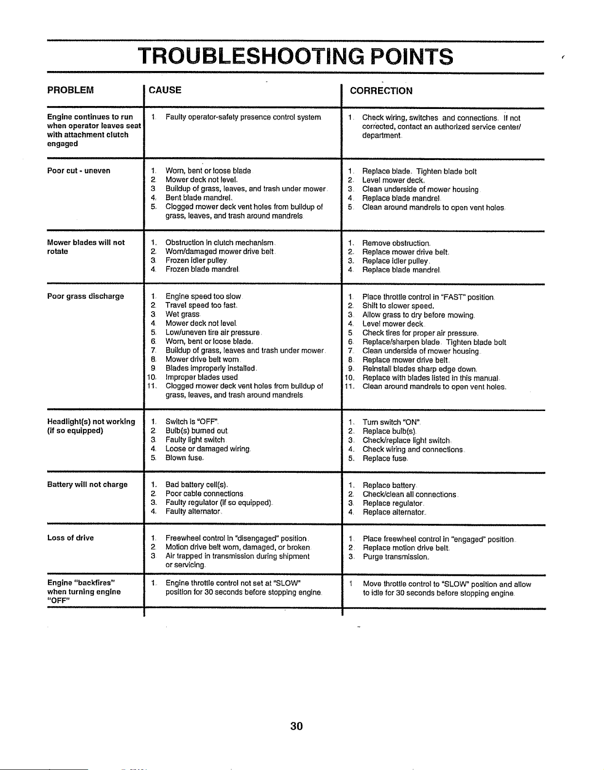
LESHOOTING POINTS
PROBLEM
Engine continues to run
when operator leaves seat
with attachment clutch
engaged
Poor cut - uneven
CAUSE
1 Faulty operator-safety presence control system
1. Worn, bent orloose blade
2. Mower deck not level
3
4,
5.
Buitdup of grass, leaves, and trash under mower.
Bent blade mandrel.
Clogged mower deck vent holes from buildup of
CORRECTION
1. Check wiring, switches and connections, if not
corrected, contact an authorized service canted
department.
1. Replace blade° Tighten blade belt
2 Levet mower deck.
3. Clean underside of mower housing
4. Replace blade mandrel.
5. Clean around mandrels to open vent holes.
Mower blades will not
rotate
Poor grass discharge
Headlight{s)not worklng
(tf so equipped)
L
Battery will not charge
Loss of drive
,,,,, ,, , ,,,
Engine "backfires"
when turning engine
"OFF"
grass_ leaves, and trash around mandrels
1., Obstruction In clutch mechanism.
2. Worn/damaged mower drive belt.
3. Frozen Fdler pulley.
4. Frozen blade mandrel.
1. Engine speed too stow
2. Travel speed too fast.
3 Wet grass
4 Mower deck not level.
5. Lowtuneven tire air pressure.
6. Worn, bent or loose blade°
7. Buildup of grass, leaves and trash under mower.
8. Mowerddvebeltwom.
9 Blades improperly Installed.
t0. improper blades used
t 1., Clogged mower deck vent holes from buildup of
grass, leaves, and trash around mandrels
1. Switch is "OFF",
2. Bulb(s) burned out.
3. Faulty light switch
4. Loose or damaged wiring,
5, Blown fuse.
1,, Bad battery cell(s).
2, Poor cable connections
3.. Faulty regulator (If so equipped).
4. Faulty alternator.
1. Freewheel control in"disengaged" position.
2. Motion drive belt worn, damaged, or broken.
3 Air trapped in transmission during shipment
or servicing.
1,
Engine throttle control not set at "SLOW"
position for 30 seconds before stopping engine,
I. Remove obstruction.
2. Replace mower drive belt.,
3, Replace idler puIley.
4. Replace blade mandrel.
I. Place throttle control in "FAST" position.
2. ShiftIo slower speed,
3 AIIow grass to dry before mowing,
4, Level mower deck
5 Check tires for proper air pressure.
6. Replace/sharpen blade. Tighten blade bolt
7. Clean underside of mower housing
8 Replace mower drive belt.
9- Reinsta!l blades sharp edge down,
10., Replace with blades listed in this manuaI.
11., Clean around mandrals to open vent holes..
1. Turn switch "ON".
2, Replace bulb(s),
3, Check/replace light switch.
4., Check wiring and connections
5., Replace fuse.
1. Replace battery
2, Check/dean eli connections.
3. Replace regulalor.
4. Replace alternator..
1 Place freewheel control in "engaged" position
2. Replace motion drive belt.
3 Purge transmission..
Move throttle control to "SLOW" position and allow
to idle for 30 seconds before slopping engine.
3O
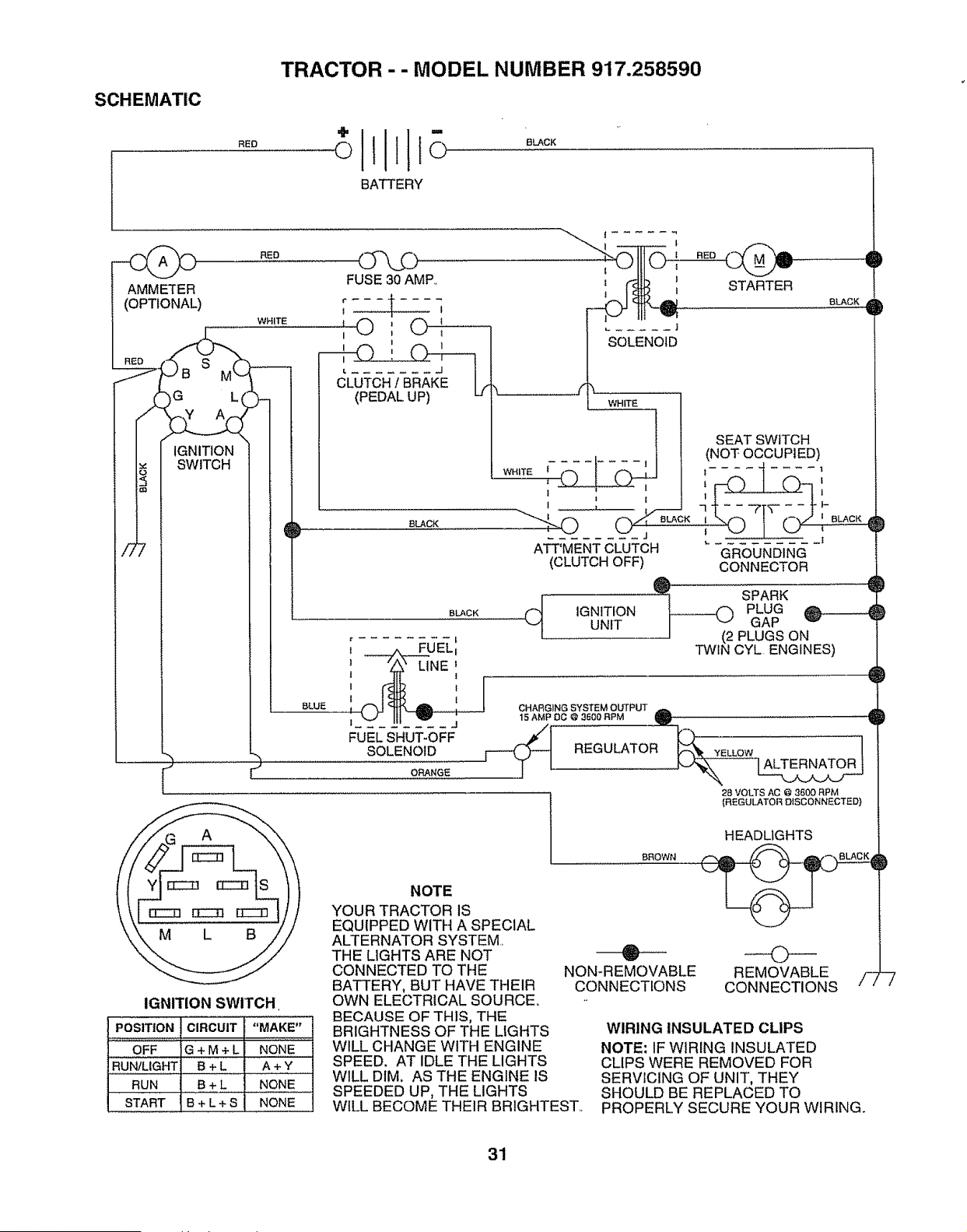
SCHEMATIC
REO
TRACTOR - - MODEL NUMBER 917.258590
O
BATTERY
BLACK
AMMETER
(OPTIONAL)
IGNITION
SWITCH
RED
WHITE
FUSE 30 AMP,.
,© , ©,
8LACK
BLUE
BLACK
ORANGE
| .....
SOLENOID
WHITE
STARTER
OLAGK D
[ _UEL:
' !
1 "_' LINE
!
!
1 A
FUELSHUT-OFF
SOLENOID
WHITE _I
1
z I
I
"'%0 0"_"_°'
ATT'MENTCLUTCH
(CLUTCH OFF)
Cl IGNITIONuNIT
SEAT SWITCH
(NOT OCCUPIED)
7 f - - 7T_-- - - i" _-
','--o f
GROUNDING
CONNECTOR
O SPARK
__)(2 PLuG
GAP
PLUGS ON
TWIN CYL ENGINES)
CHARGING SYSTEM OUTPUT
15 AMP OC @ 3600 RPM m ......................
REGULATOR _t "YELLOW
28 VOLTS AC @ 3600 RPM
[REGULATOR DISCONNECTED)
IGNITION SWITCH
PosITIoN CIRCUIT "MAKE"
OFF G + M + L NONE
RUN/LIGHT B + L A + Y
RUN B + L NONE
START B + L + S NONE
NOTE
YOUR TRACTOR IS
EQUIPPED WITH A SPECIAL
ALTERNATOR SYSTEM,
THE LIGHTS ARE NOT
CONNECTED TO THE
BATTERY, BUT HAVE THEIR
OWN ELECTRICAL SOURCE,
BECAUSE OF THIS, THE
BRIGHTNESS OF THE LIGHTS
WILL CHANGE WITH ENGINE
SPEED. AT IDLE THE LIGHTS
WILL DIM, AS THE ENGINE IS
SPEEDED UP, THE LIGHTS
BROWN
HEADLIGHTS
D
0
NON-REMOVABLE REMOVABLE /7 -7
CONNECTIONS CONNECTIONS
WIRING INSULATED CLIPS
NOTE: IF WIRING INSULATED
CLIPS WERE REMOVED FOR
SERVICING OF UNIT, THEY
SHOULD BE REPLACED TO
WILL BECOME THEIR BRIGHTEST, PROPERLY SECURE YOUR WIRING.
31
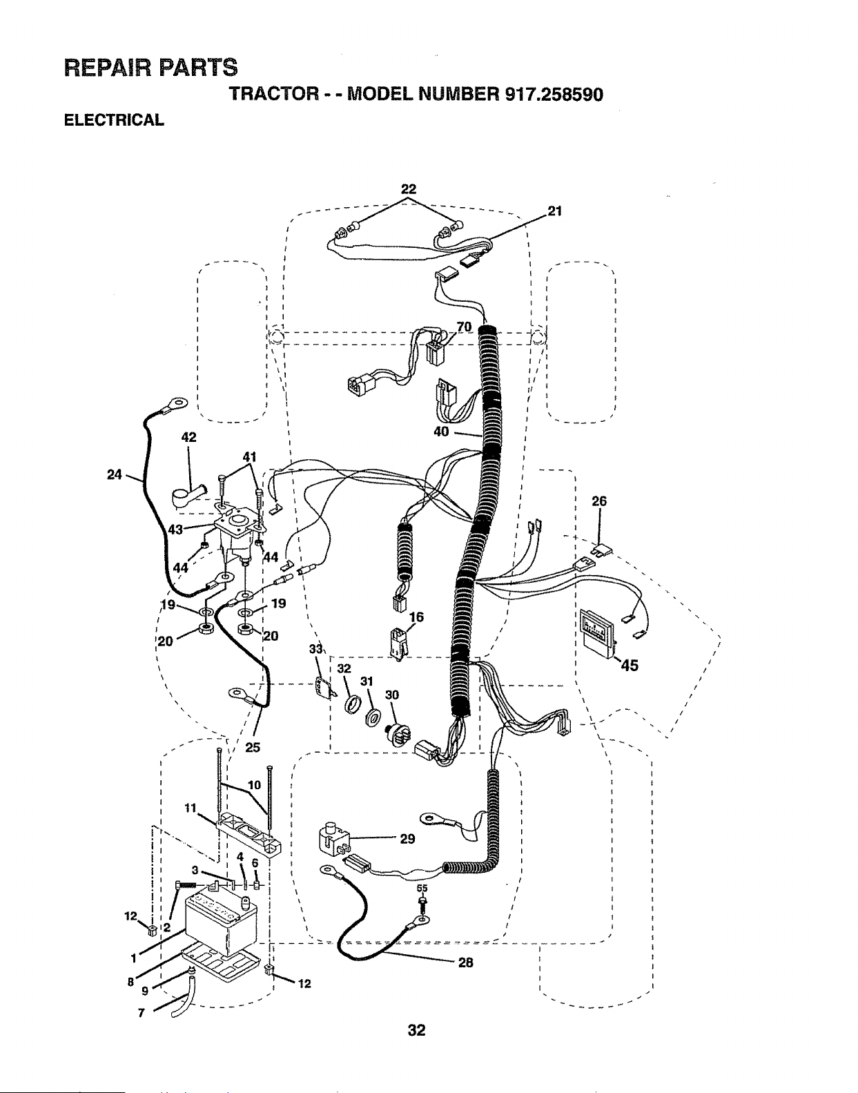
REPAIR PARTS
TRACTOR - - MODEL NUMBER 917.258590
ELECTRICAL
24
42
22
/
!
12o
\
\\
\
\
!
I
32
REPAIR PARTS
TRACTOR -- MODEL NUMBER 917.258590
ELECTRICAL
KEY PART
NO. NO. DESCRIPTION
1 144926
2 74760412
3 STD551025
4 STD551125
6 STD541025
7 7697J
8 7603J
9 109596X
10 145211
11 150109
12 145769
16 153664
19 STD551t25
20 73350400
21 136850
22 4152J
24 146136
25 146148
26 108824X
28 145491
29 121305X
30 140301
31 124211X
32 141226
33 109310X
40 156149
41 71110408
42 131563
43 145673
44 73640400
45 122822X
55 17490508
70 140426
Battery 12 Volt 30 Amp
Bolt, Hex Head 1/4-20 uric x 3/4
Washer
Washer
Nut
Tube, Plastic, 46"
Tray, Battery
Clamp, Hose
Bolt BTR FRT 1-4-20 x 7.5
Holddown Battery
Nut, Push Nylon 1/4 Bat. FrL
Switch Interlock Push-In
Washer, Lock
Nut, Hex, Jam 1/4-20 UNC
Harness, Light Socket
(Includes 4152J)
Bulb, Light
Cable, Battery, 6 Gauge, Red, 24"
Cable, Battery, 6 Gauge, Red, W/
16 Wir 22"
Fuse, 30 Amp
Cable, Ground, 6 Gauge, Black, 21"
Switch, Plunger
Switch, Ignition
Nut, Ignition
Cover, Key Switch
Key, Ignition
Harness, Ignition
Bolt, Hex Head, Fin.. 1/4-20 x 1/2
Cover', Terminal, Red
Solenoid
Nut Keps Btk Hex 1/4-20 UNC
Ammeter Rectangular 15 Amp
Screw, Thdro! 5/16-18 x 1/2
Harness Engine Koh Cmd-L 15AR
NOTE: All component dimensions given in U,,S, inches
1 inch = 25,,4 mm
33
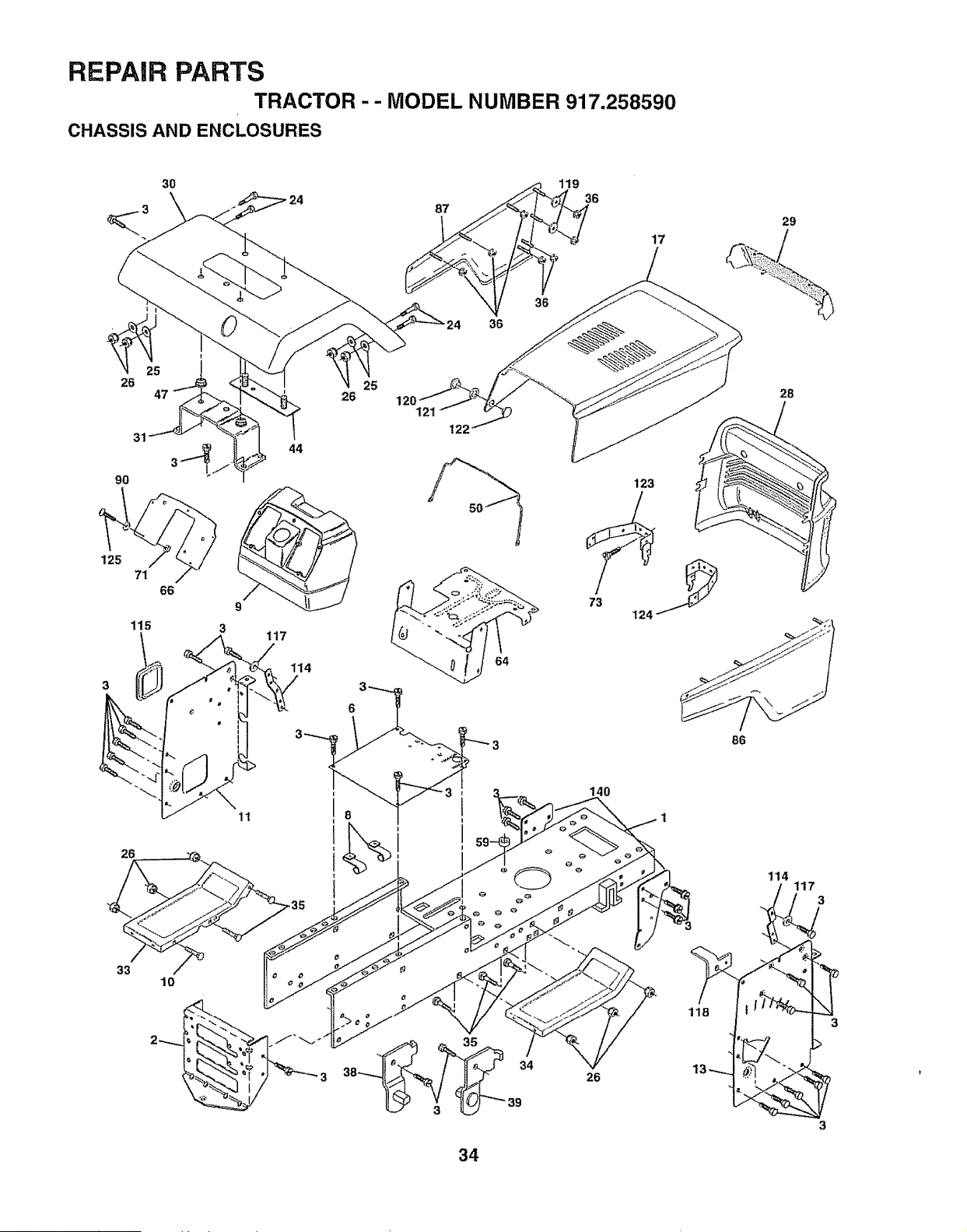
REPAIR PARTS
TRACTOR -- MODEL NUMBER 917.258590
CHASSIS AND ENCLOSURES
3O
\
26
31
9O
26
26
44
87
36
25
121
119
36
36
17
33
10
26
29
28
86
118
114
3
3
34
REPAIR PARTS
TRACTOR -- MODEL NUMBER 917.258590
CHASSIS AND ENCLOSURES
KEY PART
NO. NO. DESCRIPTION
1 155051 Chassis
2 140356 Drawbar
3 17490612 Screw, Thdrol. 3/8-16 x 3/4 Type TT
6 155923 Saddle
8 126471X Clip, Fuel Line
9 145203 Dash, Plastic
10 72140608 Bolt, Carriage 3/8-16 x 1
11 145218 Panel, Dash, LH
13 145217 Panel, Dash, RH
17 136673X558 Hood Assembly
24 STD523710 Bolt
25 19131312 Washer 13/32 x t3/16 x 12 Gauge
26 STD541437 Nut
28 136373X428 Grill
29 136374 Lens, Bar, Clear
30 140002X558 Fender
31 137113 Bracket Assembly, Fender
33 t45244X558 Footrest, LH
34 145243X558 Footrest, RH
35 STD533707 Bolt
36 108067X Nut, Pal
38 139886 Bracket Assembly, Pivot, LH
39 139887 Bracket Assembly, Pivot, RH
44 140675 Fender Strap
47 105531X Nut, Push, Nylon
50 137304 Rod, Support Hood
59 110436X Bushing, Snap, Split
64 150272 Dash, Lower
66 156276X012 Plate, Dash
71 73640400 Nut
73 17580408 Screw Tap Tite 1/4-20 x 1/2
86 I36670X558 PanelAssembly, RH
87 136671X558 PanelAssembly, LH
90 STD551025 Washer 17/64
114 145349 Bracket, Support, Dash
115 121794X Cover', Access
117 144283 Washer Serrated Disk 13/32 x t
118 145595 Bracket, Clutch Mech SRS YT 95
119 19092016 Washer 9/32 x 1-1/4 x 16 Ga_
120 137271 Rivet, Ratchet, Female
121 137269 Washer, Nylon
122 137270 Rivet, Rachet, Male
t23 157105 Bracket Assembly, Pivot, Hood LH
!24 157107 Bracket Assembly, Pivot, Hood RH
125 74180412 Screw, Machine 1/4-20 x 3/4
140 158418 Bracket SuspensionFront
- - 5479J Plug, Btn Blk 359 Diao
NOTE: All component dimensions given in U.S. inches
1 inch = 25.4 mm
35
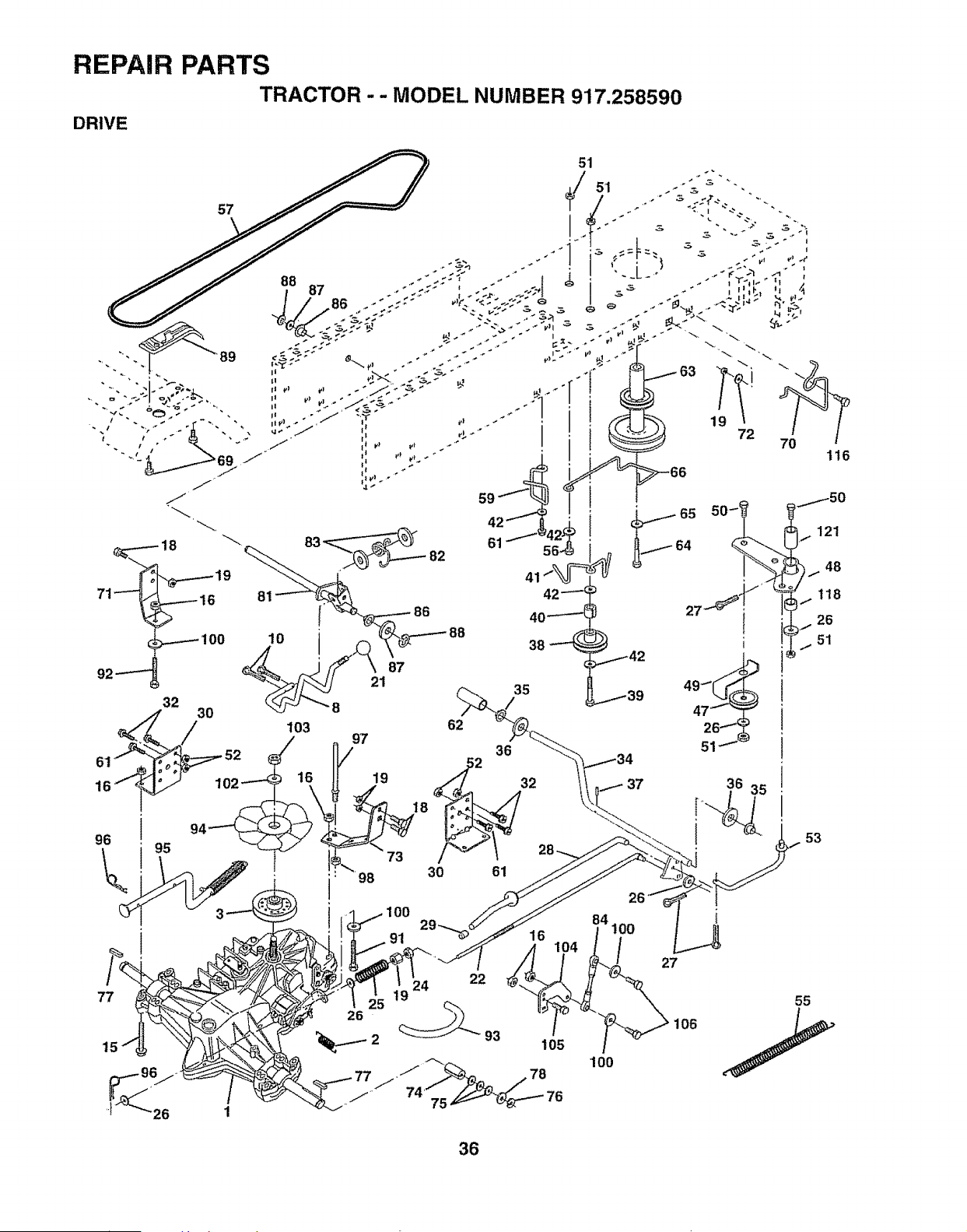
REPAIP, pARTS
T_ACTOR
. . MODEL NUMBER 9!7.258590
51
J
59
62
03 97 36
__ 30 61
/ 91
+tOO
06
36
53
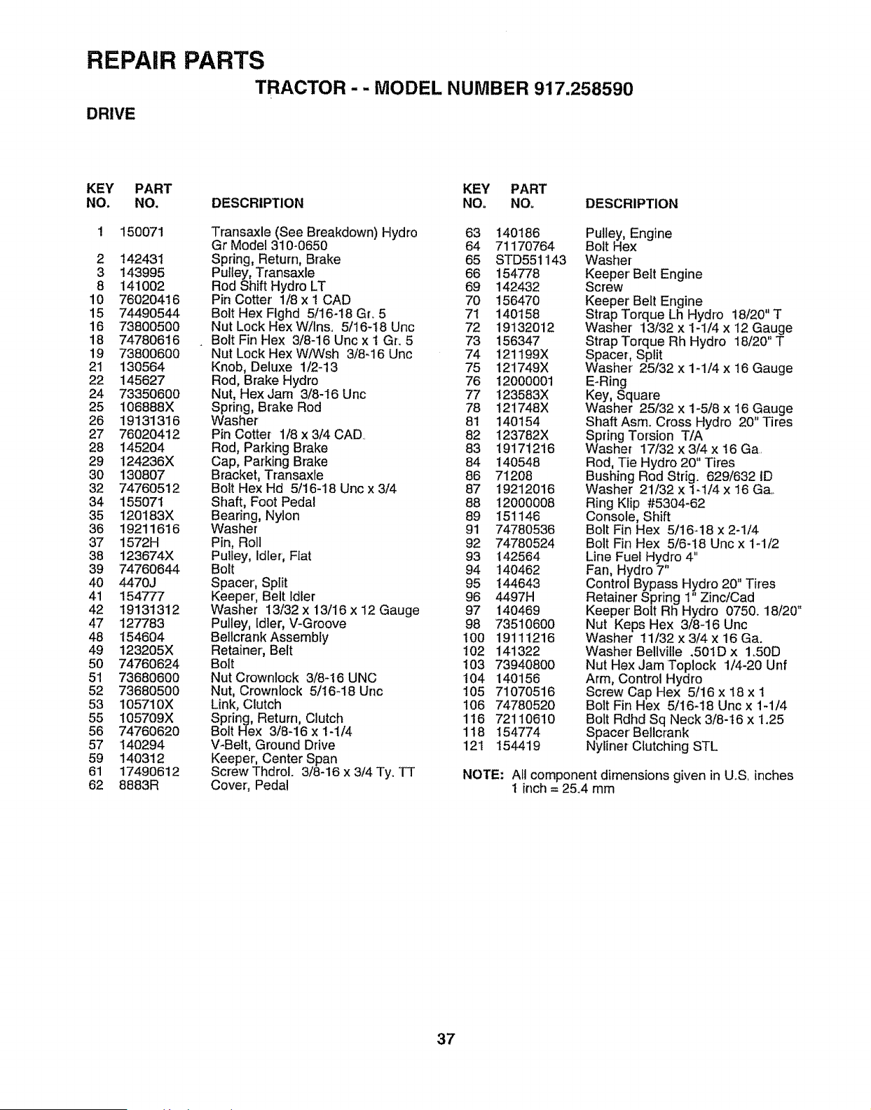
REPAIR PARTS
TRACTOR -- MODEL NUMBER 917.258590
DRIVE
KEY PART KEY PART
NO. NO. DESCRIPTION NO. NOo DESCRIPTION
1 150071 Transaxle (See Breakdown) Hydro 63 140t86
Gr Model 310-0650 64 71170764
2 142431 Spring, Return, Brake 65 STD551143
3 143995 Pulley, Transaxle 66 154778
8 141002 Rod Shift Hydro LT 69 142432
10 76020416 Pin Cotter' 1/8 x I CAD 70 156470
15 74490544 Bolt Hex Flghd 5/16-18 Gro 5 7t 140158
16 73800500 Nut Lock HexW/Inso 5/16-18 Uric 72 19132012
18 74780616 . Bolt Fin Hex 3/8-16Uncxt Gr. 5 73 156347
19 73800600 Nut Lock Hex W/Wsh 3/8-16 Unc 74 121199X
21 130564 Knob, Deluxe 1/2-13 75 121749X
22 145627 Rod, Brake Hydro 76 t2000001
24 73350600 Nut, Hex Jam 3/8-16 Unc 77 123583X
25 106888X Spring, Brake Rod 78 !21748X
26 19131316 Washer 81 140154
27 76020412 Pin Cotter 1/8 x 3/4 CAD, 82 123782X
28 145204 Rod, Parking Brake 83 19171216
29 124236X Cap, Parking Brake 84 140548
30 130807 Bracket, Transaxle 86 71208
32 74760512 Bolt Hex Hd 5/16-18 Unc x3/4 87 19212016
34 15507i Shaft, Foot Pedal 88 12000008
35 120183X Bearing, Nylon 89 151146
36 19211616 Washer 91 74780536
37 1572H Pin, Roll 92 74780524
38 123674X Pu!ley, Idler, Flat 93 142564
39 74760644 Bolt 94 t40462
40 4470J Spacer', Split 95 !44643
41 154777 Keeper, Belt Idler 96 4497H
42 19131312 Washer I3/32x 13/16 x 12 Gauge 97 140469
47 127783 Pulley, idler, V-Groove 98 73510600
48 154604 BellcrankAssembly t00 191!1216
49 123205X Retainer', Belt 102 141322
50 74760624 Bolt t03 73940800
51 73680600 Nut Crownlock 3/8-16 UNC 104 140156
52 73680500 Nut, Crownlock 5/16-18 Unc 105 71070516
53 105710X Link, Clutch 106 74780520
55 105709X Spring, Return, Clutch 116 72110610
56 74760620 Bolt Hex 3/8-16 x 1-1/4 1t8 154774
57 140294 V_Belt, Ground Drive 121 154419
59 140312 Keeper, Center Span
61 17490612 Screw Thdrol. 3/8-16 x 3/4 Ty. TT
62 8883R Cover, Pedal
Pulley, Engine
Bolt Hex
Washer
Keeper' Belt Engine
Screw
Keeper Belt Engine
Strap Torque Lh Hydro 18/20" T
Washer 13/32 x 1-1/4 x 12 Gauge
Strap Torque Rh Hydro 18/20" T
Spacer, Split
Washer 25/32 x 1-1/4 x 16 Gauge
E-Ring
Key, Square
Washer 25/32 x I-5/8 x 16 Gauge
Shaft Asm, Cross Hydro 20" Tires
Spring Torsion T/A
Washer 17/32 x 3/4 x 16 Ga
Rod, Tie Hydro 20" Tires
Bushing Rod Stdg. 629/632 ID
Washer 21/32 x 1-1/4 x 16 Ga,,
Ring Klip #5304-62
Console, Shift
Bolt Fin Hex 5/16-18 x 2-1/4
Bolt Fin Hex 5/6-18 Unc x 1-1/2
Line Fuel Hydro 4"
Fan, Hydro 7"
Control Bypass Hydro 20" Tires
Retainer Spring 1" Zinc/Cad
Keeper' Bolt Rh Hydro 0750. 18/20"
Nut Keps Hex 3/8-16 Unc
Washer 11/32 x 3/4 x 16 Ga.
Washer Bellville .501D x 1.50D
Nut Hex Jam Toplock 1/4-20 Unf
Arm, Control Hydro
Screw Cap Hex 5/16 x 18 x 1
Bolt Fin Hex 5/16-18 Uric x 1-1/4
Bolt Rdhd Sq Neck 3/8-t6 x 1.25
Spacer Bellcrank
Nyliner Clutching STL
NOTE: Afl component dimensions given in U,S inches
I inch = 25.4 mm
37
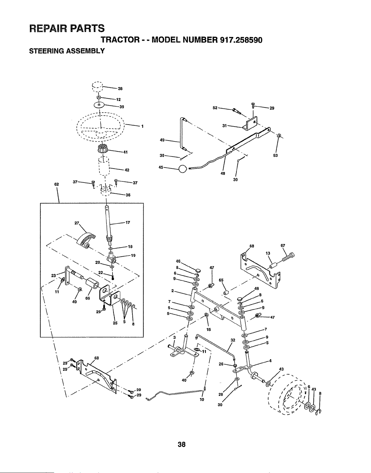
REPAIR PARTS
TRACTOR -- MODEL NUMBER 917.258590
STEERING ASSEMBLY
62
39
4B
68
28
10
30
67
43
38
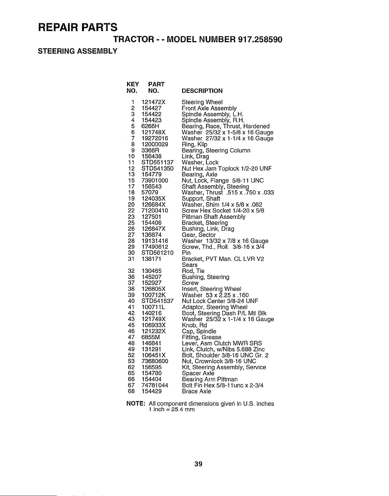
REPAIR PARTS
TRACTOR -- MODEL NUMBER 917.258590
STEERING ASSEMBLY
KEY PART
NO. NO. DESCRIPTION
1 121472X
2 154427
3 154422
4 154423
5 6266H
6 121748X
7 19272016
8 12000029
9 3366R
10 156438
11 STD551137
12 STD541350
13 154779
15 73901000
17 156543
18 57079
19 124035X
20 126684X
22 71200410
23 127501
25 154406
26 126847X
27 136874
28 19131416
29 17490612
30 STD561210
31 138171
32 130465
36 145207
37 152927
38 126805X
39 1007t2K
4O STD541537
41 100711L
42 140216
43 121749X
45 106933X
46 121232X
47 6855M
48 146841
49 131291
52 106451X
53 73680600
62 156595
65 154780
66 154404
67 74781044
68 154429
Steering Wheel
Front Axle Assembly
Spindle Assembly, LH.
Spindle Assembly, RH.
Bearing, Race, Thrust, Hardened
Washer' 25/32 x 1-5/8 x 16 Gauge
Washer 27/32 x 1-1/4 x 16 Gauge
Ring, Ktip
Bearing, Steering Column
Link, Drag
Washer, Lock
Nut Hex Jam Toplock 1/2-20 UNF
Bearing, Axle
Nut, Lock, Flange 5/8-11 UNC
Shaft Assembly, Steering
Washer, Thrust _515 x °750 x _033
Support, Shaft
Washer, Shin] 1/4 x 5/8 x °062
Screw Hex Socket 1/4-20 x 5/8
Pittman Shaft Assembly
Bracket, Steering
Bushing, Link, Drag
Gear, Sector
Washer 13/32 x 7/8 x 16 Gauge
Screw, Thd., Roll, 3/8-16 x 3/4
Pin
Bracket, PVT Man. CL LVR V2
Sears
Rod, Tie
Bushing, Steering
Screw
Insert, Steering Wheel
Washer 53 x 2°25 x .160
Nut Lock Center 3/8-24 UNF
Adaptor, Steering Wheel
Boot, Steering Dash P/L Mtl Bfk
Washer 25/32 x 1-1/4 x 16 Gauge
Knob, Rd
Cap, Spindle
Fitting, Grease
Lever, Asm Clutch MWR SRS
Link, Clutch, w/Nibs 5.688 Zinc
Bolt, Shoulder 3/8-16 UNC Gr. 2
Nut, Crownlock 3/8-16 UNC
Kit, Steering Assembly, Service
Spacer AxJe
Bearing Arm Pittman
Bolt Fin Hex 518-11unc x 2-3/4
Brace Axle
NOTE: All component dimensions giver_in UoS inches
1 inch = 254 mm
39
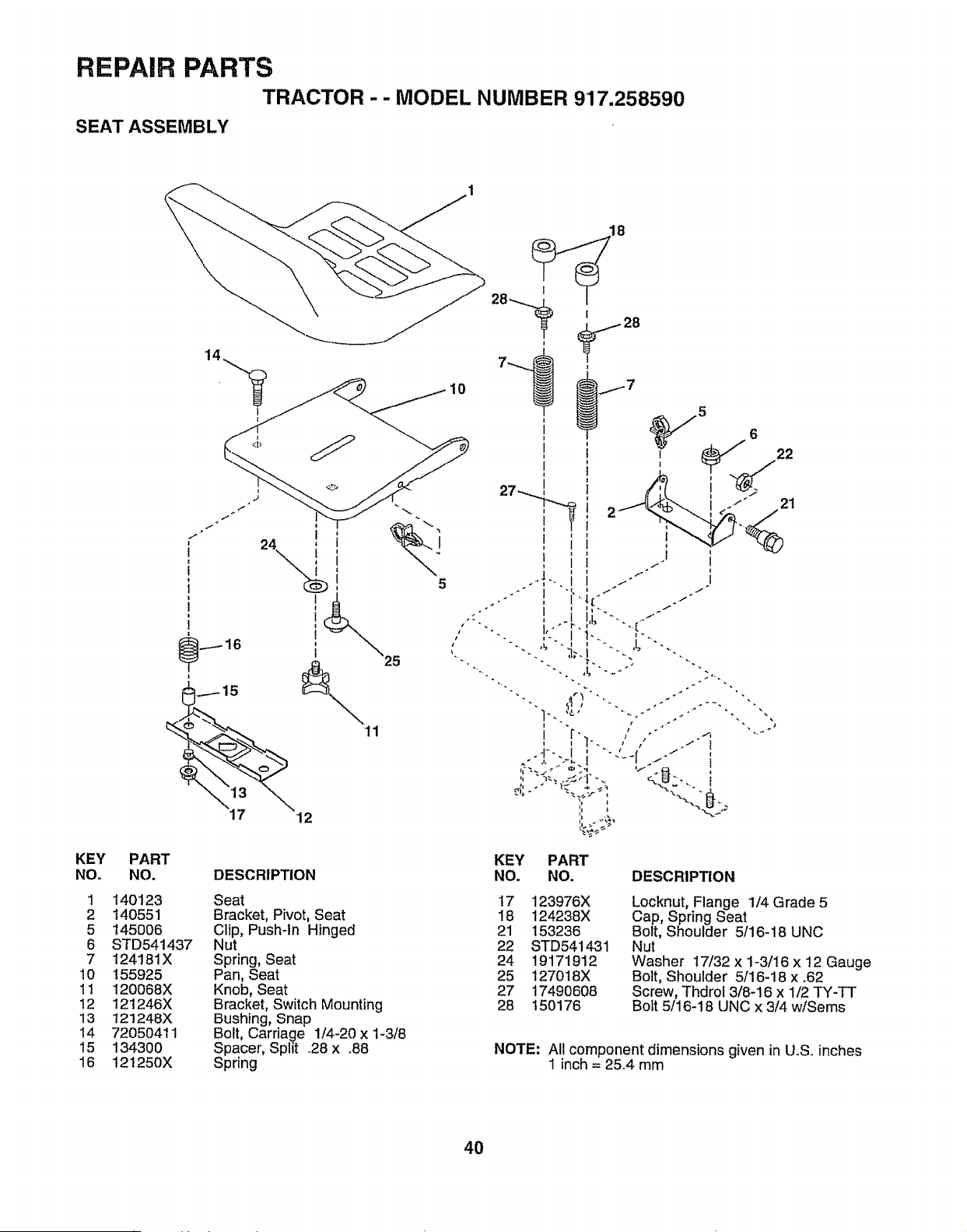
REPAIR PARTS
TRACTOR - - MODEL NUMBER 917.258590
SEAT ASSEMBLY
KEY PART
NOo NO,
1 140123
2 140551
5 145006
6 STD541437
7 124181X
10 155925
1t 120068X
12 121246X
13 121248X
14 72050411
15 134300
16 121250X
18
28-.-....__ 28
12
5
21
KEY PART
DESCRIPTION NO, NO, DESCRIPTION
Seat
Bracket, Pivot, Seat
Clip, Pushqn Hinged
Nut
Spring, Seat
Pan, Seat
Knob, Seat
Bracket, Switch Mounting
Bushing, Snap
Bolt, Carriage 1/4-20 x 1-3/8
Spacer, Split .28 x .88
Spring
17 123976X
18 124238X
21 153236
22 STD541431
24 19171912
25 127018X
27 17490608
28 150176
Locknut, Flange 1/4 Grade 5
Cap, Spring Seat
Bolt, Shoulder 5/16-18 UNC
Nut
Washer 17/32 x 1-3/16 x 12 Gauge
Bolt, Shoulder 5/16-18 x .62
Screw, Thdrol 3/8-16 x 1/2 TY-TT
Bolt 5/16-I 8 UNC x 3/4 wiSems
NOTE: All component dimensions given in U.S. inches
1 inch = 25.4 mm
4O
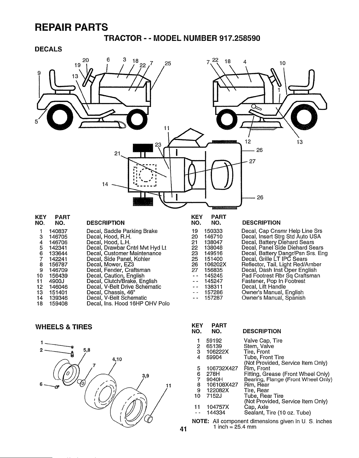
REPAIR PARTS
TRACTOR - - MODEL NUMBER 917.258590
DECALS
9
19
20 6 3 18 7 25 7.
/
11
18 4
10
21
12 13
26
14
26
KEY PART
NO. NO.
1 140837 Decaf
3 146705 Decal
4 146706 Decal
5 142341 Decal
6 133644 Decal
7 142241 Decal
8 156787 Decal
9 146709 Decal
10 156439 Decal
tl 4900J Decal
12 146046 Decal
t3 151401 Decal
14 139346 Decal
18 159408 Decal
DESCRIPTION
KEY
NO.
Saddle Parking Brake 19
Hood, R.H° 20
Hood, L.H. 21
Drawbar Cntrl Mvt Hyd Lt 22
Customer Maintenance 23
Side Panel, Kohler 25
Mower, EZ3 26
Fender, Craftsman 27
Caution, English - -
Clutch/Brake, English - -
V-Belt Drive Schematic - -
Chassis, 46" - -
V-Belt Schematic - -
Ins. Hood 16HP OHV Polo
PART
NO,
150333
146710
138047
138048
149516
15140O
106202X
156835
145245
145247
138311
157286
157287
DESCRIPTION
Decal, Cap Cnsmr Help Line Srs
Decal, Insert Strg Std Auto USA
Decal, Battery Diehard Sears
Decal, Panel Side Diehard Sears
Decal, Battery Dangr/Psn Srs_ Eng
Decal, Grille LT IPC Sears
Reflector, Tail, Light Red/Amber
Decal, Dash lnst Oper English
Pad Footrest Rbr Sq Craftsman
Fastener, Pop In Footrest
Decal, Lift Handle
Owner's Manual, English
Owner's Manual, Spanish
4_10
7
11
41
KEY PART
NO. NO. DESCRIPTION
1 59192 Valve Cap, Tire
2 65139 Stem, Valve
3 106222X Tire, Front
4 59904 Tube, Front Tire
(Not Provided, Service item Only)
5 106732X427 Rim, Front
6 278H Fitting, Grease (Front Wheel Only)
7 9040H Bearing, Flange (Front Wheel Only)
8 106108X427 Rim, Rear
9 122082X Tire, Rear
10 7152J Tube, Rear Tire
(Not Provided, Service Item Only)
11 104757X Cap, Axle
- - 144334 Sealant, Tire (10 oz_Tube)
NOTE: All component dimensions given in U. S. inches
1 inch = 25.4 mm
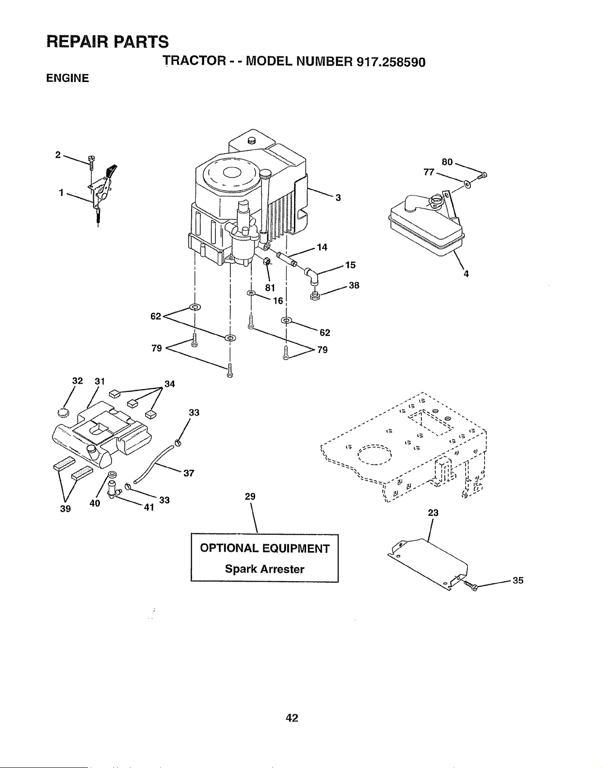
REPAIR
ENGINE
PARTS
TRACTOR - - MODEL NUMBER 917.258590
32 31
©
40
39
I
34
29
\
OPTIONAL EQUIPMENT
Spark Arrester
8O
77 ._.."_
4
23
135
42
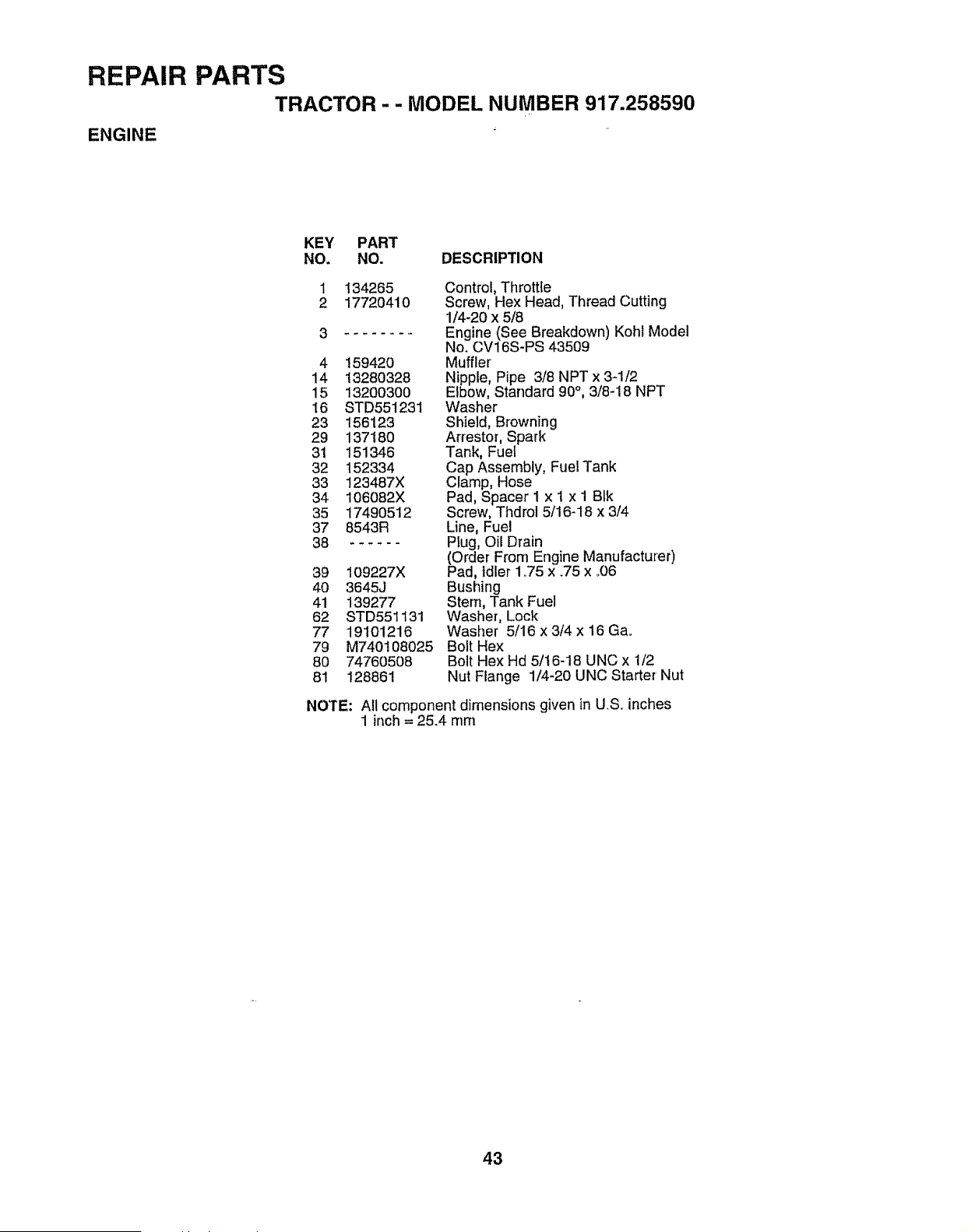
REPAIR PARTS
TRACTOR - - MODEL NUMBER 917.258590
ENGINE
KEY PART
NO, NO. DESCRIPTION
1 134265 Contro!, Throttle
2 17720410 Screw, Hex Head, Thread Cutting
1/4-20 x 5/8
3 ........ Engine (See Breakdown) Kohl Model
No. CV16S-PS 43509
4 !59420 Muffler
14 13280328 Nipple, Pipe 3/8 NPT x 3_1/2
15 13200300 Elbow, Standard 90°, 3/8-18 NPT
16 STD551231 Washer
23 156123 Shield, Browning
29 137180 Arrestor, Spark
31 151346 Tank, Fuel
32 152334 Cap Assembly, FueITank
33 123487X Clamp, Hose
34 106082X Pad, Spacer I x ! x I BIk
35 17490512 Screw, Thdrol 5/16-18 x 3/4
37 8543R Line, Fuel
38 ...... Ptug, Oil Drain
(Order From Engine Manufacturer)
39 109227X Pad, Idler 1o75 x .75 x °06
40 3645J Bushing
41 139277 Stem, Tank Fuel
62 STD551131 Washer, Lock
77 19101216 Washer 5/16 x 3/4 x 16 Ga.
79 M740108025 BoltHex
80 74760508 Bolt Hex Hd 5/16-18 UNC x 1/2
81 128861 Nut Flange 1/4-20 UNC Starter Nut
NOTE: All component dimensions given in U.S. inches
1 inch= 25.4 mm
43
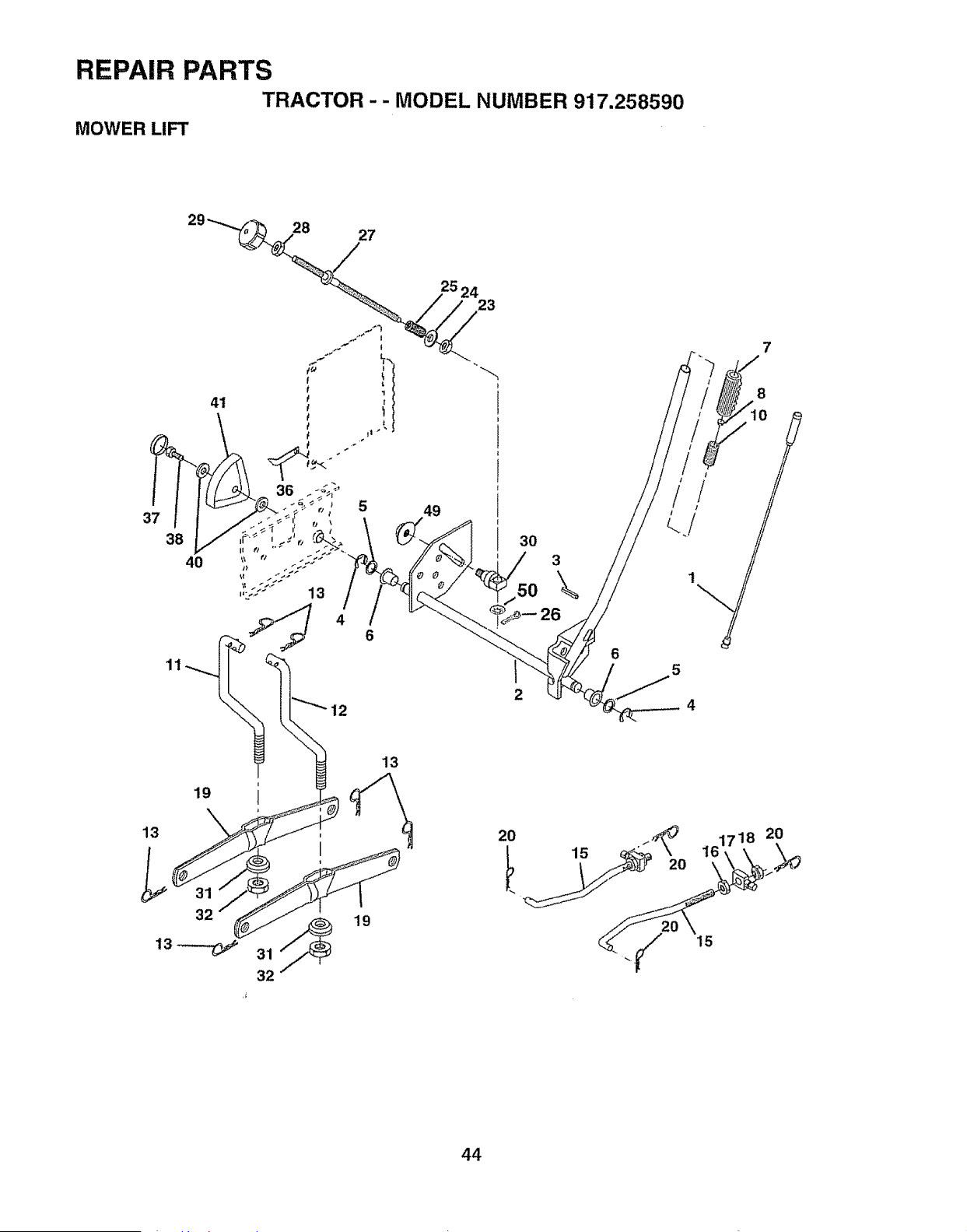
REPAIR PARTS
TRACTOR -- MODEL NUMBER 917.258590
MOWER LIFT
37
38
40
41
!
4
6
11
2524
23
49
30
50
3
\
26
6
5
7
8
10
19
13
32
i
32
19
13
20
i_ 16171820
20 __
44
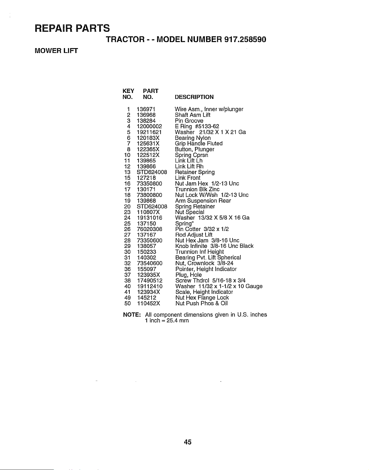
REPAIR PARTS
TRACTOR - - MODEL NUMBER 917.258590
MOWER LIFT
KEY PART
NO. NO. DESCRIPTION
1 136971 Wire Asm., Inner w/plunger
2 136968 Shaft Asm Lift
3 t38284 . Pin Groove
4 12000002 E Ring #5133-62
5 19211621 Washer 2t/32 X 1 X 21 Ga
6 120183X Bearing Nylon
7 125631X Grip Handle Ftuted
8 122365X Button, Plunger
10 122512X Spring Cprsn
11 i39865 Link Lift Lh
12 139866 Link LiftRh
13 STD624008 Retainer Spring
15 127218 Link Front
16 73350800 Nut Jam Hex 1/2-13 Unc
17 130171 Trunnion BlkZinc
18 73800800 Nut Lock W/Wsh 1/2-13 Unc
19 t39868 Arm Suspension Rear
20 STD624008 Spring Retainer'
23 t10807X Nut Special
24 19131016 Washer' 13/32 X 5/8 X 16 Ga
25 137150 Spring"
26 76020308 Pin Cotter' 3/32 x 1/2
27 137167 Rod Adjust Lift
28 73350600 Nut Hex Jam 3/8-16 Unc
29 138057 Knob Infinite 3/8-16 Uric Black
30 150233 Trunnion Inf Height
31 140302 Bearing Pvto Lift Spherical
32 73540600 Nut, Crownlock 3/8-24
36 155097 Pointer, Height indicator
37 123935X Plug, Hole
38 17490512 ScrewThdrol 5/16_t8 x3/4
40 19112410 Washer 11/32 x 1-1/2 x 10 Gauge
41 123934X Scale, Height Indicator
49 145212 Nut Hex Flange Lock
50 110452X Nut Push Phos & Oil
NOTE; All component dimensions given in U.S_ inches
1 inch = 25,4 rnm
45
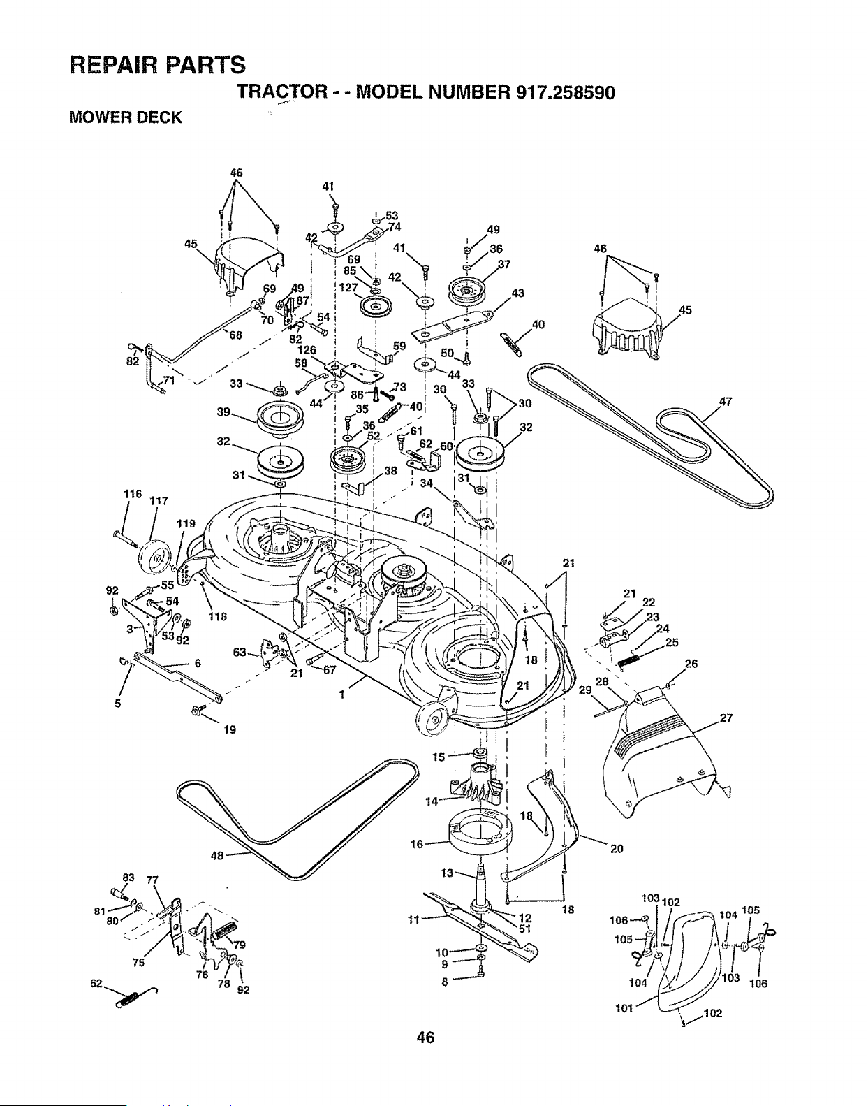
REPAIR PARTS
TRACTOR - - MODEL NUMBER 917.258590
MOWER DECK _
46
41
116
117
15
21
21
23
24
25
28 _ _.
29
26
27
81
83 77
/
76
78
92
9
8
46
103102
1_ lO6
101 ._7102
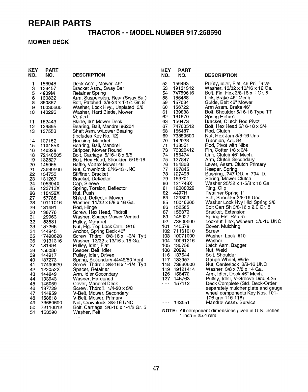
REPAIR PARTS
TRACTOR - - MODEL NUMBER 917.258590
MOWER DECK
KEY PART KEY PART
NO. NO. DESCRIPTION NO. NO, DESCRIPTION
! 156948
3 138457
5 4939M
6 130832
8 850857
9 10030600
10 140296
11 152443
12 129895
13 137553
14 137152
15 110485X
16 140329
18 72140505
19 132827
20 145055
21 73680500
22 134753
23 131267
24 105304X
25 123713X
26 110452X
27 157788
28 19111O16
29 131491
30 138776
3i 129963
32 153531
33 137266
34 144945
35 17490628
36 19131316
37 131494
38 156086
39 144917
40 137273
41 17490620
42 122052X
43 144949
44 133943
45 145059
46 137729
47 144959
48 158818
49 73680600
50 72110612
51 153390
Deck Asm,, Mower 46" 52
Bracket Asm_, Sway Bar 53
Retainer Spring 54
Arm, Suspension, Rear' (Sway Bar) 58
Bolt, Patched 3/8-24 x 1-1/4 Gr. 8 59
Washer, Lock Hvy., Unplated 3/8 60
Washer, Hard Blade, Mower 61
Vented 62
Blade, 46" Mower Deck 63
Bearing, Ball, Mandrel #6204 67
Shaft Asm. w/Lower Bearing 68
(includes Key No. 12) 69
Housing, Mandrel 70
Bearing, Ball, Mandrel 71
Stripper, Mower Round 73
Bolt, Carriage 5/16-18 x 5/8 74
Bolt, Hex Head, Shoulder 5/16-18 75
Baffle, Vortex Mower 46" 76
Nut, Crownlock 5/t6-18 UNC 77
Stiffiner, Bracket 78
Bracket, Deflector 79
Cap, Sleeve 80
Spring, Torsion, Deflector' 81
Nut, Push 82
Shield, Deflector Mower 83
Washer- 11/32 x 5/8 x 16 Ga. 85
Rod, Hinge 86
Screw, Hex Head, Thdroll 87
Washer, Spacer Mower Vented 89
Pulley, Mandrei 92
Nut, FIgoTop Lock Cntr. 9/16 101
Anchor, Spring Deck 46" 102
Screw, Thdroll 3/8-16 x 1-3/4 Tytt 103
Washer 13/32 x 13/16 x 16 Ga_ t04
Pulley, Idler-, Flat 105
Keeper, Belt, Idler 106
Pulley, Idler', Driven 116
Spring, Secondary 44/46/50 Vent 117
Screw, Thdrotl 3/8-16 x 1-t/4 Tytt 1t8
Spacer, Retainer 119
Arm, Idler Secondary 126
Washer, Hardened 127
Cover, Mandrel Deck - - -
Screw, Thdroll. 1/4-20 x 5/8
V-Belt, Mower, Secondary
V-Belt, Mower, Primary
Nut, Crownlock 3/8_16 UNC - - -
Bolt, Carriage 3/8-16 x 1-1/2 Gr..5
Washer, Felt
156493
19131312
74780616
156488
157034
156722
139888
131870
156473
74760512
156487
73350600
142028
133551
76020412
156474
127847
154808
127845
127498
153701
121748X
12000029
4497H
129803
10O4O6O0
158565
158373
146927
73800600
145579
71161010
1007100O
19061216
130758
2029J
137644
133957
7393060O
19121414
156472
146763
157112
143651
Pulley, Idler, Flat, 46 Pri. Drive
Washer, 13/32 x t3/16 x 12 Ga..
Bolt, Fin_Hex 3/8-16 x I Gro5
Link, Brake 46" Mech
Guide, Belt 46" Mower
Arm Assm. Brake 46"
Bolt, Shoulder' 5/16-18 Type TT
Spring Return
Bracket, Clutch Rod Pivot
Bolt, Hex Head 5/16-18 x 3/4
Rod, Clutch
Nut, Hex Jam 3/8-16 Unc
Trunnion, Adj._94
Rod, Pivot with Nibs
Pin, Cotter 1/8 x 3/4
Link, Clutch 46" Mech_
Arm, Clutch Secondary
Lever, Assm° Clutch Primary
Keeper, Spring
Bushing, .747 OD.. x ..794 ID.
Spring, Mower Clutch
Washer 25/32 x 1-5/8 x 16 Ga_
Ring, Clip
Retainer Spring 1"
Bolt, Shoulder' 3/8-16 Uric
Washer Lock Hvy Hlcl Spring 3/8
Bolt Cart Sh 3/8-16 x 2_0Gr,.5
Bracket, Extension
Spring Ext.. Return
Locknut, Hex, w!lnsert 3/8-16 UNC
Cover, Mulching
Screw
Washer, Lock #10
Washer
Latch Asm_ Bagger
Nut, Weld
Bolt, Shoulder
Gauge Wheel, Wide
Nut, Centerlock 3/8-16 UNC
Washer 3/8 x 7/8 x 14 Ga_
Arm, idler, Deck 46" Mech..
Pulley, Idler, V-Groove Dim. 4,.25
Deck Complete (Std.. Deck-Order
separately mulcher plate and gauge
wheel components Key Nos_.101-
106 and 116-118)
Mandrel Assmo Service
NOTE: All component dimensions given in U.S inches
1 inch = 25..4 rnm
47
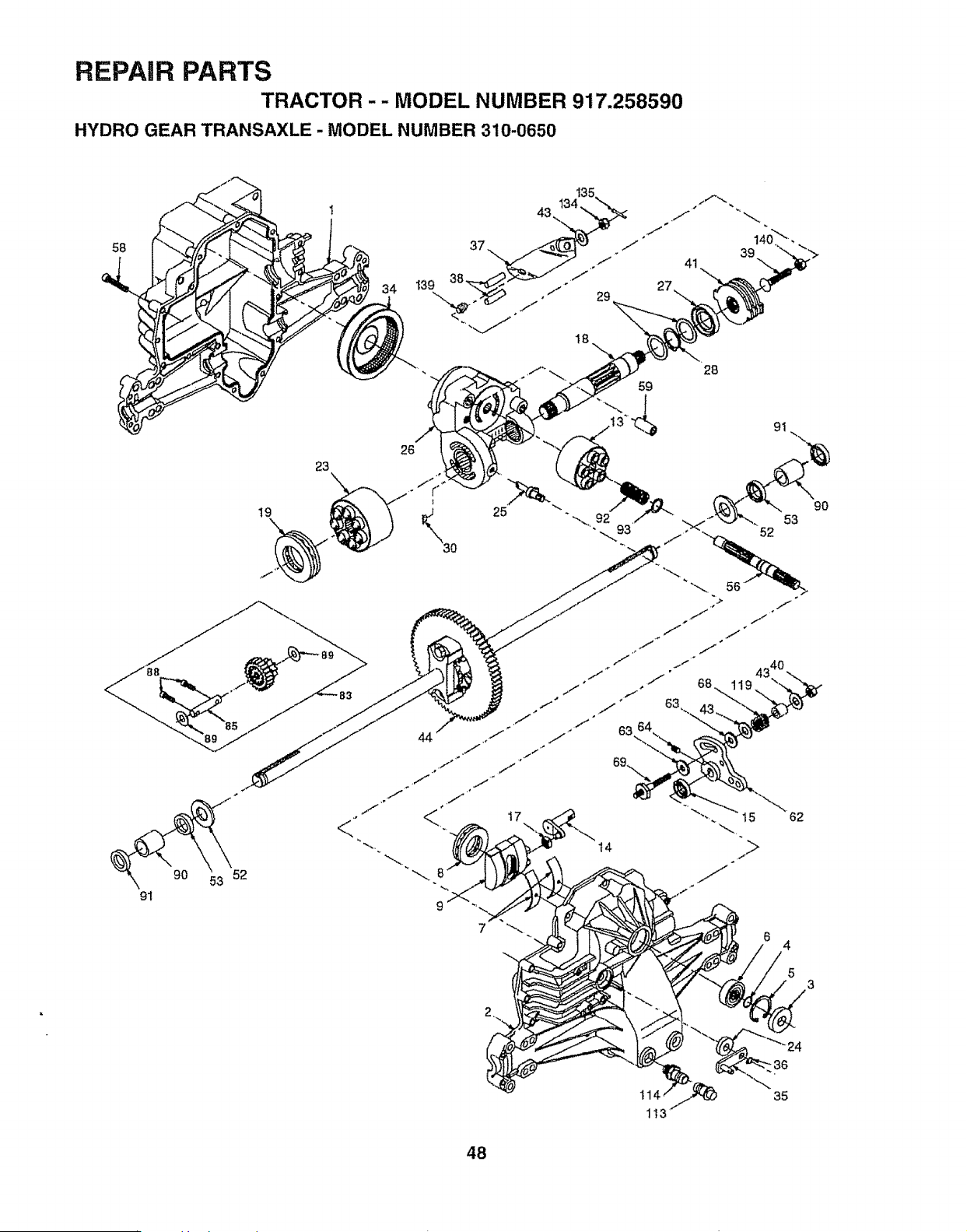
REPAIR PARTS
TRACTOR - - MODEL NUMBER 917.258590
HYDRO GEAR TRANSAXLE - MODEL NUMBER 310-0650
58
90 33 52
91
23
\
19
34
39140_ "
26
18
28
59
t4
4
5
t14
1t3
"36
35
48
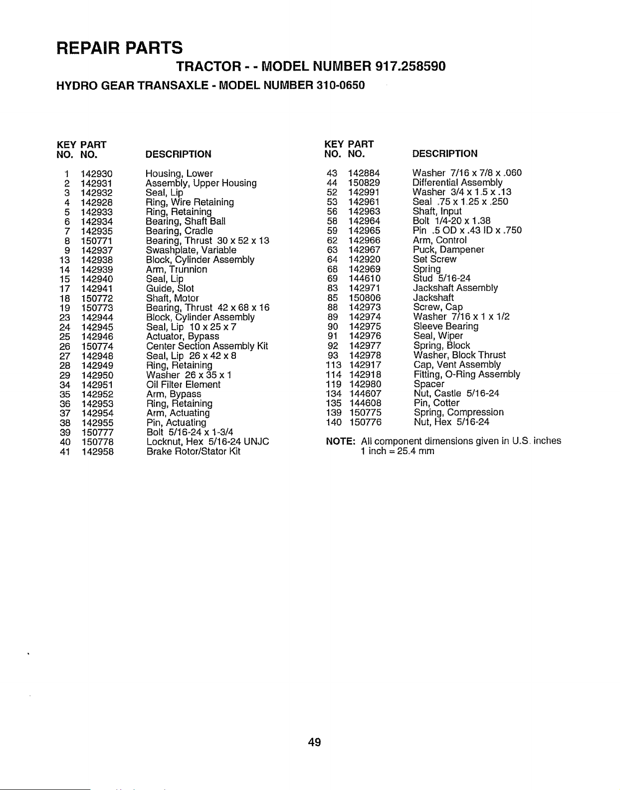
REPAIR PARTS
TRACTOR -- MODEL NUMBER 917.258590
HYDRO GEAR TRANSAXLE - MODEL NUMBER 310-0650
KEY PART KEY PART
NO. NO. DESCRIPTION NO, NO. DESCRIPTION
1 142930 Housing, Lower 43 142884 Washer' 7/16 x 7/8 x .060
2 142931 Assembly, Upper Housing 44 150829 Differential Assembly
3 142932 Seal, Lip 52 142991 Washer 3/4 x t5 x.13
4 142928 Ring, Wire Retaining 53 142961 Seal °75 x 1.25 x.250
5 142933 Ring, Retaining 56 142963 Shaft, Input
6 142934 Bearing, Shaft Ball 58 142964 Bolt 1/4-20 x 1.38
7 142935 Bearing, Cradle 59 142965 Pin o50D x,43 1Dx .750
8 150771 Bearing, Thrust 30 x 52 x 13 62 142966 Arm, Control
9 142937 Swashptate, Variable 63 142967 Puck, Dampener'
13 142938 Block, Cylinder Assembly 64 142920 Set Screw
14 142939 Arm, Trunnion 68 142969 Spring
15 142940 Seal, Lip 69 144610 Stud 5/16-24
17 142941 Guide, Slot 83 142971 Jackshaft Assembly
18 150772 Shaft, Motor 85 150806 Jackshaft
19 150773 Bearing, Thrust 42 x 68 x 16 88 142973 Screw, Cap
23 142944 Block, Cylinder Assembly 89 142974 Washer 7/16 x I x 1/2
24 142945 Seal, Lip I0 x25x7 90 142975 Sleeve Bearing
25 142946 Actuator, Bypass 91 142976 Seal, Wiper
26 150774 Center Section Assembly Kit 92 142977 Spring, Block
27 142948 Seal, Lip 26 x 42 x 8 93 142978 Washer, Block Thrust
28 142949 Ring, Retaining 113 142917 Cap, VentAssembfy
29 142950 Washer 26 x 35 x 1 114 142918 Fitting, O-Ring Assembly
34 142951 Oil Filter Element 119 142980 Spacer
35 142952 Arm, Bypass 134 144607 Nut, Castle 5/16-24
36 142953 Ring, Retaining 135 144608 Pin, Cotter
37 142954 Arm, Actuating 139 150775 Spring, Compression
38 142955 Pin, Actuating 140 150776 Nut, Hex 5/16-24
39 150777 Bolt 5/16-24 x 1-3/4
40 150778 Locknut, Hex 5/16-24 UNJC NOTE: All component dimensions given in UoS.inches
4t 142958 Brake Rotor!Stator Kit 1 inch = 25°4 mm
49
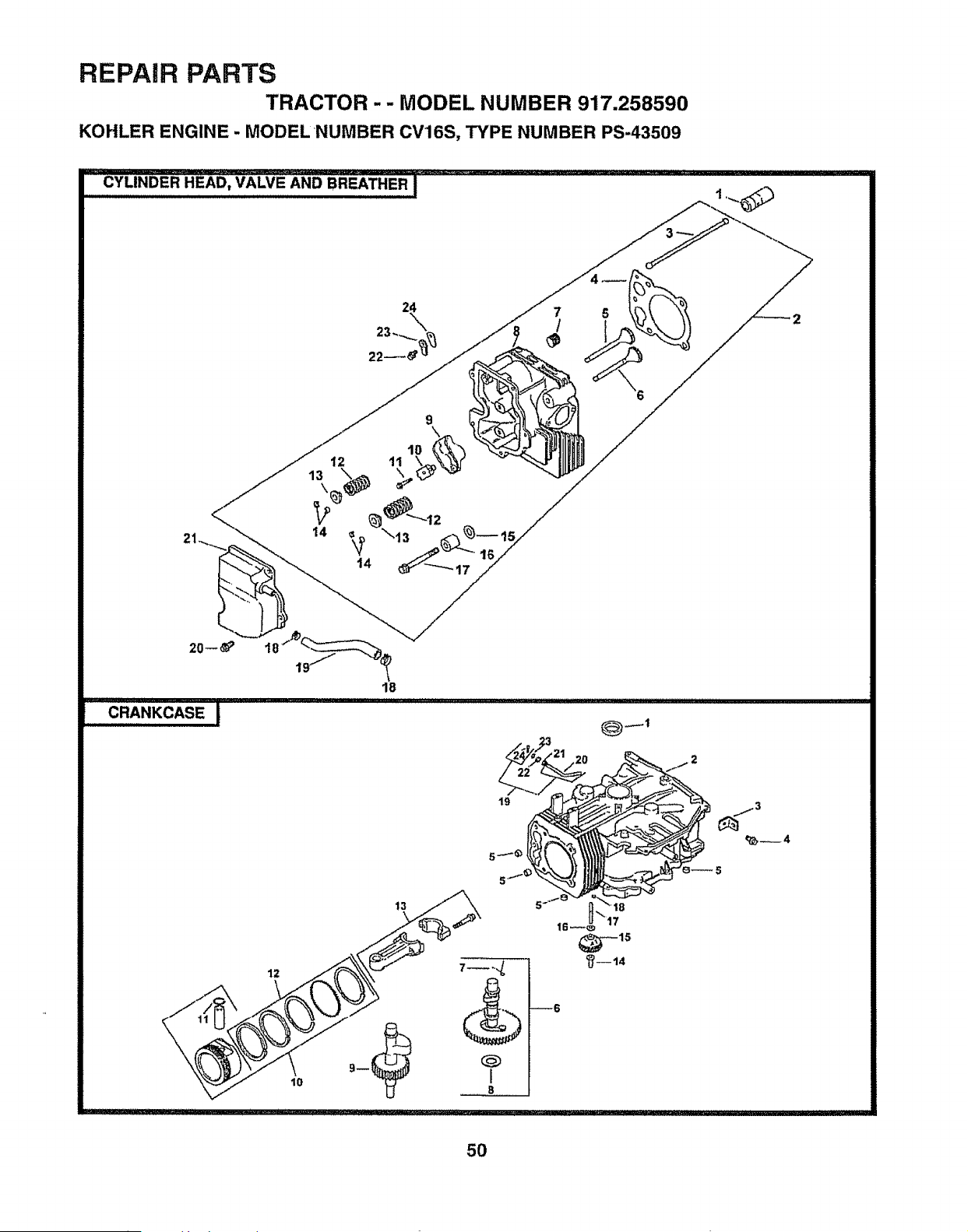
REPAIR PARTS
TRACTOR - - MODEL NUMBER 917.258590
KOHLER ENGINE - MODELNUMBER CV16S, TYPE NUMBER PS-43509
......CYLINDE-RHEA0,VA"LvEANOBREATHERI
22
9
14 _ \13
14
CRANKCASE
18
19
_,_4
5O
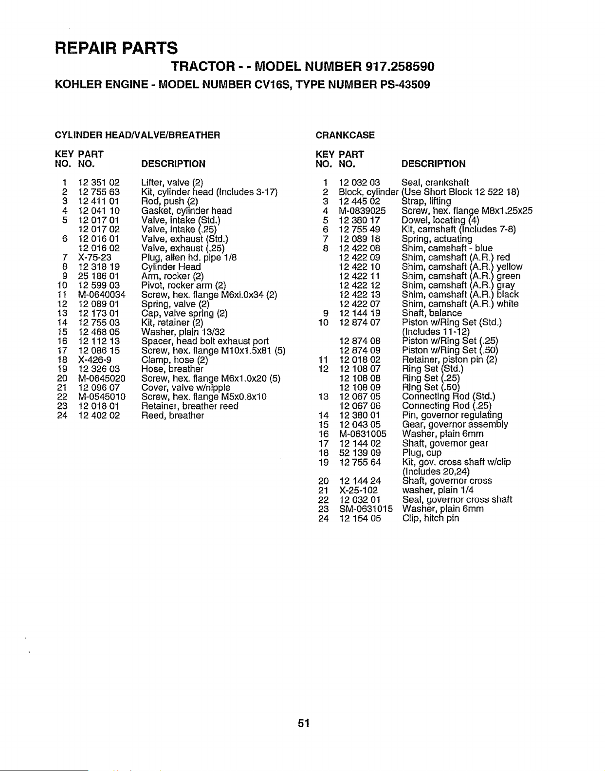
REPAIR PARTS
TRACTOR - - MODEL NUMBER 917.258590
KOHLER ENGINE - MODEL NUMBER CV16S, TYPE NUMBER PS-43509
CYLINDER HEAD/VALVE/BREATHER
CRANKCASE
KEY PART KEY PART
NO. NO. DESCRIPTION NO. NO. DESCRIPTION
1
2
3
4
5
12 351 02
12 755 63
12 411 01
12 041 10
12 017 01
t2 017 02
t2 016 01
t2 016 02
X-75-23
12 318 19
25 186 01
12 599 03
M-0640034
12 089 01
12 173 01
t2 755 03
12 468 05
1211213
12 086 15
X-426-9
12 326 O3
M-0645020
12 096 07
M-0545010
1201801
12 402 02
Lifter, valve (2) 1 12 032 03
Kit, cylinder head (includes 3-17) 2 Block, cylinder
Rod, push (2) 3 12445 02
Gasket, cylinder' head 4 M-0839025
Valve, intake (Std.) 5 12 380 17
Valve, intake (°25) 6 12 755 49
Valve, exhaust (Std..) 7 12 089 18
Valve, exhaust (,25) 8 12 422 08
Plug, allen hd. pipe 1/8 12 422 09
Cylinder Head 12 422 10
Arm, rocker (2) 12 422 11
Pivot, rocker arm (2) 12 422 12
Screw, hexoflange M6xL0x34 (2) 12 422 !3
Spring, valve (2) 12 422 07
Cap, valve spring (2) 9 t2 144 19
Kit, retainer (2) 10 12 874 07
Washer, plain 13/32
Spacer, head bolt exhaust port
Screw, hex. flange M10x1.5x81 (5)
Clamp, hose (2)
Hose, breather
Screw, hex. flange M6x1.0>'.20(5)
Cover, valve w/nipple
Screw, hex. flange M5x0_8xl0
Retainer, breather reed
Reed, breather
7
8
9
10
11
12
13
14
15
16
17
18
19
20
21
22
23
24
12 874 08
12 874 09
11 12 018 O2
12 12 108 07
12 108 08
12 108 09
13 12 O67 05
12 067 06
t4 12 380 01
15 12 043 05
16 M-0631005
17 12 144 02
18 52 139 O9
19 !2 755 64
2O t2 144 24
21 X-25-102
22 12 032 01
23 SM-063t015
24 12 154 05
Sea!, crankshaft
(Use Short Block 12 522 !8)
Strap, lifting
Screw, hex. flange MSx1.25x25
Dowel, locating (4)
Kit, camshaft (Includes 7-8)
Spring, actuating
Shim, camshaft - b_ue
Shim, camshaft (A.R.) red
Shim, camshaft (AoR.) yellow
Shim, camshaft (A_R.) green
Shim, camshaft (A°Ro)gray
Shim, camshaft (AoRo)black
Shim, camshaft (AR) white
Shaft, balance
Piston w/Ring Set (Stdo)
(Includes 11-12)
Piston w/Ring Set (.25)
Piston w/Ring Set (°50)
Retainer, piston pin (2)
Ring Set (Std.)
Ring Set (.25)
Ring Set (.50)
Connecting Rod (Stdo)
Connecting Rod (_25)
Pin, governor regulating
Gear, governor assembly
Washer, plain 6mm
Shaft, governor gear
Plug, cup
Kit, gov. cross shaft w/clip
(includes 20,24)
Shaft, governor cross
washer, plain 1/4
Seal, governor cross shaft
Washer, plain 6ram
Clip, hitch pin
51
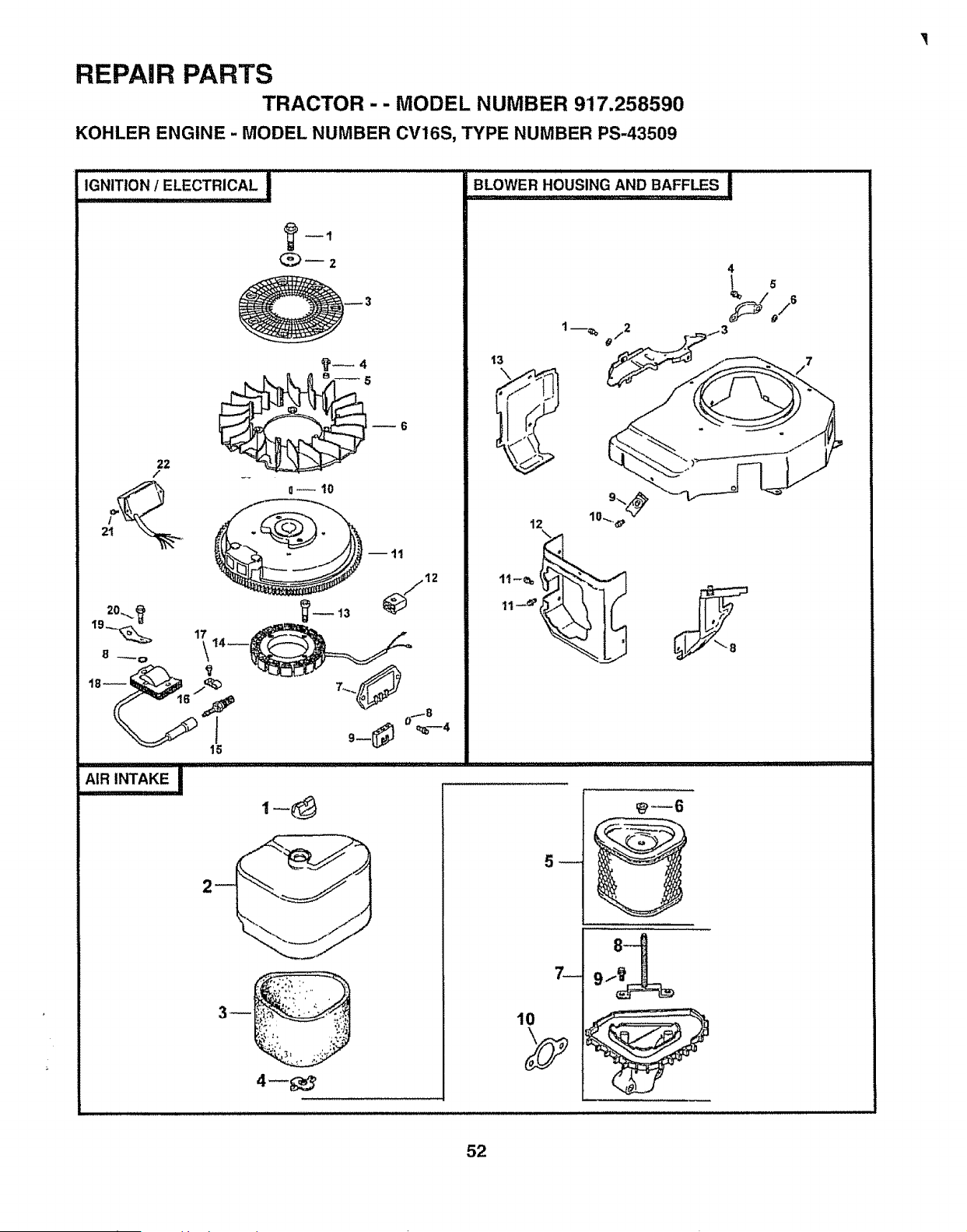
REPAIR PARTS
TRACTOR-- MODEL NUMBER 917,258590
KOHLER ENGINE - MODEL NUMBER CV16S, TYPE NUMBER PS-43509
C_2
22
/
2o...__
19_
_4
o_ 10
2
BLOWER,,HOUS!NG ANDBAFF_S !
13
12
7_
10
! 5
52
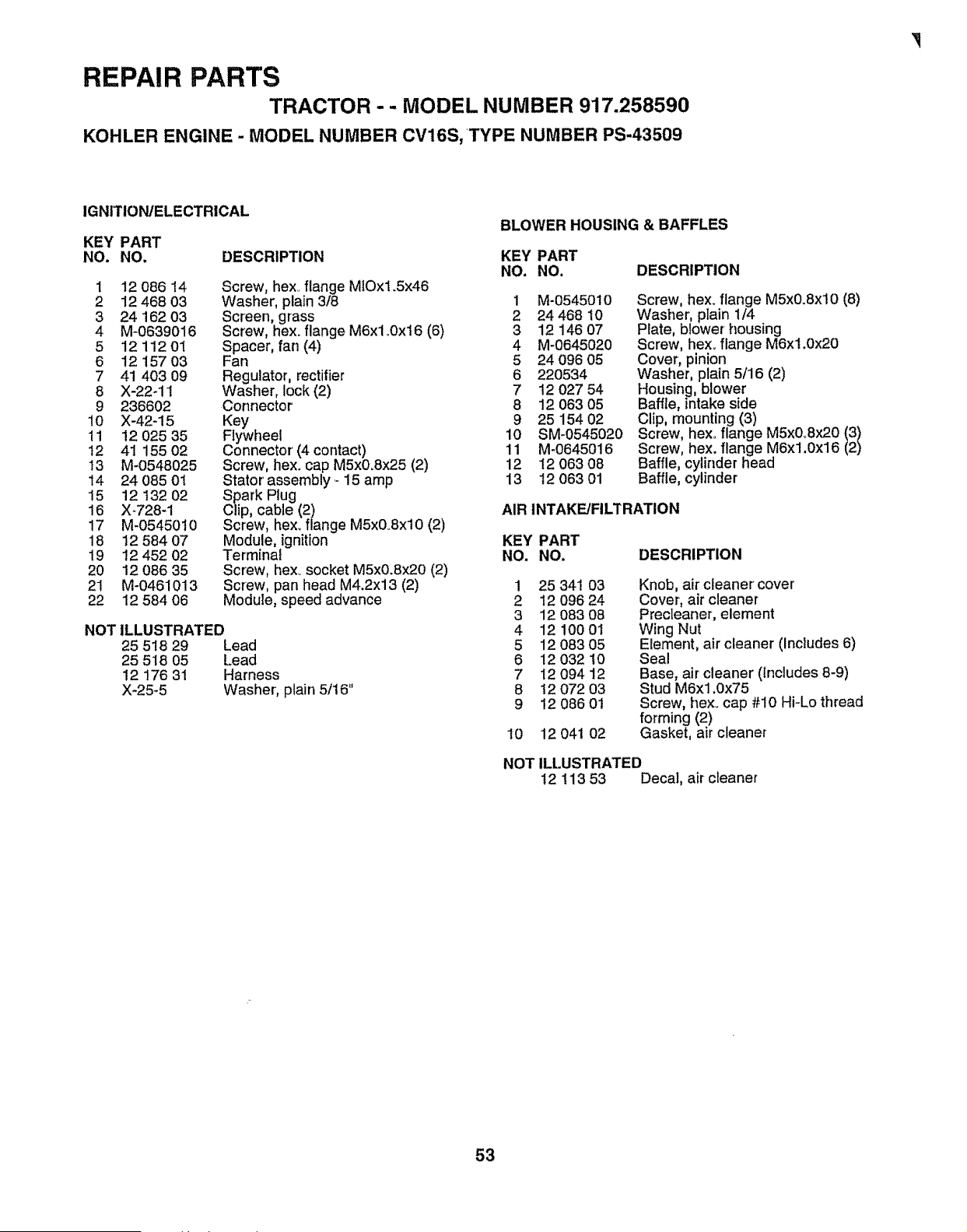
REPAIR PARTS
TRACTOR -- MODEL NUMBER 917.258590
KOHLER ENGINE - MODEL NUMBER CV16S, TYPE NUMBER PS-43509
IGNITION/ELECTRICAL
KEY PART
NO. NO. DESCRIPTION
1 12 086 14
2 12 468 03
3 24 162 03
4 M-0639016
5 12 112 01
6 12 15703
7 41 403 09
8 X-22_11
9 236602
10 X-42-15
11 12 025 35
12 41 155 02
!3 M-0548025
14 24 085 01
15 12 t32 02
16 X_728-1
17 M-05450t0
18 12 584 07
19 12 452 02
20 12 086 35
21 M-0461013
22 12 584 06
Screw, hex.,flange M1Ox1.5x46
Washer, plain 3/8
Screen, grass
Screw, hex. flange M6xl _0x16 (6)
Spacer, fan (4)
Fan
Regulator, rectifier
Washer, lock (2)
Connector
Key
Flywheel
Connector (4 contact)
Screw, hex. cap M5x0.Sx25 (2)
Stator assembly _15 amp
Spark Plug
Clip, cable (2)
Screw, hex. flange M5x0_8xl0 (2)
Module, ignition
Terminal
Screw, hex..socket M5x0.Sx20 (2)
Screw, pan head M4.2x13 (2)
Module, speed advance
NOT ILLUSTRATED
25 518 29 Lead
25 518 05 Lead
12 176 31 Harness
X-25-5 Washer, plain 5/16"
BLOWER HOUSING & BAFFLES
KEY PART
NO. NO. DESCRIPTION
1 M-0545010
2 24 468 10
3 12 146 07
4 M-0645020
5 24 O9605
6 220534
7 12 027 54
8 12 063 O5
9 25 154 02
10 SM-0545020
11 M-0645016
12 12 063 O8
13 12 063 01
Screw, hex. flange M5x0.8xl0 (8)
Washer, plain 1/4
Plate, blower housing
Screw, hex.. flange M6x1.0x20
Cover, pinion
Washer, plain 5/16 (2)
Housing, blower
Baffle, intake side
Clip, mounting (3)
Screw, hexoflange M5xOoSx2013l
Screw, hex. flange M6x1.0x16
Baffle, cylinder head
Baffle, cylinder
AIR INTAKE/FILTRATION
KEY PART
NO. NO.
DESCRIPTION
1
2
3
4
5
6
7
8
9
25 341 O3
12 096 24
12 083 08
12 100 01
12 083 05
12 032 10
12 094 12
t2 072 03
12 086 0t
10 12 041 02
Knob, air cleaner cover
Cover, air cleaner
Precteaner, element
Wing Nut
Element, air cleaner (Includes 6)
Seal
Base, air cleaner (Includes 8-9)
Stud M6x1.0x75
Screw, hex..cap #10 Hi-Lo thread
forming (2)
Gasket, air cleaner
NOTILLUSTRATED
1211353 Decal, aircleaner
53
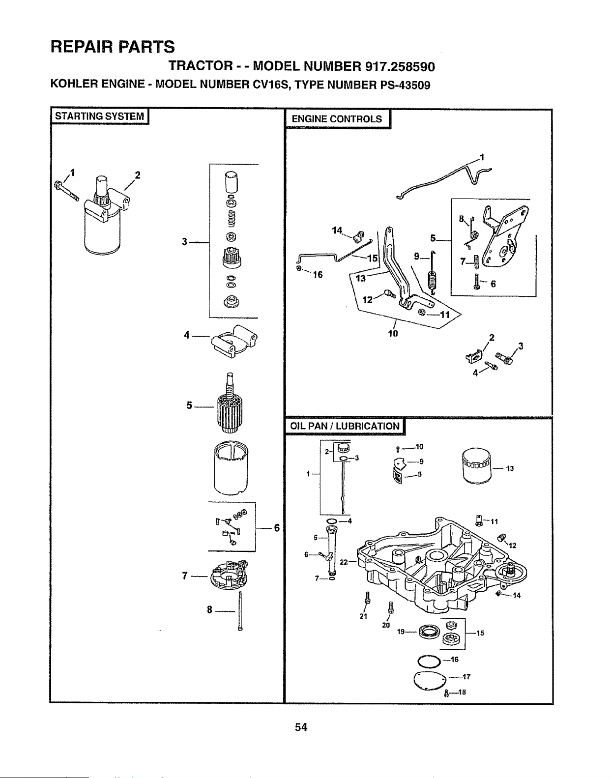
REPAIR PARTS
TRACTOR -- MODEL NUMBER 917.258590
KOHLER ENGINE- MODEL NUMBER CV16S, TYPE NUMBER PS-43509
STARTING SYSTEM I ..................................
2
3_
@
C
@
@
@
6
i ,Ul,!,Jl!,llli,illlllll ii i i i i [
_N_NE CONTROLS i
10 2
....oIL PAN/LUBRICATIO N I ............
21
/
20
_16
_17
54
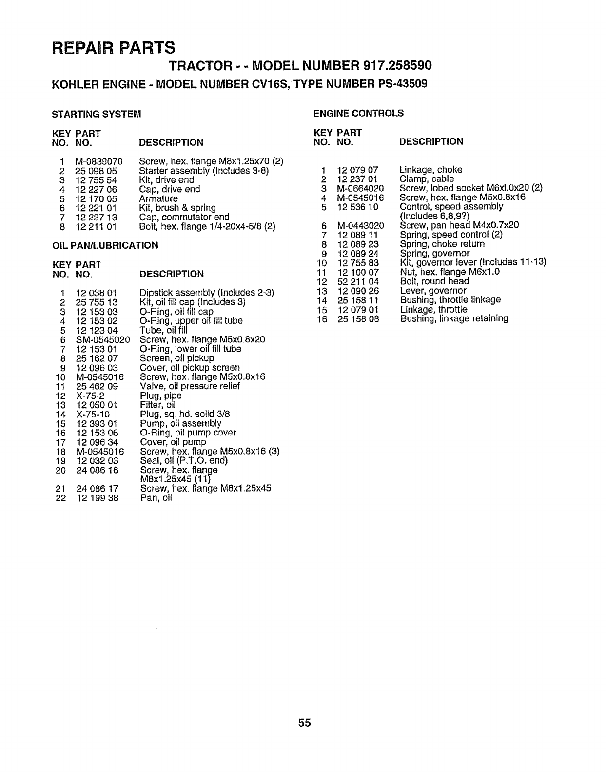
REPAIR PARTS
TRACTOR-- MODEL NUMBER 917,258590
KOHLER ENGINE - MODEL NUMBER CV16S,TYPE NUMBER PS-43509
STARTING SYSTEM ENGINE CONTROLS
KEY PART KEY PART
NO, NO. DESCRIPTION NO. NO. DESCRIPTION
1 M-0839070
2 25 098 05
3 12 755 54
4 12 227 06
5 12 170 05
6 12 22i 01
7 12 227 13
8 12211 01
Screw, hexoflange M8x1.25x70 (2)
Starter assembly (Includes 3_8)
Kit, drive end
Cap, drive end
Armature
Kit, brush & spring
Cap, commutator end
Bolt, hex. flange 1/4-20x4-5/8 (2)
OIL PAN/LUBRICATION
KEY PART
NOo NO, DESCRIPTION
1 12 038 01
2 25 755 13
3 12 153 03
4 12 153 02
5 12 12304
6 SM-0545020
7 12 153 01
8 25 162 07
9 12 096 O3
10 M-0545016
11 25 462 09
12 X-75-2
13 12 050 01
14 X-75-10
15 !2 393 01
16 12 153 06
t7 t2 096 34
18 M-0545016
19 !2 032 03
20 24 086 16
21 24 086 17
22 12 199 38
Dipstick assembly (Includes 2-3)
Kit, oil fill cap (Includes 3)
O-Ring, oil fill cap
O-Ring, upper oil fill tube
Tube, oil fill
Screw, hex. flange M5x0.8x20
O-Ring, lower oil fill tube
Screen, oi! pickup
Cover, oil pickup screen
Screw, hex. flange M5x0.8x16
Valve, oil pressure relief
Plug, pipe
Filter, ell
Plug, sq. hd. solid 3/8
Pump, oil assembly
O-Ring, oil pump cover
Cover, oil pump
Screw, hex. flange M5x&8x16 (3)
Seal, oil (PoT.O. end)
Screw, hex. flange
M8xl _25x45 (11)
Screw, hex_ flange M8x1.25x45
Pan, oil
1 12 079 O7
2 12 237 01
3 M-0664020
4 M-0545016
5 12 536 10
6 M-0443020
7 1208911
8 12 089 23
9 12 089 24
10 12 755 83
11 1210007
12 52 211 04
13 12 O90 26
t4 25 158 1t
15 12 O7901
16 25 158 08
Linkage, choke
Clamp, cable
Screw, lobed socket M6xf.0x20 (2)
Screw, hex. flange M5x0.8x16
Control, speed assembly
(Includes 6,8,9?)
Screw, pan head M4xO.7x20
Spring, speed control (2)
Spr!ng, choke return
Spring, governor'
Kit, governor lever (Includes 11-13)
Nut, hex, flange M6xl o0
Bolt, round head
Lever, governor
Bushing, throttle linkage
Linkage, throttle
Bushing, linkage retaining
55
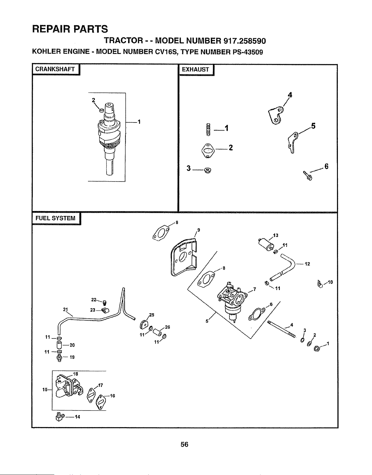
REPAIR PARTS
TRACTOR -- MODEL NUMBER 917.258590
KOHLER ENGINE - MODEL NUMBER CV16S, TYPE NUMBER PS-43509
CRANKSHAFT I
"_k'l_ '11.....................................
5
1I /
56
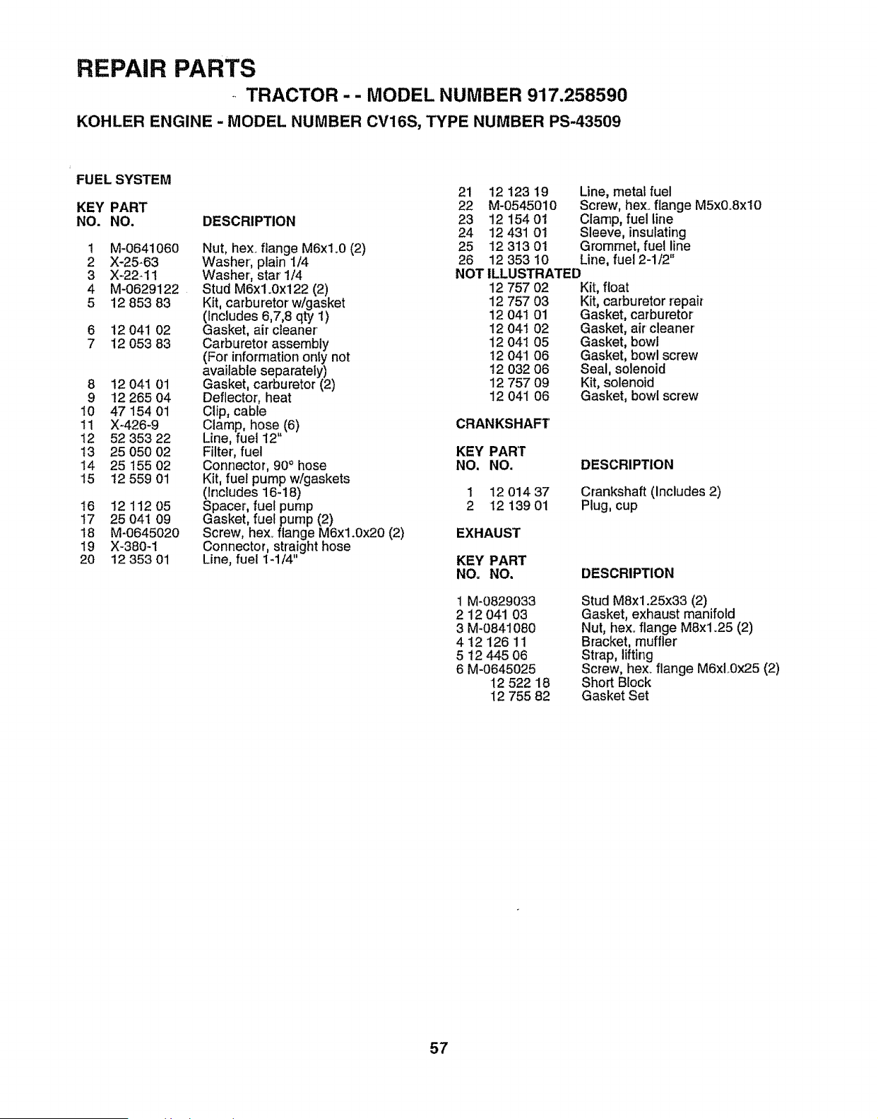
REPAIR PARTS
TRACTOR-- MODEL NUMBER 917.258590
KOHLER ENGINE - MODEL NUMBER CV16S, TYPE NUMBER PS-43509
FUEL SYSTEM
KEY PART
NO, NO. DESCRIPTION
t M-0641060
2 X-25-63
3 X-22-11
4 M-0629122
5 12 853 83
6 12 041 02
7 12 053 83
8 12 04I 01
9 12 265 04
10 47 154 01
11 X_426-9
12 52 353 22
t3 25 050 02
14 25 !55 02
15 12 559 01
t6 12 112 05
17 25 04I 09
18 M-0645020
19 X-380-1
20 12 353 01
Nut, hex. flange M6xl.0 (2)
Washer', plain 1/4
Washer, star 1/4
Stud M6x1.0x122 (2)
Kit, carburetor w/gasket
(Includes 6,7,8 qty 1)
Gasket, air cleaner
Carburetor assembly
(For informationonly not
available separately)
Gasket, carburetor (2)
Deflector, heat
Clip, cable
Clamp, hose (6)
Line, fuel 12"
Filter', fuel
Connector, 90 ° hose
Kit, fuel pump w/gaskets
(Includes 16-18)
Spacer, fuel pump
Gasket, fuel pump (2)
Screw, hex. flange M6xl.0x20 (2)
Connector, straight hose
Line, fuel 1-1/4"
21 12 123 19 Line, metal fuel
22 M-0545010 Screw, hexoflange M5x0.8xl0
23 12 154 01 Clamp, fuel line
24 12 431 01 Sleeve, insulating
25 12 313 01 Grommet, fuel line
26 12 353 10 Line, fuel 2-1/2"
NOT ILLUSTRATED
12 757 02 Kit, float
12 757 03 Kit, carburetor repair
12 041 01 Gasket, carburetor
12 041 02 Gasket, air cleaner'
12 041 05 Gasket, bowl
12 041 06 Gasket, bowl screw
t2 032 06 Seal, solenoid
12 757 09 Kit, solenoid
12 041 06 Gasket, bowl screw
CRANKSHAFT
KEY PART
NO. NO, DESCRIPTION
1 12 01437 Crankshaft (Includes 2)
2 12 139 01 Plug, cup
EXHAUST
KEY PART
NO, NO. DESCRIPTION
1 M-0829033
2 12 041 03
3 M-0841080
4 t2 12611
5 12 445 O6
6 M-0645025
12 52218
12 755 82
Stud M8x1.25x33 (2)
Gasket, exhaust manifold
Nut, hexoflange M8xl _25 (2)
Bracket, muffler
Strap, lifting
Screw, hex_flange M6xL0x25 (2)
Short Block
Gasket Set
57

SERVICE N
58

SUGGESTED GUIDE FOR SIGHTONG SLOPES FOR SAFE OPERATION
ONLY RIDE UP AND DOWN HILL,
NOT ACROSS HILL
SIGHT AND HOLD THIS LEVEL WITH
SKY LINE OR TREE.
I
15° MAX.
IIIIIIIII1!1111 I[ 'IIIIIIIIJJLILIIIIIUIJ[ ' iiiiiiii I I III III1'11 I
._ Operate your Tractor up and down the face of slopes (not I
U AA qreater than 15°), never across the face. Make turns gradu- |
_ ally to prevent tipping or !oss of control. Exercise extreme |
, caution when changing di,!ection on slopes, i
.... , ....... : ................. ,...........:,,,,, !_!
OWNER'S
MANUAL
t
MODEL NO.
917.258590
IF YOU NEED
REPAIR SERVICE
OR PARTS:
FOR REPAIR SERVICE, CALL
THIS TOLL FREE NUMBER:
1-800-4-REPAIR
(1-800-473-7247)
FOR REPLACEMENT PARTS
INFORMATION AND
ORDERING, CALL THIS
TOLL FREE NUMBER:
1-800-FON-PART
(1-800-366-7278)
FOR CONSUMER ASSISTANCE
HOT LINE, CALL THIS
TOLL FREE NUMBER:
1-800-659-5917
157286 Rev. 1 02125.97 JH
CRAFTSMAN°
16 HP
ELECTRIC START
46" MOWER
AUTOMATIC(HYDROSTATIC)
LAWN TRACTOR
Each tractor has its own model number. Each engine has
its own model number°
The model number for your tractor will be found on the
model plate located under the seal
The model number for your engine will be found on the
bEowerhousing of the engine.
All parts listed herein may be ordered from any Sears,
Roebuck and Con Service Center/Department and most Re-
tail Stores.
WHEN ORDERING REPAIR PARTS, ALWAYS GIVE THE
FOLLOWING INFORMATION:
• PRODUCT" TRACTOR
" MODEL NUMBER - 917.258590
• ENGINE MODEL NO. " 0V16S-43509
• PART NUMBER
• PART DESCRIPTION
Your Sears merchandise has added value when you
consider Sears has service units nationwide staffed with
Sears trained technicians°°° professional technicians
specifically trained to insure that we meet our pledge to
you, we service what we sell
II IIIIIIIIIIIIIIIIIIIIIIIIIIIIIIIIIIllll
Printed in U,S.A_
• " II


