Loading ...
Loading ...
Loading ...
30 - English
Making Connections
pro.Bose.com
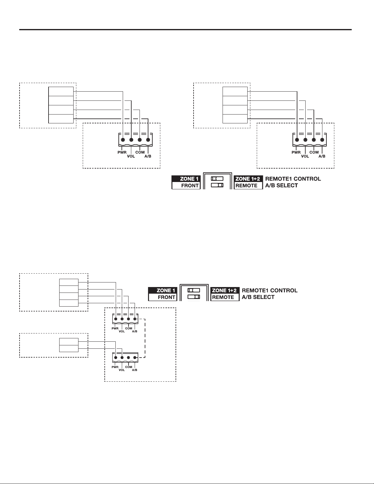
Configuration example 2
REMOTE 1 and REMOTE 2 can be a Bose volume control with A/B switch user interface (PC 041967) accessory.
REMOTE 1 will control the level and source selection of output one and REMOTE 2 will control the level and source
selection of output two. This configuration requires setting the REMOTE 1 CONTROL DIP switch to ZONE 1 and the A/B
SELECT DIP switch to REMOTE.
1 PW
R
2 VOL
3 CO
M
4 A/B
IZA 2120-HZ
Bose
volume
control
with
A/B
switch
REMOTE 1
DIP switch settings
1 PW
R
2 VOL
3 CO
M
4 A/B
IZA 2120-HZ
Bose
volume
control
with
A/B
switch
REMOTE 2
Configuration example 3
REMOTE 1 can be a Bose volume control with A/B switch user interface accessory (PC 041967) and REMOTE 2 can
be a volume control user interface accessory (PC 041966). In this configuration, REMOTE 1 controls the level of output
one and the source selection for both outputs. REMOTE 2 controls the level for output two. The A/B pin from REMOTE
1 needs to be jumpered with wire to the A/B pin on REMOTE 2. This configuration requires setting the REMOTE 1
CONTROL DIP switch to ZONE 1 and the A/B SELECT DIP switch to REMOTE. If the A/B jumper wire is not connected,
output two will default to amplifying input B constantly. If output two is to amplify input A constantly, the A/B pin of
REMOTE 2 needs to be jumpered to the COM pin. This configuration also works with the remote types reversed with a
volume control user interface accessory (PC 041966) on REMOTE 1 and a volume control with A/B switch user interface
accessory (PC 041967) on REMOTE 2.
1 PW
R
2 VOL
3 CO
M
4 A/B
1 PW
R
2 VOL
Bose volume
control with
A/B switch
Bose volume
control
IZA 2120-HZ
REMOTE 1
REMOTE 2
Jumper
wire
DIP switch settings
Loading ...
Loading ...
Loading ...