INSTRUCTION MANUAL
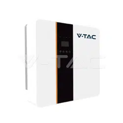
HYBRID SOLAR INVERTER SINGLE PHASE
IN CASE OF ANY QUERY/ISSUE WITH THE PRODUCT, PLEASE REACH OUT TO US AT: SUPPORT@V-TAC.EU
FOR MORE PRODUCTS RANGE, INQUIRY PLEASE CONTACT OUR DISTRIBUTOR OR NEAREST
DEALERS. V-TAC EUROPE LTD. BULGARIA, PLOVDIV 4000, BUL.L.KARAVELOW 9B
Thank you for selecting and buying V-TAC Product. V-TAC will serve you
the best. Please read these instructions carefully & keep this user manual
handy for future reference. If you have any another query, please contact
our dealer or local vendor from whom you have purchased the product.
They are trained and ready to serve you at the best.
INTRODUCTION
Multi-Language Manual QR CODE
Please scan the QR code to access the manual
in multiple languages.
WARNING
1. Please make sure to turn off the power before starting the installation.
2. Installation must be performed by a qualified electrician.
• "Danger" indicates a hazardous situation which, if not avoided, will result in
death or serious injury.
• "Warning" indicates a hazardous situation which, if not avoided, could result
in death or serious injury.
• "Caution" indicates a hazardous situation which, if not avoided, could result
in minor or moderate injury..
• Danger to life due to high voltages in the inverter!
• All work must be carried out by qualified electrician.
• The appliance is not to be used by children or persons with reduced physical
sensory or mental capabilities, or lack of exrerience and knowledge, unless
they have been given supervision or instruction.
• Children should be supervised to ensure that they do not play with the
appliance.
• Danger of burn injuries due to hot enclosure parts!
• During operation, the upper lid of the enclosure and the enclosure body may
become hot.
• Only touch the lower enclosure lid during operation.
• Possible damage to health as a result of the effects of radiation!
• Do not stay closer than 20 cm to inverter for any length of time.
• Ensure input DC voltage ≤Max. DC voltage .Over voltage may cause perma-
nent damage to inverter or other losses, which will not be included in warran-
ty!
• Authorized service personnel must disconnect both AC and DC power from
inverter before attempting any maintenance or cleaning or working on any
circuits connected to inverter.
• Do not operate the in verter when the device is running
• Over-voltage protection with surge arresters should be provided when the PV
power system is installed.
• The grid connected inverter is not fitted with SPDs in both PV input side and
MAINS side.
• High leakage current! Earth connection essential before connecting supply.
Note!
• "Note" provides tips that are valuable for the optimal operation of our
product.
• Grounding the PV generator.
• Comply with the local requirements for grounding the PV modules and the PV
generator. It is recommends connecting the generator frame and other
electrically conductive surfaces in a manner which ensures continuous conduc-
tion and ground these in order to have optimal protection of system and
persons.
20
PAP

• Prior to the application, please read this section carefully to ensure correct and safe
application. Please keep the user manual properly.
• Accesories only together with the inverter shipment are recommended here. Otherwise
may result in a risk of fire, electric shock, or injury to person.
• Make sure that existing wiring is in good condition and that wire is not undersized.
• Do not disassemble any parts of inverter which are not mentioned in installation guide.
It contains no user-serviceable parts. See Warranty for instructions on obtaining service.
Attempting to service the inverter yourself may result in a risk of electric shock or fire
and will void your warranty.
• Keep away from flammable, explosive materials to avoid fire disaster. The installation
place should be away from humid or corrosive substance.
• Authorized service personnel must use insulated tools when installing or working with
this equipment.
• PV modules shall have an IEC 61730 class A rating.
• Never touch either the positive or negative pole of PV connecting device.
• Strictly prohibit touching both of them at the same time.
• The unit contains capacitors that remain charged to a potentially lethal voltage after the
MAINS , battery and PV supply has been disconnected.
• Hazardous voltage will present for up to 5 minutes after disconnection from power
supply.
• CAUTION-RISK of electric shock from energy stored in capacitor, Never operate on the
inverter couplers, the MAINS cables, Battery cables, PV cables or the PV generator when
power is applied. After switching o ffthe PV , battery and Mains, always wait for 5minutes
to let the intermediate circuit capacitors discharge before unpluging DC ,battery inplug
and MAINS couplers.
• When accessing the internal circuit of inverter, it is very important to wait 5 minutes
before operating the power circuit or demounting the electrolyte capacitors inside the
device. Do not open the device before hand since the capacitors require time sufficiently
discharge!
• Measure the voltage between terminals UDC+ and UDC- with a multi-meter(impedance
at least 1Mohm) to ensure that the device is discharged before beginning work (35VDC)
inside the device.
Surge protection devices (SPDs) for PV installation
• Lightning will cause a damage either from a direct strike or from surges due to a nearby
strike.
• Induced surges are the most likely cause of lightning damage in majority or installa-
tions, especially in rural areas where electricity is usually provided by long overhead lines.
Surge may be included on both the PV array conduction and the AC cables leading to the
building.
• Specialists in lightning protection should be consulted during the end use application.
Using appropriate external lightning protection, the effect of a direct lightning strike into
a building can be mitigated in a controlled way, and the lightning current can be
discharged into the ground.
• Installation of SPDs to protect the inverter against mechanical damage and excessive
stress include a surge arrester in case of a building with external lightning protection
system (LPS) when separation distance is kept.
• To protect the DC system, surge suppression device (SPD type2) should be fitted at the
inverter end of the DC cabling and at the array located between the inverter and the PV
generator, if the voltage protection level (VP) of the surge arresters is greater than
1100V, an additional SPD type 3 required for surge protection for electrical devices.
• To protect the AC system, surge suppression devices (SPD type2) should be fitted at the
main incoming point of AC supply (at the consumer's cutout),located between the
inverter and the meter/distribution system; SPD (test impulse D1) for signal ine accord-
ing l to EN 61632-1.
• All DC cables should be installed to provide as short a run as possible, and positive and
negative cables of the string or main DC supply should be bundled together.

• Avoiding the creation of loops in the system.
• Spark gap devices are not suitable to be used in DC circuits once conducting, they won't
stop conducting until the voltage across their terminals is typically more than 30 volts.
• Anti-Islanding Effect Islanding effect is a special phenomenon that grid-connected PV
system still supply power to the nearby grid when the voltage loss is happened in the
power system. It is dangerous for maintenance personnel and the public. X1-Hybrid
series inverter provide Active Frequency Drift(AFD) to prevent islanding effect.
PE Connection and Leakage Current
• The end-use application shall monitor the protective conductor by residual current
operated protective device (RCD) with rated fault current Ifn≤240mA which automatically
disconnects the device in case of a fault. The device is intended to connect to a PV
generator with a capacitance limit of approx 700nf.
• Incorrect grounding can cause physical injury, death or equipment malfunction and
increase electromagnetic.
• Make sure that grounding conductor is adequately sized as required by safety regula-
tions.
• Do not connect the ground terminals of the unit in series in case of a multiple installa-
tion. This product can cause current with a d.c component, Where a residual current
operated protective (RCD) or monitoring (RCM) device is used for protection in case of
direct or indirect contact, only an RCD or RCM of type B is allowed on the supply side of
this product. For United Kingdom
• The installation that connects the equipment to the supply terminals shall comply with
the requirements of BS 7671.
• Electrical installation of PV system shall comply with requirements of BS 7671 and IEC
60364-7-712.
• No protection settings can be altered.
• User shall ensur e that equipment is so installed, designed and operated to maintain at
all times compliance with the requirements of ESQCR22(1)(a). For Australia and New
Zealand
• Electrical installation and maintenance shall be conducted by licensed electrician and
shall comply with Australia National Wiring Rules. Battery Safety Instructions BD series
inverter should be worked with high voltage battery, for the specific parameters such as
battery type, nominal voltage and nominal capacity etc., please refer to section 4.3. As
accumulator batteries may contain potential electric shock and short-circuit current
danger, to avoid accidents that might be thus resulted, the following warnings should be
observed during battery replacement:
1: Do not wear watches, rings or similar metallic items.
2: Use insulated tools.
3: Put on rubber shoes and gloves.
4: Do not place metallic tools and similar metallic parts on the batteries.
5: Switch o ffload connected to the batteries before dismantling battery connection
terminals.
6: Only personal with proper expertise can carry out the maintenance of accumulator
batteries.
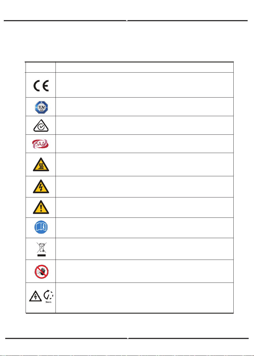
EXPLANATION OF SYMBOL
Symbol Explanation
CE mark.
The inverter complies with the requirements of the applicable CE
guildlines.
TUV certified.
RCM remark.
SAA certification.
Beware of hot surface. The inverter can become hot during operation.
Avoid contact during operation.
Danger of high voltages. Danger to life due to high voltages in the
inverter!
Danger.
Risk of electric shock!
The inverter can not be disposed together with the household waste.
Disposal information can be found in the enclosed documentation.
Do not operate this inverter until it is isolated from battery, mains
and on-site PV generation suppliers.
Danger to life due to high voltage. There is residual voltage existing
in the inverter after powering off, which needs 5 min to discharge.
• Wait 5 min before you open the upper lid or the DC lid.
Observe enclosed documentation.
This chapter follows the requirements of the European low voltage directives, which
contains the safety instructions and conditions of acceptability for the endues system,
which you must follow when installing, operating and servicing the unit. If ignored, physical
injury or death may follow, or damage may occur to the unit. Read this before you work on
the unit. If you are unable to understand the dangers, warnings, cautions or instructions,
please contact an authorized service dealer before installing. Operating and servicing the
unit. The Grid connected inverter meets the requirement stipulated in Low Voltage Directive
(LVD) 2014/35/EU and Electromagnetic Compatibility (EMC) Directive 2014/30/EU. The unit
is based on: EN 62109-1:2010;EN 62109-2:2011;IEC 62109-1(ed.1);
IEC62109-2(ed.1);EN 61000-6-3:2007+A:2011;EN 61000-6-1:2007;EN 61000-6-2:2005.
In case of installation in PV system, startup of the unit (i.e. start of designated operation)
is prohibited until it is determined that the full system meets the requirements stipulated in
EC Directive (2014/35/EU,2014/30/EU, etc.),The grid connected inverter leave the factory
completely connecting device and ready for connection to the mains and PV supply ,the
unit shall be installed in accordance with national wiring regulations. Compliance with
safety regulations depends upon installing and configuring system correctly, including using
the specified wires. The system must be installed only by professional assemblers who are
familiar with requirements for safety and EMC. The assembler is responsible for ensuring
that the end system complies with all the relevant laws in the country where it is to be
used. The individual subassembly of the system shall be interconnected by means of the
wiring methods outlined in national/inter national such as the national electric code (NFPA)
No.70 or VDE regulation 0107.
INTRODUCTION
Hybrid Inverter series is a high quality inverter which can convert solar ene rgy to AC
energy and store energy into battery
The inverter can be used to optimize self consumption, store in the battery for future use or
feedin to public grid. Work mode depends on PV energy and user's preference. It can
provide power for emergency use during the grid lost by using the energy from battery and
inverter(generated from PV).
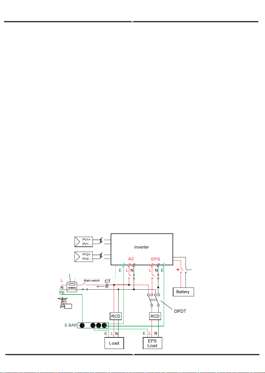
System Diagram 1 (applies to most countries )
meter
• Ensure input DC voltage ≤Max. DC voltage .Over voltage may cause perma
MAINS side.
Note!
• "Note" provides tips that are valuable for the optimal operation of our
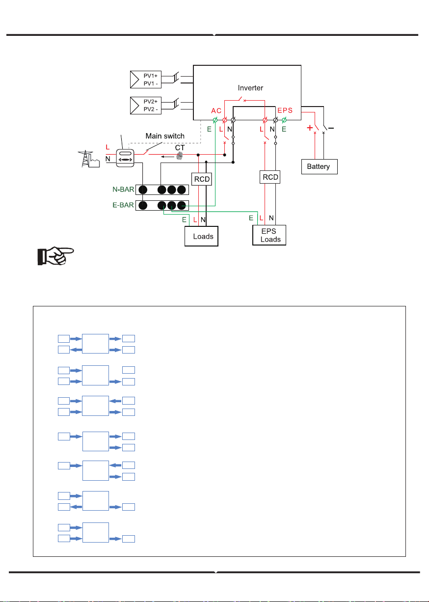
System Diagram 2 (applies to wiring rules AS/NZS_3000:2012 for Australia and New Zealand )
Note!
• The instrument and switch in the above figure are provided by users
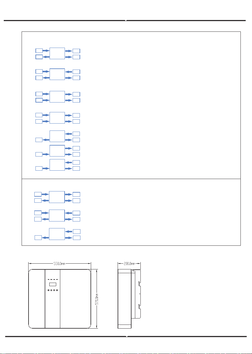
Hybrid Inverter provides multiple work modes based on different requirements.
Work Modes
meter
Inverter
PV
Grid
EPS
Inverter
PV
Grid
EPS
Inverter
PV
BAT
EPS
Inverter
PV
BAT
EPS
1.When PV, Grid, Battery is available:
A. Solar energy provides power to the loads as first priority, if solar energy is
sufficient to power all connected loads, solar energy excess power will
provides to charge battery, and then redundant power will feed to grid.
B. Solar energy provides power to the loads as first priority ,if solar energy is
not sufficient to power all connected loads, battery energy will supply power to the
loads at the same time.
C. Solar energy provides power to the loads as first priority ,if solar energy and
battery are not sufficient to power all connected loads, utility energy (Main Grid)
will supply power to the loads with solar energy at the same time.
2 .When PV, Grid is available(without battery):
A. Solar energy provides power to the loads as first priority ,if solar energy is
sufficient, the excess power will feed to grid.
B. Solar energy provides power to the loads as first priority, if solar energy is not
sufficient to power all connected loads, Grid energy will supply power to the loads
at the same time.
3 .When PV, Battery is available(Grid is disconnected):
A. Solar energy provides power to the loads as first priority ,if solar energy is
sufficient to power all connected loads, solar energy will provides to chargeb
battery.
B. Solar energy provides power to the loads as first priority ,if solar energy is not
sufficient to power all connected loads, battery energy and solar energy will supply
power to the loads at the same time.
Inverter
PV
BAT
Grid
EPS
Inverter
PV
BAT
Grid
EPS
Inverter
PV
BAT
Grid
EPS
Work modes : Self-use
Make sure that existing wiring is in good condition and that wire is not undersized.
Never touch either the positive or negative pole of PV connecting device.
MAINS , battery and PV supply has been disconnected.
CAUTION-RISK of electric shock from energy stored in capacitor, Never operate on the
inverter couplers, the MAINS cables, Battery cables, PV cables or the PV generator when
power is applied. After switching o ffthe PV , battery and Mains, always wait for 5minutes
and MAINS couplers.
Measure the voltage between terminals UDC+ and UDC- with a multi-meter(impedance
at least 1Mohm) to ensure that the device is discharged before beginning work (35VDC)
system (LPS) when separation distance is kept.
To protect the DC system, surge suppression device (SPD type2) should be fitted at the
generator, if the voltage protection level (VP) of the surge arresters is greater than
To protect the AC system, surge suppression devices (SPD type2) should be fitted at the
main incoming point of AC supply (at the consumer's cutout),located between the
inverter and the meter/distribution system; SPD (test impulse D1) for signal ine accord
ing l to EN 61632-1.
DIMENSION
1.When PV, Grid, Battery is available:
A. On charge time, solar energy will charge battery as first priority. The excess
energy will supply power to the loads.If solar energy is sufficient to supply loads
and charge battery,and If there's still some extra energy, then the excess power
will feed the power to grid
B. On charge time, solar energy will charge battery as first priority.then the excess
solar energy will supply power to loads.If solar energy is not sufficient to charge
battery and supply loads, grid will supply all the connected loads with solar energy
together.
C. On discharge time, solar energy provides power to the loads as first
priority, if solar energy is sufficient to supply loads ,and if there's still some
extra energy from solar energy ,then the excess power and battery will
deliver the power to the grid at the same time.
D. In the period of no charge or discharge, the solar power supply loads at
first priority , excess energy to the grid.
2. When Grid, Battery is available(PV is disconnected):
A. On charge time, grid will charge battery and supply power to the
connected loads at the same time.
B. On discharge time, if load power is less than battery power, battery will
supply power to loads as first priority, the excess power will be feed to grid.
C. On discharge time, if load power is more than battery power, battery and
grid will supply power to the loads at the same time.
Work modes : Peak shift
1.When PV, Grid, Battery is available:
A. Solar energy will charge battery as first priority, if solar energy is excess,
the excess power will supply load. If there's still some extra energy, then the
excess power will feed the power to grid .
B. Solar energy will charge battery as first priority, if solar energy is excess,
the excess power will supply load.If solar energy is not sufficient to charge
battery and supply loads, grid will supply power to loads.
2. When Grid,Battery is available(PV is disconnected):
Grid will supply power to load and charge battery at the same time.
Work modes : Bat priority
Inverter
PV
BAT
EPS
Grid
Inverter
PV
BAT
EPS
Inverter
PV
BAT
EPS
Grid
Grid
Inverter
PV
BAT
EPS
Grid
Inverter
BAT
EPS
Grid
Inverter
BAT
EPS
Grid
Inverter
BAT
EPS
Grid
Inverter
BAT
EPS
Grid
Inverter
BAT
EPS
Grid
PV
Inverter
BAT
EPS
Grid
PV
• Spark gap devices are not suitable to be used in DC circuits once conducting, they won't
series inverter provide Active Frequency Drift(AFD) to prevent islanding effect.
operated protective device (RCD) with rated fault current Ifn≤240mA which automatically
• Make sure that grounding conductor is adequately sized as required by safety regula
operated protective (RCD) or monitoring (RCM) device is used for protection in case of
direct or indirect contact, only an RCD or RCM of type B is allowed on the supply side of
the requirements of BS 7671.
• Electrical installation of PV system shall comply with requirements of BS 7671 and IEC
60364-7-712.
• No protection settings can be altered.
all times compliance with the requirements of ESQCR22(1)(a). For Australia and New
shall comply with Australia National Wiring Rules. Battery Safety Instructions BD series
battery type, nominal voltage and nominal capacity etc., please refer to section 4.3. As
4: Do not place metallic tools and similar metallic parts on the batteries.
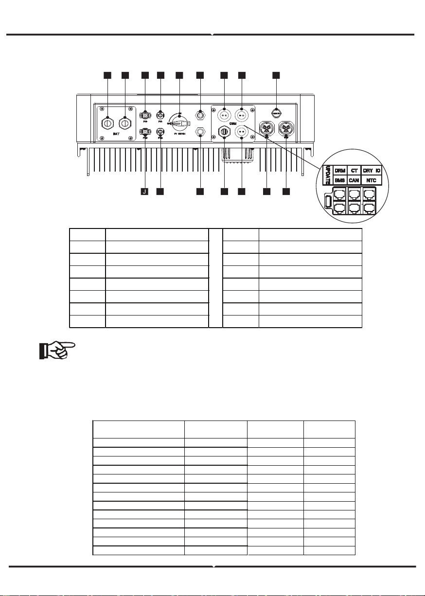
Note!
1.The Update port: For on-premises upgrades.
2.The BMS port: BMS communication for lithium batteries.
3.The CT port: For external grid side CT to detect current size.
4.The DRM port, CAN port, NTC port and DRY IO port: Reserved port,
temporarily unavailable
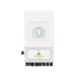
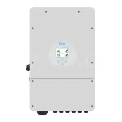
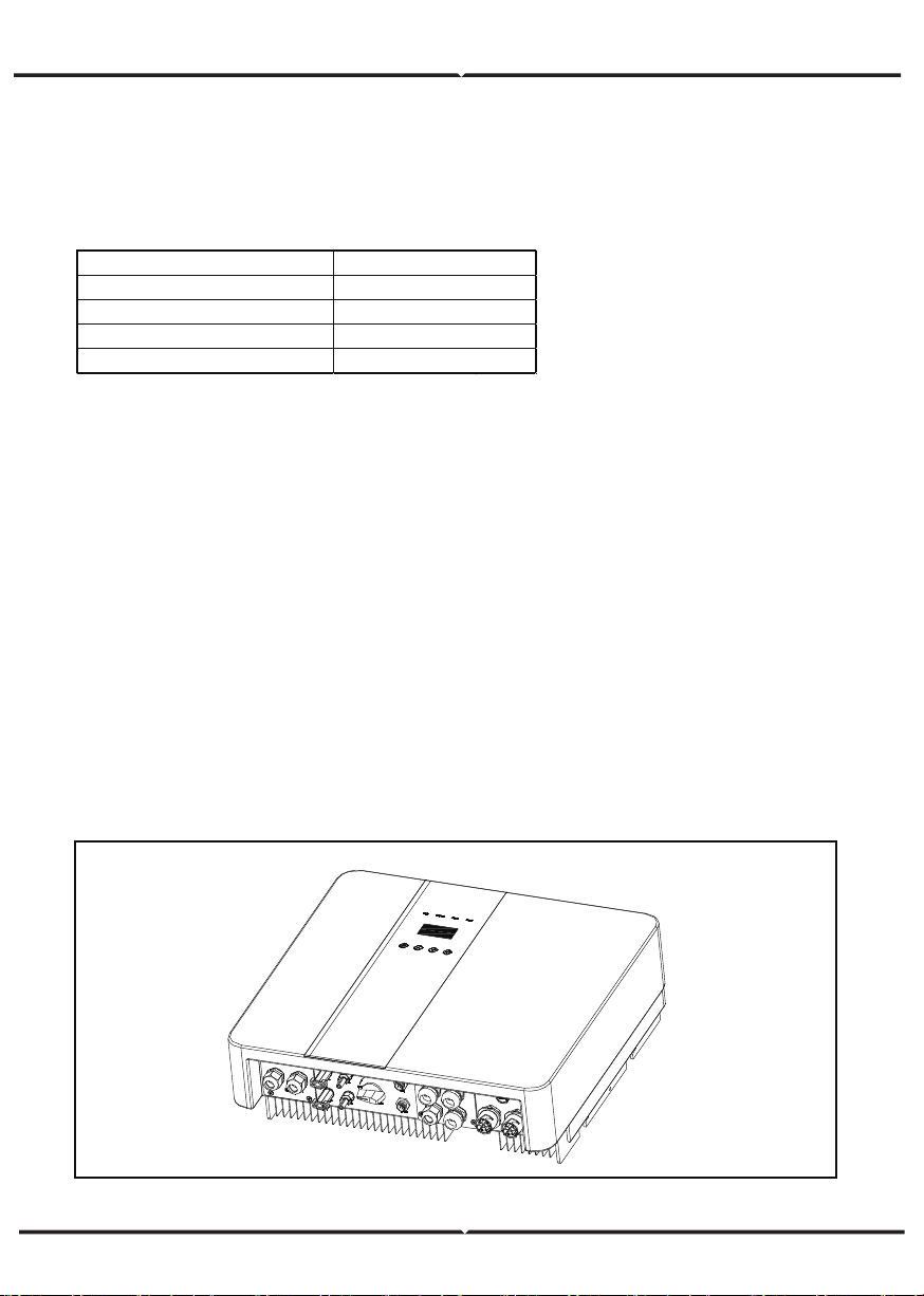
TERMINAL OF PV INVERTER
TECHNICAL DATA
1. DC input
Object Description Object Description
A/B Ba�ery +/Ba�ery - H Grid current / DRY IO
C/D PV1+/PV1- M USB port for upgrading
J/K PV2+/PV2- N POWER CAN /LEAD-NTC
E DC switch I Pressure valve
F WiFi port for external WiFi O EPS output
L Reserved port P Grid output
G DRM/BMS P Grid output
Max. recommended DC power [W] 4600
Max. DC voltage[V] 500
Norminal DC operating voltage[V] 360
MPPT voltage range [V] 125-500
MPPT voltage range@full load [V] 150-500
Max. input current [A] 14/14
Max. short circuit current [A] 14/14
Start input voltage [V] 125
Start output voltage [V] 150
No. of MPP trackers 2
Strings per MPP tracker 1
Backfeed current to PV array 0
DC disconnection swtich /
MODEL VT-66036103
4600
500
360
125-500
150-500
14/14
14/14
125
150
2
1
0
/
VT-66036103
4600
500
360
125-500
150-500
14/14
14/14
125
150
2
1
0
/
VT-66036103
A B
C D
E
F
G H I
M
A
K L
N
O
P
com
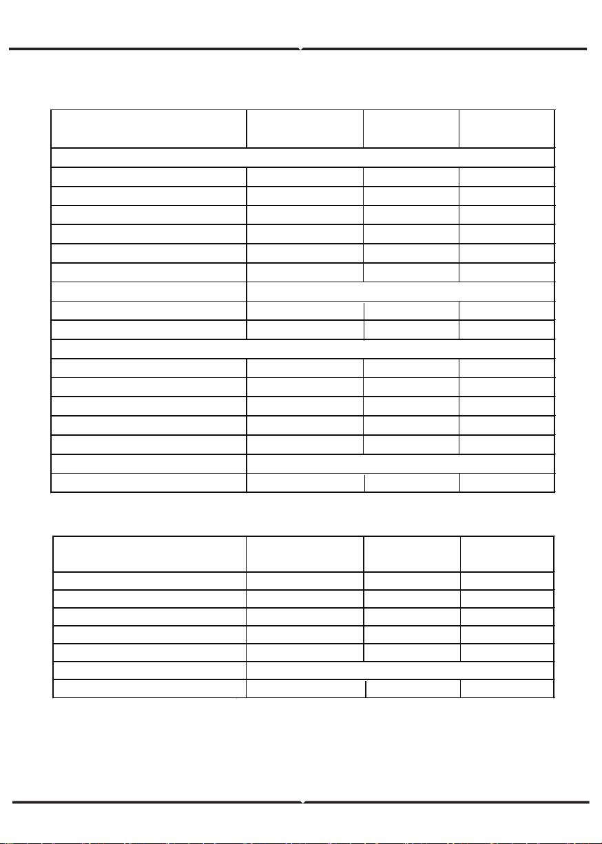
AC OUTPUT/INPUT
BATTERY PARAMETER
Norminal AC power[VA] 3000/3600
Max. apparent AC power[VA] 3000/3600
Rated grid voltage(range)[V] 230 (176 to 270)
Rated grid frequency[Hz] 50/60
Norminal AC current[A] 13/16
Max.AC current[A] 13/16
Displacement power factor 0.8 leading...0.8 lagging
Total harmonic distortion(THDI) < 2%
Load control optional
Norminal AC power[VA] 3000/3600
Rated grid voltage(range)[V] 230(176 to 270)
Rated grid frequency[Hz]
Norminal AC current[A] 13/16
50/60
Max.AC current[A] 13/16
Displacement power factor 0.8 leading...0.8 lagging
AC inrush current 35
MODEL
AC OUTPUT
VT-66036103
AC INPUT
Ba�ery type Lithium ba�ery
Ba�ery voltage range[V] 42-59
Recommended ba�ery voltage[V] 48
Max. charge/discharge current[A] 95/76.6
Peak charge/discharge current[A] 95/76.6
Communication interfaces CAN/RS485/WIfI/LAN/DRM
Reverse connect protection Yes
MODEL VT-66036103

Efficiency, Safety and Protection (apply to version E,I)
Efficiency, Safety and Protection (apply to version E,I)
MPPT efficiency 99.90%
Euro efficiency 97%
Max. efficiency 97.60%
Max. Ba�ery charge efficiency 95%
Max. Ba�ery discharge efficiency 95%
Over/under voltage protection YES
DC isolation protection YES
Monitoring ground fault protection YES
Grid protection YES
DC injection monitoring YES
Back feed current monitoring YES
Residual current detection YES
Anti-islanding protection YES
Over load protection YES
Over heat protection YES
VT-66036103
Safety & Protection
MODEL
EPS rated power[VA] 3000/3600
Max. EPS power[VA] 3000/3600
EPS rated voltage, Frequency 230VAC, 50/60Hz
EPS rated current[A] 13/16
Max. EPS current[A] 13/16
Switch time[s] <500ms
Total harmonic distortion(THDv) <2%
Parallel operation Yes
Compatible with the generator
Yes(signal provided only)
VT-66036103MODEL

General Data (apply to version E,I)
Dimension [W/H/D](mm) 550*520*200
Dimension of packing [W/H/D](mm) 665*635*330
Net weight [kg] 25
Gross weight [kg] 31
Installation Wall-mounted
Operating temperature range[
℃
] -25~+60 (derating at 45)
Storage temperature [
℃
] -25~+60
Storage/Operation relative humidity 4%~100% ( Conde nsi ng)
Altitude [m] <2000
Ingress Protection IP65(for outdoor use)
Protective Class Ⅰ
Night-time consumption <3W
Over Voltage Category Ⅱ(MAINS),Ⅱ( PV, Ba�ery)
Pollution Degree II
Cooling Nautral
Noise level <40dB
Inverter Topology non-isolated
Communication interface CAN/RS485/WIfI/LAN/DRM
VT-66036103MODEL
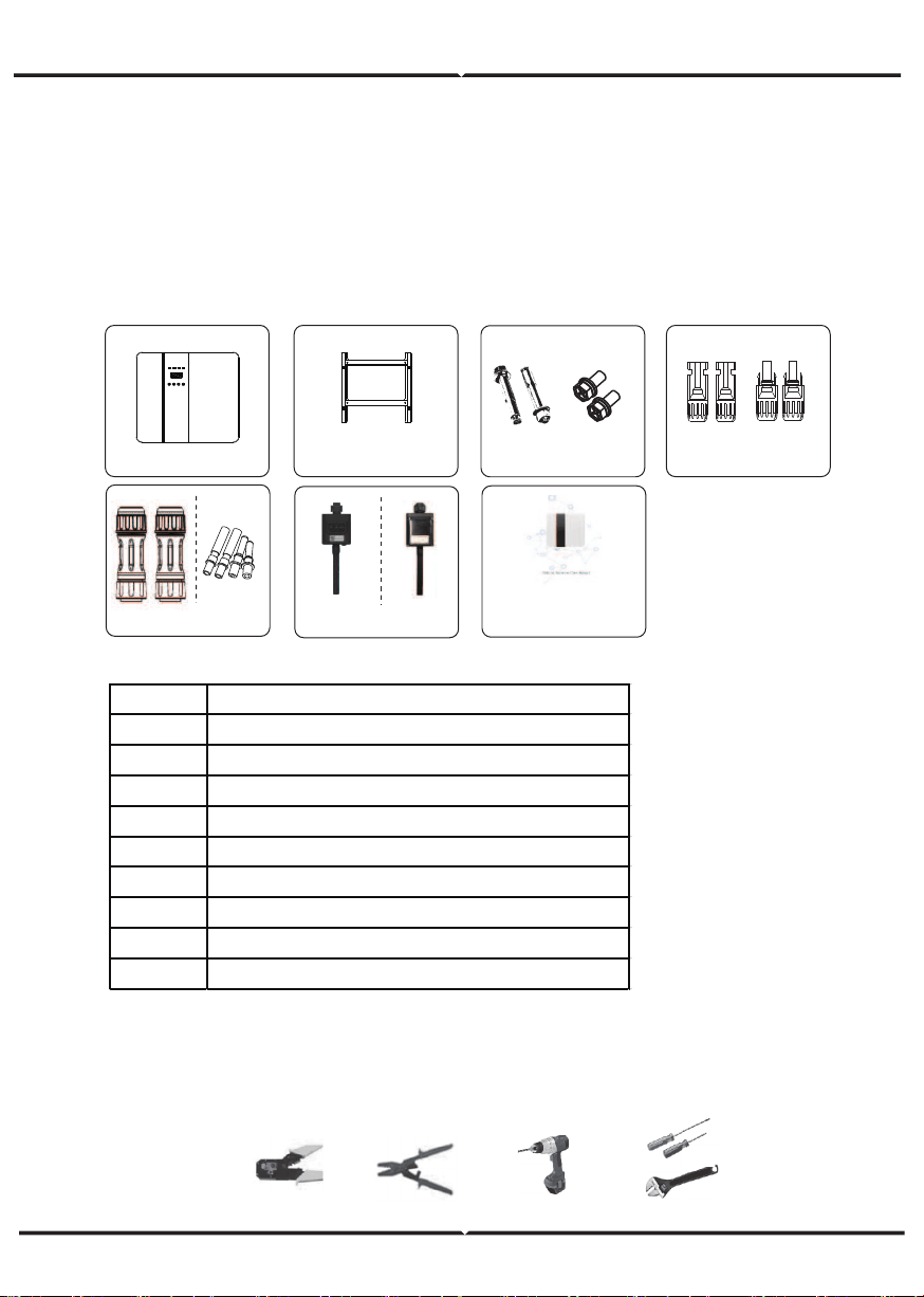
TOOLS REQUIRED FOR INSTALLATION
INSTALLATION
Check for Physical Damage Make sure the inverter is intact during transportation. If there
is any visible damage, such as cracks, please contact your dealer immediately.
PACKING LIST
Open the package and take out the product, please check the accessories first.
The packing list shown as below.
Installation tools: crimping pliers for binding post and RJ 45, screwdriver, manual wrench etc
Object Description
A Inverter
B Bracket
C Expansion screws and pan-head screws
D PV connectors (2*positive, 2*negative)
E AC terminals
F PV pin connectors (2*positive, 2*negative)
G Wifi module (optional)
H GPRS module (optional)
I User manual
B C D
E F
I
G
H
A
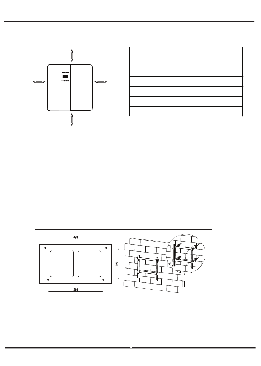
SPACE REQUIREMENT
Step 1: Screw the wall bracket on the wall
1.1. Place the bracket on the wall and mark down the position of the 4 holes.
1.2. Drill holes with driller, make sure the holes are deep enough (at least 60mm) to
support the inverter.
1.3. Install the expansion tubes in the holes, and tighten them. Then install the wall
bracket with the expansion screws.
Step 2: Place the inverter on the wall mounted bracket by holding the handle on the side.
Step 3: Tighten the fixing screws on both sides of the inverter.
Step 4: If necessary, costomer can install an anti-theft lock on the left-bottom of the
inverter.
Position Min.size
Left 300mm
Right 300mm
Top 300mm
Bo�om 300mm
Front 300mm
Table Available Space Size
300mm
300mm
300mm
300mm
Step 1
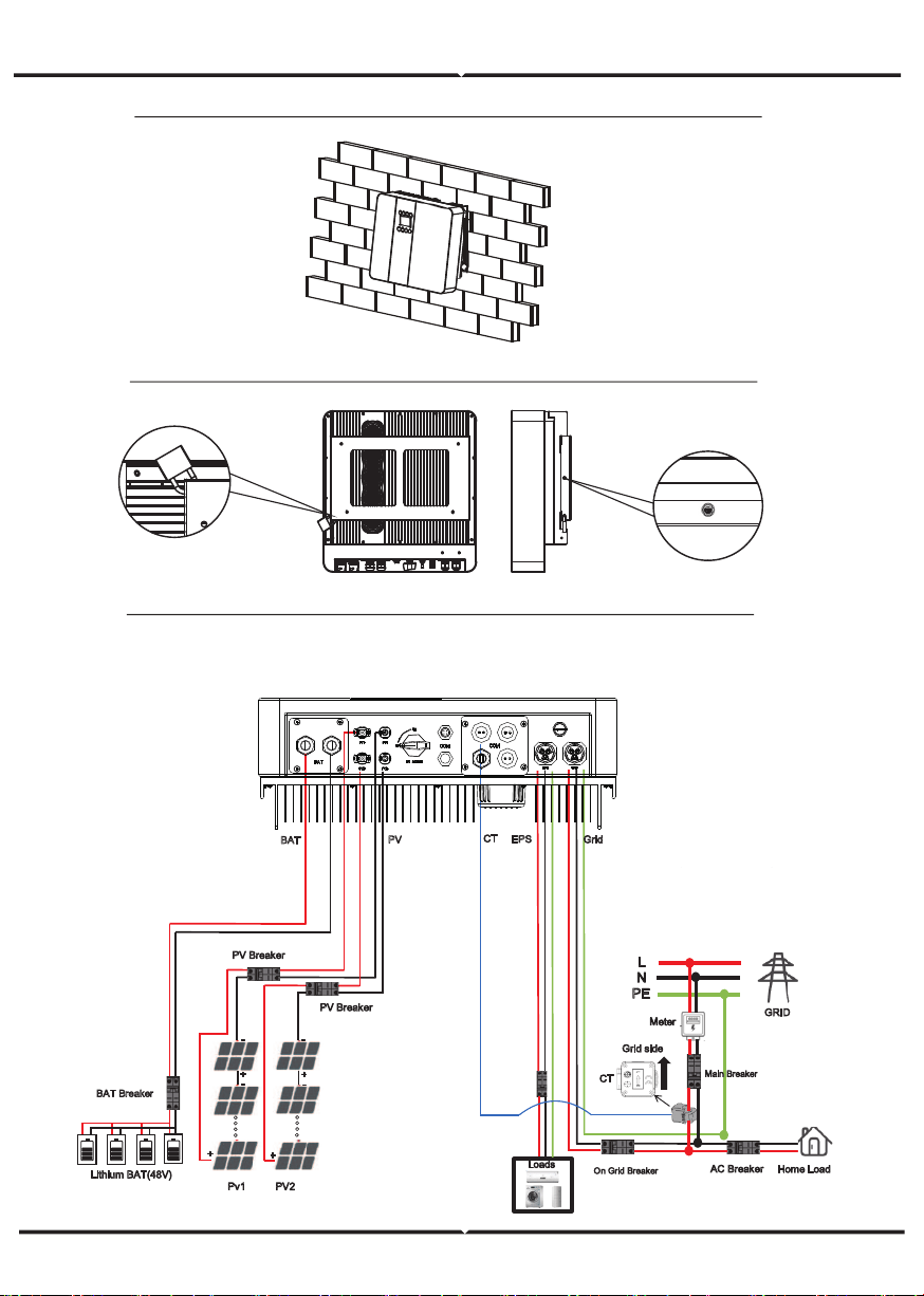
ELECTRICAL CONNECTION
Electrical connection diagram
Step 2
Step
4
Step 3,
GRID
L
N
PE
Grid side
Home Load
Meter
Main Breaker
AC Breaker
On Grid Breaker
CT
Pv1
PV2
PV Breaker
PV Breaker
Lithium BAT(48V)
BAT Breaker
(PV MAX:500V)
.
.
.
.
.
.
.
.
-
-
-
-
EPS
Grid
PV
BAT
Loads
EPS
Breaker
CT
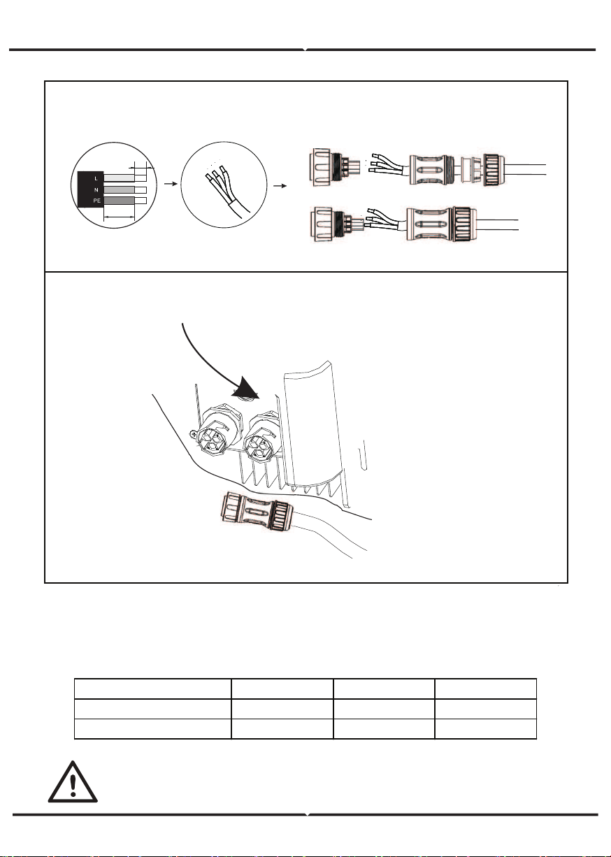
GRID CONNECTION AND EPS CONNECTION
Hybrid inverter are designed for single phase grid. Voltage is 220/230/240V, frequency is
50/60Hz. Other technical requests should comply with the requirement of the local public
grid.
Micro-breaker should be installed between inverter and grid, any load should not be
connected with inverter directly.
Step1. Check the grid voltage.
1.1 Check the grid voltage and compare with the permissive voltage range (Please refer to
technical data).
1.2 Disconnect the circuit board from all the phases and secure against re-connection.
Step2. Remove the waterproof lid from the grid port on the inverter.
Step3. Make AC and EPS wires.
3.1 Choose the appropriate wire(Cable size: refer to Table 1).
3.2 Reserve about 60mm of conductor material sectional area and remove 10mm of
insulation from the end of wire.
terminal and tighten the screws with a hexagonal wrench.
3.3 Separate the docking screw cap of the AC terminal from the housing portion and insert
stripped wires into AC
3.4 Tighten the docking screw cap and housing portion of the AC terminal.
Step4.
Connect the AC connector to the GRID port of the inverter and tighten the screw cap .
Connect the LOAD connector to the EPS port of the inverter and tighten the screw cap .
Table 1 Cable and Micro-breaker recommended
MODEL VT-66036103
E VERSION CABLE 4-5 mm²
E VERSION MICRO-BREAKER 20A
I VERSION CABLE 8-10mm²
I VERSION MICRO-BREAKER 50A
Step3
Step4
Cable Size: Refer to Tabel 4(page 24)
Note: Connect the AC connector to the GRID into grid interface.
60mm
10mm
EPS
GRID
PV CONNECTION
Select PV modules with excellent function and reliable quality. Open-circuit voltage of
module arrays connected in series should be <Max. DC input voltage;operating voltage
should be conformed to MPPT voltage range.
MODEL VT-66036103 VT-66036103 VT-66036103
Max. DC Voltage (V) 500 500 500
MPPT Voltage Range(V) 125-500 125-500 125-500
Warning!
PV module voltage is very high, which already achieve dangerous voltage range,
please comply with electric safety rules when connecting.
Please do not make PV positive or negative ground!
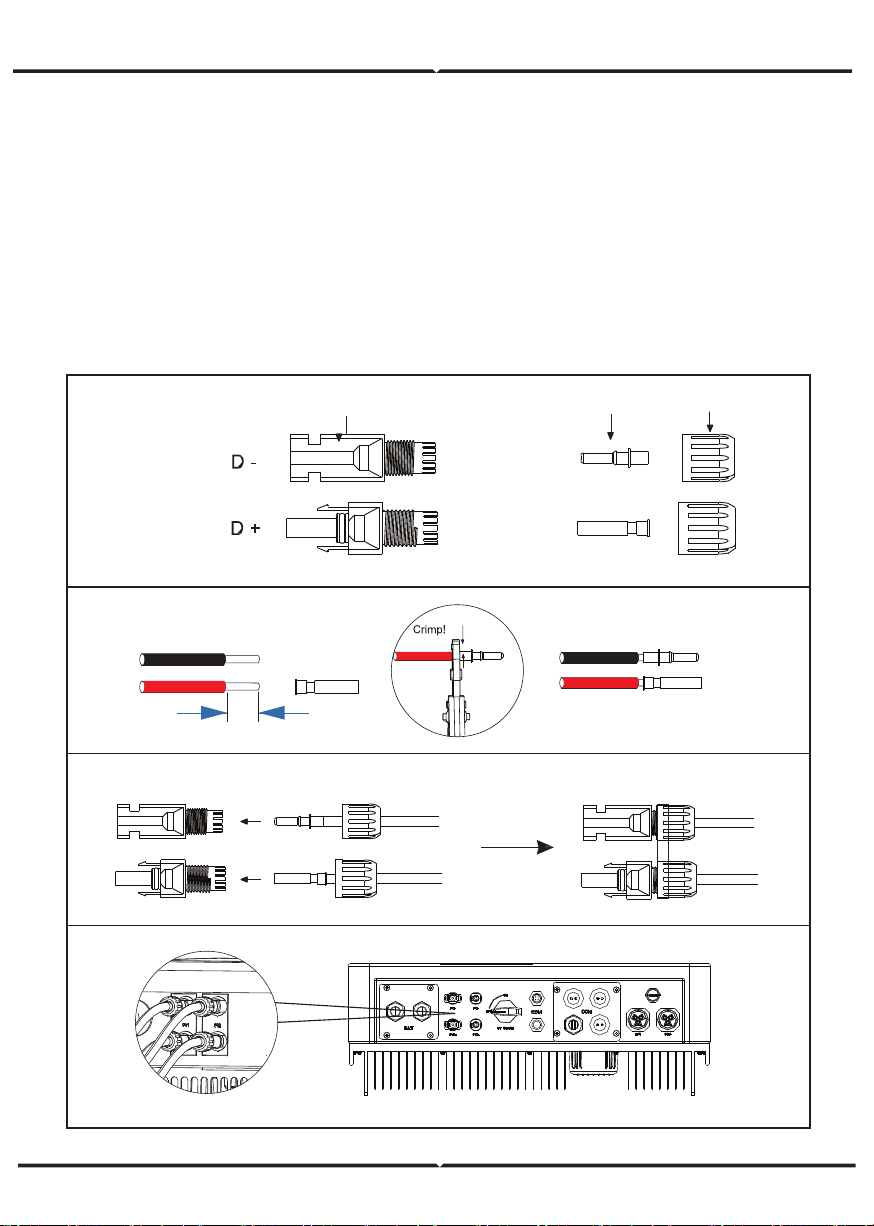
plug
pin contact cable nut
Step2
10mm
12AWG
insert
Step3
Step4
Step5
CONNECTION STEPS:
Step 1. Checking PV module to ensure PV is in open circuit state and ensure the PV+ and
PV- ports of the PV string are correct.
Step 2. Separating the DC connector.
Step 3. Wiring
3.1 Choose the 12 AWG wire to connect with the cold-pressed terminal.
3.2 Remove 10mm of insulation from the end of wire.
3.3 Insert the insulation into pin contact and use crimping plier to clamp it.
Step 4. Insert pin contact through the cable nut to assemble into back of the male or female
plug. When
you feel or heard a “click” sound the pin contact assembly is seated correctly.
Step 5. Plug the PV connector into the corresponding PV connector on inverter.
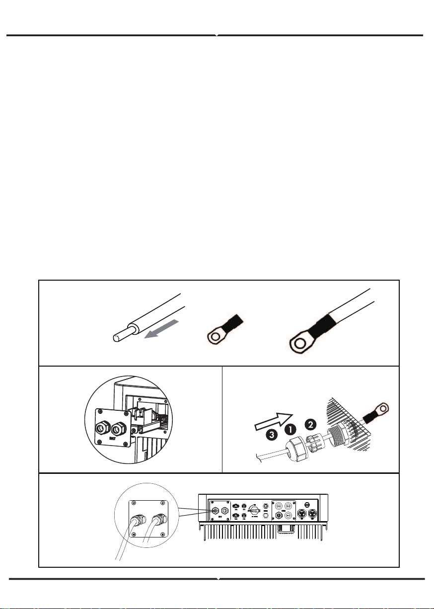
Battery Connection
Note
1.Before choosing battery, please note the maximum voltage of battery can not exceed 59V
and the rated voltage of battery can not exceed 48V, and the battery communication
should be compatible with Hybrid inverter.
2.Before connecting to battery, please install a nonpolarized DC(125A) breaker to make
sure inverter can be securely disconnected during maintenance.
3.The connecting cable between the battery and the inverter shall be at least 4AWG.
4.The battery communication can only work when the battery BMS is compatible with the
inverter.
5.To replace the battery, you need to turn off all switches and unplug the system communi-
cation line.
6.All the above wiring and operations must be carried out after the whole machine is
powered down, and all of them need professional personnel to complete
Power Connection Steps:
Step 1. Choose the 4AWG wire and strip the cable to 15mm.
Step 2. Select two O-terminals with an aperture of M6.
Step 3. Insert the stripping line into the O-terminal and clamp it with a crimping clamp.
Step 4. Remove waterproof cover plate.
Step 5. Disassemble the waterproof connector and pass the cable through the waterproof
connector.
Step 6. Connect the cable to the terminal of the inverter .
Step 7. Assemble waterproof connectors and waterproof covers plate.
Step1,2,3.
Step 4. Step 5.
Step 6, 7.
BAT
Note
Positive and negative lines are not allowed to reverse.
The positive pole on the left and the negative pole on the right.
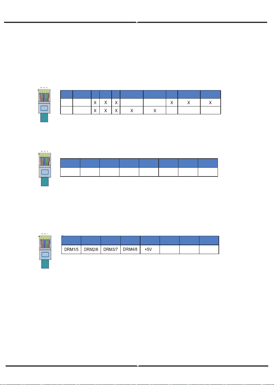
Communication interface definition
BMS PIN Definition
Communication interface between inverter and battery is RS485 or CAN with a RJ45
connector.
The wiring sequence of the crystal head conforms to the 568B standard: orange
white, orange, green white, blue, blue white, green, brown white and brown.
DRY_IO (RJ45 PIN) Definition
Reserved dry contact interface of the inverter.
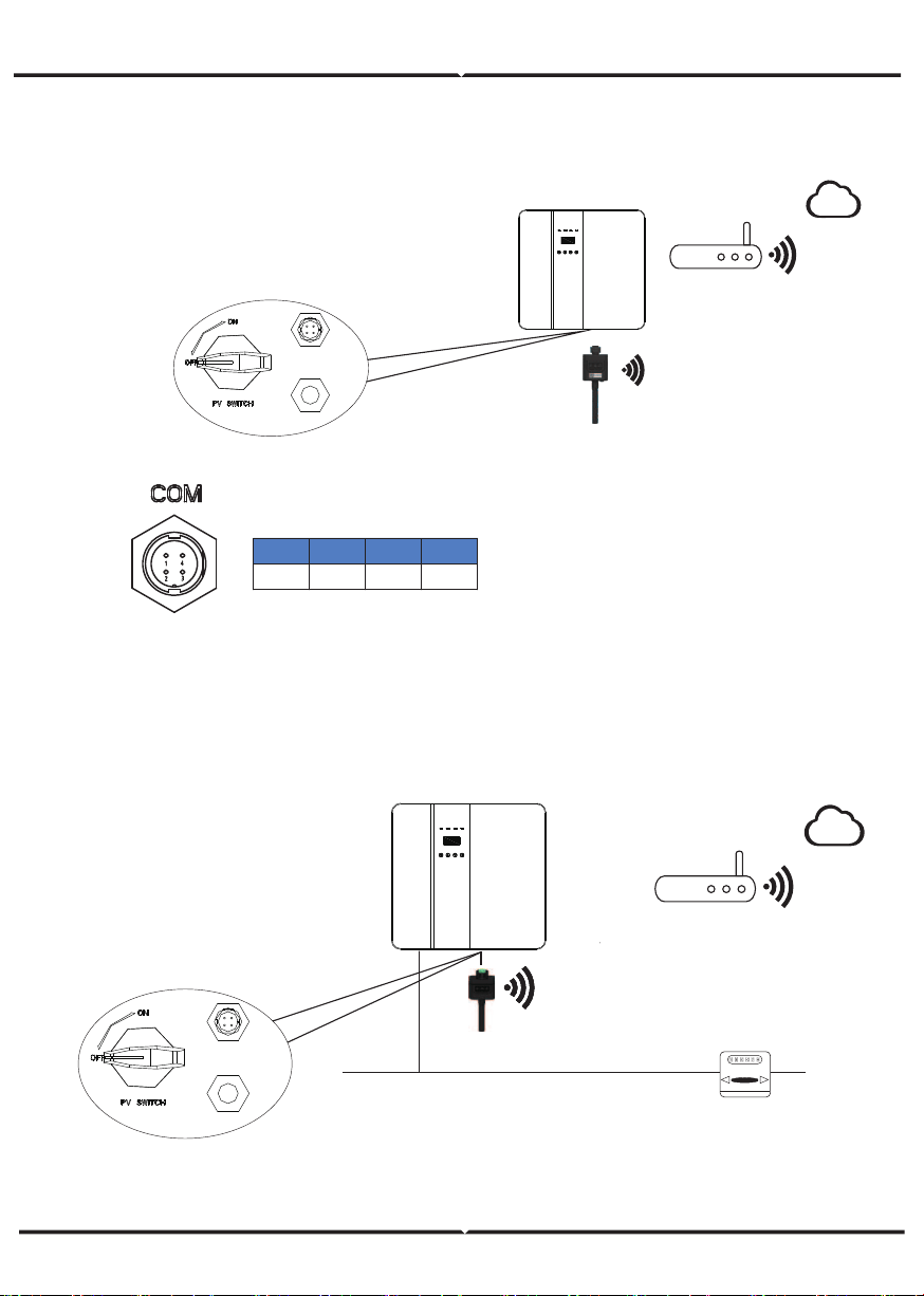
WiFi And GPRS Connection(optional)
Inverter provides a WiFi port which can collect data from inverter and transmit it to
monitoring-website by WiFi.
Step1. Plug Wifi into “COM” port at the bottom of the inverter.
Step2. Build the connection between the inverter and router.
Step3. Create a user account online. (Please check the WiFi user manual for more
details).
DRM Connection
DRM is provided to support several demand response modes by emitting control
signals as below.
Note: Only PIN6(DRM0) is available now, and other PIN functions are being devel-
oped.
1
8
BMS_CANH
BMS_CANL
Definition
2
3 4
5
6 7 81
PIN
BMS_485A
BMS_485B
GND
Definition
CAN
Rs485
.
1
8
DRM0 GND GND
1 2 3 4 5 6 7 8
1
8
COM1
NO 1
COM2
DI 1
DI 2
NC 1
NO 2
1 2 3 4 5 6 7 8
NC 2
DIAGRAM
GPRS CONNECTION
GPRS connection interface is consistent with WIFI interface,Please refer to the GPRS user
manual for detailed connection steps.
DIAGRAM
Could
Router
com
WiFi
+5V
RS485_A
RS485_B
GND
1 2 3 4
Grid
Meter
AC
GPRS
com
Could
Router
LCD INTERFACE AND SETTING
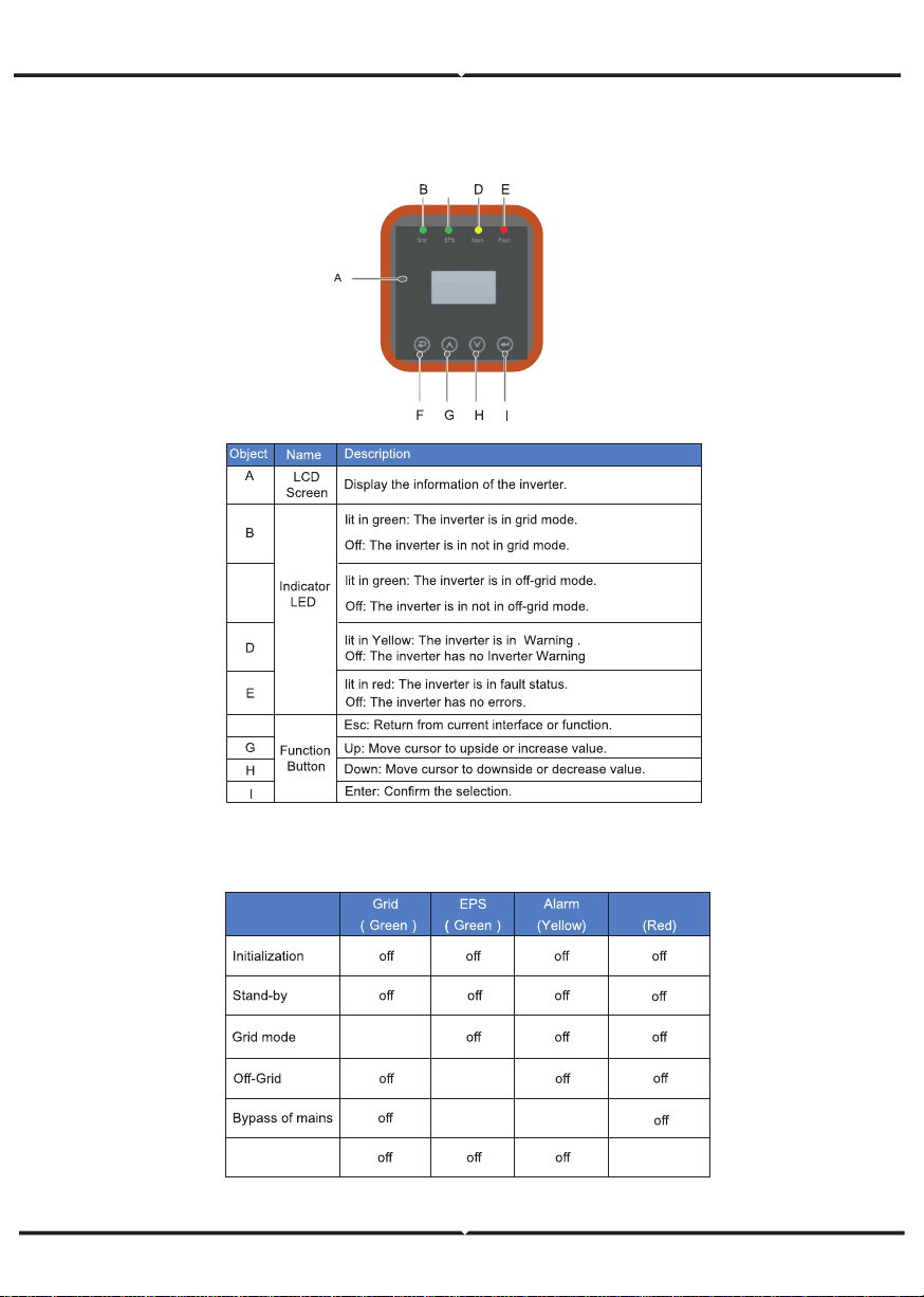
CONTROL PANEL
INSTRUCTIONS FOR LED INDICATOR
C
F
Fault
on
on
on
on
Fault
on
C
INSTRUCTIONS FOR THE USE OF THREE MODES
O
R
O
D
W
REM OTE CTRL
PEAK SHIFT
DC- SOURCE
Li t hum - 4 8V
(Test m o d e)
(Test m o d e)
48 5
14、
AUTO TEST
(It alian c er t i f icat io n )
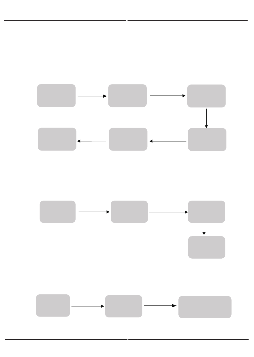
For example,Before selecting the mode, you can set it up ac cording to the local power
grid, PV input mode and battery type.
POWER GRID:
Select 1:Set up
Press Enter button
Press Esc button
Circular display
interface
Default password 00000
Press UP/DOWN button
Adjust the figure.
Press Enter button
Press Enter button
User
Enter password
3:GRID STD
Choose
according to
local power grid
Circular display
interface
PVINPUT MODE
:
BATTERY PARAMETERS:
Enter password
Enter password
Setting
1:SYS SETTING
Press Enter button
Press Enter button
6 PV INPUT
Select PV input
enter to confirm
Setting
Press Enter button
1:BAT TYPE
Set corresponding battery
type,Press enter to confirm.
Press Enter button
mode,Press
Press Enter button
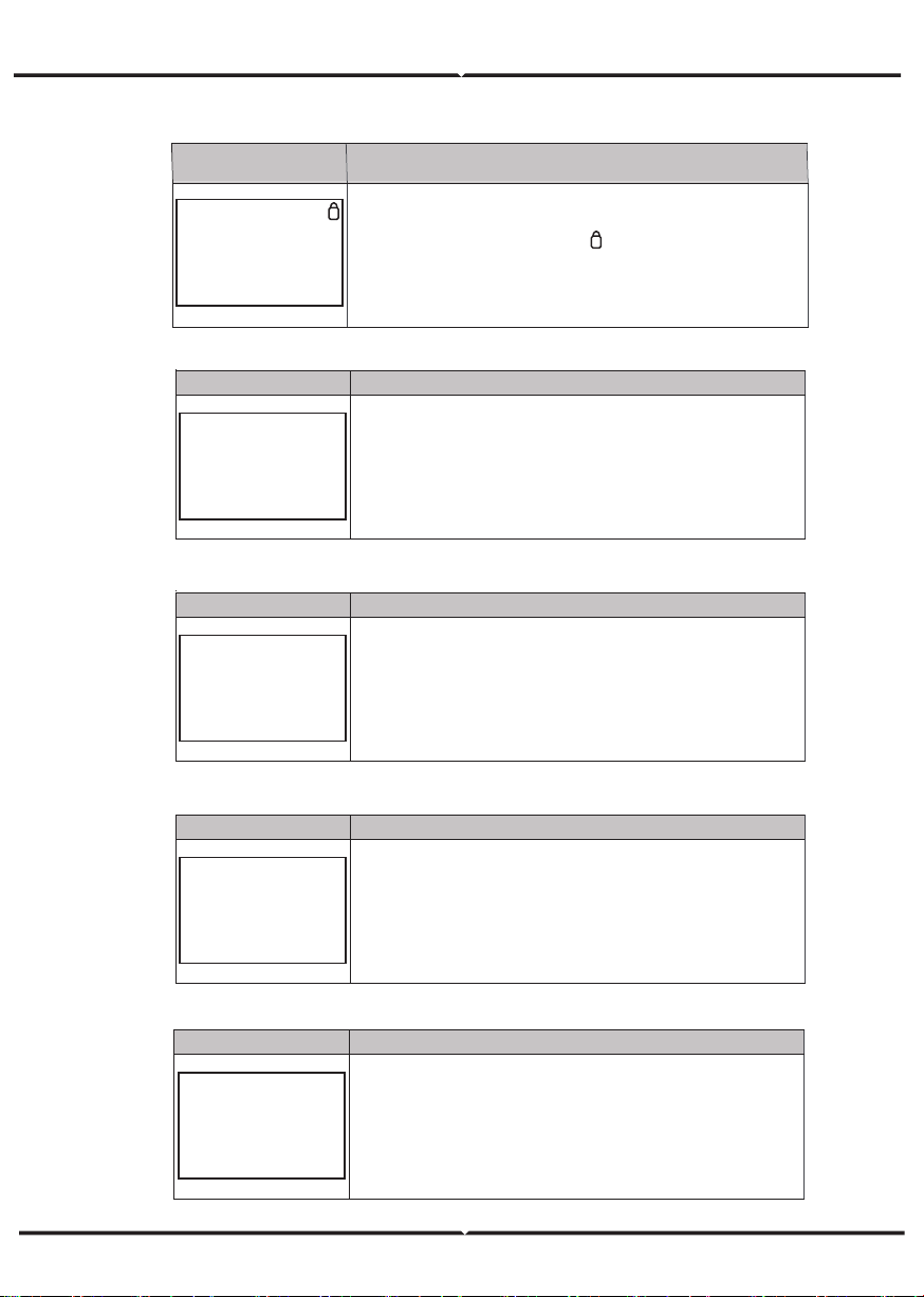
5.4.1 ERROR INFORMATION
Interface Description
ERROR NO.
02:BatDisconnect
27:BMS Comm.fail
Numbers represent error codes and text is error information.
Refer to Chapter 9 for specific contents.
NOTE: When there is a lock mark in the upper right corner of
the screen, you cannot turn the page, you need to press Enter to
unlock it first.
Interface Description
SYSTEM1
STATE: SELF CSM
GRID :
US-CA
PV I/P: PARALL
State: Setting of the whole machine working mode. Including:
SELF CONSUME, PEAK SHIFT and BAT PRIORITY.
Refer to Chapter 3.3 for specific contents.
Grid standard: Displays the grid standard actually set.
PV input mode: The display value is the setting value of PV
input type. Including: INDEPENDANT, PARALLEL, C V.
Interface Description
SYSTEM2
BMS Com: CAN
Anti Reve :
DISA
DOD: 80%
BMS Com: Battery Management System communication mode.
Including: CAN, RS485.
Anti Reve
: Displays Whether Inverter isn’t allowed to generate
electricity to the Grid. Including: DISABLE,ENABLE
DOD: Depth of battery discharge.
Interface Description
SYSTEM3
EPS ENABLE: ENAB
EPS ENABLE:
When the Grid and PV are powered off, Enable the
battery to supply power to the load, default option is enable.
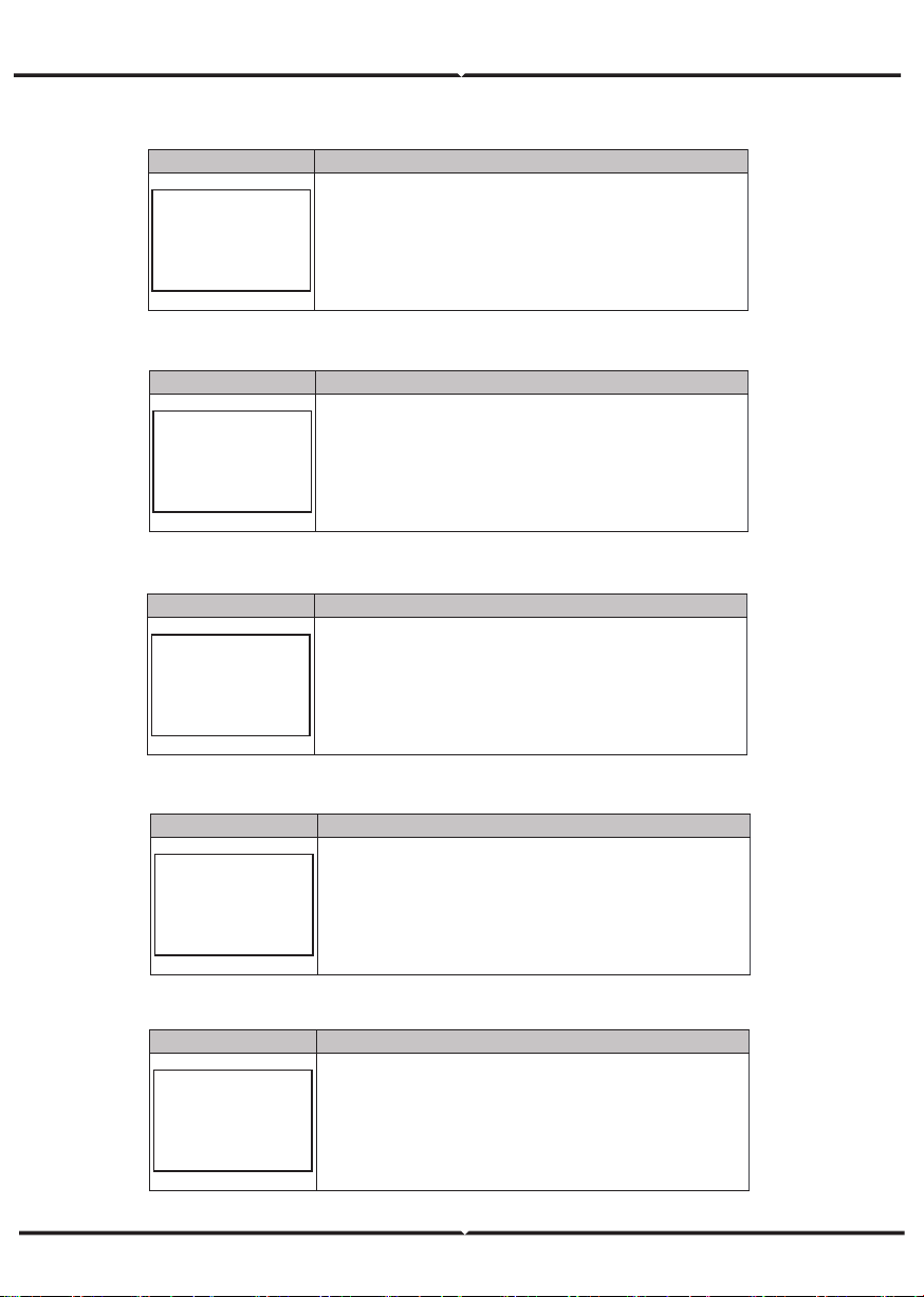
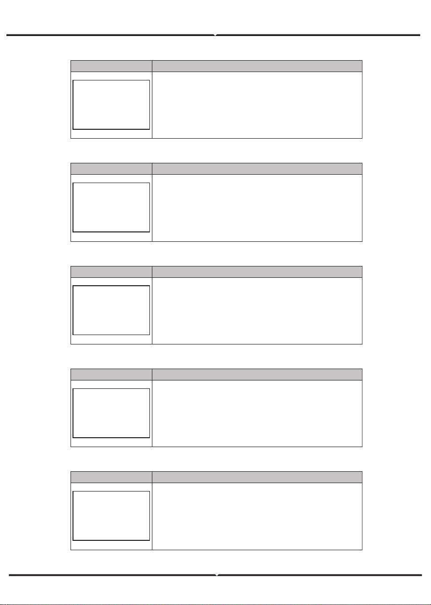
Interface Description
PV1 INPUT
VOLT: 300V
CURR:
10.00A
POWER: 3000W
PV1 input real-time voltage, current and power.
LCD INTERFACE
5.4.2 SYSTEM SETTING
5.4.3 SYSTEM SETTING2
5.4.4 SYSTEM SETTING3
5.4.5 PV1 INPUT DISPLAY INTERFACE
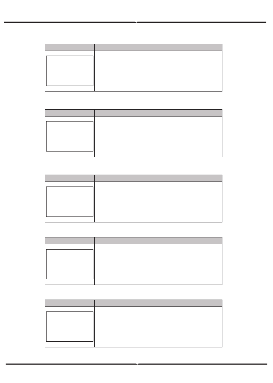
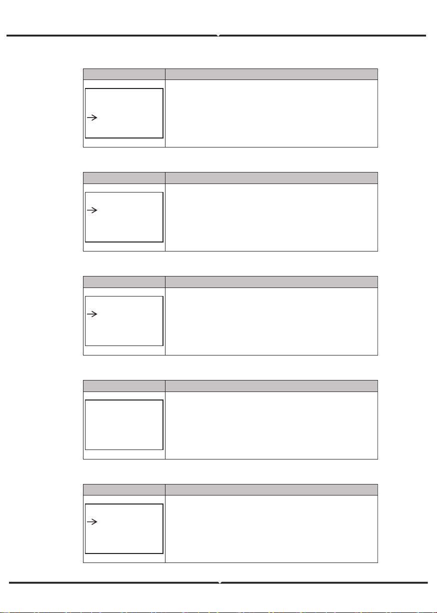
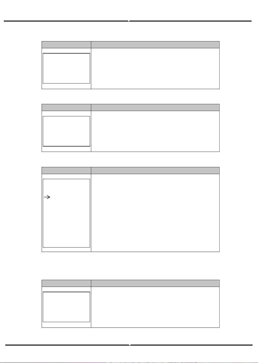
Interface Description
PV2 INPUT
VOLT: 300V
CURR:
10.00A
POWER: 3000W
PV2 input real-time voltage, current and power.
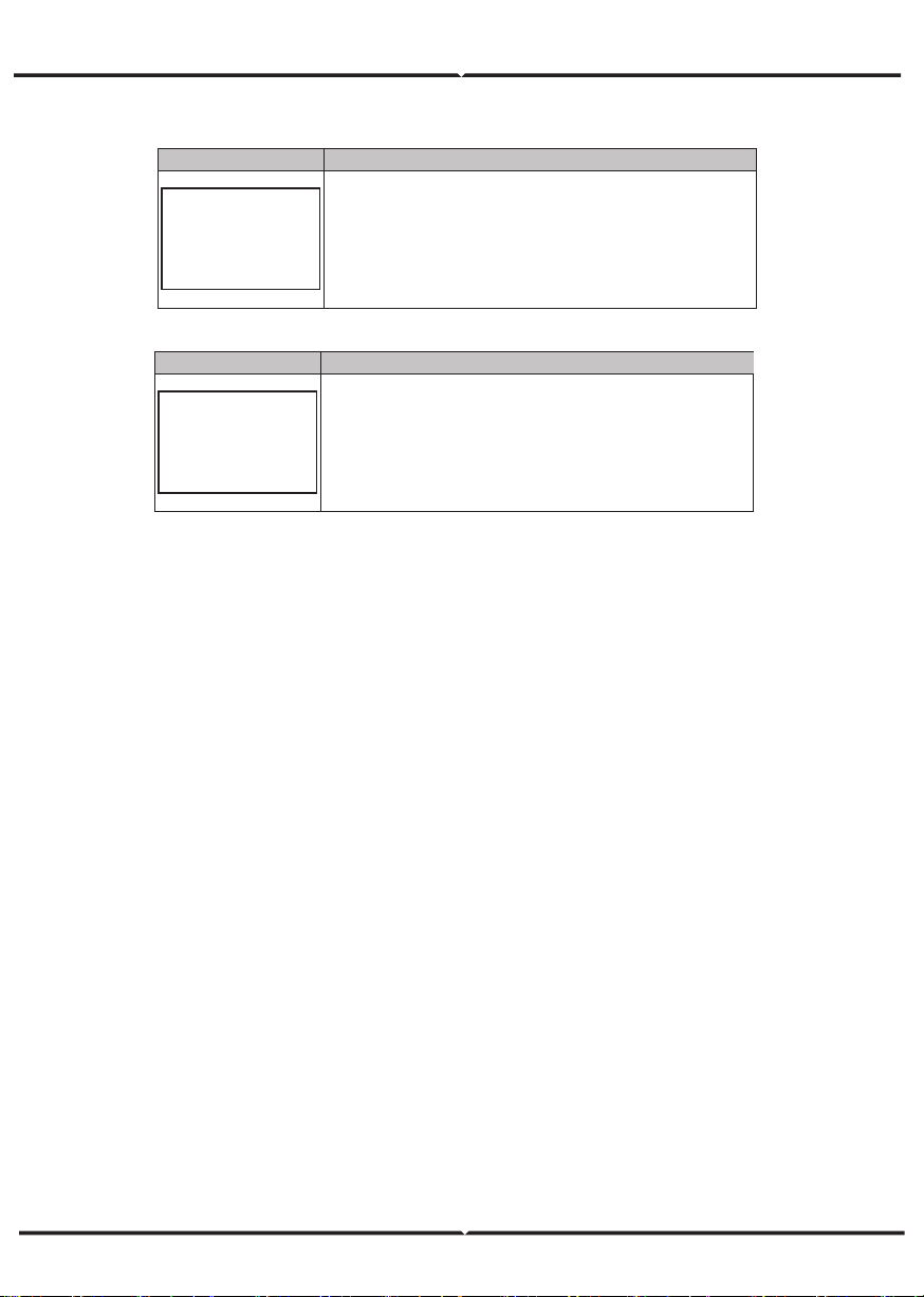
Interface Description
DC VOLTAGE
BUS: 384V
LeakCurr:
0mA
BUS: Real-time voltage of bus capacitor of the machine.
LeakCurr:
Real-time
leak current
of the machine.
Interface Description
BATTERY
VOLT: 300V
CURR:
10.00A
STA: C D F
Battery real-time voltage, current.
STA: Battery status. C: Charge. D: Discharge. F: Full charge.
Battery status depends on BMS instructions.
Interface Description
BATTERY INFO
TYPE: Lithium
TEMP: 26℃
SOC: 30%
TYPE: Battery type:(lead acid, lithium battery)
TEMP: Battery temperature.
SOC:
Percentage of battery surplus capacity
Interface Description
BMS PRMETER
CHAR VOL: 0.0V
CHARGE: 50A
DISCHA: 50A
CHAR VOL: Battery charging voltage.
CHARGE:
Battery charging current.
DISCHA:
Battery discharging current.
5.4.6 PV2 INPUT DISPLAY INTERFACE
5.4.7 DC VOLTAGE INTERFACE
5.4.8 B ATTERY INTERFACE
5.4.9 BATTERY CURRENT INTERFACE
5.4.10 BATTERY CURRENT INTERFACE
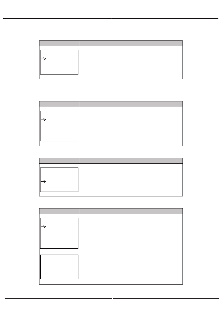
Interface Description
GRID
VOLT: 0.0V
CURR: 0.00A
FREQ: 0.00Hz
VOLT: Gird real-time voltage.
CURR: CT real-time current.
FREQ
: Grid real-time frequency.
Interface Description
INV
VOLT: 0.0V
CURR: 0.00A
FREQ: 0.00Hz
VOLT: INV real-time voltage.
CURR:
INV real-time current.
FREQ
: INV real-time frequency.
Interface Description
LOAD
VOLT: 0.0V
CURR: 0.00A
PERCENT: 0%
VOLT: LOAD real-time voltage.
CURR:
LOAD real-time current.
PERCENT
: LOAD real-time percentage.
Interface Description
POWER
INV: 0.0W
GRID: 0.0W
INV: INV power.
GRID:
Grid power.
Interface Description
POWER
PV I/P: 0W
LOAD: 0W
BAT: 0W
PV I/P: PV power.
LOAD:
LOAD power.
BAT: BAT power.
5.4.11 GRID-CONNECTED
5.4.12 INV
5.4.13 LOAD
5.4.14 POWER
5.4.15 POWER
Interface
Description
TEMPERATURE
INVER: 0℃
DCDC: 0℃
INSIDE: 0℃
INVER: INV Temperature.
DCDC:
DCDC Temperature.
INSIDE: Internal ambient temperature of the machine.
Interface
Description
STATE
SYS: STANDBY
INV: STANDBY
DCDC: STANDBY
System information: Display complete machine status
information, Including: Initialization, Standby, PV grid connection,
Grid connection of battery, Hybrid power supply, etc.
INV: Displays the inverter status information.
DCDC: Displays charging and discharging status information
5.4.16 TEMPERATURE
5.4.17 STATE
5.5.1 State
Interface
Description
USER
1:SETUP
2:INQUIRE
3:STATISTIC
SETUP: Press Enter to user settings interface.
INQUIRE:
Query machine model, serial number, software version.
STATISTIC
:
View machine run statistics.
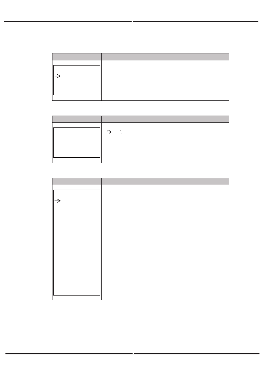
5.5.2 SET P ass word
Interface
Description
PASSWORD
INPUT: XXXXX
Enter the password required for setting. The default password
is
0000
Press the Up or Down keys to adjust the number, press the Enter
key to move the cursor forward, and press the Esc key move the
cursor backward.
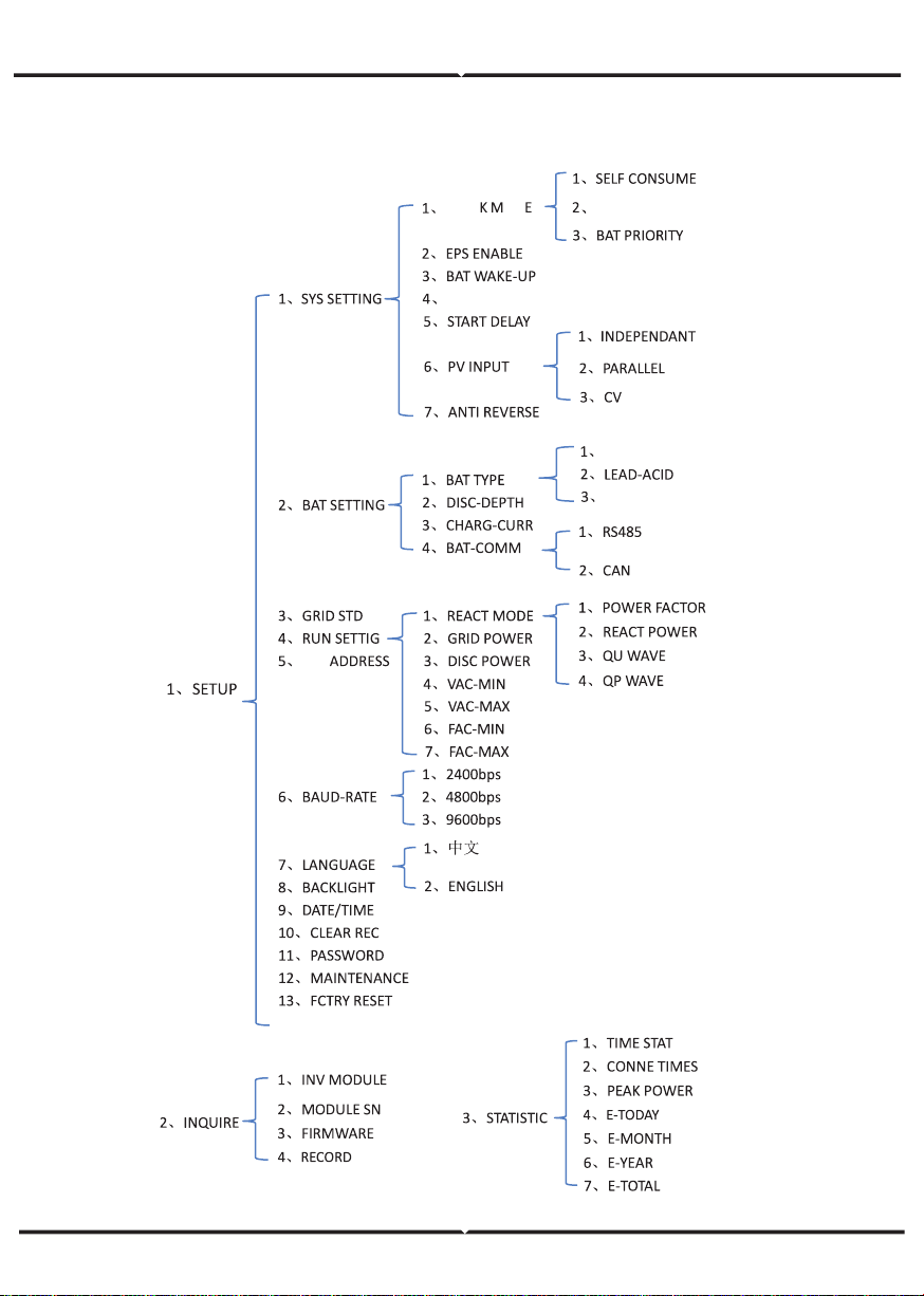
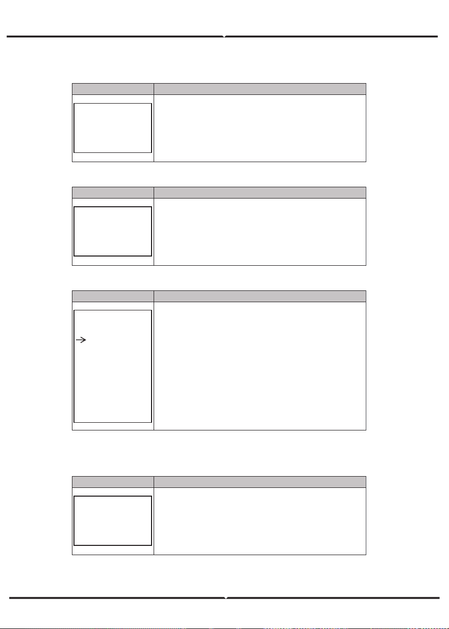
5.5.3 Setup
Interface
Description
SETUP
1:SYS SETTING
2:BAT SETTING
3:GRID STD
4:RUN SETTING
5:485 ADDRESS
6:BAUD RATE
7:LANGUAGE
8:BACKLIGHT
9:DATE/TIME
10:CLEAR REC
11:PASSWORD
12
:MAINTENANCE
13:FCTRY RESET
This interface is used for various information inquiry options.
Press the Up/Down button to make the corresponding selection.
Press Enter button to enter the selected menu.
Press ESC button return to the user interface.
There are 13 options in total.
SETTINGAS
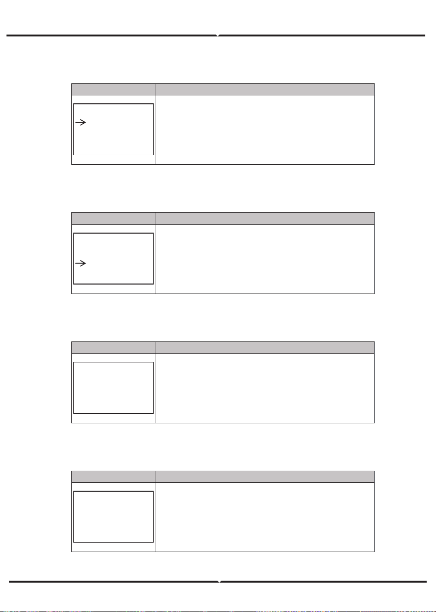
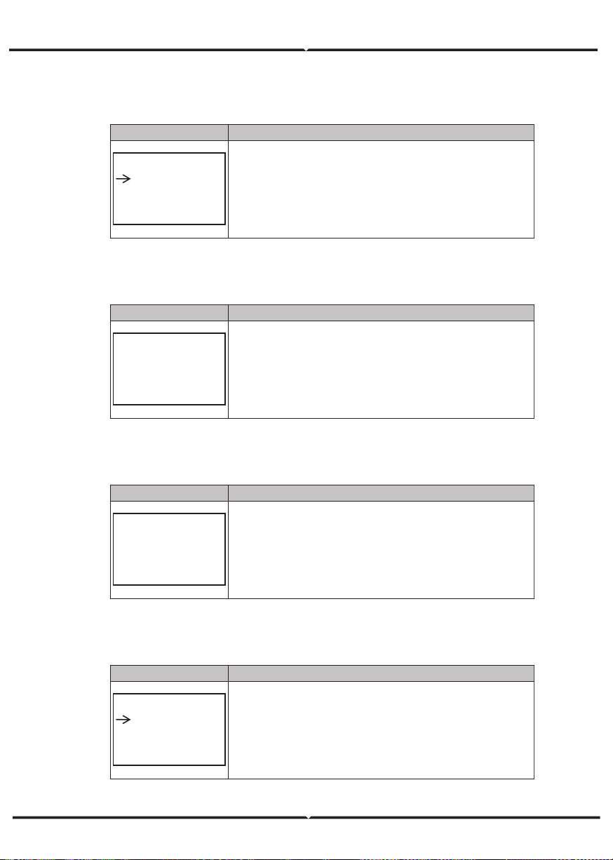
5.5.4.2 EPS en able
Interface
Description
EPS ENABLE
1:DISABLE
2:ENABLE
When the Grid and PV are powered off, Enable the battery to
supply power to the load, default option is enable.
5.5.4.3 Battery wak e- up
Interface
Description
WAKE-UP EN
1:DISABLE
2:ENABLE
When the battery is low and the battery relay has been
disconnected, the inverter will send instructions to the battery
forcibly sucking relay by BMS, and the inverter will charge.
The default option is disabled. (
Partial battery support)
5.5.4.4 REM OTE CT RL
Interface
Description
REMOTE CTRL
1:DISABLE
2:ENABLE
Remote control the inverter on or off.
(
Subsequent support…)
The default option is disabled.
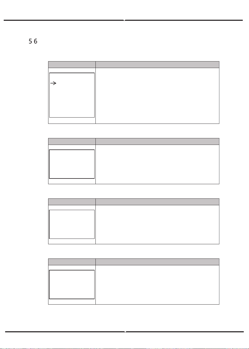
5.5.4.5 STAR T DEL AY
Interface
Description
START-UP DELAY
INPUT: 60
UNIT: SEC
The input value ranges from 20 to 300, which varies with different
standards.
5.5.4.6 PV I N PUT MO DE
Interface
Description
INPUT MODE
1.INDEPENDENT
2.PARALLEL
3.CV
Setup of PV Input mode.
The factory setting by default is Independent, When parallel input
is set to be stand-alone mode, PV power will be imbalanced.
5.5.4. 7 An ti Rev er se
Interface
Description
Anti Reverse
1.DISABLE
2.ENABLE
Anti Reverse
: Whether Inverter isn’t allowed to generate
electricity to the Grid.
The default option is disabled. It’s means inverter allowed to
generate electricity to the Grid
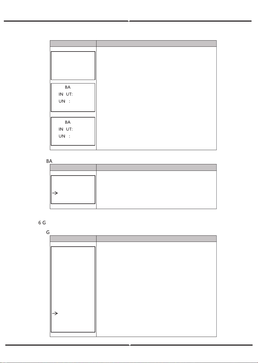
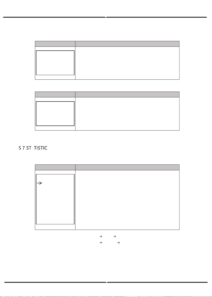
5.5.5 BA T SET TING
5.5.5.1 BA T SET TI NG
Interface
Description
BAT SETTING
1.BAT TYPE
2.DISC-DEPTH
3.CHARG-CURR
4.BAT-COMM
This interface is used to select battery parameters.
Press Up/Down button to move corresponding options;
Press Enter button to enter the selected menu;
Press ESC button to return to setting interface.
5.5.5.1.1 BA T T YPE
Interface
Description
BAT TYPE
1.DC-SOURCE
2.LEAD-ACID
3.Lithum
This interface is used to select battery type.
Press Up/Down button to move corresponding options;
Press Enter button to enter the selected menu.
Select the LEAD-ACID enter button to enter LEAD-ACID
interface;
5.5.5.1.1. 1 Lead -acid b att er y p aramet er
Interface
Description
LEAD-ACID
1.CHARG-VOLT
2.BAT END VOLT
3:BAT OVP
4:BAT CAP
CH A RGE VOLT
IN PUT: 13 5.0
UN IT: V
This interface is used to select LEAD-ACID battery
parameter.
Press Up/Down button to move corresponding options;
Press Enter button to enter the selected menu;
This interface is used to set the lead acid battery charging
voltage.
Interface
Description
BAT END VOLT
INPUT: 108.0
UNIT: V
T O VP
P 141 .0
IT V
T C A P
P 0450
IT A H
This interface is used to set the lead acid battery discharging
voltage.
This interface is used to set the lead acid battery
Charge
protection voltage.
This interface is used to set the lead acid Battery capacity.
5.5.5.2
T-COMM
Interface
Description
BAT-COMM
1.RS485
2.CAN
This interface is used to select battery communication.
Press Up/Down button to move corresponding options;
Press Enter button to enter the selected menu.
The default option is CAN.
5.5.
rid st andard
5.5.6.1
rid st d
Interface
Description
GRID STD
1.AU
2.AU-W
3.NZ
4.UK
5.VDE
6.KR
7.PHI
8.CN
9.US-CA
10.JP
11.CUSTOM
This interface is used to select Grid standard.
Press Up/Down button to move corresponding options;
Press Enter button to enter the selected menu.
1:AU--(Australia) 2:AU-W—(
)
3:NZ--
New Zealand 4:
UK--United Kingdom
5:VDE—Germany 6:KR—Korea
7:PHI—Philippines 8:CN—China
9:US-CA—America 10:JP—Japan
11:CUSTOM--User defined
Western Australia
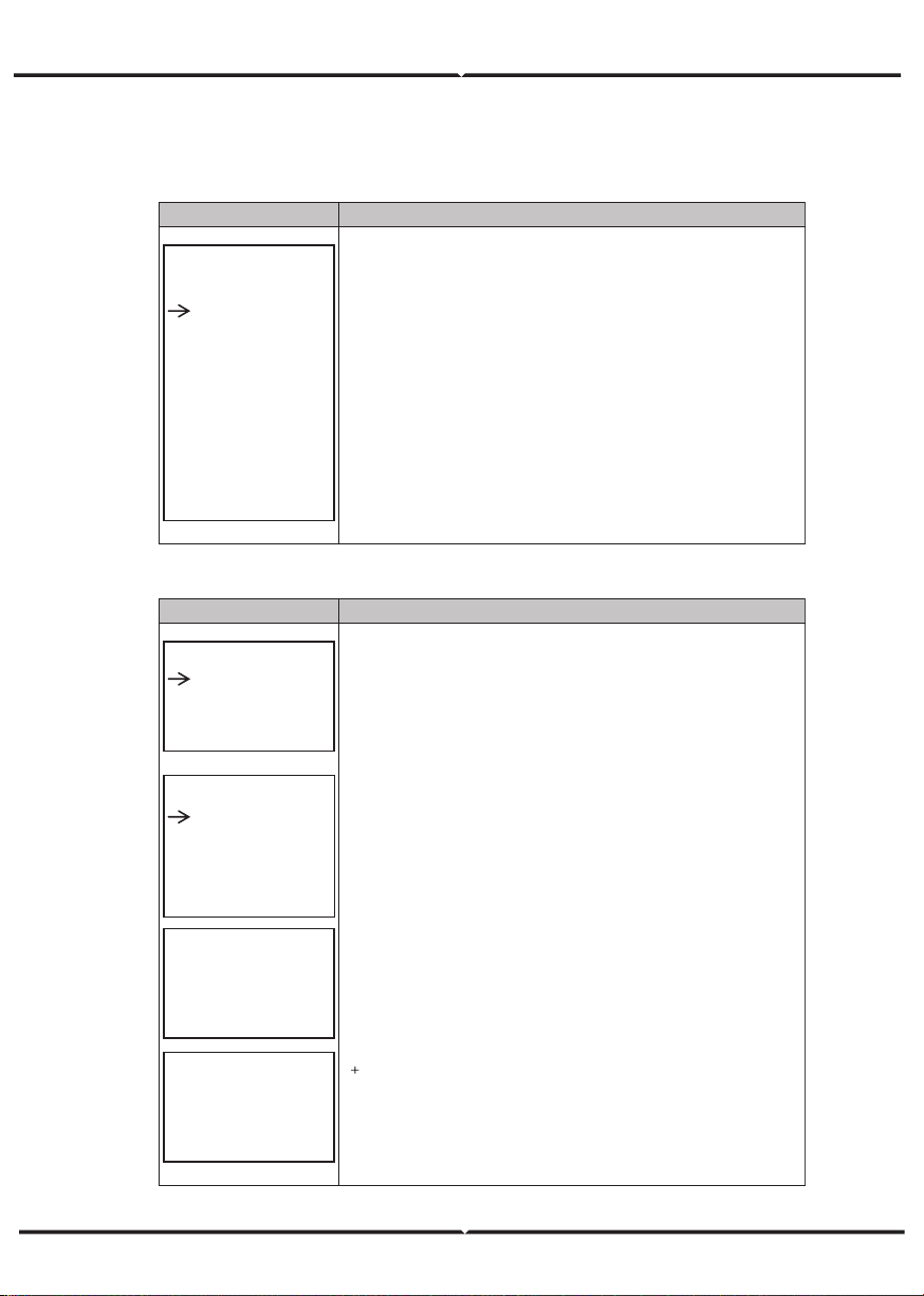
5.5.7 R UN SET TING
5.5.7. 1 RUN SET TING
Interface
Description
RUN SETTING
1.REACT MODE
2.GRID POWER
3.DISC POWER
4.PV POWER
5.VAC-MIN
6.VAC-MAX
7.FAC-MIN
8.FAC-MAX
9.ACTIVE REP.
This interface is used to select run setting.
Press Up/Down button to move corresponding options;
Press Enter button to enter the selected menu.
5.5.7. 2 RE ACT MODE
Interface
Description
RUN SETTING
1.REACT MODE
2.GRID POWER
3.DISC POWER
R EA CT MO D E
1.
PO W ER FACT OR
2.R EA CT P O WE R
3.Q U WAV E
4.Q P W AV E
POWER FACTOR
INPUT: C1.00
R EA CT PO WE R
IN PUT: + 00%
This interface is used to select react mode.
Press Up/Down button to move corresponding options;
Press Enter button to enter the selected menu.
The input value should range between L0.80 and L0.99 or
C0.8 and C1.00.
The input value should range between -60% and
60%, which varies with the standard.
5.5.7.3 G RID POWER
Interface
Description
GRID PERCENT
INPUT: 100%
The input value is power percent of grid.
5.5.7.4 DI SC HA RGE PO W ER
Interface
Description
DISC PERCENT
INPUT: 100%
The input value is power percent of battery discharge.
5.5.7.5 P V P OW ER
Interface
Description
PV PERCENT
INPUT: 100%
The input value is power percent of PV.
5.5.7.6 VAC - MI N
Interface
Description
GRID VOLT LOW
INPUT: 150
UNIT: V
The input value of Grid low voltage.
It effect when grid mode choose custom.
5.5.7.7 VAC-MA X
Interface
Description
GRID VOLT HIGH
INPUT: 280
UNIT: V
The input value of Grid high voltage.
It effect when grid mode choose custom.
5.5.7.8 FAC- MI N
Interface
Description
GRID FREQ LOW
INPUT: 57.0
UNIT: Hz
The input value of Grid low frequency.
It effect when grid mode choose custom.
5.5.7.9 FAC- M AX
Interface
Description
GRID FREQ HIGH
INPUT: 63.0
UNIT: Hz
The input value of Grid high frequency.
It effect when grid mode choose custom.
5.5.8.10 A CTI V E RE F.
Interface
Description
ACTIVE Type
1.PWR-VOLT RES
2.PWR-FREQ RES
3.PFC-VOLT RES
4.PFC-FREQ RES
5.Reserved1
6.Reserved2
7.Reserved3
8.Reserved4
This interface is used to select active reference.
Press Up/Down button to move corresponding options;
Press Enter button to enter the selected menu.
Each menu have enable or disable, set it when you need.
All default are enable.
5.5.8 485 Add res s
5.5.8.1 4 85 Add ress
Interface
Description
485 ADDRESS
INPUT: 1
This interface is used to select 485 address.
5.5.9 4 85 B AUD R ATE
5.5.9.1 BA UD R ATE
Interface
Description
SELECT
1.2400 bps
2.4800 bps
3.9600 bps
This interface is used to select 485 baud rate.
5.5.10 L ANG UAGE
5.5.10. 1 LANGU AGE
Interface
Description
LANGUAGE
1.Chinese
2.English
This interface is used to select language.
5.5.11 BA CKL IGHT
5.5.11. 1 B ACKLIG HT
Interface
Description
LIGHT TIME
INPUT: 20
UNIT: SEC
This interface is used to set light time.
5.5.12 D ATE /TIME
5.5.12. 1 D ATE/T IME
Interface
Description
DATE/TIME
DATE: 2021-12-25
TIME: 22:30:00
WEEK: Saturday
This interface is used to set date and time.
5.5.13 CLE AR R EC
5.5.13. 1 Clea r hi stor y
Interface
Description
DEL REC
1.CANCEL
2.CONFIRM
This interface is used to clear operation history.
5.5.14 P ASS W ORD
5.5.14. 1 PAS SW O RD
Interface
Description
PASSWORD
OLD: XXXXX
NEW: XXXXX
CONFIRM: XXXXX
This interface is used to set password.
5.5.15 M AI NTE NA NCE
5.5.15. 1 MA IN TENA N CE
Interface
Description
PASSWORD
INPUT: XXXXX
This interface is used to enter maintenance.
5.5.16 F CTR Y R ESET
5.5.16. 1 FACTOR Y R ESET
Interface
Description
FACTORY RESET
1.CANCEL
2.CONFIRM
This interface is used to reset the inverter.
. INQUIRE
5.6.1 I N
QUIRE
Interface
Description
INQUIRE
1.INV MODULE
2.MODULE SN
3.FIRMWARE
4.RECORD
5.DIAGNOSE
Press Up/Down button to move corresponding options;
Press Enter button to jump to the selected menu.
Press ESC button to return to other interface.
5.6.1.1 I N V MODULE
Interface
Description
MODEL
12K
This interface show inverter model..
5.6.2 MODULE SN
Interface
Description
S / N
GUID: XXXXXXXX
XXXXXXXXXXXXXX
SN:FXXXXXXXXXXX
This interface show module SN.
5.6.3 FIR M W ARE
Interface
Description
FIRMWARE
ARM: V1.XX.XX
DSP: V1.XX.XX
This interface show Software version.
5.6.4 R UN N IN G RE COR DS
Interface
Description
REC(01)
02:Batdisconnect
UP: 12-25 23:00
DOWN:
This interface show running recodes.
5.6.5 D IAG NOSE
Interface
Description
DIAGNOSE
000000 000000
000000 000000
000000 000000
Factory internal use.
. A
5.7.1 STATISTI C
Interface
Description
STAT.
1.TIME STAT.
2.CONNE.TIMES
3.PEAK POWER
4.E-TODAY
5.E-MONTH
6.E-YEAR
7.E-TOTAL
This interface show inverter operation statistic.
1.
Inverter operation
and
Grid-connection time statistic.
2.
Inverter
Grid-connection times statistic.
3.
Displays power peak in history and for the day.
4.
Displays statistic for the day (KWH).
5.
Displays statistic for the month (KWH).
6.
Displays statistic for the year (KWH).
7.
Displays statistic of the inverter (KWH).
N ote: 1. E- TOD AY/M ONTH/ YEAR/T OTAL INPUT PV/GRID (Consum e)/BA TD(Ba tter y discha rge)
OUT PUT BATC(Bat ter ychar ge)/GRI D (Gen eration )/
CNS UM (Lo ad con sume)
2. If the inv erter shu t down be fore 24:00 on tha t da y, and the da y statistic will not be stored.
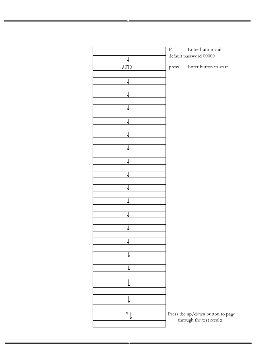
AUTOTEST FAST
14. TEST
the
Testing 59. S1...
Wait
Test 59.S1 OK!
Wait
Wait
Test ing 59.S2...
Wait
Testing 27.S1...
Wait
Test 27.S1 OK!
Wait
Testing 27.S2...
Wait
Test 27.S2 OK!
Wait
Testing 81>S1
Wait
Test 81>S1 OK!
Wait
Testing 81>S2...
Wait
Test 81>S2 OK!
Wait
Testing 81<S1...
Wait
Test 81<S1 OK!
Wait
Testing 81<S2...
Wait
Test 81<S2 OK!
Auto Test OK!
59.S1: 228V 902ms
Test 59.S2 OK!
Wait
59.S2: 229V 204ms
1. SETUP
ress the
27.S1: 228V 408ms
27.S2: 227V 205ms
81>.S1 49.9Hz 103ms
81>.S2 49.9Hz 107ms
81<.S1 50.0Hz 105ms
81<.S2 50.1Hz 107ms
Press the up/down button to page
through the test results
Press the up/down button to page
through the test results
Press the up/down button to page
through the test results
Press the up/down button to page
through the test results
Press the up/down button to page
through the test results
Press the up/down button to page
through the test results
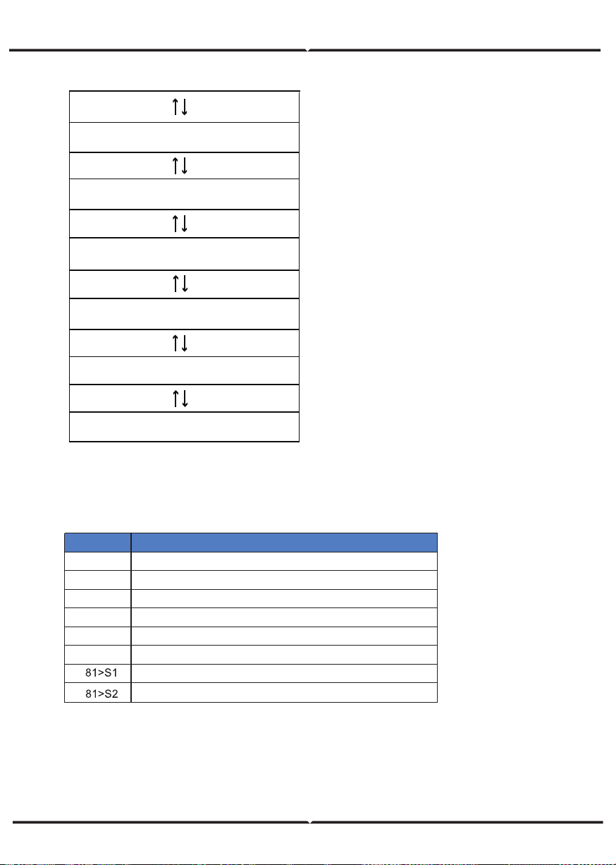
Under frequency protection
Object
27.S1
27.S2
59.S1
59.S2
81<S1
81<S2
Over voltage protection
Under voltage protection
Under voltage protection
Under frequency protection
Over frequency protection
Description
Over voltage protection
Over frequency protection

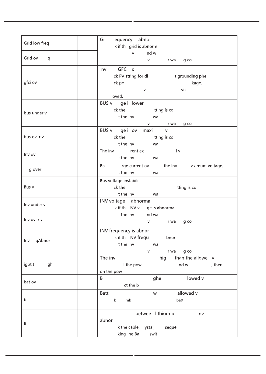
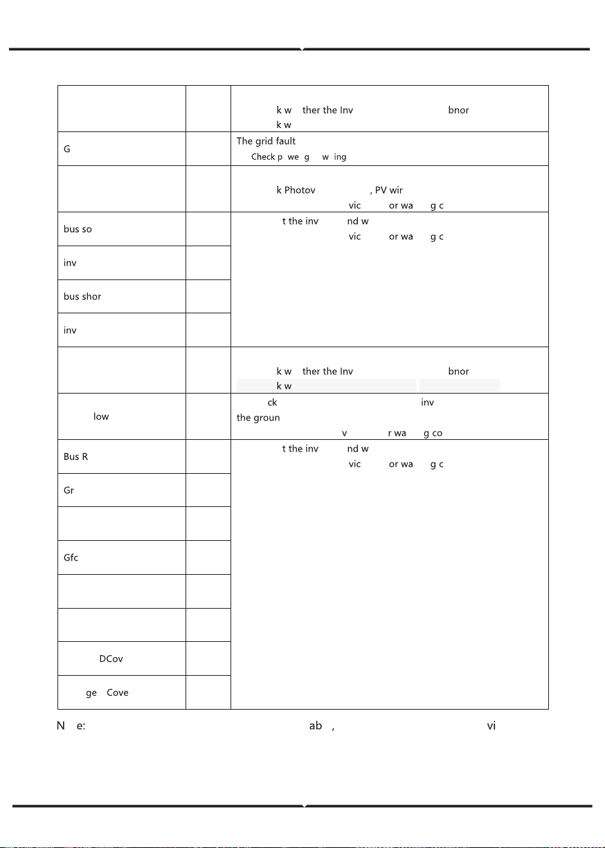
FAULT DIAGNOSIS AND SOLUTIONS
The inverter is easy to maintain. When you encounter the following problems, please
refer to the Solutions below, and contact the local distributor if the problem remains
unsolved. The following table lists some of the basic problems that may occur during
the actual operation as well as their corresponding basic solutions.
FAULT DIAGNOSIS TABLE
Co nten t
Di schg O verC ur
00
Batte ry disc harge over c urre nt.
(1) Not hi ng nee d to do, W ait o ne minute fo r t he inverte r t o rest ar t.
(2) Chec k w het her t he load is in c o mpl ia nce w ith t he s pec ificatio n.
(3) C ut o
ff
al l the powe r an d shut do wn al l the mac hin es ; disc onn ect
the load and plu g in to res tart m ac hines, t he n c heck
O ver Load
01
The l oad p owe r i s grea ter t han other powe r(PV,B AT ).
(1) Chec k w het her t he load is in c o mpl ia nce w ith t he maxim um
po wer of t he machi ne.
(2) Cut off all the powe r and shut do wn all the machi nes; disc onnect
the load and plu g in to res tart m ac hines, t he n c heck whether t he
load is s ho rt c ircuited if t he f au lt ha s be en e limin at ed.
(3) Co ntact c us tome r s ervic e if e rror warnin g co ntinues.
BatDi sc onnect
02
Batte ry Di sconne ct. (Batte ry volt age no t i den tified)
(1) Chec k w het her t he ba tte ry is c onnec ted.
(2) Chec k if b att er y w iring port i s o pe n c ircuited.
(3) Co ntact c us tome r s ervic e if e rror warnin g co ntinues.
Ba t Under V ol
03
Batte ry voltage low t hat no rm al ra nge .
(1) Chec king Syste m Settings , I f s o, pow er o
ff
an d rest ar t.
(2) Chec k if t he gr id p ow er do wn. I f so, wait ting fo r t he g rid pow er
up, t he inverter will au tom atic ally c ha rg e.
(3) Co ntact c us tome r s ervic e if e rror warnin g co ntinues.
Bat L ow c apacity
04
Batt er y Low that setting c ap ac ity.(SO C< 100% - DOD )
Ba t Ov er V ol
05
The b att ery v oltage is grea ter th an the Inv er ter m aximu m v olta ge .
(1) Chec king Sys te m Settings , If s o , pow er o
ff
an d rest ar t.
(2)
C o ntact c ust o m er s ervice if e rror warnin g co ntinues.
Gird low vol
06
Gr id v oltage is ab nor mal
(1)Chec k if th e grid is abnor ma l.
(2) R esta rt the inv er ter a nd wait until it f un ctions norma lly.
(3) Conta ct c ust omer se rvice if erro r wa rnin g co ntin ue s.
Gr id ov er v ol
07
Co des
Solutions
08
id Fr is ma l.
(1)Chec
e al.
(2) R esta rt the in
erter a ait u ntil it f unctions nor m ally .
(3) Conta ct c ust omer se r
ice if erro rnin ntin ues.
erFr e
09
er
10
I er ter I e cee ds sta ndar d.
(1) Ch e
rect or in direc nomenon.
(2) Ch e
riphe rals o f m achin e for curr ent le a
(3) Conta ct the loc al in
erter cust omer se r e if fa ult r em ains
unre m
ol
13
olta s than norma l.
(1) Ch e
in put m ode se rrect.
(2) R esta r
er ter a nd it until it f un ctions nor m ally .
(3) Conta ct c ust omer se r
ice if erro rnin ntin ues.
e ol
14
olta s er mum alue..
(1) Ch e in put m ode se rrect.
(2) R esta r
er ter a nd it until it f un ctions norma lly.
er c ur
15
er ter cur cee ds th e n or ma alue .
(1) R esta r
er ter a nd it until it f un ctions norma lly.
Ch cur
16
tter y cha er th an er ter m
(1) R esta r
er ter a nd it until it f un ctions norma lly.
ol os c
17
ty.
(1) Ch e
in put and out put mode se rrec t.
(2) R esta r
er ter a nd it until it f un ctions norma lly.
ol
18
is
(1)Chec e I olta i l.
(2) R esta r
er ter a it until it f unctio ns n or ma lly.
(3) Conta ct c ust omer se r
ice if erro rnin ntin ues.
e ol
19
Fre
20
mal
(1)Chec e I en cy is a ma l.
(2) R esta r
er ter a nd it until it f un ctions nor ma lly.
(3) Conta ct c ust omer se r
ice if erro rnin ntin ues.
emp h
21
er ter t em pera tur e is her d alue
(1) Cu t o ff a er o f t he m achine a ait one ho ur turn
er of the ma chin e.
er t emp
23
att er y temp erature is hi r than the al al ue.
(1) Disco nn e
att ery a nd rec onne ct it a fter a n hou r.
at Un de rTemp
24
er y temp eratur e is lo than the alue.
(1) C hec
the a ient t empe rat ure nea r the ery t o s ee i f it meets the
spec if icati ons.
MS co mm.fa il
27
Com munication n att er y and i er ter is
mal.
(1) Ch ec cr Line nce.
(2) Ch ec
t tter y ch.
Fan fa il
28
Fan fa il
(1) Ch ec
he er ter t emper atur e is a mal.
(2)
rid Pha se e rr
30
pha se.
(1)
o r rid ir
Arc F ault
31
PV Arc F ault
(1) Ch ec
olta ic p anels e.
(2) Conta ct cust omer se r
e if err rnin ontin ue s.
ft fa il
32
(1) R estar erter a ait u ntil it fu nc tions norma lly.
(2) Conta ct cust omer se r
e if err rnin ontin ue s.
so ft fa il
33
t
34
shor t
35
fan fault
36
Fan fa ult.
(1) Ch ec
he er ter t emper atur e is a mal.
PV iso
37
(1) Ch e if the PE line is con ne cted to the erter and is conn ected to
d.
(2)Conta ct cust o mer se r
ice if erro rnin ntin ue s.
elay F ault
38
(1) R estar erter a ait u ntil it fu nc tions norma lly.
(2) Conta ct cust omer se r
e if err rnin ontin ue s.
id R elay F ault
39
EPS rly fa ult
40
i fa ult
41
Selftest fa il
44
System f au lt
45
Cu rrent er
46
Volta D r
47
ot
If an er ror oc cur s that is no t li sted i n t he t le
Please
Co ntac t c us tom er ser ce .
Ch ec
he ther the fans run pr operly .(If you can see it)
(2)
Ch ec
he ther the fans run pr operly .(If you can see it)