
HDG3000B(C) Series
Functions and Arbitrary Waveform
Generator
User Manual
(V1.0.1)

Content
Copyright Declaration .......................................................................................................... 1
Summary of general safety matters..................................................................................... 2
General Safety Summary ............................................................................................. 2
Safety Terms and Symbols ........................................................................................... 3
Product Scrapping ........................................................................................................ 3
Brief Introduction .................................................................................................................. 4
Chapter 1 Quick Start .......................................................................................................... 6
1.1 General Inspection ................................................................................................. 7
1.2 Front Panel ............................................................................................................. 7
1.3 Rear Panel .............................................................................................................. 9
1.4 Prepare Instrument for Use .................................................................................. 11
1.5 The User Interface ................................................................................................ 12
1.6 Parameter Setting Method ................................................................................... 13
1.6.1 Numeric Keypad ......................................................................................... 13
1.6.2 Direction Keys and Knob ........................................................................... 13
1.7 Help ...................................................................................................................... 14
Chapter 2 Basic Waveform Output .................................................................................... 15
2.1 Select the Channel ............................................................................................... 16
2.2 Set the Parameter ................................................................................................ 16
2.2.1 Select the Basic Waveform ........................................................................ 16
2.2.2 Set the Frequency ...................................................................................... 16
2.2.3 Set the Amplitude ....................................................................................... 17
2.2.4 Set the DC Offset Voltage .......................................................................... 17
2.2.5 Set the Start Phase .................................................................................... 18
2.2.6 Set the Duty Cycle ..................................................................................... 19
2.2.7 Set the Symmetry ....................................................................................... 19
2.2.8 Set the Pulse Parameters .......................................................................... 20
2.2.9 Enable the Channel Output ........................................................................ 21
2.3 Basic Waveform Output Example ........................................................................ 22
Chapter 3 Arbitrary Waveform Output ............................................................................... 24
3.1 Enable Arbitrary Waveform .................................................................................. 25
3.2 Select Arbitrary Waveform .................................................................................... 25
Chapter 4 Harmonic Output ............................................................................................... 30
4.1 Overview ............................................................................................................... 31
4.2 Set the Basic Waveform Parameters ................................................................... 31
4.3 Set the Harmonic Order ....................................................................................... 31
4.4 Set the Harmonic Type ......................................................................................... 32
4.5 Set the Harmonic Amplitude ................................................................................. 32
4.6 Set the Harmonic Phase ...................................................................................... 32
Chapter 5 Modulation ........................................................................................................ 33
5.1 AM Modulation ...................................................................................................... 34
I

5.1.1 Select AM Modulation ................................................................................ 34
5.1.2 Carrier Waveform Shape ........................................................................... 34
5.1.3 Carrier Waveform Frequency ..................................................................... 34
5.1.4 Modulation Source ..................................................................................... 34
5.1.5 Modulation Frequency ............................................................................... 35
5.1.6 Modulation Depth ....................................................................................... 35
5.2 DSB-AM Modulation ............................................................................................. 35
5.2.1 Select DSB-AM Modulation ....................................................................... 36
5.2.2 Carrier Waveform Shape ........................................................................... 36
5.2.3 Carrier Waveform Frequency ..................................................................... 36
5.2.4 Modulation Source ..................................................................................... 36
5.2.5 Modulation Frequency ............................................................................... 37
5.2.6 Modulation Depth ....................................................................................... 37
5.3 FM Modulation ...................................................................................................... 37
5.3.1 Select FM Modulation ................................................................................ 38
5.3.2 Carrier Waveform Shape ........................................................................... 38
5.3.3 Carrier Waveform Frequency ..................................................................... 38
5.3.4 Modulation Source ..................................................................................... 38
5.3.5 Modulation Frequency ............................................................................... 39
5.3.6 Frequency Deviation .................................................................................. 39
5.4 PM Modulation ...................................................................................................... 39
5.4.1 Select PM Modulation ................................................................................ 40
5.4.2 Carrier Waveform Shape ........................................................................... 40
5.4.3 Carrier Waveform Frequency ..................................................................... 40
5.4.4 Modulation Source ..................................................................................... 40
5.4.5 Modulation Frequency ............................................................................... 41
5.4.6 Phase Deviation ......................................................................................... 41
5.5 ASK Modulation .................................................................................................... 41
5.5.1 Select ASK modulation .............................................................................. 41
5.5.2 Carrier Waveform Shape ........................................................................... 42
5.5.3 Carrier Waveform Amplitude ...................................................................... 42
5.5.4 Modulation Source ..................................................................................... 42
5.5.5 ASK Rate .................................................................................................... 42
5.5.6 Modulation Amplitude ................................................................................. 43
5.6 FSK Modulation .................................................................................................... 43
5.6.1 Select FSK Modulation .............................................................................. 43
5.6.2 Carrier Waveform Shape ........................................................................... 43
5.6.3 Carrier Waveform Frequency ..................................................................... 43
5.6.4 Modulation Source ..................................................................................... 43
5.6.5 FSK Rate .................................................................................................... 44
5.6.6 Hopping Frequency .................................................................................... 44
5.7 PSK Modulation .................................................................................................... 44
5.7.1 Select PSK Modulation .............................................................................. 44
5.7.2 Carrier Waveform Shape ........................................................................... 45
II

5.7.3 Carrier Waveform Phase ............................................................................ 45
5.7.4 Modulation Source ..................................................................................... 45
5.7.5 PSK Rate .................................................................................................... 45
5.7.6 Modulation Phase ...................................................................................... 45
5.8 BPSK Modulation ................................................................................................. 46
5.8.1 Select BPSK Modulation ............................................................................ 46
5.8.2 Carrier Waveform Shape ........................................................................... 46
5.8.3 Carrier Waveform Phase ............................................................................ 46
5.8.4 Modulation Source ..................................................................................... 46
5.8.5 BPSK Rate ................................................................................................. 46
5.8.6 Modulation Phase ...................................................................................... 47
5.9 QPSK Modulation ................................................................................................. 47
5.9.1 Select QPSK Modulation ........................................................................... 47
5.9.2 Carrier Waveform Shape ........................................................................... 47
5.9.3 Carrier Waveform Phase ............................................................................ 47
5.9.4 Modulation Source ..................................................................................... 47
5.9.5 QPSK Rate ................................................................................................. 48
5.9.6 Modulation Phase ...................................................................................... 48
5.10 3FSK Modulation ................................................................................................ 48
5.10.1 Select 3FSK Modulation .......................................................................... 48
5.10.2 Carrier Waveform Shape ......................................................................... 48
5.10.3 Carrier Waveform Frequency ................................................................... 48
5.10.4 Modulation Source ................................................................................... 49
5.10.5 3FSK Rate ................................................................................................ 49
5.10.6 Hopping Frequency .................................................................................. 49
5.11 4FSK Modulation ................................................................................................ 49
5.11.1 Select 4FSK Modulation ........................................................................... 49
5.11.2 Carrier Waveform Shape .......................................................................... 49
5.11.3 Carrier Waveform Frequency ................................................................... 50
5.11.4 Modulation Source ................................................................................... 50
5.11.5 4FSK Rate ................................................................................................ 50
5.11.6 Hopping Frequency .................................................................................. 50
5.12 OSK Modulation ................................................................................................. 50
5.12.1 Select OSK Modulation ............................................................................ 51
5.12.2 Carrier Waveform Shape ......................................................................... 51
5.12.3 Carrier Waveform Frequency ................................................................... 51
5.12.4 Modulation Source ................................................................................... 51
5.12.5 OSK Rate ................................................................................................. 52
5.12.6 Oscillate Time ........................................................................................... 52
5.13 PWM Modulation ................................................................................................ 52
5.13.1 Select PWM Modulation ........................................................................... 52
5.13.2 Carrier Waveform Shape ......................................................................... 52
5.13.3 Carrier Waveform Duty ............................................................................ 53
5.13.4 Modulation Source ................................................................................... 53
III

5.13.5 Modulation Frequency ............................................................................. 53
5.13.6 Duty Deviation .......................................................................................... 54
Chapter 6 Sweep ............................................................................................................... 55
6.1 Select Sweep ........................................................................................................ 56
6.2 Start Frequency and Stop Frequency................................................................... 56
6.3 Center Frequency and Frequency Span .............................................................. 56
6.4 Linear Sweep ........................................................................................................ 57
6.5 Sweep Time .......................................................................................................... 57
6.6 Return Time .......................................................................................................... 57
6.7 Hold Time ............................................................................................................. 58
6.8 Mark Frequency .................................................................................................... 58
6.9 Sweep Trigger Source .......................................................................................... 58
6.10 Trigger Output Edge ........................................................................................... 58
Chapter 7 Burst .................................................................................................................. 60
7.1 Select Burst .......................................................................................................... 61
7.2 Burst Type............................................................................................................. 61
7.3 Burst Count ........................................................................................................... 63
7.4 Burst Period .......................................................................................................... 63
7.5 Burst Phase .......................................................................................................... 63
7.6 Trigger Source ...................................................................................................... 63
7.7 Gate Polarity ......................................................................................................... 64
7.8 Trigger Output Edge ............................................................................................. 64
Chapter 8 Counter ............................................................................................................. 65
Chapter 9 Store .................................................................................................................. 66
9.1 Store System ........................................................................................................ 66
9.2 File Operation ....................................................................................................... 66
Chapter 10 Utility ............................................................................................................... 69
10.1 Sync .................................................................................................................... 70
10.2 Impedance Settings ............................................................................................ 71
10.3 System Settings.................................................................................................. 72
10.3.1 Language ................................................................................................. 72
10.3.2 Clock Source ............................................................................................ 72
10.3.3 Power On Settings ................................................................................... 73
10.3.4 Intensity .................................................................................................... 73
10.3.5 System Information .................................................................................. 73
10.3.6 Unit ........................................................................................................... 73
10.3.7 Save Picture ............................................................................................. 73
10.4 Firmware Update ................................................................................................ 74
Chapter 11 Remote Control ............................................................................................... 75
11.1 Install Keysight IO libraries suite ........................................................................ 76
11.2 Remote Control via USB .................................................................................... 80
Appendix A Specifications .................................................................................................. 82
Appendix B Accessories .................................................................................................... 89
IV

Copyright Declaration
All rights reserved; no part of this document may be reproduced or transmitted in any form or by
any means, electronic or mechanical, without prior written permission from Hantek Technologies
Co., Ltd (hereinafter referred to as ‘Hantek’).
Hantek reserves all rights to modify this document without prior notice. Please contact Hantek for
the latest version of this document before placing an order.
Hantek has made every effort to ensure the accuracy of this document but does not guarantee the
absence of errors. Moreover, Hantek assumes no responsibility in obtaining permission and
authorization of any third-party patent, copyright or product involved in relation to the use of this
document.
User Manual1

Summary of general safety matters
General Safety Summary
Read the following safety precautions to avoid injury and prevent damage to this product or any
products connected to it. To evade potential hazards, use this product only as specified.
Only qualified personnel should perform maintenance.
Avoid fire or personal injury.
Use suitable power cord. Use only the power cord specified for this product and certified for the
country of use.
Connect and disconnect properly. Connect a probe with the oscilloscope before it is connected
to measured circuits; disconnect the probe from the oscilloscope after it is disconnected from
measured circuits.
Ground the product. This product is grounded through the grounding conductor of the power
cord. To avoid electric shock, the grounding conductor must be connected to earth ground. Before
making connections to the input or output terminals of the product, ensure that the product is
properly grounded.
Connect the probe in a right way. The probe ground lead is at ground potential. Do not connect
the ground lead to an elevated voltage.
Check all terminal ratings. To avoid fire or shock hazard, check all ratings and markings on the
product. Refer to the product manual for detailed information about ratings before making
connections to the product.
Do not operate without covers. Do not operate this product with covers or panels removed.
Avoid exposed circuitry. Do not touch exposed connections and components when power is
present.
Do not operate with suspected failures. If you suspect there is damage to this product, have it
inspected by qualified service personnel.
Assure good ventilation.
Do not operate in wet/damp environments.
Do not operate in an explosive atmosphere.
Keep product surfaces clean and dry.
User Manual 2

Safety Terms and Symbols
Terms on the product. The following terms may appear on the product:
Danger
It represents that harms may be caused to you at once if
you perform the operation.
Warning It represents that latent harms may be caused to you if
you perform the operation.
Notice
It represents the damage possibly caused to the product
or other properties if you perform the operation.
Characters on the product. The following characters may appear on the product:
Product Scrapping
Device Recycling
We need extract and utilize natural resources to produce this device. If you do not reclaim the
device in a proper way, some substances it contains may become harmful or poisonous to
environments or human bodies. To avoid them being released outside and to minimize the waste
of natural resources, we suggest you reasonably call back this device to ensure proper recovery
and recycling of most materials within it.
Notice
Please read
the manual
Protective
ground terminal
Measuring
ground terminal
Chassis
ground terminal
User Manual 3

Brief Introduction
HDG3000 series waveform generator is an economical, high performance, multi-functional dual
channel function/arbitrary waveform generator that does integrates functions of function generator,
arbitrary waveform generator, pulse generator, harmonic generator, analog/digital modulator,
counter, etc.
Features:
The six maximum output frequencies are 100MHz, 80MHz, 60MHz, 40MHz, 25MHz and
15MHz.
16-bit vertical resolution, 300MSa/s sampling rate for CH1 and CH2.
2 Mpts Max. arbitrary waveform Memory Depth.
Precisely adjust the phases of the two channels
160 waveforms or functions: Sine, Square, Ramp, Pulse, Noise, Exponential Rise,
Exponential Fall, ECG, Gauss, Haversine, Lorentz, Dual Tones, Harmonics, Video Signal,
Radar Signal, DC etc.
Rise Time and Fall Time of the Pulse could be adjusted separately
Enable to output harmonic with specified order and amplitude, enable to output up to 16th
order of harmonic.
Various modulation types: AM, DSB-AM, FM, PM, ASK, FSK, PSK, BPSK, QPSK, 3FSK,
4FSK, OSK and PWM modulations.
Support frequency sweep and Burst output
Dual channels can perform internal /external /another channel modulation and
internal/external/manual trigger separately or at the same time.
Dual channels can output sync signal separately or at the same time
Provide 80MHz Counter; enable to measure various parameters of external signal such as
frequency, period, duty cycle, positive pulse width and negative pulse width.
Support waveform copy and state copy between channels.
Enable store and read instrument state file, and enable read arbitrary waveform data file from
external storage device.
Standard configuration interface: Front USB Host and RearUSB Device.
Abundant I/O: waveform output, sync signal output, modulation input, 10MHz clock
input/output and trigger input/output.
Support FAT32 formated USB storage device (flash type) storage
Provide Chinese and English help information, prompt message and interface display.
Equipped with powerful waveform editing PC software
Compatible with SCPI (Standard Command for Programmable Instruments).
4.3-inch color TFT LCD screen.
User Manual 4

Model
Model Channels Max.Frequency
CH1/CH2
Sampling Rate
CH3
Sampling Rate
HDG3012B 2 15MHz 300MS/s -
HDG3022B 2 25MHz 300MS/s -
HDG3042B 2 40MHz 300MS/s -
HDG3062B 2 60MHz 300MS/s -
HDG3082B 2 80MHz 300MS/s -
HDG3102B 2 100MHz 300MS/s -
HDG3013C 3 15MHz 300MS/s 150MSa/s
HDG3023C 3 25MHz 300MS/s 150MSa/s
HDG3043C 3 40MHz 300MS/s 150MSa/s
HDG3063C 3 60MHz 300MS/s 150MSa/s
HDG3083C 3 80MHz 300MS/s 150MSa/s
HDG3083C 3 100MHz 300MS/s 150MSa/s
Format Conventions in this Manual
Keys
The keys on the front panel are usually denoted by the format of "Key Name (Bold) + Square
Brackets (Bold)". For example, [Utility].
User Manual 5

Chapter 1 Quick Start
This chapter introduces the front panel, rear panel, user interface and parameter setting method
as well as precautions when using the instrument for the first time.
General Inspection
Front Panel
Rear Panel
Prepare Instrument for Use
The User Interface
Parameter Setting Method
Help
User Manual 6
1.1 General Inspection
Please check the instrument as following steps after receiving an oscilloscope:
Check the shipping container for damage:
Keep the damaged shipping container or cushioning material until the contents of the
shipment have been checked for completeness and the instrument has been checked
mechanically and electrically.
Check the accessories:
Accessories supplied with the instrument are listed in "Accessories" in this manual. If the
contents are incomplete or damaged, please notify the franchiser.
Check the instrument:
In case there is any mechanical damage or defect, or the instrument does not operate properly or
fails performance tests, please notify the franchiser.
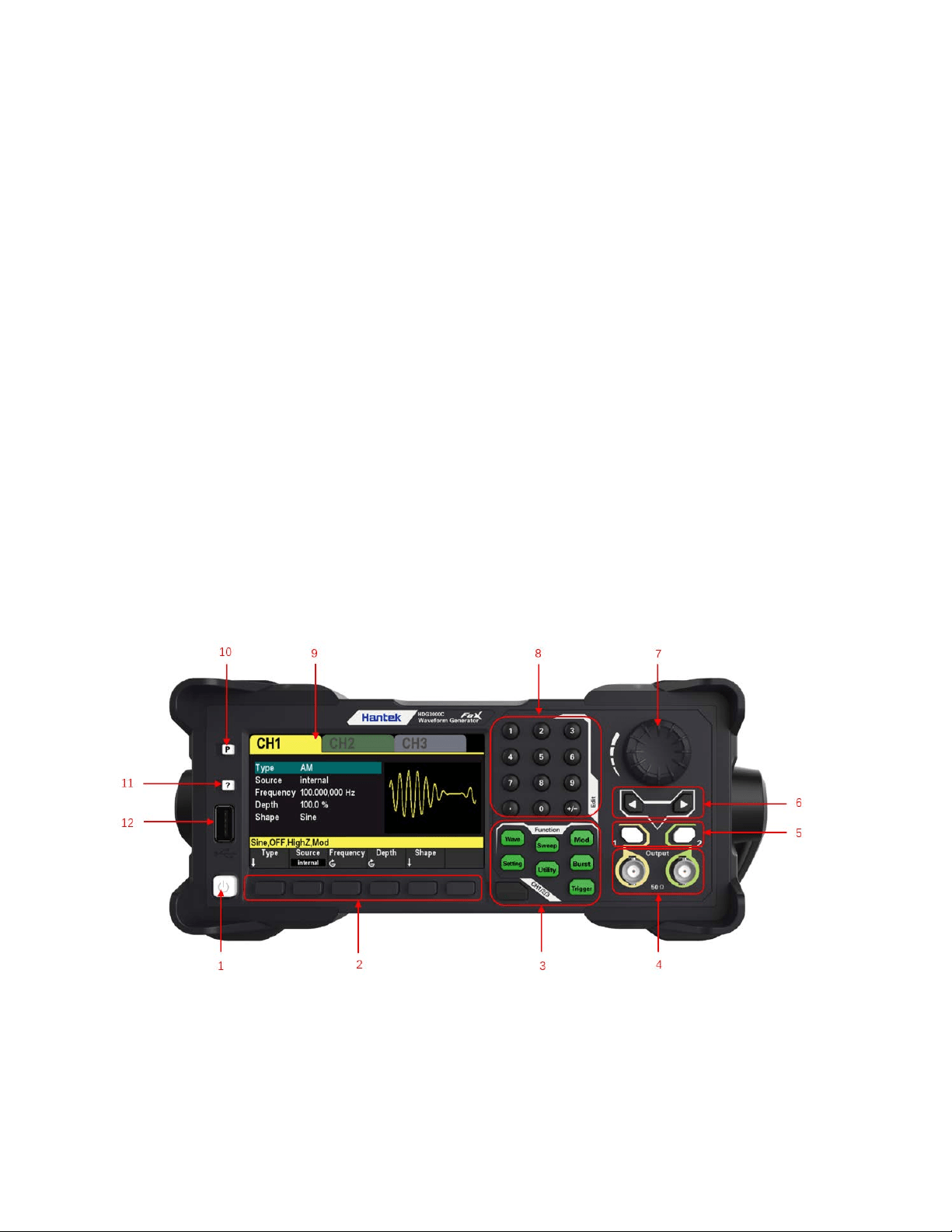
1.2 Front Panel
The content below simply describes and introduces the front panel of HDG3000B(C) so that you
can get familiar with it well within the shortest time.
1. On/Off Switch
2. Menu Softkey
Correspond to the left menus respectively. Press any softkey to activate the corresponding
menu.
3. Function Keys
Wave: Select the waveform that the current channel will output.
Setting: Set the parameters of the waveform that the current channel will output.
Utility: Auxiliary functions and system Settings.Used to set auxiliary function and system
User Manual 7

parameters.
Mod: Enablegenerate modulated waveforms.A variety of analog and digital modulation
methods are provided to generate AM, DSB-AM, FM, PM, ASK, FSK, PSK, BPSK, QPSK,
3FSK, 4FSK, OSK and PWM modulation signals.
Sweep: Enable generate sweep signals of "sine", "square", "ramp", "pulse", "harmonic" and
"arbitrary (except DC)".
Burst: Enablegenerateburst signals of "sine", "square", "ramp", "pulse", "harmonic" and
"arbitrary (except DC)".
Trigger: Manually triggered button.In sweep or burst mode, used to manually trigger CH1 or
CH2 to produce a sweep or burst signal (only when 1Output or 2Output is turned on).
CH1/2/3 or CH1/2: Channel switching.Press this button to switch menu setting channel.
After selectingCH1, users can set the waveforms, parameters, and configuration of CH1.
After selecting CH2, users can set the waveforms, parameters, and configuration of CH2.
After selecting CH3, users can set the waveform, parameters, and configuration of
CH3.Only HDG3000C supports CH3 output.
4. CH1/CH2 Output Connector
BNC connector with 50Ω nominal output impedance.
When 1Output or 2Outputis enabled (the backlight turns on), this connector output waveform
according to the current configuration of the channel.
5. Channel ON/OFF: Enable or disable the output of CH1 or CH2.
6. Direction Keys
When using the knob and direction keys to set parameters, the direction keys are used to
switch the digits of the parameter.
During file name input, they are used to move the cursor.
7. Knob
During parameter setting, it is used to increase (clockwise) or decrease (counterclockwise)
the current highlighted number. It is used to select file storage location or select the file to be
recalled when storing or recalling file. It is used to switch the character in the soft keyboard
when entering filename.
8. NumetricKeypad
It is used to input parameters and consists of numbers (0 to 9), decimal point (.), operators
(+/-).Note that if a negative is required, please input an operator "-" before the numbers. (For
the use method of the numeric keypad, refer to the introduction in "
Parameter Setting
Method").
9. LCD
4.3-inch color TFT LCD screen, display the current function menu and parameter settings,
system stateas well as prompt messages.
10. Default
It is used to restore the instrument state to the factory default settings.
11. Help
To get the context help information about any front-panel key or menu softkey, press this key
User Manual 8
and then press the button you need to get the help information for.
12. USB HOST Interface
External storage device (USB disk) can be accessed for saving or loading settings files.The
file system format of the external storage device is FAT32 and the memory is no more than
32G.
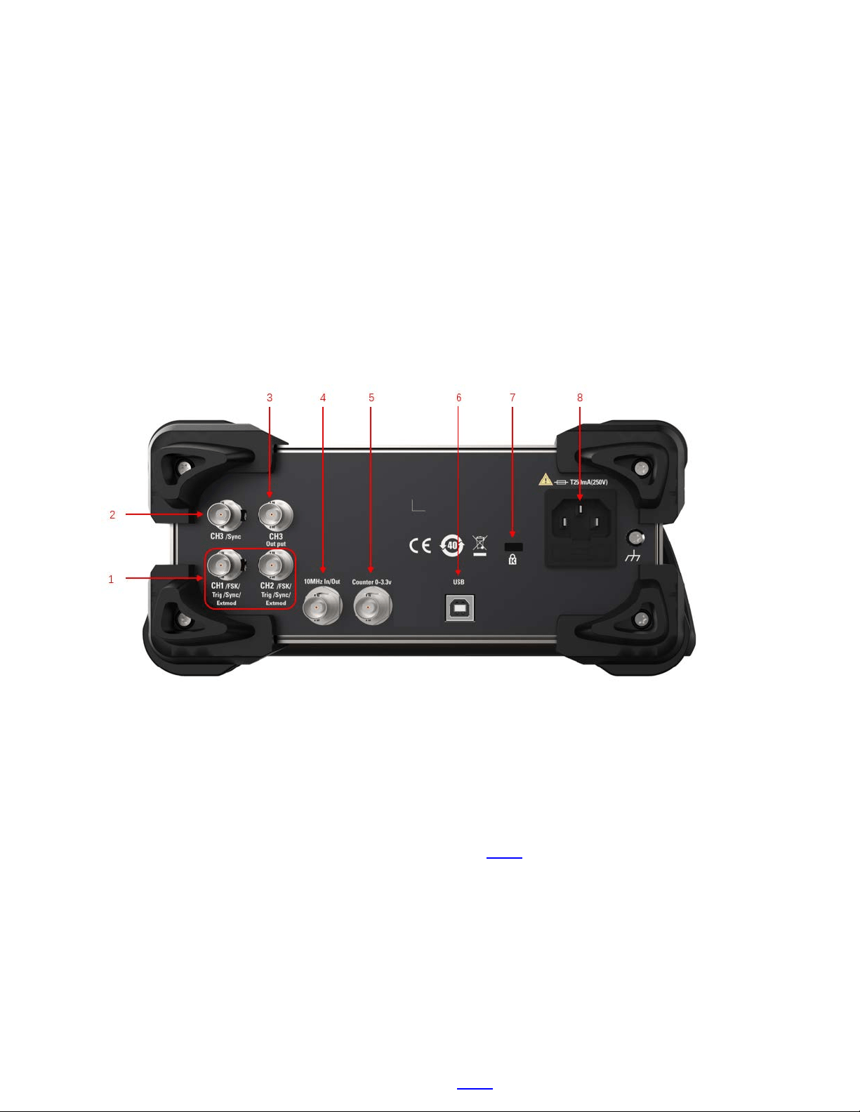
1.3Rear Panel
1. CH1/CH2 Sync/ExtMod/TrigConnector
BNC connector with 50Ωnominal output impedance and 1KΩnominal input impedance.
Its function is determined by the current working mode.
Sync:
When 1Outputis enabled, this connector outputs the sync signal corresponding to the
current settings of CH1 (refer to the introduction in
Sync).
ExtMod:
If modulation mode is enabled for CH1, and external modulation source is used, this
connector accepts an external modulation signal.
Trig:
If CH1 is in sweep or burst mode and external trigger source is used, this connector
accepts an external trigger signal (the polarity of the signal can be set).
2. CH3 SYNC Output Connector
BNC connector with 50Ω nominal output impedance.
When CH3 output is turned on, the connector outputs the sync signal corresponding to the
current settings of CH3 (refer to the introduction in
Sync).
User Manual 9
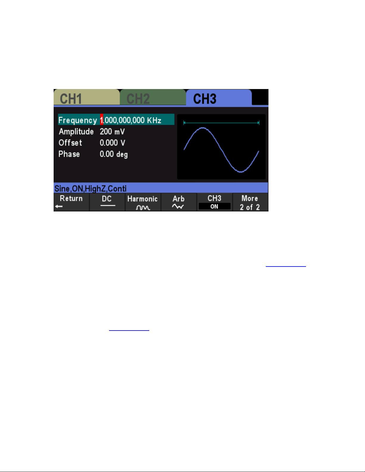
3. CH3 Output Connector
BNC connector with 50Ω nominal output impedance.
When CH3 output is turned on (press [CH1/2/3] to select the CH3 window display, then press
CH3 softkey and switch to "ON"), the corresponding connector outputs the configured
waveform.
4. 10 MHz Reference In/Out (10MHz In/Out)
BNC connector with 50Ω nominal output impedance and 5KΩ nominal input impedance. The
function of this connector is determined by the type of clock used by the generator.
HDG3000B(C) can use internal or external clock (refer to the introduction in "
Clock Source").
When internal clock source is used, the connector (used as 10MHz Out) can output
10MHz clock signal generated by the internal crystal oscillator of the generator.
When external clock source is used, the connector (used as 10MHz In) accepts a 10MHz
external clock signal.
This connector is usually used to synchronize multiple instruments (refer to the
introduction in "
Clock Source").
5. Counter (0~3.3V, external signal input)
BNC connector with 500Ω nominal input impedance. It is used to accept an external signal to
be measured by the counter.
6. USB DEVICE Interface
7. Safety Lock Hole
8. AC Power Socket
User Manual 10
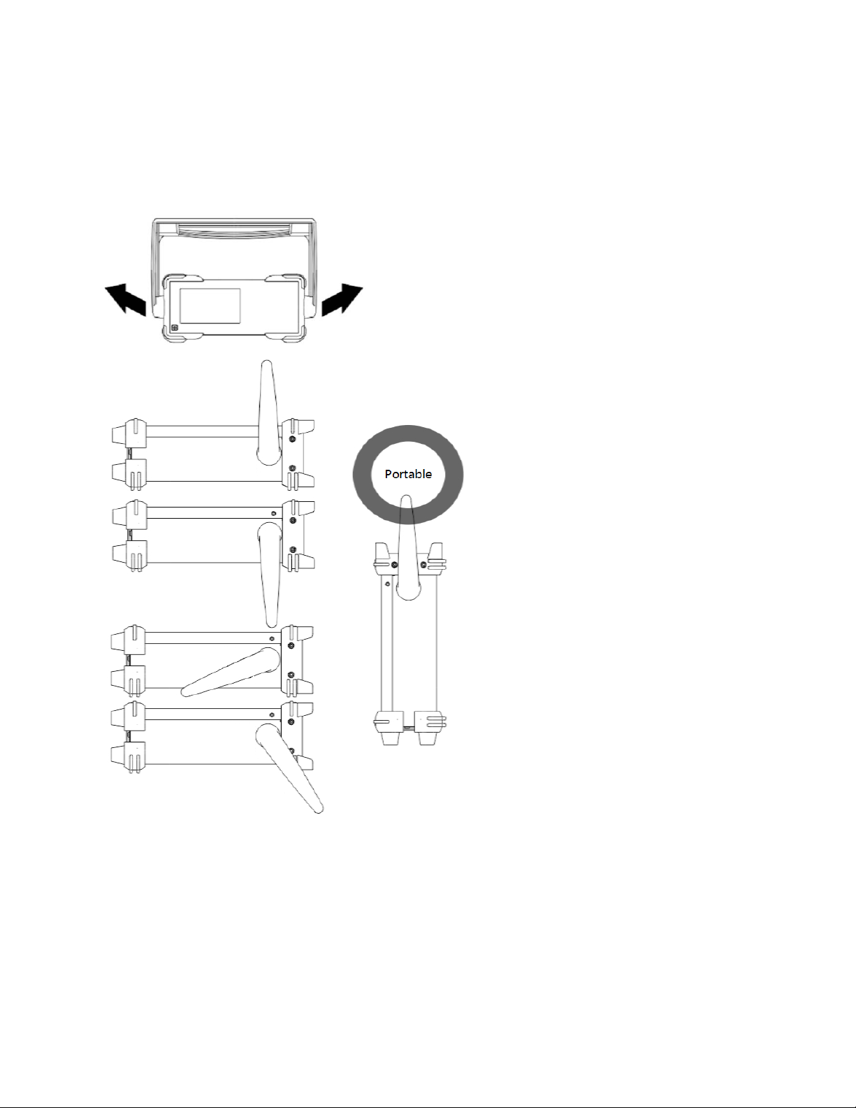
1.4 Prepare Instrument for Use
Adjust the Handle
To adjust the handle of the instrument, hold both sides of the handle and pull them outward, then
rotate the handle.
Connect to AC power cord
Connect the power cord as required.
This instrument can accept the power supply of 100-120VAC (±10%), 45-440 Hz or 120-240VAC
(±10%), 45-66Hz. Please use the power cord supplied with the accessories to connect the
instrument to the power supply.
Press the power switch on the front panel to turn on the instrument. If the instrument is not turned
on, make sure that the power cord is securely connected. Also make sure that the instrument is
connected to an energized power source.
Power Switch:
User Manual 11
To turn off the instrument, press the power switch.
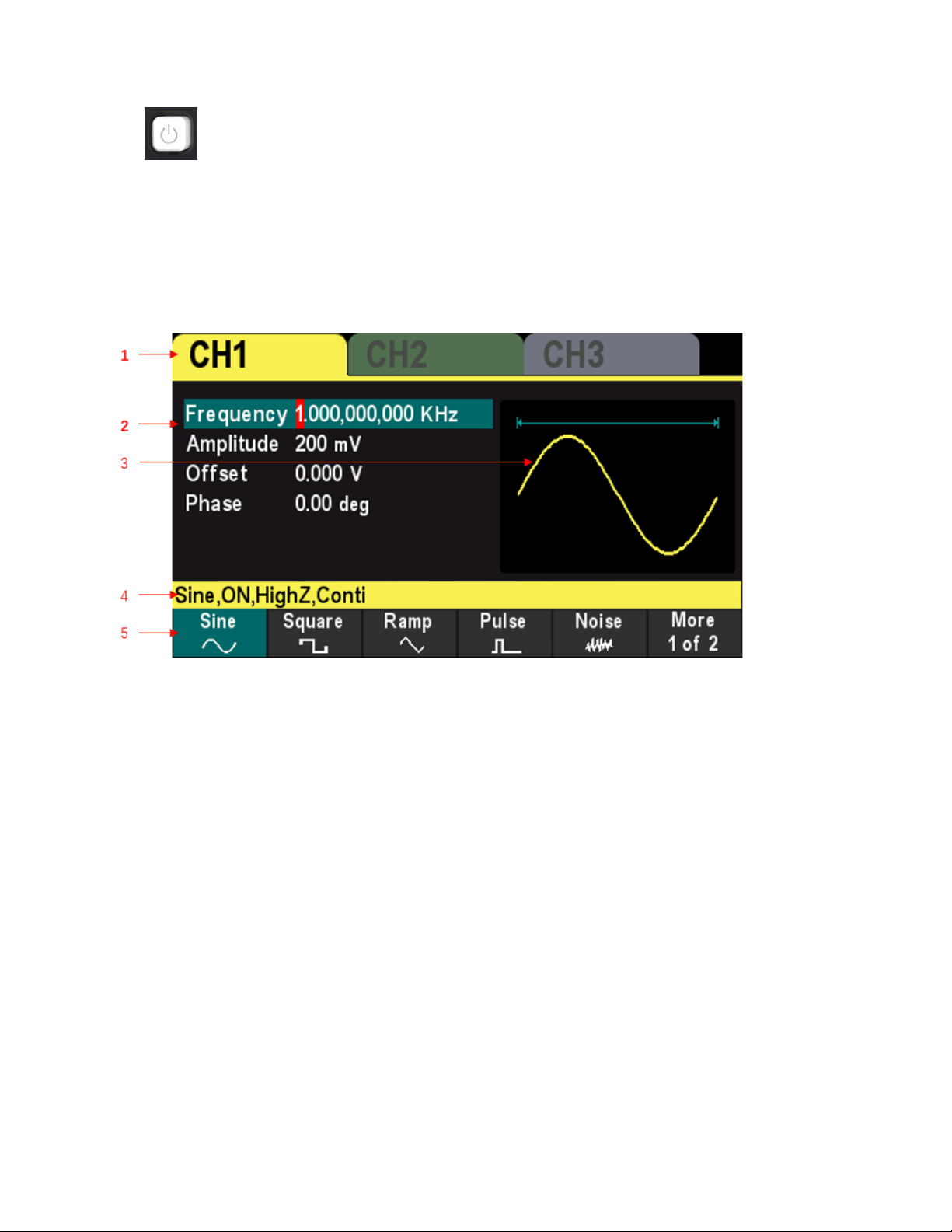
1.5 The User Interface
Theuser interface is shown in the following figure.
1. Displays the selected channel.Only HDG3000C supports CH3 output.
2. Channel Parameters
Display the waveform parameters of the current channel.
Press the parameter softkey and use the numeric keypad or direction keys and knob to modify
the value. The parameters that can be modified will be highlighted, and the red background of
the number indicates the current cursor position.
3. Waveform
Display the selected waveform type of the current channel.
4. Channel Configuration
Displays the output configuration of the current channel, including waveform type, output
impedance, operating mode and output state.
Output Impedance: HighZ (High Impedance) or 50Ω.
Mode: Modulation, Sweep, Burst orContinuous output.
5. Menu
Displays the operation menu corresponding to the currently selected function. For example,
the function menu of the "Wave" button is displayed in the figure.
User Manual 12
1.6 Parameter Setting Method
Users can use the numeric keypad or knob and direction keys to set parameters.
1.6.1 Numeric Keypad
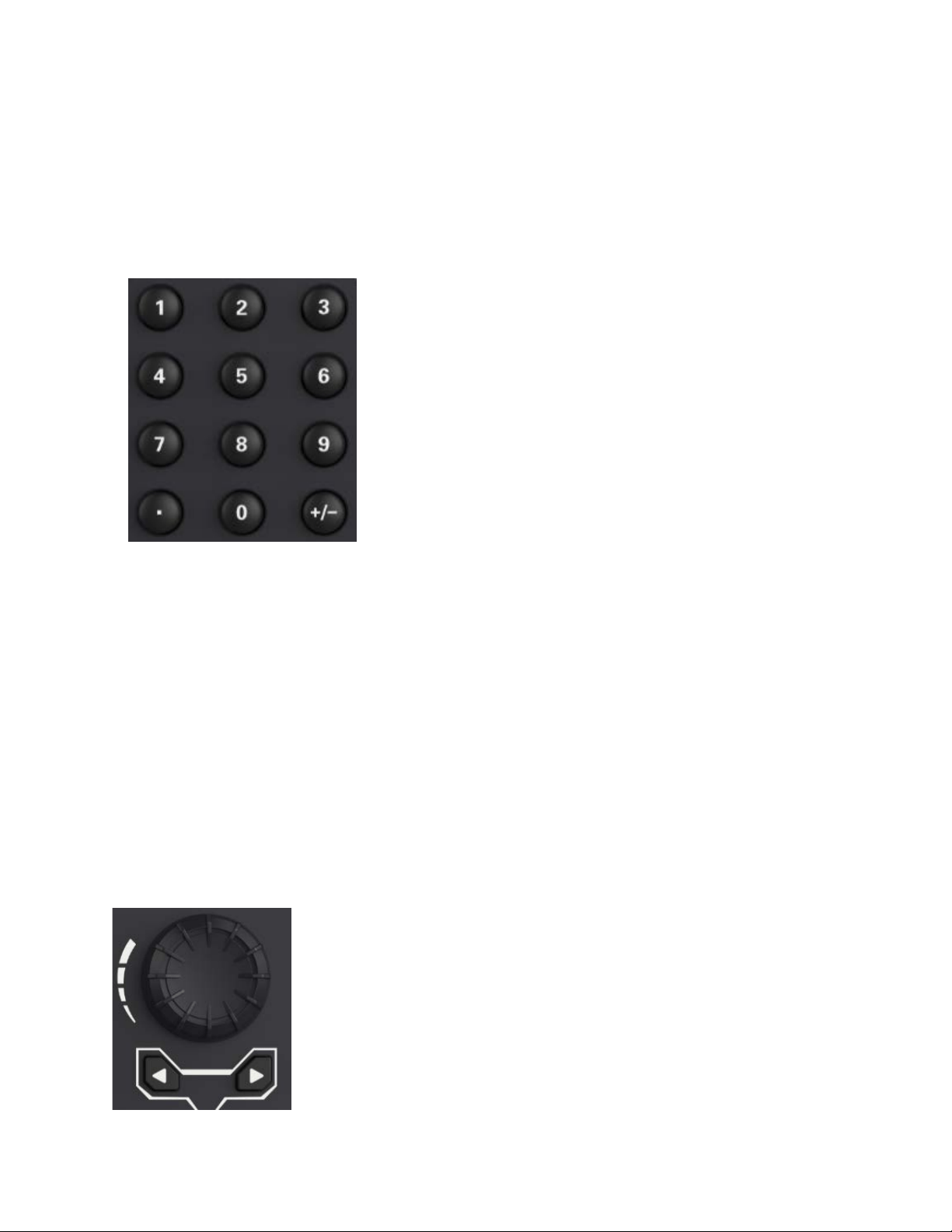
The numeric keypad consists of the following parts:
Number keys
The 0 to 9 number keys are used to directly input the desired parameter value.
Decimal point
Press this key to insert a decimal point "." at the current position of the cursor.
Operator Key
The operator key "+/-" is used to modify the operator of the parameter. Press this key to set the
parameter operator to "-".
1.6.2 DirectionKeys and Knob
Functions of the direction keys:
During parameter input, use the direction keys to move the cursor to select the digit to be
User Manual 13

edited.
During filename edit, use the direction keys to move the cursor.
Functions of the knob:
When the parameter is in editable state, turn the knob to increase (clockwise) or reduce
(counterclockwise) the parameter with specified step.
During filename edit, use the knob to select the characters in the soft keyboard.
In
[Wave] >Arb >Type >User, use the knob to select arbitrary waveform.
In store and recall, use the knob to select the storage location of the file or to select the file to
be recalled.
1.7 Help
To get help information for any front panel keys or menu softkeys, press Helpbutton on the front
panel, and then press the button or softkey you need to get help information for.
If there are indexes for other topics in the content view, users can rotate the knob to choose a
different index and press the knob to enter the corresponding topic content.
PressHelpbutton again to exit.
Help Button:
User Manual 14

Chapter 2 Basic Waveform Output
HDG3000B(C) can output basic waveforms (including Sine, Square, Ramp, Pulse and Noise)
from one of the channels separately or from the two channels at the same time.At start-up, the
channel is configured as a sine waveform with 1KHz frequency and 200mVpp amplitude by
default. This chapter introduces how to configure the instrument to output various basic
waveforms.
Select the Channel
Set theParameter
Basic Waveform Output Example
User Manual 15

2.1 Select the Channel
Users can configure HDG3000B(C) to output basic waveform from a single channel or from dual
channels at the same time. Please select the desired channel before configuring waveform
parameters. At start-up, CH1 is selected by default.
Press [CH1/2] or [CH1/2/3] button on the front panel and the corresponding area in the user
interface is illuminated. At this point, users can configure the waveform and parameters of the
channel selected.
Note: CH1 and CH2 cannot be selected at the same time. Users can first select CH1 and then
select CH2 after configuring the waveform and parameters of CH1.
2.2 Set theParameter
2.2.1 Select the BasicWaveform
HDG3000B(C) can output 5 kinds of basic waveforms, including Sine, Square, Ramp, Pulse and
Noise.At start-up, Sine is selected by default.
Press [Wave] button on the front panel, and then press the corresponding softkey in the menu to
select the waveform and enter the parameter setting menu.Now the user interface displays the
selected waveform shape.
Press [Wave] > CH1=CH2 softkey to change the settings of another channel to be the same as
the settings of the current channel.
2.2.2 Set the Frequency
Frequency is one of the most important parameters of the basic waveforms. For different models
and different waveforms, the setting ranges of the frequency are different. For detailed information,
please refer to "Frequency Characteristics" in "
Specifications". The default frequency is 1 KHz.
The frequency displayed on the screen is the default value or the frequency previously set. When
the instrument function is changed, if this frequency is valid under the new function, the
instrument will still use this frequency; otherwise, the instrument would display prompt message
and set the frequency to the frequency upper limit of the new function automatically.
Press [Setting] >Frequency softkey.At this point, use the numeric keypad to input the value of
the frequency and select the desired unit from the pop-up unit menu, or use the direction keys and
knob to modify the current value.
1. For the input method of frequency value, please refer to the introduction of "
Parameter Setting
Method".
2. The frequency units available are MHz, KHz, Hz and mHz.
3. Press [Utility] >Unit softkey and press Frequency/Period softkey to switch Frequency in the
parameter to Period.Press [Setting] >Period softkey to modify the period parameter.
4. The period units available are sec, msec, μsec and nsec.
User Manual 16
2.2.3 Set the Amplitude
The amplitude range is limited by Frequency or Period and Impedance settings. Please refer to
"Output Characteristics" in "
Specifications". The default value is 200mVpp.
The amplitude displayed on the screen is the default value or the amplitude previously set. When
the instrument configuration (e.g. frequency) is changed, if this amplitude is valid, the instrument
will still use this amplitude; otherwise, the instrument would display a prompt message and set the
amplitude to the amplitude upper limit of the new configuration automatically.
Press [Setting] >Amplitude softkey.At this point, use the numeric keypad to input the value of
the amplitude and select the desired unit from the pop-up unit menu, or use the direction keys and
knob to modify the current value.
1. For the input method of amplitude value, refer to the introduction in "
Parameter Setting
Method".
2. The amplitude units available are Vpp, mVpp, and Vrms, dBm (50Ω impedance).
3. Press [Utility] >Unit softkey and press Amplitude/High Level softkey to switch the Amplitude
and Offset in the parameter to High Level and Low level. Press [Setting] >High Level or Low
Levelsoftkey to modify high level or low level parameters.
4. The high level units available are V and mV.
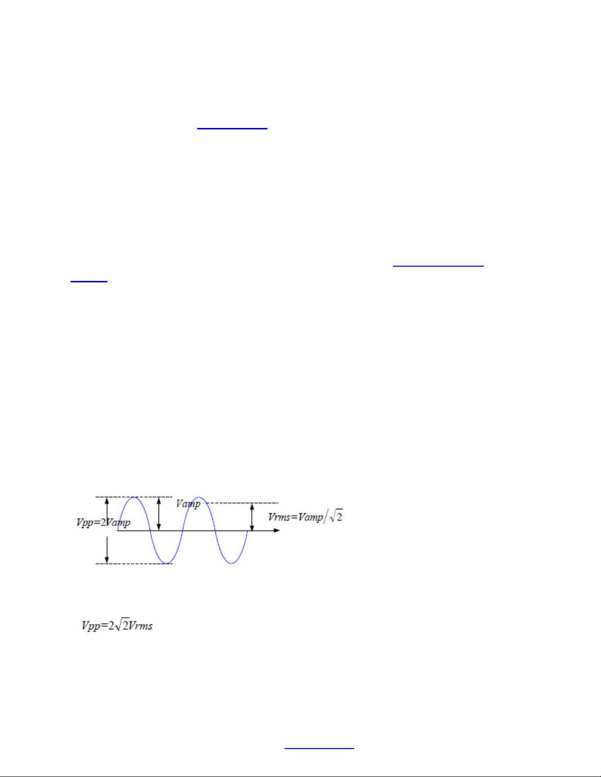
Tips:
Switch between Vpp and Vrms
Vpp is the unit for the signal peak-peak value and Vrms is the unit for the signal effective value.
The default unit of the instrument is Vpp. Users can quickly switch the current amplitude unit from
the front panel.
For different waveforms, the relations between Vpp and Vrms are different. Take sine waveform
as an example; the relation of the two units is as shown in the figure below.
According to the figure above, the conversion relation between Vpp and Vrms fulfills the following
equation.
For example, convert 2Vpp to the corresponding value in Vrms.
For sine waveform, press in the numeric keypad to enter 0.707 and select the Vrms menu.
2.2.4 Set the DC Offset Voltage
The settable range of the DC offset voltage is limited by the Amplitude and Impedance settings.
Please refer to the "Output Characteristics" in "
Specifications". The default value is 0VDC.
User Manual 17
Press [Setting] >Offsetsoftkey.At this point, use the numeric keypad to enter the offset value and
select the desired unit from the pop-up unit menu, or use the direction keys and knob to modify
the current value.
1. For the input method of offset value, refer to the introduction in "
Parameter Setting Method".
2. The DC offset voltage units available are V and mV.
3. Press [Utility] >Unitsoftkey and press Offset/Low Level softkey to switch Amplitudeand
Offset in the parameter to High and Low level. Press [Setting] >High level or Low levelsoftkey
to modify high-level or low-level parameters.
4. The low level units available are V and mV.
2.2.5 Set the Start Phase
Press [Setting] >Phasesoftkey to enter the phase submenu.At this point, use the numeric keypad
to input the value of the phase and select the unit " Degree" from the unit menu that pops up, or
use the direction keys and the knob to modify the current value.
1. For the input method of phase value, refer to the introduction in "
Parameter Setting Method".
2. The starting phase can be set from 0° to 360°.The default value is 0°.
3. Press 0 phase softkey to quickly set the phase to 0°.
4. Press SYNC softkey to synchronize the phase of the two channels (CH1 and CH2) with each
other.
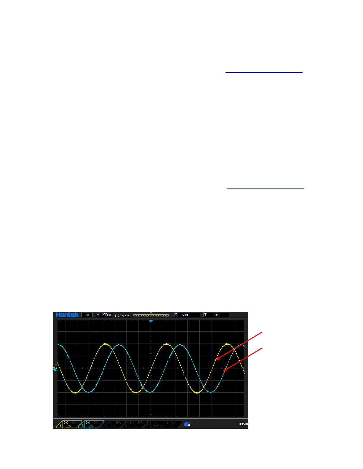
For two signals whose frequencies are the same or in multiple, this operation will align their
phases. For example, assume a sine waveform (1KHz, 8Vpp, 0 °) is output from CH1, while
another (1KHz, 8Vpp, 180°) from CH2. Use an oscilloscope to sample and display the waveforms
of the two channels. You will see that the phase deviation of the two waveforms displayed on the
oscilloscope is not 180°. At this point, press SYNC softkeyon the generator and the waveforms
shown on the oscilloscope will have a phase deviation of 180° without any adjustment of the start
phase of the generator.
Before synchronizing phase:
CH1
CH2
User Manual 18
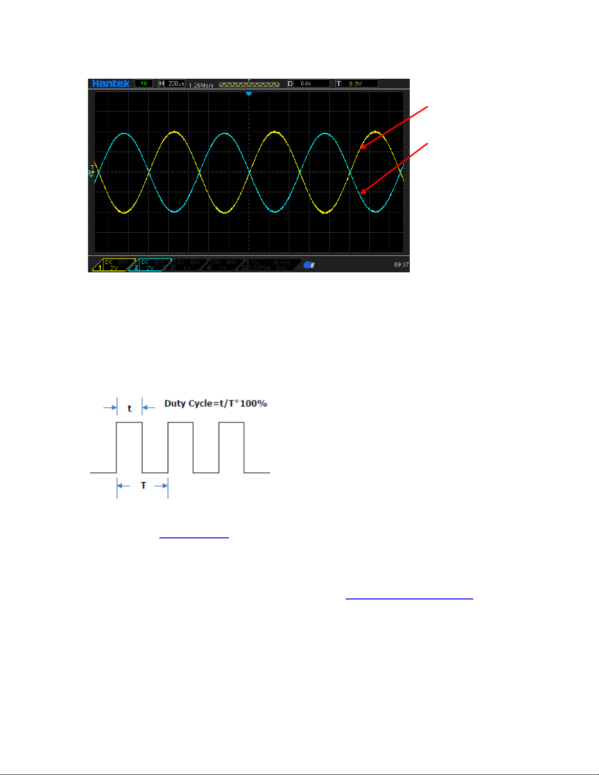
After synchronizing phase:
2.2.6 Set the Duty Cycle
Duty cycle is defined as the percentage that the high level takes up in the whole period as shown
in the figure below.
The duty cycle range is limited by the "Frequency/Period" setting. Please refer to "Signal
Characteristics" in "
Specifications". The default value is 50%.
Press [Wave] > Squaresoftkey to select the square waveformfunction and press Duty softkey to
highlight it.At this point, use the numeric keypad to input the value and select the unit "%" from the
unit menu that pops up, or use the direction keys and the knob to modify the current value.For the
input method of duty cycle value, refer to the introduction in "
Parameter Setting Method".
2.2.7 Set the Symmetry
Symmetry is defined as the percentage that the rising period takes up in the whole period as
shown in the figure below. This parameter is only available when ramp is selected.
CH1
CH2
User Manual 19

Symmetry can be set in the range of 0% to 100%.The default value is 50%.
Press [Wave] >Rampsoftkey to select the rampwave function and press Symmetrysoftkey to
highlight it.At this point, use the numeric keypad to input the value and select the unit "%" from the
unit menu that pops up, or use the direction keys and the knob to modify the current value.For the
input method of symmetry value, refer to the introduction in "
Parameter Setting Method".
2.2.8 Set the Pulse Parameters
To output a pulse, users need to set the "Width/Duty", "Leading" and "Trailing", in addition to the
basic parameters (such as the frequency, amplitude, DC offset voltage, high level, low level and
align phase) introduced above.
Pulse width/duty cycle
Pulse width is defined as the time from the 50% threshold of a rising edge amplitude to the 50%
threshold of the next falling edge amplitude as shown in the figure above.
The settable range of the pulse width is limited by the "Minimum Pulse Width" and the "Pulse
Period" (for the ranges of the "Minimum Pulse Width" and "Pulse Period", please refer to "Signal
Characteristics" in "
Specifications"). The default value is 100μs.
1. Pulse Width Minimum P uls e Width
2.Pulse Width P uls e P e riod - Minimum Pulse Width
Pulse duty cycle is defined as the percentage that the pulse width takes up in the whole pulse
User Manual 20

period.
The pulse width and pulse duty cycle are correlative. Once a parameter is changed, the other will
be automatically changed. The pulse duty cycle is limited by the "Minimum Pulse Width" and
"Pulse Period".
1. Pulse Duty Cycle Minimum P uls e Width ÷ P ulse Period × 100%
2. Pulse Duty Cycle (1 - Minimum Pulse Width ÷ Pulse Period) × 100%
Press [Wave] > Pulsesoftkey to select the pulse wave function and press Width softkey to
highlight it.At this point, use the numeric keypad to input the value and select the desired unit from
the unit menu that pops up, or use the direction keys and knob to modify the current value.
1. For the input method of the value, refer to the introduction in "Parameter Setting Method".
4. The width units available are sec, msec, μsec and nsec.
3.Press [Utility] > unitsoftkey and press Width/Dutysoftkey to change Width in the parameter to
Duty.Press [Setting] >Dutysoftkey to modify the duty cycle parameters.
Leading/Trailing Edge Time
The leading (rising) edge time is defined as the time required for the pulse amplitude to rise from
10% threshold to 90% threshold; while the trailing (falling) edge time is defined as the time
required for the pulse amplitude to fall from 90% threshold to 10% threshold as shown in the
figure above.
The range of the leading/trailing edge time is limited by the pulse width currently specified as
shown in the formula below. The edge time will be automatically adjusted to match the specified
pulse width if the value currently set exceeds the limit value.
Leading/Trailing Edge Time ≤ 0.625 × Pulse Width
Press [Wave] > Pulsesoftkey to select pulse wave function and press Edge Time softkey to enter
the Edge Time sub-menu.Press Leading or Trailing softkey to highlight it.At this point, use the
numeric keypad to input the value and select the desired unit from the unit menu that pops up, or
use the direction keys and knob to modify the current value.
1. For the input method of the value, refer to the introduction in "
Parameter Setting Method".
2. The edge time units available are sec, msec, μsec and nsec.
3. The leading time and trailing time are independent from each other and users can set them
separately.
2.2.9 Enable the Channel Output
After configuring the parameters of the waveform selected, waveform output could be enabled.
Press[Output1] or/and [Output2] button on the front panel and the backlight of the button turns
on. The instrument outputs the configured waveform from the [Output1] or [Output2] connector
on the front panel.
User Manual 21
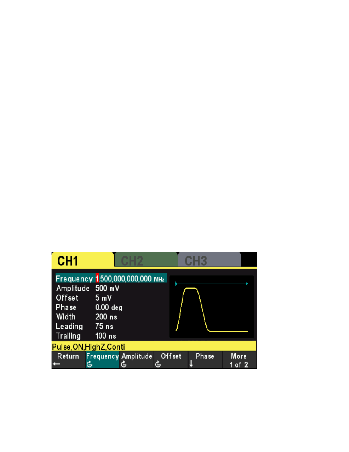
2.3 Basic Waveform Output Example
Configure the generator to output a pulse waveform with 1.5MHz frequency, 500mVpp amplitude,
5mV
DC DC offset, 200ns pulse width, 75ns leading edge time and 100ns trailing edge time.
1. Press [CH1/2/3] button on the front panel and select CH1.The corresponding area of CH1 in
the user interface is illuminated.
2. Press [Wave] > Pulsesoftkey to select the pulse wave function.
3. PressFrequency softkey to highlight it.Use the numeric keypad to input the frequency value
"1.5", and then select the desired unit "MHz" from the pop-up menu.
4. Press Amplitude softkey to highlight it.Use the numeric keypad to input the amplitude value
"500", and then select the desired unit "mVpp" in the pop-up menu.
5. Press Offset softkey to highlight it.Use the numeric keypad to input the offset value "5", and
then select the desired unit "mV" in the pop-up menu.
6. Press Width softkey to highlight it.Use the numeric keypad to input the width value "200", then
select the unit "nsec" from the menu that pops up.
7. Press Edge Time softkey to enter the edge time submenu.Press Leading softkey to highlight
it.Use the numeric keypad to enter the value "75", then select the unit "nsec" from the menu
that pops up.
8. Press Edge Time softkey to enter the edge time submenu.Press Trailing softkey to highlight
it.Use the numeric keypad to enter the value "100", then select the unit "nsec" from the menu
that pops up.
9. Press [Output1] button on the front panel to turn CH1 Output on.
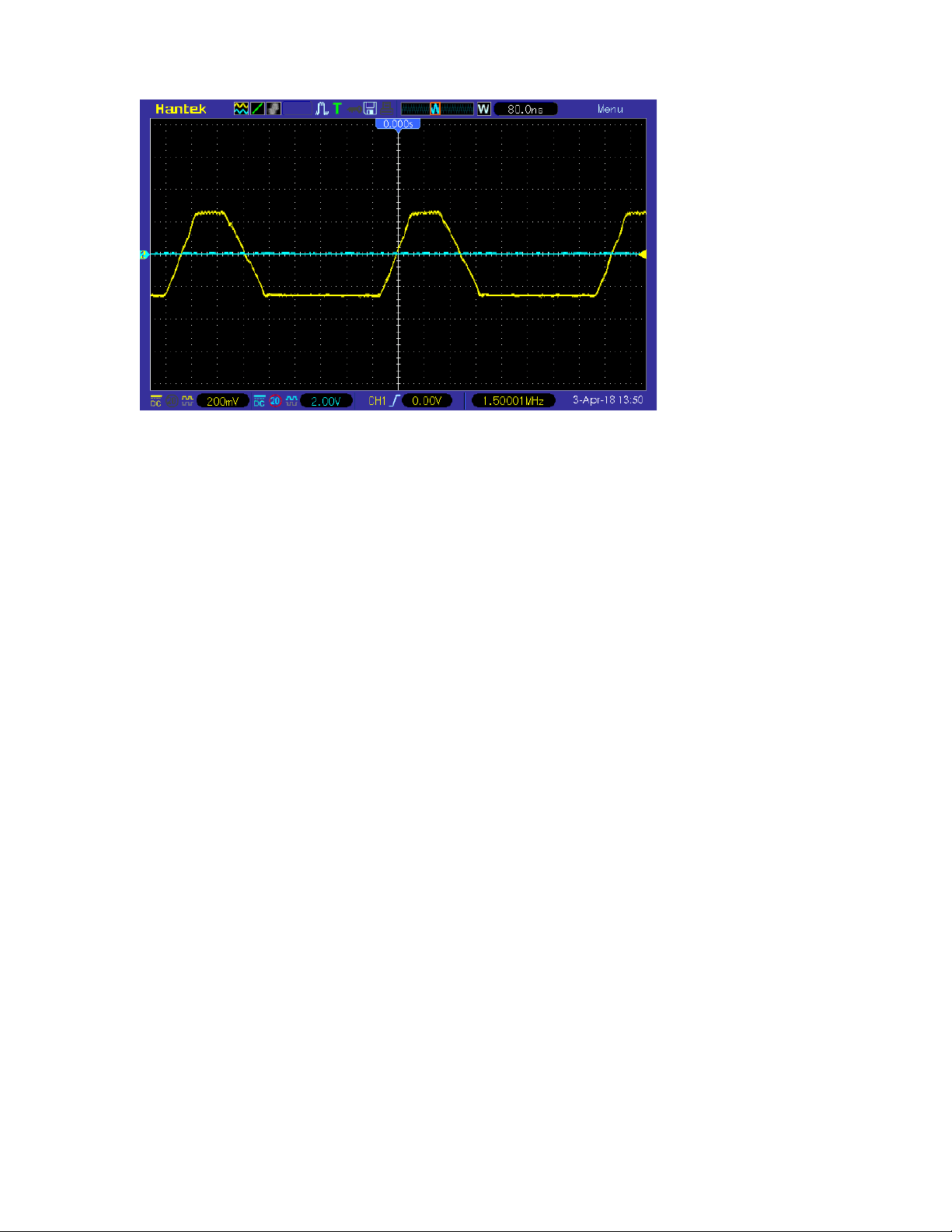
10. At this point, the specified waveform is output from CH1 based on the current
configuration.Connect the CH1 output terminal to the oscilloscope and the waveform is as
shown in the figure below.
User Manual 22
User Manual 23

Chapter 3 Arbitrary Waveform Output
HDG3000B(C) can output the built-in waveforms and user-defined arbitrary waveforms from a
single channel or from two channels at the same time.The 160 kinds of built-in waveforms are
stored in the internal non-volatile memory. The user-defined arbitrary waveforms can contain 64
to 2M data points. Users can edit the arbitrary waveforms via the PC software and then download
them to the instrument.
This chapter introduces how to configure the generator to output arbitrary waveforms.
Enable Arbitrary Waveform
Select Arbitrary Waveform
User Manual 24
3.1 Enable Arbitrary Waveform
Press [Wave] >Arb softkey to enable the arbitrary waveformfunction and open the operation
menu of thearbitrary waveform.
To set the basic parameters of arbitrary waveforms, refer to “Set the Parameters”.
Type: Select the built-in waveforms or user-defined arbitrary waveform stored in external storage.
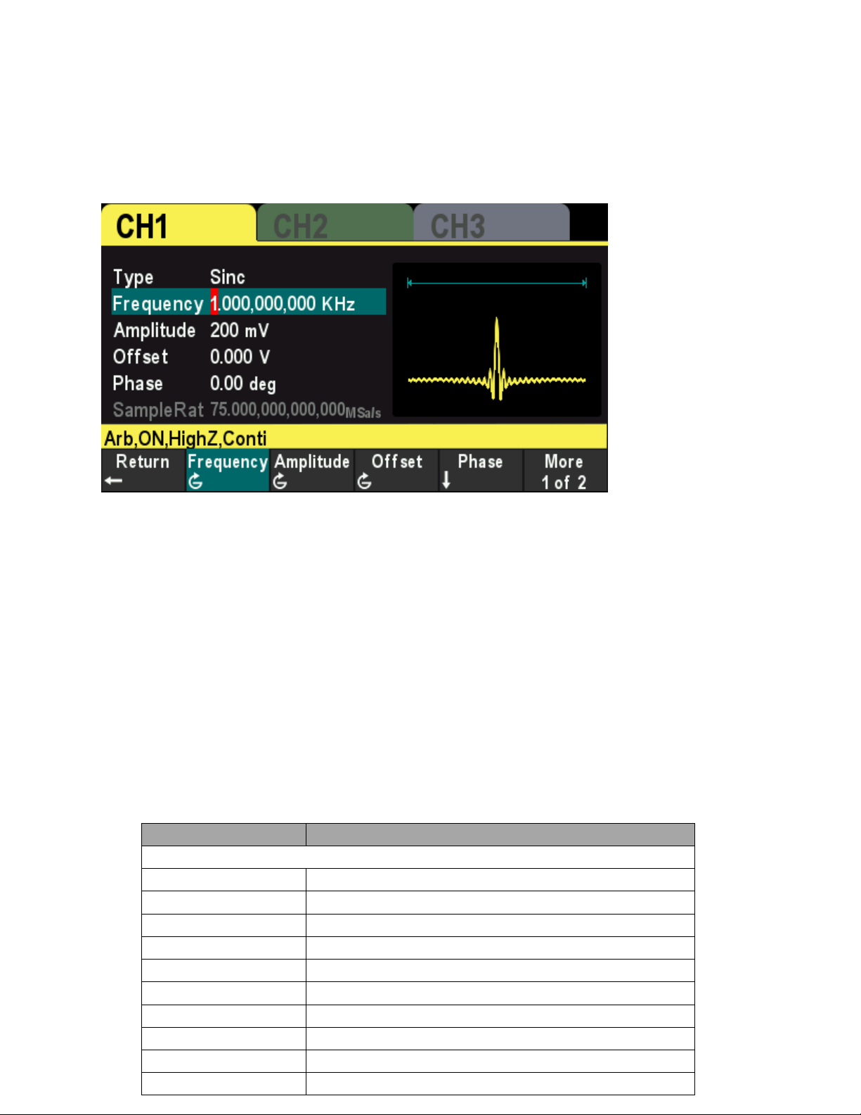
3.2 Select Arbitrary Waveform
The HDG3000B(C) allows the user to select arbitrary waveform in the internal or external memory
of the instrument for output.
Press [Wave] >Arb>Typesoftkeyto select the built-in waveform.
Select more than 160 kinds of arbitrary waveform built in HDG3000B(C), as shown in the
following table.Press the softkey and select a type ("Math", "Project", "Distribution function" and
"Trigonometric function", "Window function" and "biology"), and press the corresponding softkey
type to select the desired waveform.
Build-In Waveform
Name
Description
Common
DC DC signal
AbsSine Absolute value of a Sine
AbsSineHalf Absolute value of half a Sine
AmpALT
Gain oscillation curve
AttALT
Attenuation oscillation curve
GaussPulse
Gauss pulse
NegRamp
Negative ramp
NPulse
Negative pulse
PPulse Positive pulse
SineTra Sine-Tra waveform
User Manual 25

SineVer Sine-Ver waveform
StairDn
Stair-down waveform
StairUD
Stair-up and stair-down waveform
StairUp
Stair-up waveform
Trapezia
Trapezoid waveform
Project
BandLimited Bandwidth-limited signal
BlaseiWave Time-velocity curve of explosive vibration
Butterworth Butterworth filter
Chebyshev1 Chebyshev1 filter
Chebyshev2 Chebyshev2 filter
Combin
Combination function
CPulse
C pulse
CWPulse
CW pulse
DampedOsc
Time-displacement curve of damped oscillation
DualTone
Dual-tone signal
Gamma Gamma signal
GateVibar Gate self-oscillation signal
LFMPulse Linear FM pulse
MCNoise Mechanical construction noise
Discharge Discharge curve of Ni-MH battery
Pahcur
Current waveform of DC brushless motor
Quake
Analog quake waveform
Radar
Analog radar waveform
Ripple
Ripple wave of battery
RoundHalf RoundHalf wave
RoundsPM RoundsPM waveform
StepResp Step-response signal
SwingOsc Kinetic energy- time curve of swing oscillation
TV TV signal
Voice Voice signal
Sec-Mod
AM
Sectioned sine AM signal
FM
Sectioned sine FM signal
PFM
Sectioned pulse FM signal
PM Sectioned sine PM signal
PWM Sectioned PWM signal
Bioelect
Cardiac Cardiac signal
EOG Electro-Oculogram
EEG Electroencephalogram
EMG
Electromyogram
Pulseilogram
Pulsilogram
ResSpeed
Speed curve of the respiration
User Manual 26

Medical
LFPulse
Waveform of the low frequency pulse electrotherapy
Tens1
Waveform 1 of the nerve stimulation electrotherapy
Tens2
Waveform 2 of the nerve stimulation electrotherapy
Tens3
Waveform 3 of the nerve stimulation electrotherapy
Standard
Ignition Ignition waveform of the automotive motor
ISO16750-2 SP Automotive starting profile with ringing
ISO16750-2 VR Automotive supply voltage profile for resetting
ISO7637-2 TP1 Automotive transients due to disconnects
ISO7637-2 TP2A Automotive transients due to inductance in wiring
ISO7637-2 TP2B
Automotive transients due ignition switching off
ISO7637-2 TP3A
Automotive transients due to switching
ISO7637-2 TP3B
Automotive transients due to switching
ISO7637-2 TP4
Automotive supply profile during starting
ISO7637-2 TP5A
Automotive transients due to battery disconnect
ISO7637-2 TP5B Automotive transients due to battery disconnect
SCR SCR firing profile
Surge Surge signal
Math
Airy Airy function
Besselj
BesselI function
Bessely
BesselII function
Cauchy
Cauchy distribution function
Cubic
Cubic function
Dirichlet Dirichlet function
Erf Error function
Erfc Complementary error function
ErfcInv Inverted complementary error function
ErfInv Inverted error function
ExpFall Exponential fall function
ExpRise
Exponential rise function
Gauss
Gauss distribution
HaverSine
HaverSine function
Laguerre
4-times Laguerre polynomial
Laplace Laplace distribution
Legend 5-times Legend polynomial
Log Logarithm function with the base 10
LogNormal Logarithmic Gaussian distribution
Lorentz Lorentz function
Maxwell Maxwell distribution
Rayleigh
Rayleigh distribution
Versiera
Versiera
Weibull
Weibull distribution
User Manual 27

ARB_X2 Square function
Trigonome
CosH
Hyperbolic cosine
CosInt
Integral cosine
Cot
Cotangent
CotHCon Concave hyperbolic cotangent
CotHPro Protuberant hyperbolic cotangent
CscCon Concave cosecant
CscPro Protuberant cosecant
CscHCon Concave hyperbolic cosecant
CscHPro Protuberant hyperbolic cosecant
RecipCon
Concave reciprocal
RecipPro
Protuberant reciprocal
SecCon
Concave secant
SecPro
Protuberant secant
SecH
Hyperbolic secant
Sinc Sinc function
SinH Hyperbolic sine
SinInt Integral sine
Sqrt Square root
Tan Tangent
TanH
Hyperbolic tangent
Anti Trigonome
ACos
Arc cosine
ACosH
Arc hyperbolic cosine
ACotCon Concave arc cotangent
ACotPro Protuberant arc cotangen
ACotHCon Concave arc hyperbolic cotangent
ACotHPro Protuberant arc hyperbolic cotangent
ACscCon Concave arc cosecant
ACscPro Protuberant arc cosecant
ACscHCon
Concave arc hyperbolic cosecant
ACscHPro
Protuberant arc hyperbolic cosecant
ASecCon
Concave arc secant
ASecPro
Protuberant arc secant
ASecH Arc hyperbolic secant
ASin Arc Sinc
ASinH Arc hyperbolic sine
ATan Arc tangent
ATanH Arc hyperbolic tangent
Window
Bartlett
Bartlett window
BarthannWin
Modified Bartlett-Hann window
Blackman
Blackman window
User Manual 28

BlackmanH BlackmanH window
BohmanWin
Bohman window
Boxcar
Rectangle window
ChebWin
Chebyshev window
FlattopWin
Flat Top weighted window
Hamming Hamming window
Hanning Hanning window
Kaiser Kaiser window
NuttallWin Nuttall-defined minimum 4-term Blackman-Harris window
ParzenWin Parzen window
TaylorWin Taylor window
Triang
Triangle window (Fejer window)
TukeyWin
Tukey (tapered cosine) window
User-definedWaveforms
Select the user-defined arbitrary waveform stored in external storage (USB drive).
Loading arbitrary waveform
Edit the ARB waveformby PC software and exportthe waveform data to the external storage
device as .hwf file.
Press [Wave] >Arb softkey to enter the arbitrary menu, and press Type >User softkeyto select
the arbitrary waveform file to load.
User Manual 29

Chapter 4 Harmonic Output
The HDG3000B(C) can be used as a harmonic generator to output harmonic with specified order,
amplitude and phase. It is usually used in the test of harmonic detector device or harmonic filter
device.
This chapter introduces how to configure the generator to output harmonics. Subjects in this
chapter:
Overview
Set the Basic Waveform Parameters
Set the Harmonic Order
Select the Harmonic Type
Set the Harmonic Amplitude
Set the Harmonic Phase
User Manual 30

4.1 Overview
According to Fourier transform, time domain waveform is the superposition of a series of sine
waveforms as shown in the equation below:
Generally, component with
f
1
frequency is called basic waveform, f
1
is basic waveform frequency,
A
1
is basic waveform amplitude and φ
1
is basic waveform phase. The frequencies of other
components (called harmonics) are all integral multiples of the basic waveform frequency.
Components whose frequencies are odd multiples of the basic waveform frequency are odd
harmonics and components whose frequencies are even multiples of the basic waveform
frequency are even harmonics.
HDG3000B(C) can output up to 16th order of harmonic. After selecting CH1 or CH2, press
[Wave] > Harmonic softkey on the front panel to enter the harmonic setting menu. Users can set
the parameters of basic waveform, set the type of harmonic, specify the highest order of harmonic
and set the amplitude and phase of each order of harmonic.
After finishing harmonic parameter setting, press [Output1] button or (and) [Output2] button on
the front paneland the backlight of the button turns on, the instrument outputs the specified
harmonic from the corresponding output terminal.
4.2 Set the BasicWaveformParameters
Users can set various basic waveform parameters such as frequency, period, amplitude, DC
offset voltage, high level, low level and start phase. It also supports synchronizing phase
operation. Please refer to introductions in "
Basic Waveform Output" to set basic waveform
parameters.
4.3 Set the Harmonic Order
The highest order of harmonicoutput cannot be greater than this setting value.
Press [Wave]>Harmonicsoftkeyon the front panel to enter the harmonic setting menu, and press
Ordersoftkey, at this time, the "Order” on the screen is highlighted, use the numeric keypad or the
direction keys and the knob to input the corresponding value.The range is limited by the maximum
output frequency of the instrument as well as the basic waveform frequency.
Range: integers within 2 to maximum output frequency of the instrument ÷ basic
waveform frequency.
The maximum value is 16.
User Manual 31

4.4 Set the Harmonic Type
HDG3000B(C) can output even harmonics, odd harmonics or all orders of
harmonics.Press[Wave] >Harmonicsoftkey on the front panel to enter the harmonic setting menu,
and press Type softkey to select the desired harmonic type.
1. Even
Select this type and the instrument would output basic waveform and even harmonics.
2. Odd number
Select this type and the instrument would output basic waveform and odd harmonics.
3. All
Select this type and the instrument would output basic waveform and all the harmonics in
order.
Note: The harmonics actually output is determined by the "Order" currently specified.
4.5 Set the Harmonic Amplitude
Press [Wave] > Harmonic softkey to enter the harmonic setting menuand
pressAmplitudesoftkey to set the amplitude of each harmonic.
1. Index: Press thissoftkey to select the index number of the harmonic to be selected.
2. Amplitude: Press thissoftkey to set the amplitude of the selected subharmonic. Use the
numeric keypad to input the amplitude value and then select the desired unit from the pop-up
menu, or use the direction keys and knob to modify the current value.
For the input method of amplitude value, please refer to the introduction in "
Parameter
Setting Method".
The amplitude units available are Vpp and mVpp.
4.6 Set the Harmonic Phase
Press [Wave] > Harmonic softkey to enter the harmonic setting menuand pressPhasesoftkey to
set the phase of each harmonic.
1. Index: Press this softkey to select the index number of the harmonic to be selected.
2. Phase: Press thissoftkey to set the phase of the selected subharmonic.Use the numeric
keypad to input the phase value and then select the unit "°" from the pop-up menu, or use the
direction keys and knob to modify the current value. For the input method of phase value, refer to
the introduction in "
Parameter Setting Method".
User Manual 32

Chapter 5 Modulation
HDG3000B(C) supports AM, DSB-AM, FM, PM, 2ASK, 2FSK, 2PSK, BPSK, QPSK, 3FSK, 4FSK,
OSK and PWM modulations. It can output modulated waveform from a single channel or from two
channels at the same time. The modulated waveform consists of carrier waveform and modulating
waveform. The carrier waveform can be Sine, Square, Ramp, Pulse, Arbitrary waveform (except
DC)or Harmonic. The modulating waveform can be from internal (default), other channel, or
external modulation source.
AM Modulation
DSB-AM Modulation
FM Modulation
PM Modulation
2ASK Modulation
2FSK Modulation
2PSK Modulation
BPSK Modulation
QPSKModulation
3FSKModulation
4FSKModulation
OSK Modulation
PWM Modulation
User Manual 33

5.1 AMModulation
A modulated waveform consists of a carrier waveform and a modulating waveform. In AM, the
carrier amplitude is varied by the voltage level of the modulating waveform.
5.1.1 Select AM Modulation
Press [Mod] >Type > AMsoftkey to enable AM function.
When Mod is enabled, Sweep or Burst will be disabled automatically.
After AM is enabled, the instrument will generate AM waveform with the currently specified
carrier and modulating waveforms. To avoid multiple waveform changes, enable modulation
after configuring the other modulation parameters.
5.1.2 Carrier Waveform Shape
AM carrier shape: Sine (default), Square, Ramp, Pulse, Arbitrary (except DC) or Harmonic
waveform.
Press[Wave] button on the front panel to select the desired carrier waveform shape.
Noise and DC could not be used as carrier waveform.
5.1.3 Carrier Waveform Frequency
For different carrier waveforms, the settable range of carrier frequency is different.Please refer to
"Frequency Characteristics" in "
Specifications".The default value is 1kHz.
Press [Setting]>Frequencysoftkey on the front panel, and then use the numeric keypad or
direction keys and knob to input the desired frequency value.
5.1.4 Modulation Source
Press [Mod]>Signal Sourcesoftkey to select Internal, External or Another Channel as the
modulation source.
Internal Source
When internal modulation source is selected, pressShapesoftkey to select Sine, Square, Ramp,
Noise or Arb as the modulation source. The default is Sine.
Sine
Square: 50% duty cycle
Ramp: 50% symmetry.
Noise
Arb: Sinc, Exp Fall, Haver Sine, Lorentz, Gause, Dual Tone, ECG.
Note: Noise can be used as modulating waveform but cannot be used as carrier waveform.
User Manual 34

External Source
When external modulation source is selected, the Frequency and Shape menu in the modulation
menu is grayed out and disabled.The instrument receives the external modulation signal from the
[FSK/Trig/Sync/Extmod] connector on the rear panel.At this point, the AM modulation amplitude
is controlled by the ±4V signal level on this connector.For example,when the modulation depth is
100%, the output amplitude is maximum when the external modulation signal is +4V, and the
output amplitude is the minimum when the external modulation signal is -4V.
OtherChannels
CH1 and CH2 can be used as modulation sources reciprocally. When CH1 is used as the
modulated wave, CH2 can be used as the modulation source. And vice versa.
When selecting another channel as the modulation source, please turn on the output of that
channel.
5.1.5 Modulation Frequency
When internal modulation source is selected,press[Mod] >Frequencysoftkey to set the frequency
of the modulating waveform.
Use the numeric keypad or direction keys and knob to enter the desired frequency values.
The modulating waveform frequency range is 2mHz to 1MHz, and the default value is 100Hz.
Note: This menu will be grayed out and disabled when other modulation sources except the
internal modulation source are selected.
5.1.6 Modulation Depth
The modulation depth is a percentage that represents the amplitude variation.
Press [Mod]>Depthsoftkey to set AM modulation depth.
Modulation depth range: 0% to 120%. The default is 100%.
At 0% depth, the amplitude is one-half of the carrier’s amplitude setting.
At 100% depth, the output amplitude is equal to the specified value.
In >100% modulation, the output amplitude of the instrument would not exceed 10Vpp (50Ω
load).
When external modulation source is select, the output amplitude of the instrument is also
controlled by the ±4V signal level on the [FSK/Trig/Sync/Extmod] connector on the rear
panel.For example, set the modulation depth to 100%, the output amplitude is the maximum when
the modulating signal is +4V and the minimum when the modulating signal is -4V.
5.2 DSB-AM Modulation
In the Double-sideband AM signal, there are only two side frequencies, and there is no carrier
component. Its frequency bandwidth is still twice the frequency of the modulated signal.
User Manual 35

5.2.1 Select DSB-AM Modulation
Press [Mod] >Type > DSB-AMsoftkey to enable DSB-AM function.
When Mod is enabled, Sweep or Burst will be disabled automatically.
After DSB-AM is enabled, the instrument will generate DSB-AM waveform with the currently
specified carrier and modulating waveforms. To avoid multiple waveform changes, enable
modulation after configuring the other modulation parameters.
5.2.2 Carrier Waveform Shape
DSB-AM carrier shape: Sine (default), Square, Ramp, Pulse, Arbitrary (except DC) or
Harmonic waveform.
Press[Wave] button on the front panel to select the desired carrier waveform.
Noise and DC could not be used as carrier waveform.
5.2.3 Carrier Waveform Frequency
For different carrier waveforms, the settable range of carrier frequency is different. please refer to
"Frequency Characteristics" in "
Specifications".The default value is 1kHz.
Press [Setting] > Frequency softkey on the front panel, and then use the numeric keypad or
direction keys and knob to input the desired frequency value.
5.2.4 Modulation Source
Press [Mod] > Signal Source softkey to select Internal, External or Another Channel as the
modulation source.
Internal Source
When internal modulation source is selected, press Shape softkey to select Sine, Square, Ramp,
Noise or Arb as the modulation source. The default is Sine.
Sine
Square: 50% duty cycle
Ramp: 50% symmetry.
Noise
Arb: Sinc, Exp Fall, Haver Sine, Lorentz, Gause, Dual Tone, ECG.
Note: Noise can be used as modulating waveform but cannot be used as carrier waveform.
External Source
When external modulation source is selected, the Frequency and Shape menu in the modulation
menu is grayed out and disabled. The instrument receives the external modulation signal from the
[FSK/Trig/Sync/Extmod] connector on the rear panel. At this point, the AM modulation amplitude
is controlled by the ±4V signal level on this connector. For example,when the modulation depth is
User Manual 36

100%, the output amplitude is maximum when the external modulation signal is +4V, and the
output amplitude is the minimum when the external modulation signal is -4V.
Other Channels
CH1 and CH2 can be used as modulation sources reciprocally. When CH1 is used as the
modulated wave, CH2 can be used as the modulation source. And vice versa.
When selecting another channel as the modulation source, please turn on the output of that
channel.
5.2.5 Modulation Frequency
When internal modulation source is selected, press [Mod] >Frequency softkey to set the
frequency of the modulating waveform.
Use the numeric keypad or direction keys and knob to enter the desired frequency values.
The modulating waveform frequency range is 2mHz to 1MHz, and the default value is 100Hz.
Note: This menu will be grayed out and disabled when other modulation sources except the
internal modulation source are selected.
5.2.6 Modulation Depth
The modulation depth represents the degree of amplitude variation, expressed as a
percentage.The modulation depth of DSB-AM can be set from 0% to 120%.
Press [Mod] > Depth softkey to set DSB-AM modulation depth.
Modulation depth range: 0% to 120%. The default is 100%.
At 0% modulation, no signal is output.
At 50% depth, the DSB-AM amplitude is 1/4 of the carrier waveform amplitude.
At 100% depth, the DSB-AM amplitude is half of the carrier waveform amplitude.
In >100% modulation, the DSB-AM amplitude of the instrument would not exceed 10Vpp
(50Ω load).
When external modulation source is select, the output amplitude of the instrument is also
controlled by the ±4V signal level on the [FSK/Trig/Sync/Extmod] connector on the rear
panel.For example, set the modulation depth to 100%, the output amplitude is the maximum when
the modulating signal is +4V or -4V, and the output amplitude is the minimum when the
modulating signal is 0V.
5.3 FMModulation
A modulated waveform consists of a carrier waveform and a modulating waveform. In FM, the
carrier frequency is varied by the voltage level of the modulating waveform.
User Manual 37

5.3.1 Select FM Modulation
Press [Mod] >Type > FMsoftkey to enable FM function.
When Mod is enabled, Sweep or Burst will be disabled automatically.
After FM is enabled, the instrument will generate FM waveform with the currently specified
carrier and modulating waveforms. To avoid multiple waveform changes, enable modulation
after configuring the other modulation parameters.
5.3.2 Carrier Waveform Shape
FM carrier shape: Sine (default), Square, Ramp, Pulse, Arbitrary (except DC) or Harmonic
waveform.
Press[Wave] button on the front panel to select the desired carrier waveform.
Noise and DC could not be used as carrier waveform.
5.3.3 Carrier Waveform Frequency
For different carrier waveforms, the settable range of carrier frequency is different. please refer to
"Frequency Characteristics" in "
Specifications".The default value is 1kHz.
Press [Setting] > Frequency softkey on the front panel, and then use the numeric keypad or
direction keys and knob to input the desired frequency value.
5.3.4 Modulation Source
Press [Mod] > Signal Source softkey to select Internal, External or Another Channel as the
modulation source.
Internal Source
When internal modulation source is selected, press Shape softkey to select Sine, Square, Ramp,
Noise or Arb as the modulation source. The default is Sine.
Sine
Square: 50% duty cycle
Ramp: 50% symmetry.
Noise
Arb: Sinc, Exp Fall, Haver Sine, Lorentz, Gause, Dual Tone, ECG.
Note: Noise can be used as modulating waveform but cannot be used as carrier waveform.
External source
When external modulation source is selected, the Frequency and Shape menu in the modulation
menu is grayed out and disabled. The instrument receives the external modulation signal from the
[FSK/Trig/Sync/Extmod] connector on the rear panel. At this point, the FM modulation frequency
deviation is controlled by the ±4V signal level on the connector.
User Manual 38

Other Channels
CH1 and CH2 can be used as modulation sources reciprocally. When CH1 is used as the
modulated wave, CH2 can be used as the modulation source. And vice versa.
When selecting another channel as the modulation source, please turn on the output of that
channel.
5.3.5 Modulation Frequency
When internal modulation source is selected, press [Mod] >Frequency softkey to set the
frequency of the modulating waveform.
Use the numeric keypad or direction keys and knob to enter the desired frequency values.
The modulating waveform frequency range is 2mHz to 1MHz, and the default value is 100Hz.
Note: This menu will be grayed out and disabled when other modulation sources except the
internal modulation source are selected.
5.3.6 Frequency Deviation
Frequency deviation is the deviation of the modulating waveform frequency relative to the carrier
frequency. Press [Mod] > Deviationsoftkey to set the FM frequency deviation.
Frequency deviation must be lower than or equal to the carrier frequency.
Attempting to set a deviation greater than the carrier frequency will cause the instrument to
set the deviation equal to the carrier frequency.
The sum of frequency deviation and carrier frequency must be lower than or equal to the sum
of the current carrier frequency upper limit and 1kHz.
Use the numeric keypad or direction keys and knob to input the desired frequency values.
When external modulation source is selected, the frequency deviation is controlled by the ±4V
signal level on the [FSK/Trig/Sync/Extmod] connector on the rear panel.Positive signal level
corresponds to frequency increase and negative signal level corresponds to frequency decrease.
The lower the level, the less offset is generated. For example, if the frequency deviation is set to
1KHz, +4V signal level corresponds to a 1kHz increase of frequency and -4V signal level
corresponds to a 1kHz decrease of frequency.
5.4 PMModulation
A modulated waveform consists of a carrier waveform and a modulating waveform. In PM, the
carrier phase is varied by the voltage level of the modulating waveform.
User Manual 39

5.4.1 Select PM Modulation
Press [Mod] >Type >PMsoftkey to enable PM function.
When Mod is enabled, Sweep or Burst will be disabled automatically.
After PM is enabled, the instrument will generate PM waveform with the currently specified
carrier and modulating waveforms. To avoid multiple waveform changes, enable modulation
after configuring the other modulation parameters.
5.4.2 Carrier Waveform Shape
PM carrier shape: Sine (default), Square, Ramp, Pulse, Arbitrary (except DC) or Harmonic
waveform.
Press[Wave] button on the front panel to select the desired carrier waveform.
Noise and DC could not be used as carrier waveform.
5.4.3 Carrier Waveform Frequency
For different carrier waveforms, the settable range of carrier frequency is different. please refer to
"Frequency Characteristics" in "
Specifications".The default value is 1kHz.
Press [Setting] > Frequency softkey on the front panel, and then use the numeric keypad or
direction keys and knob to input the desired frequency value.
5.4.4 Modulation Source
Press [Mod] > Signal Source softkey to select Internal, External or Another Channel as the
modulation source.
Internal Source
When internal modulation source is selected, press Shape softkey to select Sine, Square, Ramp,
Noise or Arb as the modulation source. The default is Sine.
Sine
Square: 50% duty cycle
Ramp: 50% symmetry.
Noise
Arb: Sinc, Exp Fall, Haver Sine, Lorentz, Gause, Dual Tone, ECG.
Note: Noise can be used as modulating waveform but cannot be used as carrier waveform.
External Source
When external modulation source is selected, the Frequency and Shape menu in the modulation
menu is grayed out and disabled.The instrument receives the external modulation signal from the
[FSK/Trig/Sync/Extmod] connector on the rear panel.At this point, the PM modulation phase
deviation is controlled by the ±4V signal level on the connector.
User Manual 40

Other Channels
CH1 and CH2 can be used as modulation sources reciprocally. When CH1 is used as the
modulated wave, CH2 can be used as the modulation source. And vice versa.
When selecting another channel as the modulation source, please turn on the output of that
channel.
5.4.5 Modulation Frequency
When internal modulation source is selected, press [Mod] >Frequency softkey to set the
frequency of the modulating waveform.
Use the numeric keypad or direction keys and knob to enter the desired frequency values.
The modulating waveform frequency range is 2mHz to 1MHz, and the default value is 100Hz.
Note: This menu will be grayed out and disabled when other modulation sources except the
internal modulation source are selected.
5.4.6 Phase Deviation
Phase deviation is the deviation of the modulating waveform phase relative to the carrier
waveform phase. Press [Mod] > Deviation softkey to set the PM phase deviation.
Use the numeric keypad or direction keys and knob to input the desired phase values.
The phase deviation is set to 0 ° to 360 °.
When external modulation source is selected, the phase deviation is controlled by the ±4V signal
level on the [FSK/Trig/Sync/Extmod] connector on the rear panel.For example, if the phase
deviation is set to 180 °, +4V signal level corresponds to a 180º phase variation. The lower the
external signal level, the less deviation would be generated.
5.5 ASK Modulation
Users can configure the instrument to "shift" its output amplitude between two preset values using
ASK modulation. The rate at which the output shifts between the two amplitudes (called the
"carrier amplitude" and the "modulation amplitude") is determined by the internal signal level of
the instrument or the external signal level on the [FSK/Trig/Sync/Extmod] connector on the rear
panel.
5.5.1 Select ASK modulation
Press [Mod] >Type > ASKsoftkey to enable this function.
When Mod is enabled, Sweep or Burst will be disabled automatically.
After ASK is enabled, the instrument will generate ASK waveform with the currently specified
User Manual 41

carrier and modulating waveforms. To avoid multiple waveform changes, enable modulation
after configuring the other modulation parameters.
5.5.2 Carrier Waveform Shape
ASK carrier shape: Sine (default), Square, Ramp, Pulse, Arbitrary (except DC) or Harmonic
waveform.
Press[Wave] button on the front panel to select the desired carrier waveform.
Noise and DC could not be used as carrier waveform.
5.5.3 Carrier Waveform Amplitude
After selecting the carrier waveform, press [Setting]>Amplitudesoftkey on the front panel, use
the numeric keypad or direction keys and knob to input the desired amplitude.The amplitude
range is limited by frequency.Please refer to the "Output Characteristics" described in
"
Specifications".
5.5.4 Modulation Source
Press [Mod] > Signal Source to select Internal or External Modulation Source.
Internal Source
When internal modulation source is selected, the modulating waveform is set as a Square with
50% duty cycle, and the rate at which the output amplitude "shifts" between "carrier amplitude"
and "modulating amplitude" is determined by "ASK Rate".
External Source
When external modulation source is selected, the generator receives the external modulating
signal from the[FSK/Trig/Sync/Extmod] connector on the rear panel.
Note: The [FSK/Trig/Sync/Extmod]connector is different when controlling ASK and AM/FM/PM
modulations externally.
5.5.5 ASK Rate
When internal modulation source is selected, press [Mod] > Ratesoftkey to set the rate at which
the output amplitude shifts between "carrier amplitude" and "modulation amplitude".
Use the numeric keypad or direction keys and knob to input the desired rate value.
The rate range is from 2mHz to 1MHz and the default is 100Hz.
Note: This menu will be grayed out and disabled when the external modulation source is selected.
User Manual 42

5.5.6 Modulation Amplitude
After enabling ASK modulation function, press [Mod]>Amplitudesoftkey to set the modulation
amplitude.
Use the numeric keypad or direction keys and knob to input the desired amplitude value.
The range of amplitude (HighZ) is from 2mV to 20V and the default is 100mV.
5.6 FSK Modulation
Users can configure the instrument to "shift" its output frequency between two preset values using
FSK modulation.The rate at which the output shifts between the two frequencies (called the
"carrier frequency" and the "hop frequency") is determined by the internal signal level of the
instrument or the signal level on the [FSK/Trig/Sync/Extmod] connector on the rear panel.
5.6.1 Select FSK Modulation
Press [Mod] >Type > FSKsoftkey to enable FSK function.
When Mod is enabled, Sweep or Burst will be disabled automatically.
After FSK is enabled, the instrument will generate FSK waveform with the currently specified
carrier and modulating waveforms. To avoid multiple waveform changes, enable modulation
after configuring the other modulation parameters.
5.6.2 Carrier Waveform Shape
FSK carrier shape: Sine (default), Square, Ramp, Pulse, Arbitrary (except DC) or Harmonic
waveform.
Press[Wave] button on the front panel to select the desired carrier waveform.
Noise and DC could not be used as carrier waveform.
5.6.3 Carrier Waveform Frequency
For different carrier waveforms, the settable range of carrier frequency is different. please refer to
"Frequency Characteristics" in "
Specifications".The default value is 1kHz.
Press [Setting] > Frequency softkey on the front panel, and then use the numeric keypad or
direction keys and knob to input the desired frequency value.
5.6.4 Modulation Source
Press [Mod] > SignalSourcesoftkey to select Internal (default) or External as the modulation
source.
User Manual 43

Internal Source
When internal modulation source is selected, the modulating waveform is set as a Square with
50% duty cycle, and the rate at which the output frequency "shifts" between "carrier frequency"
and "modulating frequency" is determined by "FSK Rate".
External Source
When external modulation source is selected, the generator receives the external modulating
signal from the[FSK/Trig/Sync/Extmod] connector on the rear panel.
Note: The [FSK/Trig/Sync/Extmod] connector is different when controlling FSK and AM/FM/PM
modulations externally.
5.6.5 FSK Rate
When internal modulation source is selected, press [Mod] > Rate softkey to set the rate at which
the output frequency shifts between "carrier frequency" and "hopping frequency".
Use the numeric keypad or direction keys and knob to input the desired rate value.
The rate range is from 2mHz to 1MHz and the default is 100Hz.
Note: This menu will be grayed out and disabled when the external modulation source is selected.
5.6.6 HoppingFrequency
The range of hopping frequency depends on the carrier waveform currently selected.Refer to
"Frequency Characteristics" in "
Specifications".
Press[Mod]>Hoppingsoftkey. Use the numeric keypad or direction keys and knob to input the
desired frequency value.
5.7 PSK Modulation
Users can configure the instrument to "shift" its output phase between two preset values using
PSK modulation.The rate at which the output shifts between the two phases (called the "carrier
phase" and the "modulation phase") is determined by the internal signal level of the instrument or
the signal level on the [FSK/Trig/Sync/Extmod] connector on the rear panel.
5.7.1 Select PSK Modulation
Press [Mod] >Type > PSKsoftkey to enable PSK function.
When Mod is enabled, Sweep or Burst will be disabled automatically.
After PSK is enabled, the instrument will generate PSK waveform with the currently specified
carrier and modulating waveforms. To avoid multiple waveform changes, enable modulation
after configuring the other modulation parameters.
User Manual 44

5.7.2 Carrier Waveform Shape
PSK carrier shape: Sine (default), Square, Ramp, Pulse, Arbitrary (except DC) or Harmonic
waveform.
Press [Wave] button on the front panel to select the desired carrier waveform.
Noise and DC could not be used as carrier waveform.
5.7.3 Carrier Waveform Phase
Press[Setting] >Phasesoftkey on the front panel and use the numeric keypad or direction keys
and knob to input the desired phase.
The available phase ranges from 0º to 360º and the default value is 0º.
5.7.4 Modulation Source
Press [Mod] > SignalSource to select Internal or External modulation source.
Internal Source
When internal modulation source is selected, the modulating waveform is set as a Square with
50% duty cycle, and the rate at which the output phase "shifts" between "carrier phase" and
"modulation phase" is determined by "PSK Rate".
External source
When external modulation source is selected, the generator receives the external modulating
signal from the[FSK/Trig/Sync/Extmod] connector on the rear panel.
Note: The [FSK/Trig/Sync/Extmod]connector is different when controlling PSK and AM/FM/PM
modulations externally.
5.7.5 PSK Rate
When internal modulation source is selected, press [Mod] > Rate softkey to set the rate at which
the output phase shifts between "carrier phase" and "modulation phase".
Use the numeric keypad or direction keys and knob to input the desired rate value.
The rate range is from 2mHz to 1MHz and the default is 100Hz.
Note: This menu will be grayed out and disabled when the external modulation source is selected.
5.7.6 Modulation Phase
Press [Mod]> phase softkey to set the modulation phase.
Use the numeric keypad or direction keys and knob to input the desired phase value.
The phase range is from 0º to 360º and the default is 180º.
User Manual 45

5.8 BPSK Modulation
Users can configure the instrument to "shift" its output phase between two preset values using
BPSK modulation. The rate at which the output shifts between the two phases (called the "carrier
phase" and the "modulation phase") is determined by the internal signal level of the instrument.
5.8.1 Select BPSK Modulation
Press [Mod] >Type > BPSKsoftkey to enable the BPSK function.
When Mod is enabled, Sweep or Burst will be disabled automatically.
After BPSK is enabled, the instrument will generate BPSK waveform with the currently specified
carrier and modulating waveforms. To avoid multiple waveform changes, enable modulation
after configuring the other modulation parameters.
5.8.2 Carrier Waveform Shape
BPSK carrier shape: Sine (default), Square, Ramp, Pulse, Arbitrary (except DC) or Harmonic
waveform.
Press[Wave] button on the front panel to select the desired carrier waveform.
Noise and DC could not be used as carrier waveform.
5.8.3 Carrier Waveform Phase
Press[Setting] >Phasesoftkey on the front panel and use the numeric keypad or direction keys
and knob to input the desired phase.
The available phase ranges from 0º to 360º and the default value is 0º.
5.8.4 Modulation Source
BPSK uses internal modulation source. After enabling BPSK modulation function, press
[Mod] >Data Source softkey, and select 01 code, 10 code, PN15 code or PN21 code as the
modulation source. The default data source is 01 code.
5.8.5 BPSK Rate
When internal modulation source is selected, press [Mod] > Rate softkey to set the rate at which
the output phase shifts between "carrier phase" and "modulation phase".
Use the numeric keypad or direction keys and knob to input the desired rate value.
The rate range is from 2mHz to 1MHz and the default is 100Hz.
User Manual 46

5.8.6 Modulation Phase
Pressing [Mod]>Phasesoftkey to set the modulation phase.
Use the numeric keypad or direction keys and knob to input the desired pahse values.
The phase range is from 0º to 360º and the default is 180º.
5.9 QPSK Modulation
Users can configure the instrument to "shift" its output phase between four preset values using
QPSK modulation. The rate at which the output shifts between the four phases (called the "carrier
phase" and three "modulation phases") is determined by the internal signal level of the instrument.
5.9.1 Select QPSK Modulation
Press [Mod] >Type > QPSKsoftkey to enable QPSK function.
When Mod is enabled, Sweep or Burst will be disabled automatically.
After QPSK is enabled, the instrument will generate QPSK waveform with the currently
specified carrier and modulating waveforms. To avoid multiple waveform changes, enable
modulation after configuring the other modulation parameters.
5.9.2 Carrier Waveform Shape
QPSK carrier shape: Sine (default), Square, Ramp, Pulse, Arbitrary (except DC) or Harmonic
waveform.
Press[Wave]button on the front panel to select the desired carrier waveform.
Noise and DC could not be used as carrier waveform.
5.9.3 Carrier WaveformPhase
Press[Setting] >Phasesoftkey on the front panel and use the numeric keypad or direction keys
and knob to input the desired phase.
The available phase ranges from 0º to 360º and the default value is 0º.
5.9.4 Modulation Source
QPSK uses the internal modulation source. After enabling QPSK modulation function, press
[Mod] >Data Source softkey, and select PN15 and PN21 codes as the modulation source. The
default is PN15 code.
User Manual 47

5.9.5 QPSK Rate
When internal modulation source is selected, press [Mod] > Rate softkey to set the rate at which
the output phase shifts between "carrier phase" and three "modulation phases".
Use the numeric keypad or direction keys and knob to input the desired rate value.
The rate range is from 2mHz to 1MHz and the default is 100Hz.
5.9.6 Modulation Phase
Press [Mod]> Phase1 or Phase2/Phase3 softkeys to set the parameter.
Use the numeric keypad or direction keys and knob to input the desired amplitude value.
The phase range is from 0º to 360º.The default is 180°. The default values for phases 1, 2,
and 3 are 45°, 135°, and 225°, respectively.
5.10 3FSK Modulation
Users can configure the instrument to "shift" its output frequency between three preset values
using 3FSK modulation. The rate at which the output shifts between the three frequencies (called
the "carrier frequency" and two "hop frequencies") is determined by the internal signal level of the
instrument.
5.10.1 Select 3FSK Modulation
Press [Mod] >Type > 3FSKsoftkey to enable 3FSK function.
When Mod is enabled, Sweep or Burst will be disabled automatically.
After 3FSK is enabled, the instrument will generate 3FSK waveform with the currently specified
carrier and modulating waveforms. To avoid multiple waveform changes, enable modulation
after configuring the other modulation parameters.
5.10.2 Carrier Waveform Shape
3FSK carrier shape: Sine (default), Square, Ramp, Pulse, Arbitrary (except DC) or Harmonic
waveform.
Press[Wave] button on the front panel to select the desired carrier waveform.
Noise and DC could not be used as carrier waveform.
5.10.3 Carrier Waveform Frequency
For different carrier waveforms, the settable range of carrier frequency is different. please refer to
"Frequency Characteristics" in "
Specifications".The default value is 1kHz.
User Manual 48

Press [Setting] > Frequency softkey on the front panel, and then use the numeric keypad or
direction keys and knob to input the desired frequency value.
5.10.4 Modulation Source
3FSK uses internal modulation source. The modulating waveform is square.
5.10.5 3FSK Rate
When internal modulation source is selected, press [Mod] > Rate softkey to set the rate at which
the output frequency shifts between "carrier frequency" and two "hopping frequencies".
Use the numeric keypad or direction keys and knob to input the desired rate value.
The rate range is from 2mHz to 1MHz and the default is 100Hz.
5.10.6 HoppingFrequency
The range of hopping frequency depends on the carrier waveform currently selected. Refer to
"Frequency Characteristics" in "
Specifications".
Press [Mod] > Hopping softkey. Use the numeric keypad or direction keys and knob to input the
desired frequency value.
5.11 4FSK Modulation
Users can configure the instrument to "shift" its output frequency between four preset values
using 4FSK modulation. The rate at which the output shifts between the four frequencies (called
the "carrier frequency" and three "hop frequencies") is determined by the internal signal level of
the instrument.
5.11.1 Select 4FSK Modulation
Press [Mod] >Type > 4FSKsoftkey to enable 4FSK function.
When Mod is enabled, Sweep or Burst will be disabled automatically.
After 4FSK is enabled, the instrument will generate 4FSK waveform with the currently specified
carrier and modulating waveforms. To avoid multiple waveform changes, enable modulation
after configuring the other modulation parameters.
5.11.2 Carrier Waveform Shape
4FSK carrier shape: Sine (default), Square, Ramp, Pulse, Arbitrary (except DC) or Harmonic
waveform.
Press[Wave] button on the front panel to select the desired carrier waveform.
Noise and DC could not be used as carrier waveform.
User Manual 49

5.11.3 Carrier Waveform Frequency
For different carrier waveforms, the settable range of carrier frequency is different. please refer to
"Frequency Characteristics" in "
Specifications".The default value is 1kHz.
Press [Setting] > Frequency softkey on the front panel, and then use the numeric keypad or
direction keys and knob to input the desired frequency value.
5.11.4 Modulation Source
4FSK uses internal modulation source. The modulating waveform is square.
5.11.5 4FSK Rate
When internal modulation source is selected, press [Mod] > Rate softkey to set the rate at which
the output frequency shifts between "carrier frequency" and three "hopping frequencies".
Use the numeric keypad or direction keys and knob to input the desired rate value.
The rate range is from 2mHz to 1MHz and the default is 100Hz.
5.11.6 HoppingFrequency
The range of hopping frequency depends on the carrier waveform currently selected. Refer to
"Frequency Characteristics" in "
Specifications".
Press [Mod] > Hopping softkey. Use the numeric keypad or direction keys and knob to input the
desired frequency value.
5.12 OSK Modulation
When OSK (Oscillation Shift Keying) modulation is selected, users can configure the generator to
output a sine signal with intermittent oscillation as shown in the figure below (the carrier waveform
is 100Hz and the OSK rate is 1kHz). The start-oscillation and stop-oscillation of the internal crystal
oscillator are controlled by the internal signal level or signal level from the
[FSK/Trig/Sync/Extmod] connector on the rear panel. When the internal crystal oscillator starts
to oscillate, the instrument starts to output the carrier waveform and when the internal crystal
stops oscillating, the output stops.
User Manual 50
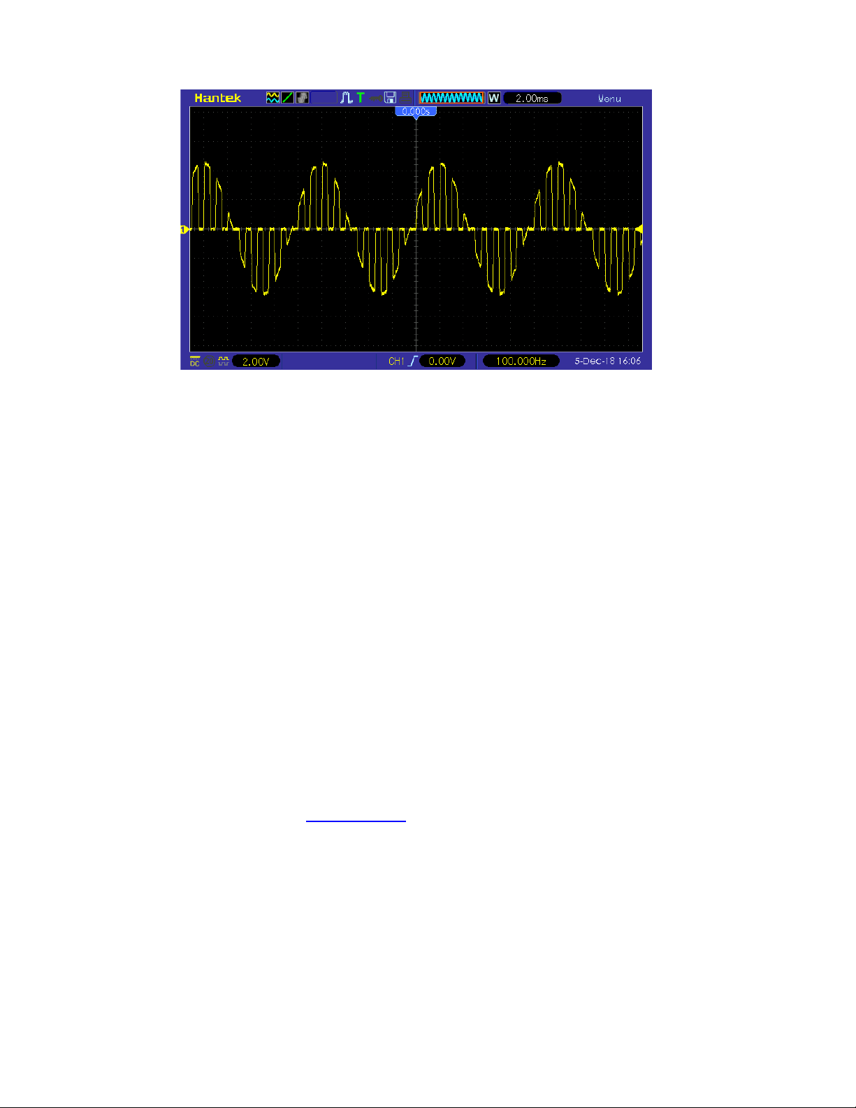
5.12.1 Select OSK Modulation
Press [Mod] >Type > OSKsoftkey to enable OSK function.
When Mod is enabled, Sweep or Burst will be disabled automatically.
After OSK is enabled, the instrument will generate OSK waveform with the currently specified
carrier and modulating waveforms. To avoid multiple waveform changes, enable modulation
after configuring the other modulation parameters.
5.12.2 Carrier Waveform Shape
OSK carrier waveform can only be sine waveform. Press [Wave]> Sine softkeyon the front panel
to select.
5.12.3 Carrier WaveformFrequency
For different carrier waveforms, the settable range of carrier frequency is different. Please refer to
"Frequency Characteristics" in "
Specifications".The default value is 1kHz.
Press [Setting] > Frequency softkey on the front panel, and then use the numeric keypad or
direction keys and knob to input the desired frequency value.
5.12.4 Modulation Source
Press [Mod] > Source softkey to select Internal (default) or External as the modulation source.
Internal Source
When internal modulation source is selected, the modulating waveform is set as a Square with
50% duty cycle, and the intermittence time and oscillate time of the output signal is determined by
the OSK "Rate".
User Manual 51

External Source
When external modulation source is selected, the signal generator receives the external
modulation signal from the [FSK/Trig/Sync/Extmod] connector on the rear panel.
5.12.5 OSK Rate
When internal modulation source is selected, press [Mod] > Rate softkey to set.
Use the numeric keypad or direction keys and knob to input the desired rate value.
The rate range is from 2mHz to 1MHz and the default is 100Hz.
Note: This menu will be grayed out and disabled when the external modulation source is selected.
5.12.6 Oscillate Time
Oscillate time is the oscillation period of internal crystal oscillator. The settable range of the
oscillate time is related to the OSK rate currently selected. Press [Mod] >OscTimesoftkey and
use the numeric keypad or direction keys and knob to input the desired time. The default range is
from 8ns to 4.99975ms.
5.13 PWM Modulation
A modulated waveform consists of a carrier waveform and a modulating waveform. In PWM, the
pulse width of the carrier waveform varies with the voltage level of the modulating waveform.
5.13.1 Select PWM Modulation
PWM is only available for the Square waveform.
Press [Wave] > Squaresoftkey, and then press [Mod] >Type >PWMsoftkey to enable the PWM
function.
If the Square function has not been selected as carrier waveform, PWM in [Mod] >Type
menu is unavailable.
When Mod is enabled, Sweep or Burst will be automatically disabled (if enabled currently).
After PWM is enabled, the instrument will generate PWM waveform with the currently
specified carrier and modulating waveforms.
5.13.2 Carrier Waveform Shape
PWM is only available for the Square waveform. Press [Wave]>Square.
User Manual 52

5.13.3 Carrier Waveform Duty
Press [Wave] > Squaresoftkey to select square as carrier waveform. Press
[Setting] >Dutysoftkey, then input the required value through the numeric keypad or knob.
5.13.4 Modulation Source
Press [Mod] > Signal Source softkey to select Internal, External or Another Channel as the
modulation source.
Internal Source
When internal modulation source is selected, press Shape softkey to select Sine, Square, Ramp,
Noise or Arb as the modulation source. The default is Sine.
Sine
Square: 50% duty cycle
Ramp: 50% symmetry.
Noise
Arb: Sinc, Exp Fall, Haver Sine, Lorentz, Gause, Dual Tone, ECG.
Note: Noise can be used as modulating waveform but cannot be used as carrier waveform.
External Source
When external modulation source is selected, the Frequency and Shape menu in the modulation
menu is grayed out and disabled. The instrument receives the external modulation signal from the
[FSK/Trig/Sync/Extmod] connector on the rear panel. The Duty Deviation is controlled by ±4V
signal level on this connector.
Other Channels
CH1 and CH2 can be used as modulation sources reciprocally. When CH1 is used as the
modulated wave, CH2 can be used as the modulation source. And vice versa.
When selecting another channel as the modulation source, please turn on the output of that
channel.
5.13.5 Modulation Frequency
When internal modulation source is selected, press [Mod] > Frequency softkey to set the
frequency of the modulating waveform.
Use the numeric keypad or direction keys and knob to enter the desired frequency value.
The modulating waveform frequency range is 2mHz to 1MHz, and the default value is 100Hz.
Note: This menu will be grayed out and disabled when other modulation sources except the
internal modulation source is selected.
User Manual 53

5.13.6 Duty Deviation
Press[Mod]>deviationsoftkey and input the desired value using the numeric keypad or direction
keys and knob.
Duty deviation represents the variation (in %) of the modulated waveform Duty relative to the
original pulse Duty.
Duty deviation range: 0.1% to 49.9%.
The Duty deviation cannot exceed the current pulse Duty.
Duty deviation is limited by the minimum Duty and current edge time setting.
When external modulation source is select, the Duty deviation is controlled by the ±4V signal level
on the [FSK/Trig/Sync/Extmod] connector on the rear panel.
User Manual 54

Chapter 6 Sweep
In sweep mode, the instrument outputs the waveform that changes from the start frequency to the
stop frequency at a specified sweep rate.HDG3000B(C) supports linear sweep mode.
Users can configure the instrument to output one sweep from start frequency to stop frequency by
applying an external or manual trigger. The instrument can sweep sine, square, pulse, ramp,
Harmonic or arbitrary waveforms (expect DC).
Select Sweep
Start Frequency and Stop Frequency
Center Frequency and Frequency Span
Linear Sweep
Sweep Time
Return Time
Hold Time
Mark Frequency
Sweep Trigger Source
Trigger Output Edge
User Manual 55

6.1 Select Sweep
Press[Sweep] button on the front panel to enable the Sweep function (the backlight of the key
goes on), and Mod or Burst function will be automatically disabled (if currently enabled).
To avoid multiple waveform changes, enable the sweep mode after configuring the other
parameters (as waveforms and amplitudes of basic waves).
Press [Sweep] button again to close sweep mode.
6.2 Start Frequency and Stop Frequency
The generator sweeps from the start frequency to the stop frequency and then returns back to the
start frequency.
Start Frequency < Stop Frequency: the generator sweeps from low frequency to high
frequency.
Start Frequency > Stop Frequency: the generator sweeps from high frequency to low
frequency.
Start Frequency = Stop Frequency: the generator outputs with a fixed frequency.
When [Sweep] is enabled,pressStart Frequency/Center Frequencysoftkey to highlight the
"Start Frequency".The "StopFrequency" in the Stop Frequency/Frequency Spansoftkey is
also highlighted.Use the numeric keyboard or direction keys and knob to input the desired
frequencies. By default, the start frequency is 100Hz and the stop frequency is 1KHz.Different
sweep waveform corresponds to different start frequency and stop frequency range.For frequency
parameters of different waveforms, please refer to "Frequency Characteristics" in
"
Specifications".
After modifying the frequency, the generator will restart to output the frequency sweep signalwith
the specified frequency.
6.3 Center Frequency and Frequency Span
Userscan also set the sweep frequency boundaries of the sweep using a center frequency and
frequency span.
Center Frequency = (|Start Frequency + Stop Frequency|) / 2
Frequency Span = Stop Frequency – Start Frequency
When [Sweep] is enabled,pressStart Frequency/Center Frequencysoftkey to highlight "Center
Frequency".The "Frequency Span" in the StopFrequency/Frequency Spansoftkey is also
highlighted.Use the numeric keyboard or direction keys and knob to enter the desired frequency
values. By default, the center frequency is 550Hz and the frequency span is 900Hz.Different
sweep waveform corresponds to different center frequency and frequency span range and center
frequency and frequency span are inter-related.
User Manual 56

Define the minimum frequency of the waveform currently selected as Fmin, the maximum
frequency as Fmax and Fm = (Fmin+Fmax)/2.
The range of center frequency is from Fmin to Fmax.For frequency parameters of different
waveforms, please refer to "Frequency Characteristics" in "
Specifications".
The range of the frequency span is influenced by the center frequency:
Center frequency <Fm: frequency span range is ±2 × (center frequency - Fmin);
Center frequency ≥Fm: frequency span range is ±2 × (Fmax- center frequency).
Take sine as an example. Fmin is 1μHz, Fmax is 160MHz and Fm is about 80MHz.
If the center frequency is 550Hz, the range of the frequency span is:
±2 × (550Hz – 1μHz) = ±1.099999998kHz;
if the center frequency is 155MHz, the range of the frequency span range is:
±2 × (160MHz – 155MHz) = ±10MHz.
After modifying the frequency, the generator will restart to output the frequency sweep signal with
the specified frequency.
Note: In large-scale sweep, the amplitude characteristic of the output signal might change.
6.4 Linear Sweep
HDG3000B(C) provides linear sweep type.
The output frequency of the instrument varies linearly in the way of "several Hertz per second".
The variation is controlled by "Start Frequency", "Stop Frequency" and "Sweep Time".
6.5 Sweep Time
Sweep time specifies the time required to sweep from the start frequency to the stop frequency.
When [Sweep] is enabled,pressSweep Timesoftkeyand use the numeric keyboard or knob to
change the sweep time.
The default value is 1s and the settable range is from 1ms to 50Ks.
6.6 Return Time
Return time specifies the number of seconds to return from the stop frequency to the start
frequency.
When [Sweep] is enabled, press the Return Time softkeyand use the numeric keyboard or knob
to change the return time.
The default value is 1s and the settable range is from 1ms to 50Ks.
User Manual 57

6.7 Hold Time
The hold time specifies how long time the waveform stays at the stop frequency.
When [Sweep] is enabled, press the Hold Time softkey and use the numeric keyboard or knob to
change the hold time.
The default value is 1s and the settable range is from 1ms to 50Ks.
6.8 Mark Frequency
When the output signalfrequency is less than the specified mark frequency, there will output the
low level signal from the[FSK/Trig/Sync/Extmod] connector on the rear panel.When the output
signal frequency is at or greater than the specified mark frequency, the signal outputson the
[FSK/Trig/Sync/Extmod] connector will change from low level to high level.
When [Sweep] is enabled,pressMarkFrequencysoftkeyand use the numeric keyboard or the
direction keys and knob to modify the mark frequency.The default value is 500Hz and the settable
range is limited by the "Start Frequency" and "Stop Frequency".
6.9 Sweep Trigger Source
The sweep trigger source could be internal, external or manual. The generator will generate a
sweep output when a trigger signal is received and then wait for the next trigger signal.
When [Sweep] is enabled,pressTrigger Sourcesoftkey to select Internal, External or
Manual.The default is internal.
Internal: The generator outputs continuous sweep waveformat a rate determined by the total
of the specified sweep time, return time and hold time.
External: The signal generator receives the trigger signal from the [FSK/Trig/Sync/Extmod]
connector on the rear panel.A sweep will be generated once the connector gets a TTL pulse
with specified polarity. To set the TTL pulse polarity, press Polarityto select "Positive" or
"Negative". The default is "Positive".
Manual: A sweep will be generated from the corresponding channel once you press [Trigger]
at the front panel.
6.10 Trigger Output Edge
In sweep mode, when "Internal" or "Manual" trigger source is selected, the generator will output a
TTL compatible signal with specified edge from the[FSK/Trig/Sync/Extmod] connector on the
rear panel.
Internal and Manual Trigger: The generator outputs a Pulse waveform from
the[FSK/Trig/Sync/Extmod] connector on the rear panelat the beginning of the Sweep.The
trigger period depends on the specified frequency sweep time, return time, and hold time.When
the output signal frequency is less than the specified mark frequency, there will output the low
User Manual 58

levelsignal from the [FSK/Trig/Sync/Extmod] connector on the rear panel. When the output
signal frequency is at or greater than the specified mark frequency, the signal outputs on the
[FSK/Trig/Sync/Extmod] connector will change from low level to high level.
External Trigger: The [FSK/Trig/Sync/Extmod] connector is used as the input terminal of
external trigger signal and has no trigger output.
User Manual 59

Chapter 7 Burst
The HDG3000B(C) can output a waveform for a specified number of cycles, called a burst. It
supports control of burst output by internal, external or manual trigger source; supports three
kinds of burst types including N cycle, Infinite cycle and Gated. Burst is allowed with sine, square,
ramp, pulse, Harmonic, noise (allowed only in gated burst mode) or arbitrary waveforms (except
DC).
Select Burst
Burst Type
Burst Count
Burst Period
Burst Phase
Trigger Source
Gate Polarity
Trigger Output Edge
User Manual 60
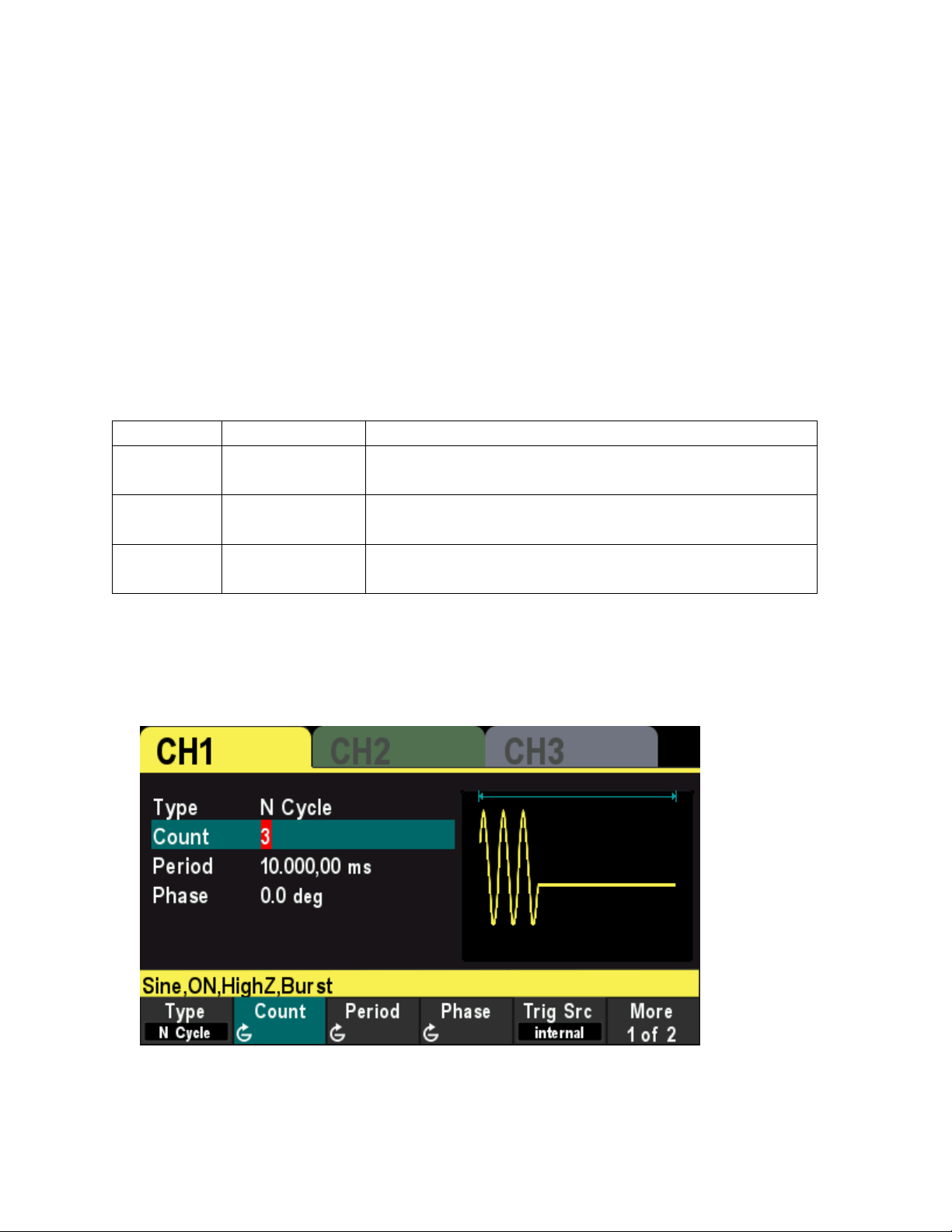
7.1 SelectBurst
Press[Burst] button on the front panel to enable Burst function (the backlight of the key goes
on),and Mod or Sweep function will be automatically disabled (if currently enabled).
To avoid multiple waveform changes, enable burst mode after configuring other parameters.
7.2 Burst Type
This instrument could output three types of bursts, including N Cycle, Infinite Cycle and Gate.
The default is N Cycle.
Burst Type
Trigger Source
Carrier Waveform
N Cycle Internal/External/
Manual
Sine/Square/Ramp/Pulse/Harmonic/Arbitrary waveform
(except DC)
Infinite External/Manual Sine/Square/Ramp/Pulse/Harmonic/Arbitrary waveform
(except DC)
Gated Ext Sine/Square/Ramp/Pulse/Noise/Harmonic/Arbitrary
waveform (except DC)
N Cycle Burst
In N Cycle mode, the generator will output waveform with specified number of cycles after
receiving trigger signal.
Press [Burst] >Type softkey to select“N Cycle”.
For N Cycle mode, the trigger source includes "Internal", "External" or "Manual". Besides, users
can set the "Phase", "Count", "Burst Period" (internal trigger), "Trigger Slope" (external trigger)
and "Trigger" (manual trigger).
Infinite CycleBurst
In Infinite Cycle mode, the cycle number of the waveform is set as an infinite value. The generator
User Manual 61
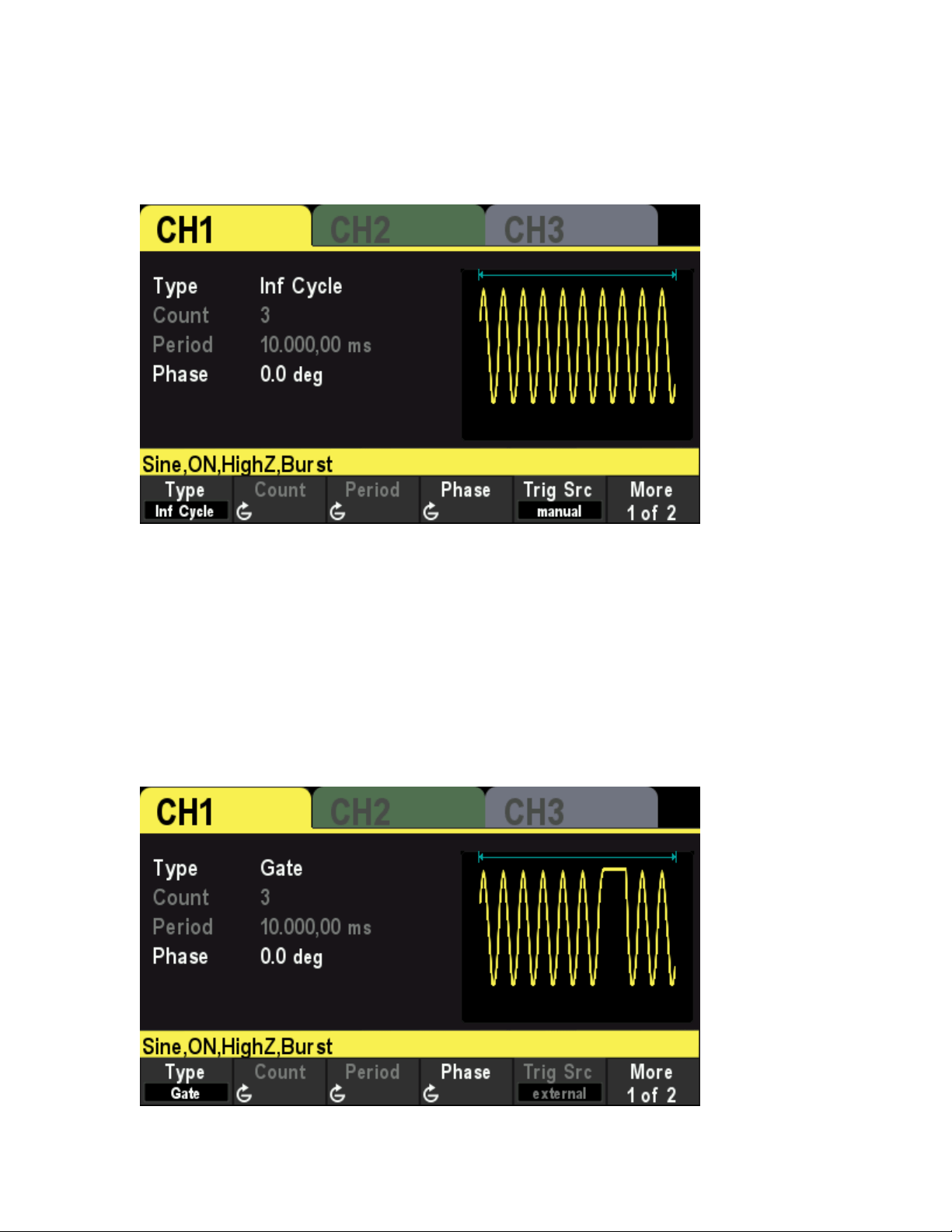
outputs a continuous waveform after receiving trigger signal.
Press [Burst] >Type softkey to select “Inf Cycle”.A schematic diagram of infinite cycle pulse will
be displayed on the screen.
For Infinite Cycle mode, the trigger source includes "Internal", "External" or "Manual". Besides,
users can set the "Phase", "Count" and "Trigger Slope" (external trigger) and "Trigger" (manual
trigger).
GatedBurst
In Gated Mode, the generator controls the waveform output according to the external signal level
from the[FSK/Trig/Sync/Extmod] connector on the rear panel.
Press[Burst] >Type softkey to select“Gate”and then press Polarity to set the gated polarity as
"Positive" (or "Negative"). The generator outputs burst waveform only when the gated signal is
"Positive" (or "Negative").
When the gated signal is "True", the generator outputs a continuous waveform; when the gated
signal is "False", the generator completes the current period, and then stops and holds on the
voltage level corresponding to the initial burst phase of the selected waveform. For Noise
User Manual 62

waveform, the output will stop immediately once the gated signal becomes "False".
Gated Burst could only be triggered by External trigger source. In addition, users can set the
"Phase".
7.3 BurstCount
Burst count is the number of carrier waveforms in one burst period. It is only available forN
CycleBurst mode (internal, external, or manually trigger sources).
For internal trigger source, Burst period ≥ 1μs + Carrier Waveform Period × Burst Count.
Press[Burst] > Type softkey to select“N Cycle”.The “Count” parameter is highlighted and is
editable.And use the numeric keypad or direction keys and the knob to input the desired
count.The default is 1 and the settable range is 1 to 2000 000 000.
This menu will be grayed out and disabled when the burst type is set to Infinite cycle or Gated.
7.4 BurstPeriod
Burst period is the time from the start of one burst to the start of next burst. It is only available for
N Cycle burst in internal trigger.Thedefault is 10 ms.
Burst period ≥ 1μs + Carrier Waveform Period × Burst Count.
If the burst period is set to too small, the generator will increase this period automatically to
allow the output of the specified number of cycles.
Press[Burst] >Typesoftkey to select N Cycle.PressTrig Srcsoftkeyand select Internal,
thenpressPeriodsoftkey, and use the numeric keypad or direction keys and the knob to input the
desired period.The default value is 10ms and the settable range is 2μs to 500s.
This menu will be grayed out and disabled when the burst type is set to Infinite cycle or Gated.
7.5 BurstPhase
Burst phase is defined as the phase of the start point of the burst.
WhenBurst is enabled, pressPhasesoftkey and use the numeric keypad or direction keys and the
knob to input the desired phase. The default value is 0° and the settable range is 0° to 360°.
For Sine, Square, Ramp and Pulse, 0° is the point where the waveform passes through 0V
(or DC offset value) positively.
For arbitrary waveform, 0° is the first point of the waveform.
For Noise, Start Phase is unavailable.
7.6 Trigger Source
Burst trigger source could be internal, external or manual. The generator will generate a burst
output when a trigger signal is received and then wait for the next trigger
When Burst is enabled, press Trig Src softkey to select "Internal", "External" or "Manual". The
User Manual 63

default setting is "Internal".
Internal Trigger
When internal trigger is selected, the generator can only output N cycle burst and the burst
frequency is determined by the "Burst Period".
External Trigger
When external trigger is selected, the generator can output N cycle, infinite or gated burst. The
generator receives the trigger signal from the[FSK/Trig/Sync/Extmod] connector on the rear
panel. A burst will be generated once the connector receives a TTL pulse with specified slope or
polarity.
To set the extrenal trigger slope, press Slope softkey to select "Rising" or "Falling" and the default
is "Rising".
Manual trigger
When manual trigger is selected, the generator can output N cycle or infinite burst. A burst will be
generated from the corresponding channel (if currently turned on) Once the Trigger button at the
front panel is pressed. If the corresponding channel is not turned on, the trigger will be ignored.
7.7 GatePolarity
Gate polarity is only available in gated burst mode. The generator will output burst when the gated
signalfrom the[FSK/Trig/Sync/Extmod] connector on the rear panel is "High Level" or "Low
Level".
When Burst is enabled, press Type softkey to select "Gate" and press Polarity softkeyto select
"Positive" or "Negative". The default is "Positive".
7.8 Trigger Output Edge
In burst mode, when the trigger source is "Internal" or "Manual", the generator would output a
TTL-compatible signal with specified edge from the[FSK/Trig/Sync/Extmod] connector on the
rear panel.
Internal trigger: The generator outputs a square waveform with variable duty cycle (related
to the carrier period and number of cycles) from the [FSK/Trig/Sync/Extmod] connector at
the start of the burst.
Manual trigger: The generator outputs a pulse from the [FSK/Trig/Sync/Extmod] connector
at the start of the burst.
External Trigger: The [FSK/Trig/Sync/Extmod] connector is used as the input terminal of
external trigger signal and has no trigger output.
User Manual 64
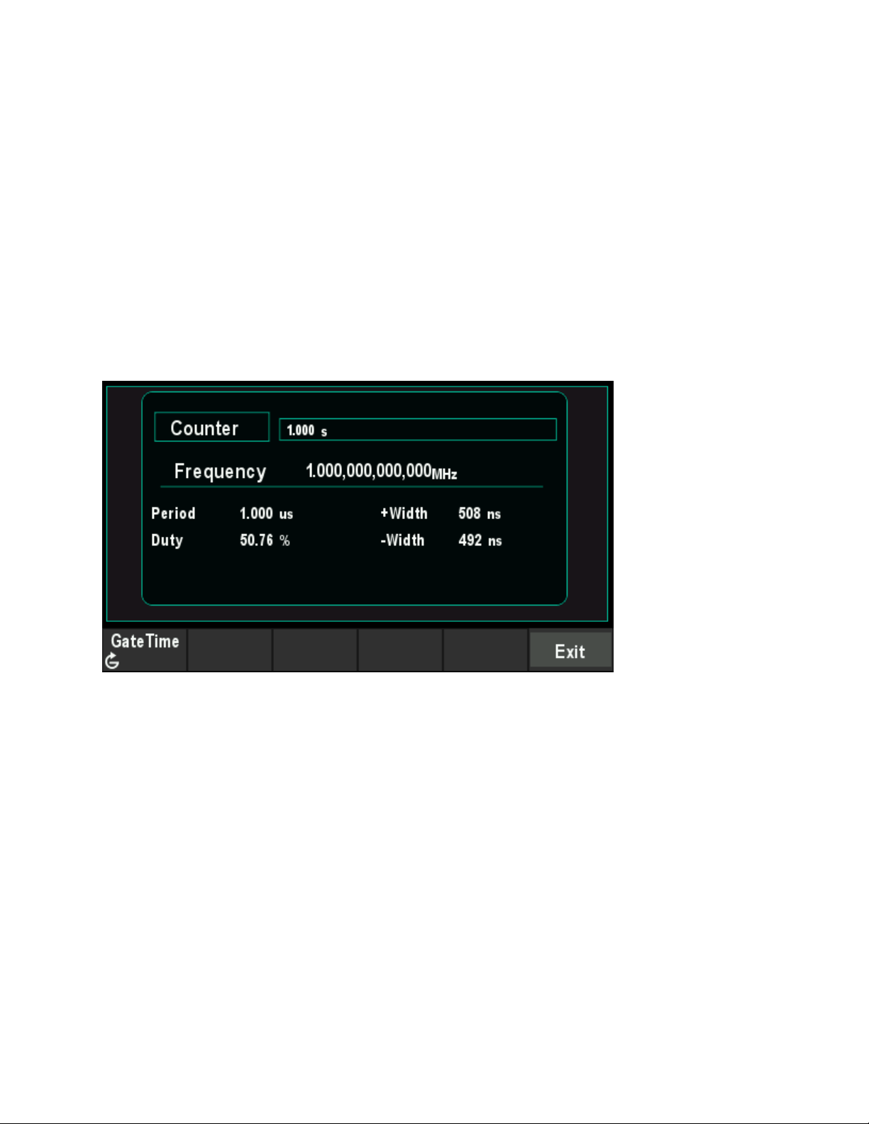
Chapter 8 Counter
The generator provides a counter which can measure various parameters (such as frequency,
period, duty cycle, positive pulse width and negative pulse width) of external input signal.
Press[Utility] >Countersoftkey on the front panel to enablecounter function.Input the singal to the
Counter connector on the rear panel measure.
Press Exit softkey or any other key toexit the counter.
PressGate Time softkey and use the direction keys and the knob to modify the current value.
The default value is 1s and the settable range is 10ms to 16s.
User Manual 65
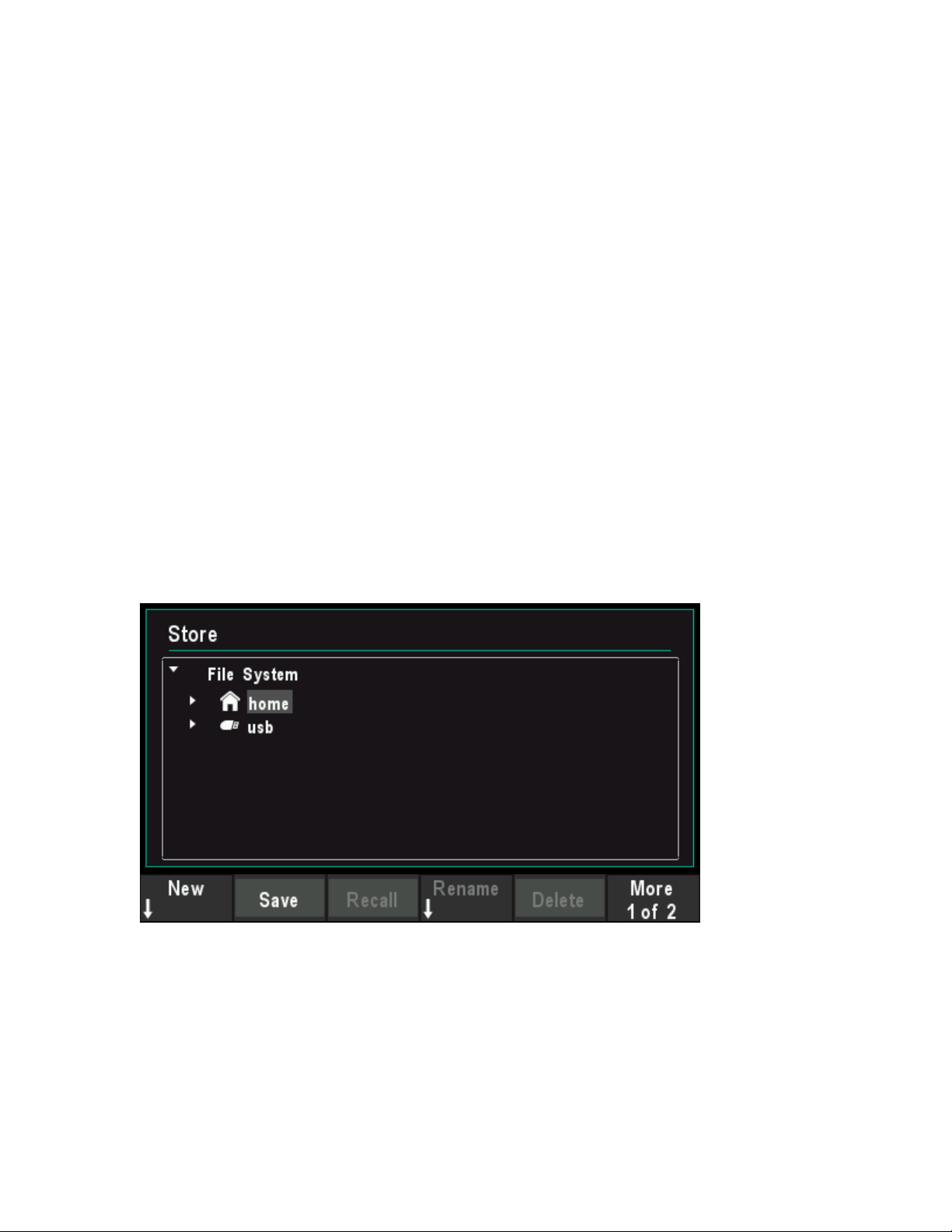
Chapter 9 Store
The instrument allows the user to store the current settings state of the instrument in internal or
external storage and recall it when needed.
9.1 Store System
The instrument provides an internal memory (home disk) and an external memory (USB disk).
Home disk: Users can save the instrument settings state to this disk in.pho format. And the file
also can be recalled.
USB disk: Available when the instrument detects external storage (front USB port). Users can
save the instrument settings state to external storagein.pho format. The state files .pho and
arbitrary waveform files .hwf in the external memory can be recalled.
The instrument settings state file includes waveform basic parameters,Mod/Sweep/Burst
parameters and counter parameters.
Press [Utility] >Store softkey to open the store interface, as shown in the figure below.
Note: The instrument can only identify filenames consist of English letters, number and
underscore. If other characters are used to name the file or folder, the name might be displayed in
the store and recall interface abnormally.
9.2 File Operation
Press [Utility] > Store softkey to enter File System, users can perform a series of operations on
files or directories including New, Save, Recall, Rename, Delete, and Refresh.
User Manual 66

New File
In Store interface, rotate the knob to select home disk or usb disk, and then press New softkey to
enter the filename editing interface, as shown in the figure below.
1. Press Type softkey to select "File".
File: Create a new state file.
Directory: Create a new directory.
2. Press Switch Focus softkey and select Name or Keypad.
Name: Put the cursor in the Filename Input Area. Use direction keys to move the cursor
position and specify the location of the modified character.
Keypad: Put the cursor in the Virtual Keyboard. Rotate the knob to move the cursor position
and press down the knob to input the character. In the virtual keyboard, rotate the knob to
select Capsand press down to switch between uppercase and lowercase; rotate the knob to
select Shift and press down to switch some symbols.
3. Press Backspace softkey to remove the characters in front of the cursor one by one.
4. Press Delete softkey to delete all the characters in the Filename Input Area.
5. After entering the file name in the Filename Input Area, press Save softkey to save the state
file.
6. PressReturn softkey to exit the New menu and return to the previous menu.
Save
Press Save softkey to automatically create a new state file and save it.
Recall
Press Recall softkey to recall the state file or arbitrary waveform file.
Filename Input Area
Virtual Soft Keyboard
User Manual 67
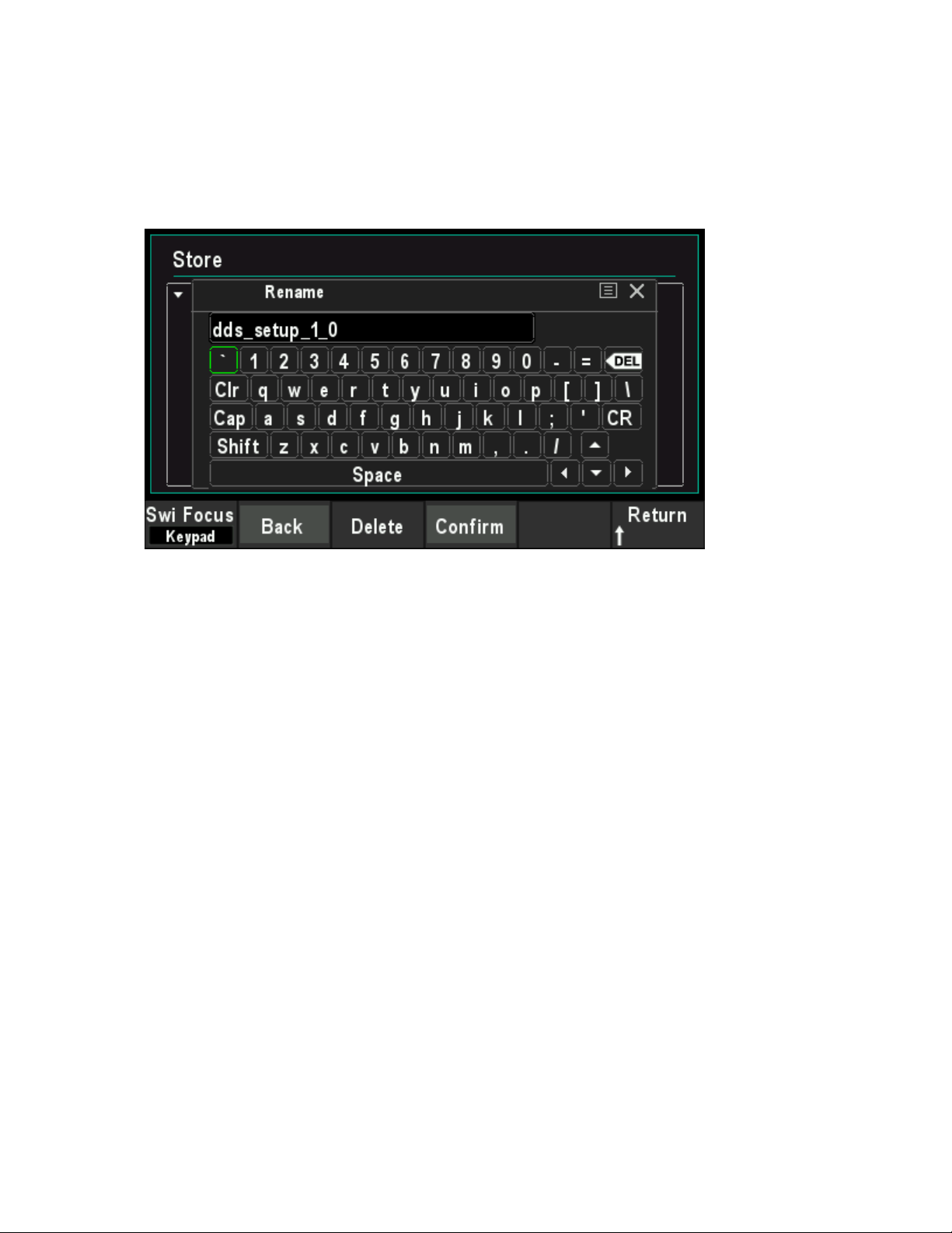
Rename
Use the knob to select the specified file or directory and press Rename softkey to rename. Refer
to the operation method of creating a new file. After the completion of the denominate, press
Confirm softkey to confirm the change.
Delete
Use the knob to select the specified file or directory and press Delete softkey to delete the
selected file or directory.
Refresh
Press Refrash softkey to refresh the file list.
User Manual 68

Chapter 10 Utility
The signal generator allows the user to configure channel parameters, configure remote
interfaces, and set system parameters.
Sync
Impedance Settings
System Settings
Firmware Update
User Manual 69

10.1 Sync
The synchronous signal is output from the [FSK/Trig/Sync/Extmod] connector on the rear panel.
The instrument could output the sync signals of basic waveforms (except Noise), arbitrary
waveforms (except DC), Harmonics, Sweep, Burst and Modulation from a single channel or two
channels at the same time.
The sync signal is a squarewaveform that is "high" in the first half of the cycle and "low" in the
second half.When sync signal is disabled, the output level at the
[FSK/Trig/Sync/Extmod]connector is logic low.
The amplitude of Sync signal is not adjustable andis fixed at TTL level.
Sync Signals of Various Waveforms
For Sine, Square, Ramp, and Pulse, the sync signal is a Square with 50% duty cycle.When
the first wave point is output, the synchronization signal is TTL high level.When the frequency
of the basic waveform is less than or equal to 30 MHz, the sync signal has the same
frequency as the basic waveform. When the frequency of the basic waveform is greater than
30 MHz, the frequency of the sync signal is (the basic waveform frequency ÷2
n
). Wherein, n
represents the frequency dividing coefficient, and it is 1 when the frequency of the basic
waveform is greater than 30 MHz and less than or equal to 60 MHz, and it is 2 when the
frequency of the basic waveform is greater than 60 MHz and less than or equal to 90 MHz.
For noise, there is no sync signal output.
For arbitrary waveform, the sync signal is a square with 50% duty cycle.When the first wave
point is output, the sync is TTL high level.The frequency of the sync signal is the frequency of
arbitrary waveform.
For harmonics, the sync signal is a square with 50% duty cycle.When the first waveform point
is output, the sync signal is TTL high level.The frequency of the sync signal is the frequency
of the basic wave.
For AM, DSB-AM, FM, PM and PWM modulation, when internal modulation source is
selected, the sync signal is a square with 50% duty cycle and takes modulating frequency as
reference.When the first waveform point is output, the sync signal is TTL high level. When
external modulation source is selected, there is no sync signal output.
For ASK, FSK, PSK, BPSK, QPSK, 3FSK, 4FSK, OSK modulation, the sync signal is a
square with 50% duty cycle and takes the modulating rate as reference. For ASK, FSK, PSK,
OSK modulation, when external modulation is selected, there is no sync signal output.
For Sweep, when the frequency of the sweep signal is less than the mark frequency, the sync
signal is a TTL low level.When the frequency of thesweep signal is at or greater than the
mark frequency, the sync signal is changed from TTL low level to TTL high level.
For N-cycle burst, when internal or manual are selected as the trigger source, the sync signal
is TTL high level at the start of the burst.At the end of the specified count of cycles, the sync
signal is TTL low level (it may not be zero intersection if the waveform has an associated
starting phase).For an infinite-cycle burst, when manual triggered is selected, the sync signal
is the same as that of the basic waveform.For all burst types, when external trigger is
User Manual 70
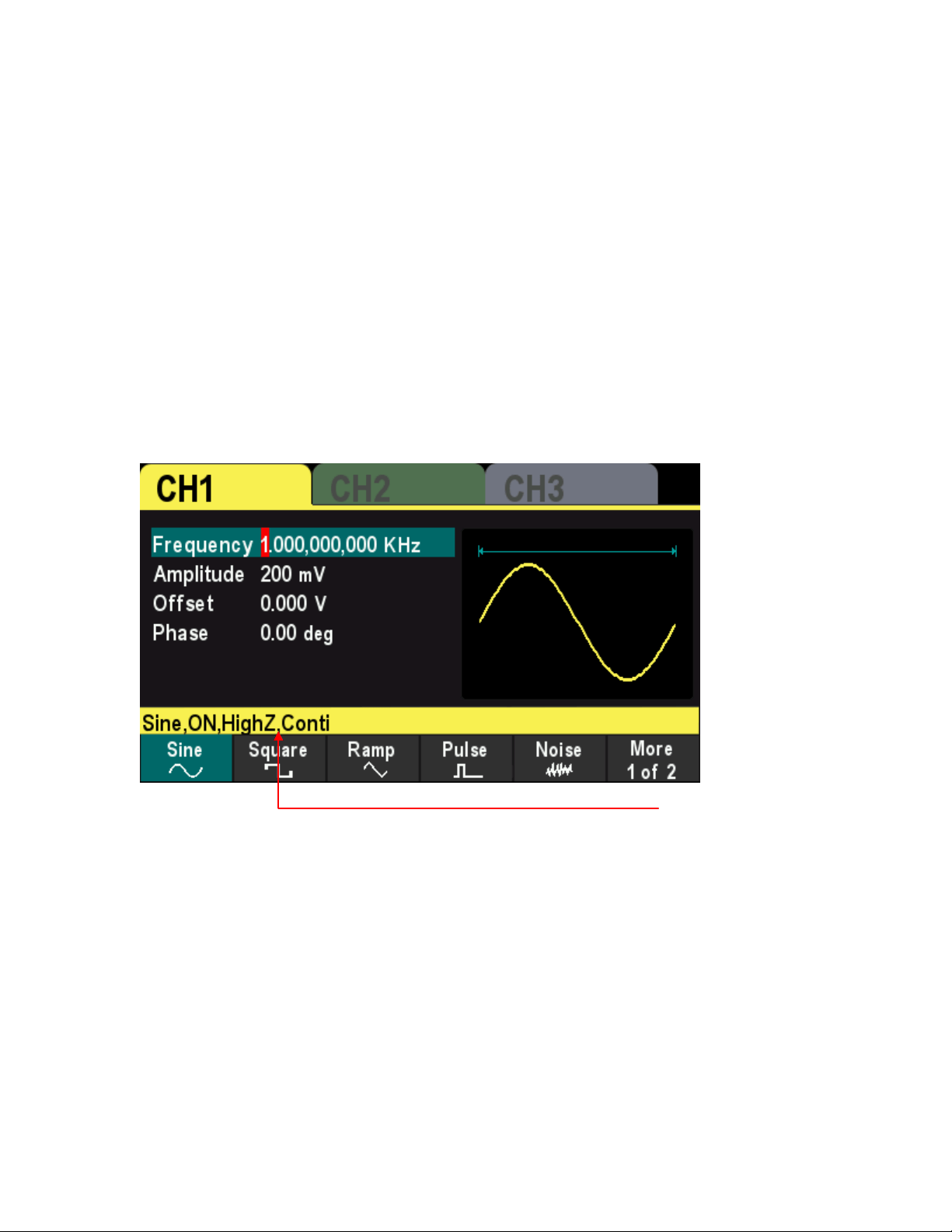
selected, there is no sync signal output.
10.2 Impedance Settings
The Impedance setting affectsthe output amplitude and DC offset voltage.For the front panel [1]
connector, the HDG3000B(C) has a fixed series output impedance of 50Ω.If the actual load is
different from the specified value, then the displayed voltage level will not match the voltage level
of the components under test. To ensure the correct voltage level, ensure that the load impedance
setting must match the actual load.
Press [Utility] > CH1 Set>Impedancesoftkeyto choose HighZor 50Ω.The default setting is HighZ.
Impedance settings will be displayed on the screen.As shown in the figure below, the impedance
of CH1 is set to "HighZ".
The generator will adjust the output amplitude and offset voltage automatically once the
impedance setting is changed. For example, the current amplitude is 5Vpp and the output
impedance is 50Ω. At this point, change the output impedance to HighZ and the amplitude
displayed on the screen will double to 10Vpp. And the current amplitude is 5Vpp and the output
impedance is HighZ. At this point, change the impedance to 50Ω, the amplitude will reduce to half
of the previous value (2.5Vpp).
Note: Only the displayed values change with the parameter and the real output from the generator
does not change.
Impedance setting
User Manual 71

10.3 System Settings
10.3.1 Language
The signal generator supports Chinese and English menu, and provides corresponding help
information, prompt information and interface display.
Press [Utility] > Languagesoftkey to select the desired language.When "Chinese" or "English" is
selected, the menu, help message, prompt message, and interface are displayed in Chinese or
English, respectively.
The language is not changed when the [P] key is pressed to restore the default settings.
10.3.2 Clock Source
The instrument provides an internal 10MHz clock source and can receive the external clock
source from the 10MHz In/Out connector at the real panel. It can also output the internal clock
source from the 10MHz In/Out connector for other devices.
Press Utility >Clock Sourcesoftkey to select "Internal" or "External". The default is "Internal". If
"External" is selected, the instrument will detect whether a valid external clock signal is input from
the 10MHz In/Out connector at the real panel. If no valid clock source is detected, the prompt
message "No valid 10MHz External Clock is detected" would be displayed and the clock source
would be switched to "Internal".
Users can also synchronize two or more instruments by setting the clock source. When two
instruments are synchronized, the SYNC of phase cannot be used. The SYNC of phase can only
be used to adjust the phase relation between two output channels of the same instrument and
cannot be used to change the phase relation between the output channels of two instruments.
Users can change the phase relation between two instruments by change the "Start Phase" of
each channel.
Sync methods for two or more instruments:
Synchronization between two instruments:
Connect the 10MHz In/Out connector of Generator A (set the clock source to "Internal") to
the 10MHz In/Out connector of Generator B (set the clock source to "External") and set the
output frequencies of the two instruments as a same value to realize the synchronization
between the two instruments.
Synchronization among multi-instruments:
Divide the 10MHz clock source of a generator (set the clock source to "Internal") into multiple
paths; then, connect them to the 10MHz In/Out connectors of the other generators (set the
clock source to "External) respectively. Finally, set the output frequencies of all the
generators as a same value to realize the synchronization among multi-instruments.
User Manual 72

10.3.3 Power On Settings
Set the configuration to be used when the instrument is powered on the next time to Default, Last
or Output off. The default setting is "Default".
Default: Denote the factory default settings except some parameters (such as: Language).
Last: Include all the system parameters and output configuration, except clock source.
Output off: The last setting will be used and all output will be closed.
Press [Utility]>Startup softkey to select the desired configuration type.
When [P] keyis pressed to restore the default settings, this setting will not be affected.
10.3.4 Intensity
Press[Utility] >Intensitysoftkey and use the direction keys and the knob to change the backlight
intensity of the screen.
The ranges from 1% to 100%.
10.3.5 System Information
Press[Utility] >System Informationsoftkey to view the information of the device (such as model,
serial number, version number, etc.).
10.3.6 Unit
Press[Utility] >Unitsoftkey to select units of waveform parameters.
Frequency/Period - Select the period or frequency as the waveform parameter that can be set.
Amplitude/high level - Select the amplitude or high level as the waveform parameter that can be
set.
Offset/Low Level - Select the offset or low level as the waveform parameter that can be set.
Pulse width/duty cycle - Select the pulse width or duty cycle as the pulse parameters that can be
set.
10.3.7 Save Picture
Users can store the content displayed on the screen in an external storage device in the form of
pictures.
First, please connect the USB stick (FAT32 format, storage space is less than or equal to 32G)
and insert the USB stick into the USB port on the front panel of the instrument.After successful
connection, the corresponding prompt message pops up on the screen.
User Manual 73

Then enter the interface that you need to save, andpress[Utility] button, the instrument completes
the screenshot and enters the Utility menu. At this time, the signal generator has cached the
screenshot inside the instrument.PressSavePicsoftkey, and the instrument will save the
screenshot to the USB stick.
Note: The screenshot cached is always the screen at the last time the [Utility]button was
pressed.
10.4FirmwareUpdate
Copy the firmware to a USB stick (FAT32 format, storage space is less than or equal to 32GB)
and insert the USB stick into the USB port on the front panel of the instrument.
Press[Utility] >Updatesoftkey, enter the file browser interface, use the knob to select the
firmware file, pressRecallsoftkey to specify the file, and then pressOKsoftkey to start the firmware
update.
User Manual 74

Chapter 11 Remote Control
The HDG3000B(C) can be controlled remotely through the following two mothods.
Use PC software
Users can use the PC software to send commands to remotely control the instrument. You can
download the software from our official website.
User-defined programming
Users can program and control the instrument by using the SCPI (Standard Commands for
Programmable Instruments) commands. For more information about the commands and
programming, refer to the SCPI protocol manual.
HDG3000B(C) can communicate with PC through USB.This chapter will give a detailed
introduction of how to use software to control HDG3000B(C) remotely through the real USB port.
Install Keysight IO libraries suite
Remote Control via USB
User Manual 75
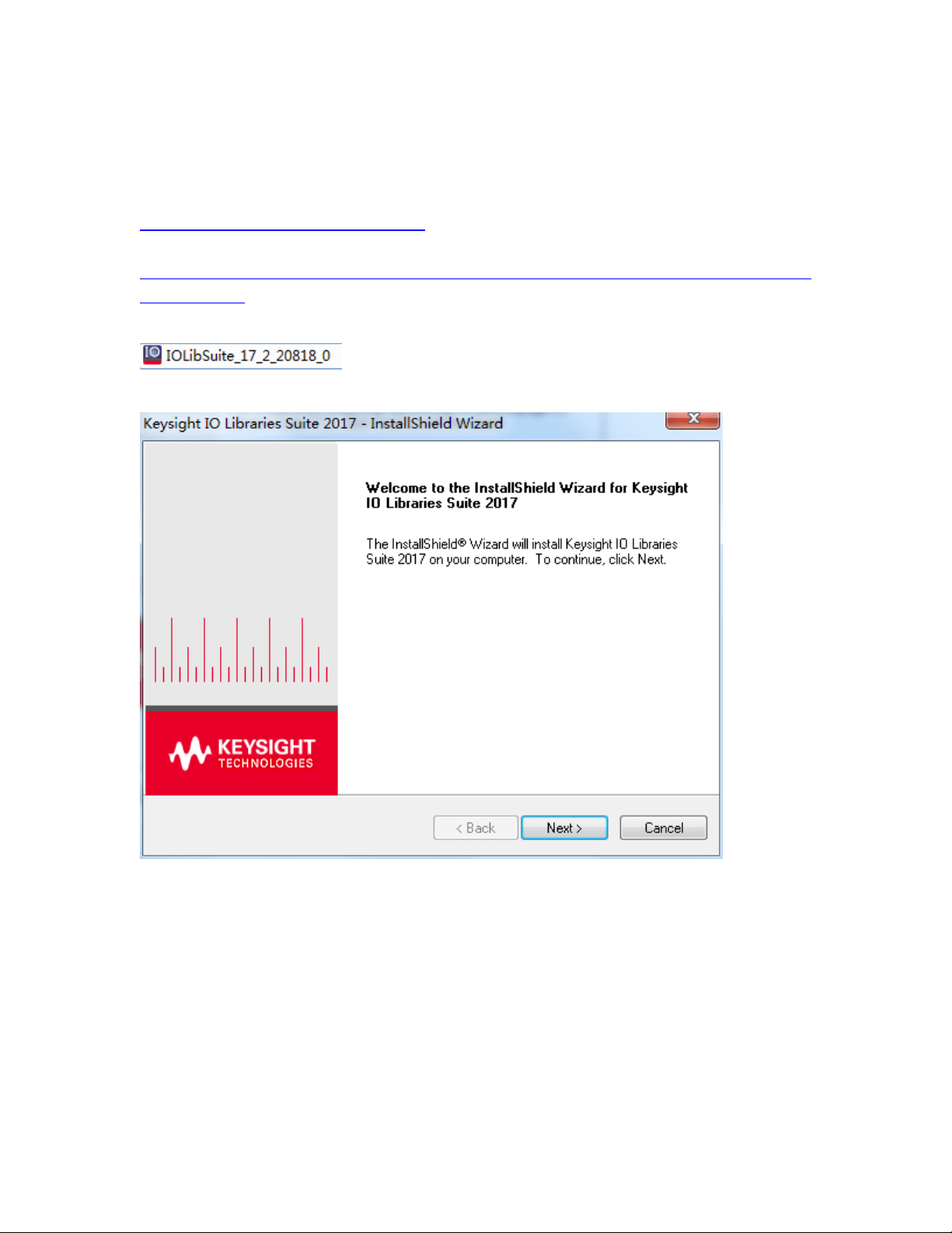
11.1 Install Keysight IO libraries suite
Users can download the application software package on the official website of Hantek:
http://hantek.com/products/detail/17187
Or click the following website to download latest one:
http://www.keysight.com/main/software.jspx?ckey=2175637&id=2175637&nid=-11143.0.00&l
c=eng&cc=GB
Double click the icon to start installing.
Click ‘Next’ to continue.
Read License Agreement and accept. Click ‘Next’ to continue.
User Manual 76
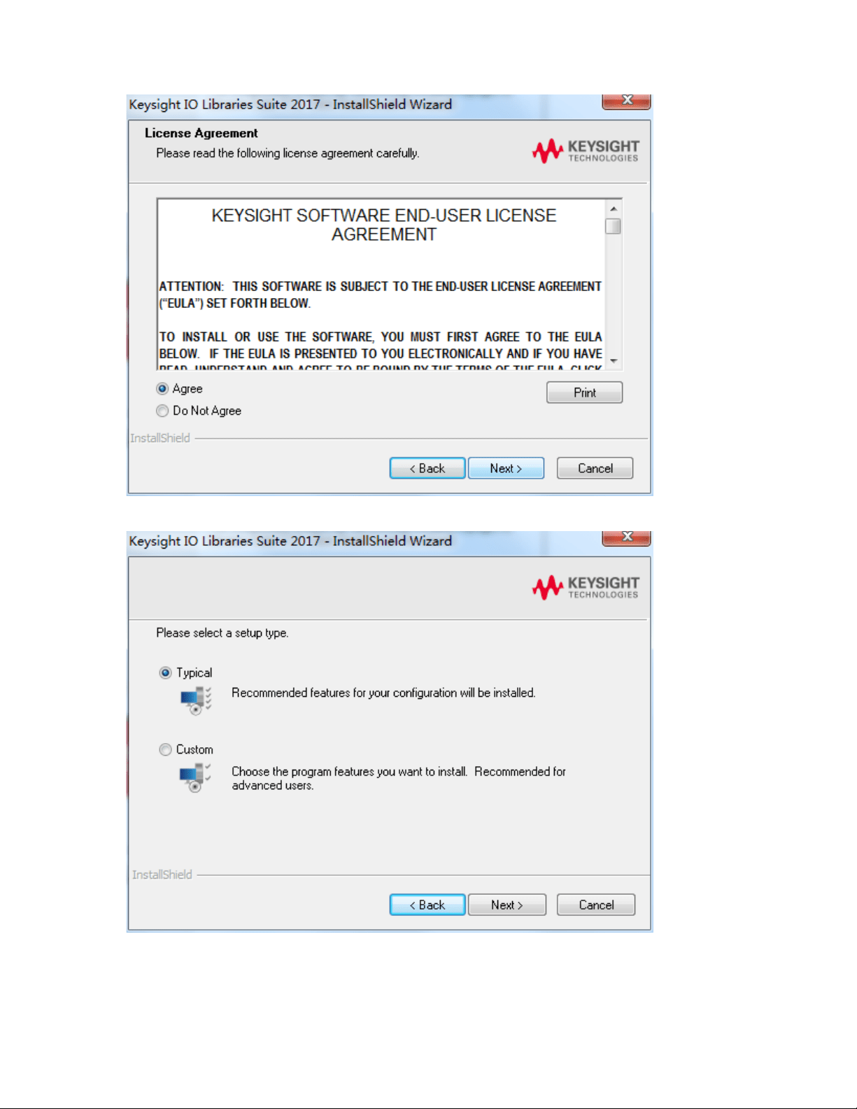
Select a Typical and click ‘Next’ to continue.
Or select a Custom and click ‘Next’ to continue.
User Manual 77
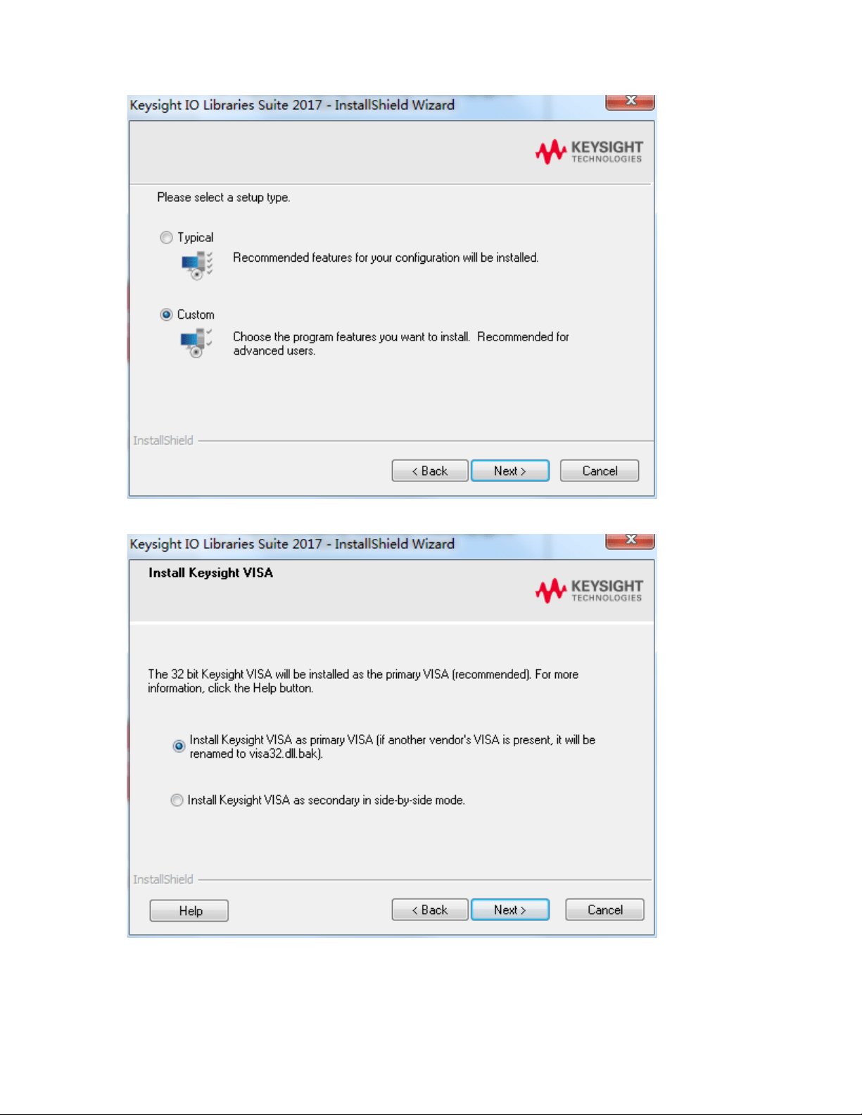
Select “Install Keysight VISA as primary VISA” and click ‘Next’ to continue.
Click ‘Install’ to start copying files.
User Manual 78
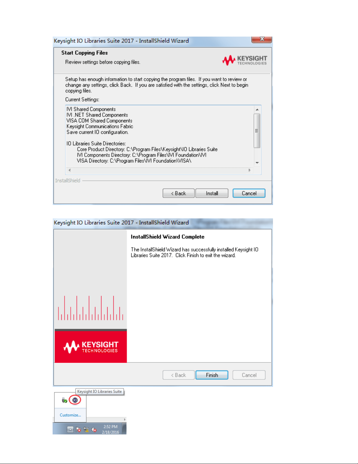
The installation is completed automatically. You will see the running IO program in the lower
right corner of the screen.
User Manual 79
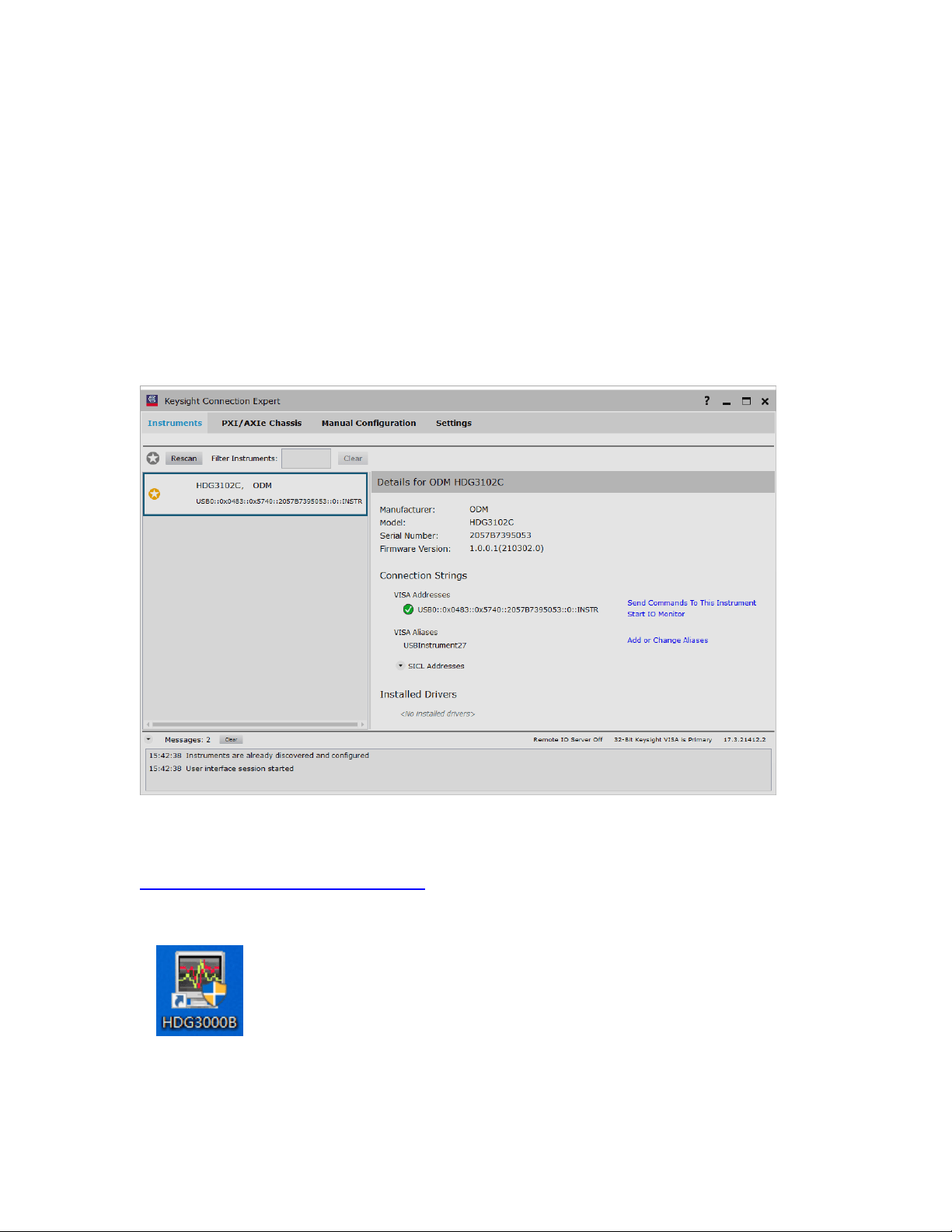
11.2 Remote Control via USB
1. Connect the device
Connect the instrument with your PC using a USB cable.
2. Search for device resource
Start up Keysight IO and the software will automatically search for the instrument resource
currently connected to the PC. You can also click Rescan to search for the resources.
3. View the device resource
The resource found will appear under the directory, and the model number and USB interface
information of the instrument will also be displayed.
For example, HDG3102C(USB0::0x0483::0x5740::************::0::INSTR)
4. Control the instrument remotely
1) Use PC software
Users can download the application software package on the official website of Hantek:
http://hantek.com/products/detail/17187
Double-click the Setup.exe file and install it according to the installation wizard.
After the installation is complete, the software icon will be displayed on the computer desktop.
Double click the software icon on the desktop after you finished the software setting and
equipment connecting. Then a user interface will be showed as follows:
User Manual 80
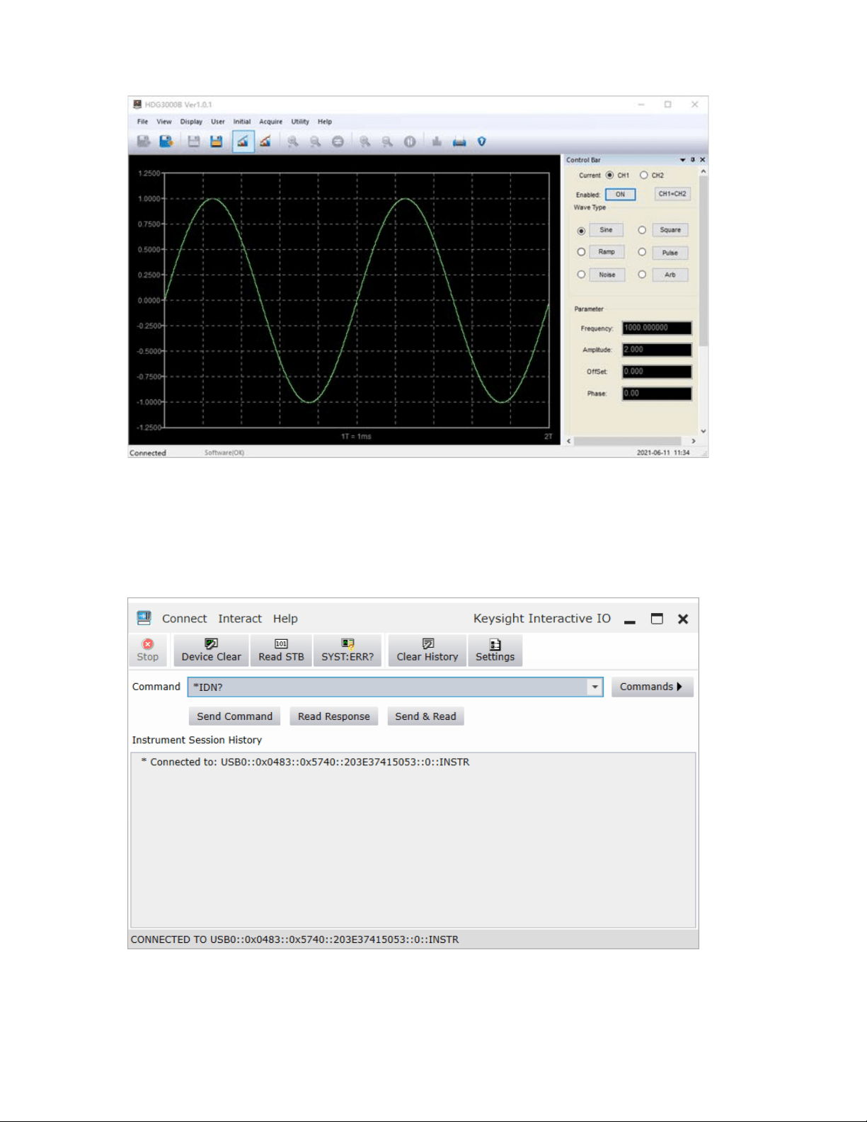
2) User-defined programming
Start up Keysight IO and the software will automatically search for the instrument resource
currently connected to the PC.
Click “Send Commands To This Instrument” to open Keysight interactive IO interface.You can
send commands and read data.
For more information about the commands and programming, refer to the SCPI protocol
manual.
User Manual 81

Appendix A Specifications
All technical specifications are suitable for HDG3000B(C) series signal generators.Unless
otherwise stated, all technical specifications are guaranteed upon the following two conditions.
The signal generator is in the calibration period.
The signal generator has operated continuously for more than 30 minutes at the specified
operating temperature (18℃ to 28℃).
All specifications used are guaranteed, except those marked "Typical".
Model
HDG3102B
HDG3082B
HDG3062B
HDG3042B
HDG3022B
HDG3012B
Channel
2
Memory Depth 2M
Maximum
Frequency
100MHz 80MHz 60MHz 40MHz 25MHz 15MHz
Sampling Rate
300MSa/s
Voltage
Resolution
16Bit
Waveforms
Standard
Waveforms
Sine, Square, Ramp, Pulse, Noise, Harmonic, DC
Arbitrary
Waveforms
More than 160 kinds, including Sinc, Exponential Rise, Exponential Fall,
ECG, Gauss, Haver Sine, Lorentz, Dual-Tone, etc.
Frequency Characteristics
Sine
1uHz~100MHz
1uHz~80MHz
1uHz~60MHz
1uHz~40MHz
1uHz~25MHz
1uHz~15MHz
Square
1uHz~15MHz
1uHz~15MHz
1uHz~15MHz
1uHz~15MHz
1uHz~15MHz
1uHz~15MHz
Pulse
1uHz~15MHz
1uHz~15MHz
1uHz~15MHz
1uHz~15MHz
1uHz~15MHz
1uHz~15MHz
Ramp
1uHz~2MHz
1uHz~2MHz
1uHz~2MHz
1uHz~2MHz
1uHz~2MHz
1uHz~2MHz
Harmonic
1uHz~50MHz 1uHz~40MHz 1uHz~30MHz 1uHz~20MHz
1uHz~10MHz
1uHz~5MHz
Noise (-3dB) 100 MHZ bandwidth
Arbitrary
1uHz~20MHz 1uHz~20MHz 1uHz~20MHz 1uHz~15MHz
1uHz~15MHz
1uHz~15MHz
Resolution
1uHz
Accuracy
±1ppm, 18 ~ 28 ℃
Square Characteristics
Rise/Fall time
Typical (1kHz, 1Vpp)
≤9ns
Overshoot
Typical (100kHz, 1Vpp)
≤5%
Duty Cycle
0.001%~99.999%;
Range varies with frequency
Non-symmetry 1% of the period + 4ns
User Manual 82

Ramp Characteristics
Linearity
≤ 1% of peak output (typical, 1kHz, 1Vpp, symmetry 100%)
Symmetry 0% ~ 100%
Pulse Characteristics
Period 67ns~1Ms 67ns~1Ms 67ns~1Ms 67ns~1Ms 67ns~1Ms
67ns~1Ms
Pulse
≥16ns
Duty Cycle
0.001%~99.999%;
Range varies with frequency
Rise/Fall time ≥9ns
Overshoot
Typical (1kHz, 1Vpp)
≤5%
Arbitrary Wavefrom Generator
Waveform
Length
2M
Vertical
Resolution
16 Bits
Sampling Rate
1uSa/s~ 75MSa /s, 1uSa /s resolution
Rise/Fall time ≥9ns
Overshoot
Typical (1Vpp)
≤5%
Harmonic Characteristics
Harmonic
order
≤16
Harmonic type
Even, Odd, All
The harmonic
amplitude
can be set for all harmonics
Harmonic
phase
can be set for all harmonics
Amplitude Characteristics (50Ω terminal)
Amplitude
Range
≤10MHz: 1mVpp ~ 10Vpp;
≤55MHz: 1mVpp ~ 5.5Vpp;
≤80MHz:1mVpp ~ 3.5Vpp;
≤100MHz:1mVpp ~ 2Vpp;
Accuracy
Typical (1kHz Sine, 0V offset, > 10mVpp)
±1% of setting value ± 5mVpp
Amplitude
flatness
(relative to
1kHz Sine,
3.5Vpp, 50Ω)
≤5MHz: ±0.1dB;
≤15MHz: ±0.2dB;
≤25MHz: ±0.3dB
≤40MHz: ±0.5dB
≤100MHz: ±1.0dB
User Manual 83

Unit
Vpp, mVpp, Vrms, dBm (50Ω terminal)
Resolution 1mVpp
Offset Characteristics (50Ω terminal)
Range ±5Vpkac+dc
Accuracy
±(1% of setting value + 5mV + 1% of amplitude)
Waveform Output
Impedance 50Ω
Modulation Characteristics
Modulation
Type
AM, DSB-AM, FM, PM, ASK, FSK, PSK, BPSK, QPSK, 3FSK, 4FSK, OSK,
PWM
AM
Carrier
Waveforms
Sine, Square, Ramp, Pluse, Harmonic, Arb. (except DC)
Modulation
Source
Internal, External, another channel
Modulation
Waveforms
Sine, Square, Ramp, Noise,
Sinc, Exp Fall, Haver Sine, Lorentz, Gause, Dual
Ton e, EC G
Modulation
Frequency
2mHz~1MHz
Modulation
Depth
0% ~ 120%
DSB-AM
Carrier
Waveforms
Sine, Square, Ramp, Pluse, Harmonic, Arb. (except DC)
Modulation
Source
Internal, External, another channel
Modulation
Waveforms
Sine, Square, Ramp, Noise,
Sinc, Exp Fall, Haver Sine, Lorentz, Gause, Dual
Ton e, EC G
Modulation
Frequency
2mHz~1MHz
Modulation
Depth
0% ~ 120%
FM
Carrier
Waveforms
Sine, Square, Ramp, Pluse, Harmonic, Arb. (except DC)
Modulation
Source
Internal, External, another channel
Modulation
Waveforms
Sine, Square, Ramp, Noise,
Sinc, Exp Fall, Haver Sine, Lorentz, Gause, Dual
Ton e, EC G
Modulation 2mHz~1MHz
User Manual 84

Frequency
PM
Carrier
Waveforms
Sine, Square, Ramp, Pluse, Harmonic, Arb. (except DC)
Modulation
Source
Internal, External, another channel
Modulation
Waveforms
Sine, Square, Ramp, Noise,
Sinc, Exp Fall, Haver Sine, Lorentz, Gause, Dual
Ton e, ECG
Modulation
Frequency
2mHz~1MHz
Phase
Deviation
0 ° ~ 360 °
ASK
Carrier
Waveforms
Sine, Square, Ramp, Pluse, Harmonic, Arb. (except DC)
Modulation
Source
Internal, External
Modulation
Waveforms
Square with 50% duty cycle
Rate 2mHz~1MHz
FSK
Carrier
Waveforms
Sine, Square, Ramp, Pluse, Harmonic, Arb. (except DC)
Modulation
Source
Internal, External
Modulation
Waveforms
Square with 50% duty cycle
Rate
2mHz~1MHz
PSK
Carrier
Waveforms
Sine, Square, Ramp, Pluse, Harmonic, Arb. (except DC)
Modulation
Source
Internal, External
Modulation
Waveforms
Square with 50% duty cycle
Rate 2mHz~1MHz
BPSK
Carrier
Waveforms
Sine, Square, Ramp, Pluse, Harmonic, Arb. (except DC)
Modulation
Data Source
PN15, PN21, 01, 10
User Manual 85

Rate
2mHz~1MHz
QPSK
Carrier
Waveform
Sine, Square, Ramp, Pluse, Harmonic, Arb. (except DC)
Modulation
Data Source
PN15, PN21
Rate 2mHz~1MHz
3FSK
Carrier
Waveform
Sine, Square, Ramp, Pluse, Harmonic, Arb. (except DC)
Modulation
Source
Internal
Modulation
Waveforms
50% duty cycle square wave
Rate
2mHz~1MHz
4FSK
Carrier
Waveform
Sine, Square, Ramp, Pluse, Harmonic, Arb. (except DC)
Modulation
Source
Internal
Modulation
Waveforms
50% duty cycle square wave
Rate 2mHz~1MHz
OSK
Carrier
Waveform
Sine
Modulation
Source
Internal, external
OSC Time
8 ns - 4.99975 ms
Rate 2mHz~1MHz
PWM
Carrier
Waveform
Square
Modulation
Source
Internal, external and another channel
Modulation
Waveforms
Sine, Square, Ramp, Noise, Sinc, Exp Fall, Haver Sine, Lorentz, Gause, Dual
Ton e, EC G
Modulation
Frequency
2mHz~50KHz
Duty Deviation
0.1% ~ 49.9%
External Modulation Input
User Manual 86

Input Range
AM, DSB-AM, FM, PM, OSK, PWM: 75MVRMS ~ ± 5VAC + DC
ASK, FSK, PSK: TTL level
Input
Bandwidth
50KHz
Input
Impedance
10kΩ
Sweep Characteristics
Carrier
Waveform
Sine, Square, Ramp, Pluse, Harmonic, Arb. (except DC)
Type
Linear
Type Direction
Up
Sweep Time 1ms ~ 50Ks
Hold/Return
Time
1ms ~ 50Ks
Trigger Source Internal, External, Manual
Mark Falling Edge of Sync signal
Burst Characteristics
Carrier
Waveform
Sine, Square, Ramp, Pluse, Harmonic, Arb. (except DC)
Carrier
Frequency
1uHz~100MHz
1uHz~80MHz
1uHz~60MHz
1uHz~40MHz
1uHz~25MHz
1uHz~15MHz
Burst Count 1 ~ 2000 000 000
Start/Stop
Phase
0° ~ 360°
Internal Period 2μs ~ 500s
Gated Source External trigger
Trigger Source Internal, External or Manual
Counter
Function
Frequency, Period, Positive/Negative Pulse Width, Duty Cycle
Frequency 1uHz ~ 80MHz
Gate time 10ms ~ 16s
Level 0 ~ 3.3V
Trigger Characteristics
Trigger Input
Level TTL - compatible
Slope Rising or falling (selectable)
User Manual 87

Pulse width
>100ns
Trigger Output
Level TTL - compatible
Pulse Width >60ns
Maximum
Rate
1MHz
Clock Reference
External Reference Input
Lock Range
10 MHz + 50 Hz
Level Low level: 0~400mV, high level: 2.5V~ 5V
Locking Time <2s
Impedance 50Ω, DC coupling
Internal Reference Output
Frequency
10 MHz + 50 Hz
Level
3.3 Vpp
Impedance
(typical)
50Ω, DC coupling
Sync Output
Level TTL - compatible
Impedance 50Ω, nominal value
CH3 Output (HDG3000C series only)
Standard
Waveforms
Sine, Square, Ramp, Noise, Harmonic, DC
Arbitrary
Waveforms
More than 160 kinds, including Sinc, Exponential Rise, Exponential Fall,
ECG, Gauss, Haver Sine, Lorentz, Dual
-Tone, etc.
Frequency
Sine: 1uHz ~ 20MHz
Square: 1uHz ~ 5MHz
Ramp: 1uHz ~ 1MHz
Harmonic: 1uHz ~ 15MHz
Arb: 1uHz ~ 5MHz
Frequency
Accuracy
±1ppm, 18~28℃
Sampling rate 150MSa/s
Waveform
Length
8K
Vertical
Resolution
12bit
Amplitude 2mVpp ~ 7Vpp (HighZ)
User Manual 88

Impedance
50Ω
General Specifications
Interface USB Host, USB Device
Display 4.3-inch color TFT LCD screen
Power Voltage
100-120VAC
RMS
(±10%),45Hz to 440Hz, CATⅡ
120-240VAC
RMS
(±10%),45Hz to 66Hz, CATⅡ
Power
Consumption
<30W
Fuse
T, 0.5A, 250V, 5x20mm
Environment
Temperature
Range
Operating: 0℃ ~ 45℃
Non-operating: -20
℃
~ 60
℃
Humidity
Range
≤+104℉(≤+40°C): ≤90% relative humidity
106℉~122℉ (+41°C ~50°C): ≤60% relative humidity
Altitude
Operating: 3,000 meters
No-operating: 15000 meters
Mechanical
Dimension 310 x 265 x 110mm (L x W x H)
Weight 2.5 KG
Appendix B Accessories
This product comes with the following accessories, all of which can be obtained by contacting
your local supplier.
Standard accessories:
• 1 BNC to BNC cable
• 2 alligator clip cables
• 1 power cord
• 1 USB cable
• Warranty Card
• Manufacturer Certificate
• Certificate Of Calibration
User Manual 89