DISCOVERY BBQ NATURAL
GAS CONVERSION KIT
(1000E)
Kit Model BD6192 includes:
1 x 45° Valve With Piezo Ignition (1.8mm Injector)
4 x 45° Valve Without Ignition (1.8mm Injector)
1 x 90° Side Burner Valve With Piezo Ignition (1.8mm Injector)
1 x Hose and Regulator Assembly Bromic
1 x Restraining Tether
1 x Natural Gas Sticker (to cover LPG sticker on data label)
Please read the user manual carefully and store
in a handy place for later reference.
Important Safety Instructions
WARNING
WARNING
All service to the appliance must be undertaken by a
qualified gas service agent.
Do not smoke or use a naked flame within the vicinity
of the appliance or gas line when performing gas
conversion or service of any kind.
Always carry out a gas leak test after any work has
been carried out on the appliance.
If your barbecue is fitted with an optional side burner,
gas conversion must be carried out at the same time.
Always use the correct size socket spanner / wrench to
remove or replace the gas injectors. Do not use pliers or
any other type of tool that may squeeze the head of the gas
injector. This may cause the gas orifice to change shape
thereby adversely affecting the gas flow to each burner.
Gas injectors are made of brass and have a fine thread
which must be treated with care when being handled.
Remove and replace injectors with care.
WARNING
WARNING
The manufacturer accepts no responsibility for any
consequential damage, malfunction or loss due to
incorrect conversion of installation.
FAILURE TO FOLLOW THESE INSTRUCTIONS
WILL VOID THE APPLIANCE WARRANTY.
Natural gas installation
NOTE: Conversion of this unit to natural gas must be
carried out by a qualifed licensed person and a Certificate
of Compliance must be issued to the owner on completion
of the installation conversion.
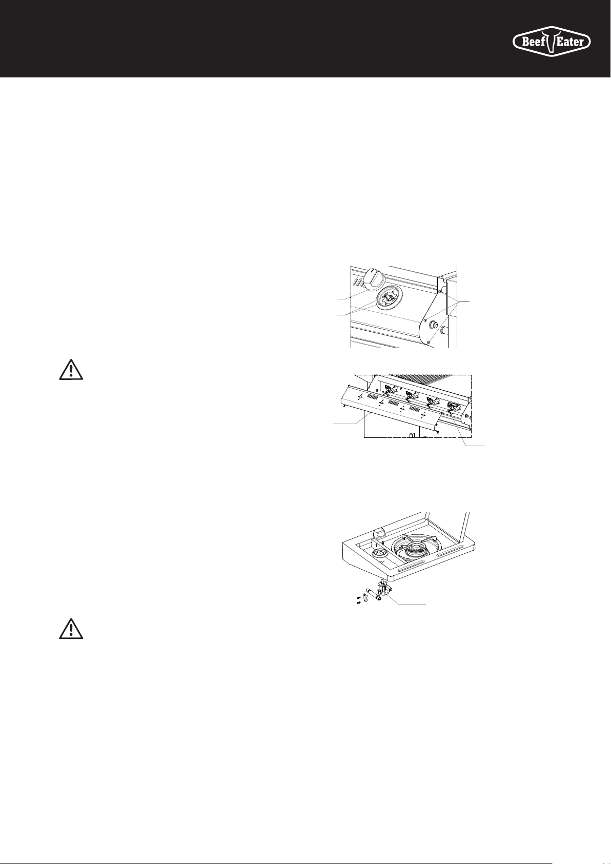
Procedure
1. Remove knobs and for each bezel remove
2 screws retaining the bezel to the valve.
2. At each end of the control panel, remove
3 screws retaining the control panel.
Knob
Screw
3. Remove control panel to access the valves.
4. Remove each valve and replace with valve
provided in the natural gas conversion kit.
5. Remove the hose and regulator assembly, and replace the
hose and regulator appropriate for the intended gas supply.
6. Turn on gas & check for leaks at every connection
(use soap solution to identify leaks.)
7. Replace the control panel, bezels and the knobs.
8. Check and adjust if necessary the supply pressure
is 1.13kPa.
9. The operation of the regulator can be confirmed by
connecting a manometer to the test point located on the
side of the regulator body. With three burners operating
at maximum the outlet pressure should measure 1.0kPa.
Replace the Data Label
Peel the gas type label from backing and cover
existing data label to indicate Natural Gas.
NATURAL GAS CONVERSION INSTRUCTIONS
Knob
Control
panel
Valve
screw
Screw
Screw
Side burner valve
WARNING
WARNING
If you smell gas:
1. Shut off gas to the appliance.
2. Extinguish any open flame.
3. Open lid.
4. If odour continues, immediately call your
gas supplier or your fire department.
WARNING
WARNING
1. Do not store or use gasoline or other flammable vapours
or liquids in the vicinity of this or any other appliance.
2. An LPG cylinder not connected for use shall not be
stored in the vicinity of this or any other appliance.
Technical Data Discovery BBQ
NATURAL GAS CONVERSION INSTRUCTIONS
© 2018 Electrolux Home Products Pty Ltd. ABN 51 004 762 341
BMAN_BD6192_NG_ConvKit_Jan18
NOTE: To convert the BBQ from Natural Gas to LPG, all
of the steps must be reversed including the replacement
of the data label.
For more information on all BeefEater products, or for
dimension and installation information, call into your retailer,
phone or email our customer care team or visit our website:
AUSTRALIA
phone: 1300 307 939
fax: 1800 356 669
email: customercare@electrolux.com.au
web: beefeaterbbq.com
NEW ZEALAND
phone: 0800 436 245
fax: 0800 225 088
email: customercare@electrolux.co.nz
web: beefeaterbbq.com
GAS BARBECUE SIDE BURNER PRESSURE
kPa
Injectors
MM
Total gas consumption (MJ/h) Injectors
MM
Total gas
consumption
(MJ/h)
4 Burner 5 Burner
Universal LPG 1.10 60 75 1.10 16.0 2.75
Natural gas 1.80 60 75 1.80 15.0 1.00
