
i
Trademarks
OTOFIX is a trademark powered by Autel Intelligent Technology Corp., Ltd., registered in
China, the United States and other countries. All other marks are trademarks or registered
trademarks of their respective holders.
Copyright Information
No part of this manual may be reproduced, stored in a retrieval system or transmitted, in
any form or by any means, electronic, mechanical, photocopying, recording, or otherwise
without the prior written permission of Autel Intelligent Technology Corp., Ltd.
Disclaimer of Warranties and Limitation of Liabilities
All information, specifications and illustrations in this manual are based on the latest
information available at the time of printing.
Autel Intelligent Technology Corp., Ltd. reserves the right to make changes at any time
without notice. While information of this manual has been carefully checked for accuracy,
no guarantee is given for the completeness and correctness of the contents, including but
not limited to the product specifications, functions, and illustrations.
Autel Intelligent Technology Corp., Ltd. will not be liable for any direct, special, incidental,
indirect damages or any economic consequential damages (including the loss of profits).
IMPORTANT
Before operating or maintaining this unit, please read this manual carefully, paying extra
attention to the safety warnings and precautions.
For Services and Support
www.otofixtech.com
0086-755-86147779 (China)
(833) 686-1349 (OTO-1FIX) (North America)
For technical assistance in all other markets, please contact your local selling agent.

ii
Safety Information
For your own safety and the safety of others, and to prevent damage to the device and
vehicles upon which it is used, it is important that the safety instructions presented
throughout this manual be read and understood by all persons operating or coming into
contact with the device.
There are various procedures, techniques, tools, and parts for servicing vehicles, as well
as in the skill of the person doing the work. Because of the vast number of test applications
and variations in the products that can be tested with this equipment, we cannot possibly
anticipate or provide advice or safety messages to cover every circumstance. It is the
automotive technician’s responsibility to be knowledgeable of the system being tested. It
is crucial to use proper service methods and test procedures. It is essential to perform
tests in an appropriate and acceptable manner that does not endanger your safety, the
safety of others in the work area, the device being used, or the vehicle being tested.
Before using the device, always refer to and follow the safety messages and applicable
test procedures provided by the manufacturer of the vehicle or equipment being tested.
Use the device only as described in this manual. Read, understand, and follow all safety
messages and instructions in this manual.
Safety Messages
Safety messages are provided to help prevent personal injury and equipment damage. All
safety messages are introduced by a signal word indicating the hazard level.
DANGER
Indicates an imminently hazardous situation which, if not avoided, will result in death or
serious injury to the operator or to bystanders.
WARNING
Indicates a potentially hazardous situation which, if not avoided, could result in death or
serious injury to the operator or to bystanders.
Safety Instructions
The safety messages herein cover situations Autel Intelligent Technology Corp., Ltd. is
aware of. Autel Intelligent Technology Corp., Ltd. cannot know, evaluate or advise you as
to all of the possible hazards. You must be certain that any condition or service procedure
encountered does not jeopardize your personal safety.

iii
DANGER
When an engine is operating, keep the service area WELL VENTILATED or attach a
building exhaust removal system to the engine exhaust system. Engines produce carbon
monoxide, an odorless, poisonous gas that causes slower reaction time and can lead to
serious personal injury or loss of life.
SAFETY WARNINGS
Wear safety glasses and protective clothing.
NEVER smoke or allow a spark or flame in vicinity of battery or engine.
Have plenty of fresh water and soap nearby in case battery acid contacts skin, clothing
or eyes.
If battery acid contacts skin or clothing, wash immediately with soap and water. If acid
enters eye, immediately flush eye with cold running water for at least ten minutes and
get medical attention immediately.
Use caution when working with metallic tools to prevent sparks or short circuits.
Remove any jewelry or watches before you start servicing the battery.
Keep hair, hands, and clothing as well as tester leads and cords away from moving
blades and belts.

iv
CONTENTS
SAFETY INFORMATION ................................................................................................ ii
SAFETY MESSAGES ..................................................................................................... ii
SAFETY INSTRUCTIONS .............................................................................................. ii
1 USING THIS MANUAL ................................................................................................... 1
CONVENTIONS ................................................................................................................... 1
2 GENERAL INTRODUCTION .......................................................................................... 3
2.1 OTOFIX BT1 LITE TESTER .......................................................................................... 4
2.1.1 Function Description........................................................................................ 4
2.1.2 Power Sources ................................................................................................ 5
2.1.3 Technical Specifications .................................................................................. 6
3 GETTING STARTED ...................................................................................................... 7
3.1 POWER UP .................................................................................................................. 7
3.1.1 Application Buttons ......................................................................................... 9
3.2 TEST PREPARATION ...................................................................................................... 9
3.2.1 Inspect the Battery .......................................................................................... 9
3.2.2 Connecting to a Battery ................................................................................. 10
4 IN-VEHICLE TEST ........................................................................................................ 11
4.1 START THE TEST ........................................................................................................ 12
4.1.1 Confirm Vehicle Information .......................................................................... 13
4.2 BATTERY TEST ........................................................................................................... 15
4.3 STARTER TEST ........................................................................................................... 19
4.4 GENERATOR TEST ...................................................................................................... 20
5 OUT-VEHICLE TEST .................................................................................................... 22
5.1 TEST PROCEDURE ...................................................................................................... 22
5.2 TEST RESULTS ........................................................................................................... 24
6 HISTORY ...................................................................................................................... 25
7 REPAIR REPORTS ...................................................................................................... 26
8 UPDATE ....................................................................................................................... 27
8 ME ................................................................................................................................. 28
8.1 DATA LOGGING .......................................................................................................... 29
8.2 BAS MANAGER .......................................................................................................... 29
8.3 SETTINGS .................................................................................................................. 31

v
8.4 USER MANUAL ........................................................................................................... 31
9 MAINTENANCE AND SERVICE .................................................................................. 32
9.1 MAINTENANCE INSTRUCTIONS ...................................................................................... 32
9.2 TROUBLESHOOTING CHECKLIST ................................................................................... 33
9.3 ABOUT BATTERY USAGE ............................................................................................. 34
9.4 SERVICE PROCEDURES ............................................................................................... 35
9.4.1 Technical Support ......................................................................................... 35
9.4.2 Repair Service ............................................................................................... 36
10 COMPLIANCE INFORMATION.................................................................................... 37
11 WARRANTY ................................................................................................................. 39

1
1 Using This Manual
This manual contains device usage instructions.
Some illustrations shown in this manual may contain modules and optional equipment
that are not included in your system. Contact your sales representative for availability of
other modules and optional tools or accessories.
Conventions
The following conventions are used.
Bold Text
Bold text is used to highlight selectable items such as buttons and menu options.
Example:
Tap OK.
Notes and Important Messages
Notes
A NOTE provides helpful information such as additional explanations, tips, and comments.
Example:
NOTE
New batteries reach full capacity after approximately 3 to 5 charging and discharging
cycles.

2
Important
IMPORTANT indicates a situation which, if not avoided, may result in damage to the test
equipment or vehicle.
Example:
IMPORTANT
Keep the cable away from heat, oil, sharp edges and moving parts. Replace damaged
cables immediately.
Hyperlink
Hyperlinks, or links, that take you to other related articles, procedures, and illustrations
are available in electronic documents. Blue italic text indicates an internal link and blue
underlined text indicates a website link or an email address link.
Illustrations
Illustrations used in this manual are samples, the actual testing screen may vary for each
vehicle being tested. Observe the menu titles and on-screen instructions to select the
appropriate options.

3
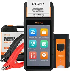
2 General Introduction
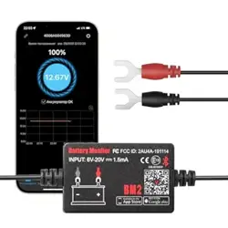
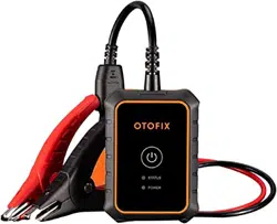
OTOFIX BT1 Lite
Smart Battery Tester
The BT1 Lite is a battery and cranking/charging system analysis tool that uses
Adaptive Conductance, an advanced battery analysis method to produce a
more accurate examination of the battery’s cold cranking ability and reserve
capacity, vital to determining a battery’s true health. The BT1 Lite enables
technicians to view the health status of the vehicle's battery and
cranking/charging system. Download the free and easy-to-use Battery Test
mobile app that is available for iOS and Android devices. Together with the BT1
Lite, this app can complete battery & cranking and charging system tests and
display the test results.
4
2.1 OTOFIX BT1 Lite Tester
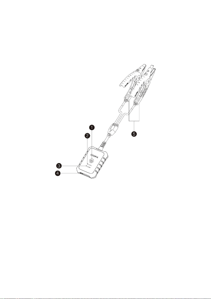
2.1.1 Function Description
Figure 2-1 OTOFIX BT1 Lite
1. Power Button
2. Status LED
3. Power LED
4. USB Port
5. Battery Clamp Cable

5
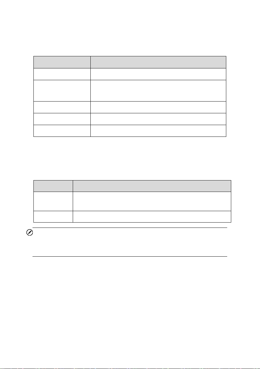
Table 2-1 LED Description
LED
Color
Description
Status
LED
Flashing
Green
The tester is communicating via USB
cable.
Flashing
Blue
The tester is communicating via
Bluetooth.
Flashing
Red
Battery clamps are connected to the
wrong battery terminals.
Power
LED
Green
Solid Green: The tester is
powered on and the battery is
sufficiently charged.
Flashing Green: The tester is
charging. (Becomes solid green
when battery is fully charged.)
Red
Flashing Red: The battery level is
low. Please charge.
Solid Red: The device is in boot
mode.
2.1.2 Power Sources
The BT1 Lite tester can receive power from the following sources:
Internal Battery Pack
AC/DC Power Supply
IMPORTANT
Do not charge the battery when the temperature is below 0°C (32°F) or above
45°C (113°F).

6
1. Internal Battery Pack
The BT1 Lite can be powered with the internal rechargeable battery.
2. AC/DC Power Supply — Using Power Adapter
The tester can be powered from an electrical outlet using the AC/DC power
adapter. The AC/DC power supply also charges the internal battery pack.
2.1.3 Technical Specifications
Item
Description
Connectivity
USB 2.0, Type C
Bluetooth 4.2
Input Voltage
5 V DC
Working Current
< 150 mA at 12 V DC
Internal Battery
3.7 V / 800 mAh Lithium-ion Polymer battery
CCA Range
100 to 2000 A
Voltage Range
6 to 36 V
Working Temperature
–10° C to 50° C (14° F to 122° F)
Storage Temperature
–20° C to 60° C (–4° F to 140° F)
Dimension (L x W x H)
107 mm (4.21’’) x 75 mm (2.95”) x 26 mm (1.02”)
(clamp cable not included)
Weight
320 g (0.7 lb.)

7
3 Getting Started
Ensure that the unit is sufficiently charged before use.
NOTE
1. The images and illustrations depicted in this manual may differ slightly
from the actual ones in your use scenario. The user interfaces for iOS &
Android devices might be slightly different. This manual uses the user
interface for Android devices as an example.
2. The Battery Test app is compatible with 64-bit devices only.
3. The BT1 Lite tester can be used with a compatible OTOFIX tablet. Your
tablet’s software may need to be updated for the app to display.
3.1 Power Up
1. Download and install app on your mobile device
Search for Battery Test in Google Play or the Apple App Store to download and
install the app to your device. Alternatively, you can scan the QR code below
to be directed to the Battery Test app download. On an Android device, you will
be directed to Google Play, while iOS users will be directed to the Apple App
Store.

8
2. Register and log in
1) Open the Battery Test app and tap Register on the Log in screen.
2) Follow the on-screen instructions to complete the registration.
3) Log in with your registered email address and password.
3. Pair the BT1 Lite
Pair the BT1 Lite with the Battery Test app by scanning the QR code on the
back of the tester or via Bluetooth pairing.
4. Install the diagnostic data package
Tap the Update button on the Home screen and install the vehicle diagnostic
application.
NOTE
1. If you already have an existing Autel account, log in with your registered
Autel account email and password.
2. If you try to use functions from the main menu without installing the vehicle
software from the Update screen, a message will display on the Home
screen reminding you to install the vehicle software first.
3. The recommended pairing process is by scanning the QR code on the
back of the BT1 Lite.
9
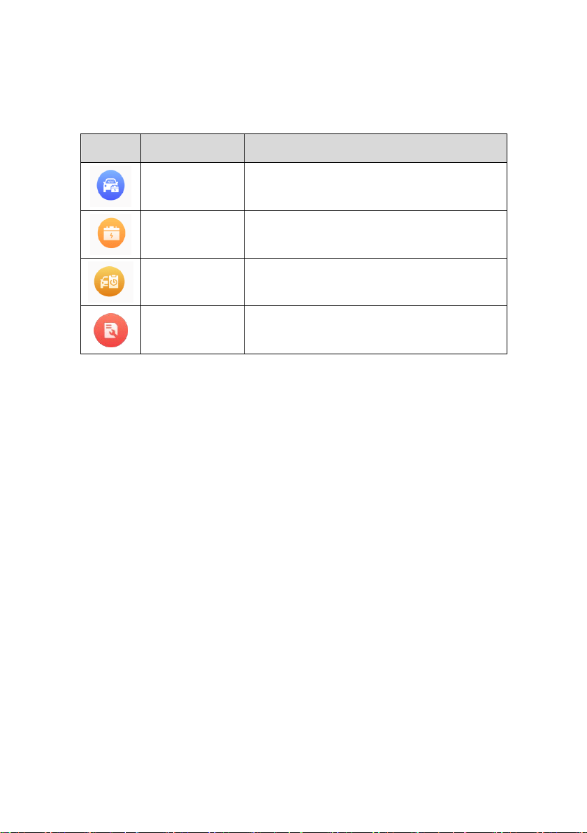
3.1.1 Application Buttons
Button
Name
Description
In-vehicle Test
Tests batteries that are installed in a vehicle.
(See page 11.)
Out-vehicle Test
Tests batteries that are not installed in a
vehicle. (See page 22.)
History
Accesses battery test results.
(See page 25.)
Repair Reports
Accesses stored repair reports.
(See page 26.)
3.2 Test Preparation
3.2.1 Inspect the Battery
Before starting a test, inspect the battery for:
Cracking, buckling or leaking. If you see any of these defects, replace
the battery.
Corroded, loose or damaged cables and connections. Repair or
replace as needed.
Corrosion on the battery terminals, and dirt or acid on the case top.
Clean the case and terminals using a wire brush and a mixture of
water and baking soda.

10
3.2.2 Connecting to a Battery
Press and hold the Lock/Power button to turn on the BT1 Lite.
Connect the red clamp to the positive (+) terminal and the black clamp to
the negative (–) terminal of the battery.
The black clamp is installed with an infrared sensor near the clamp mouth
that tests the battery temperature. The battery temperature will appear on
the Battery Test Result screen or in the Battery Test Reports.

11
4 In-vehicle Test
The in-vehicle test is used for testing batteries that are installed in a vehicle. An
in-vehicle test includes the Battery test, Starter test, and Generator test, and
determines the health status of the battery, the starter, and the generator,
respectively.
IMPORTANT
1. Before using the diagnostic functions, download the desired vehicle software
on the Update screen.
2. A Disclaimer page will appear when accessing any function on the Home
screen for the first time. Please read the end user agreement and TAP Accept
to continue. If you tap Decline, you will not be able to use the features properly.
Figure 4-1 Sample Disclaimer Screen

12
4.1 Start the Test
Select In-vehicle test on the Home screen.
Figure 4-2 Sample Home Screen
1) Home screen — Displays four major functions of the BT1 Lite, including In-
vehicle test, Out-vehicle test, History, and Repair reports.
2) Navigation Button — Displays Home screen, Update and Me. The Update
allows users to install the vehicle diagnostic application. The Me panel
provides information related to the user account, including Data Logging,
BAS Manager, Settings, and User Manual.
13
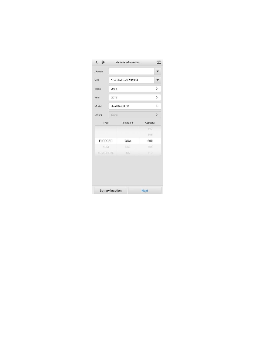
4.1.1 Confirm Vehicle Information
Figure 4-3 Sample Vehicle Information Screen
1. The vehicle information will be automatically populated when vehicle
communication is established. A Battery Information tab will pop up from
the bottom of the screen.
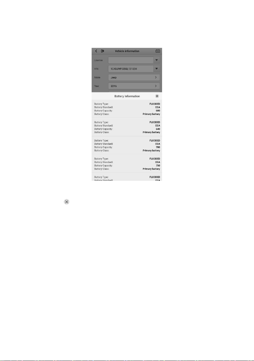
14
Figure 4-4 Sample Battery Information Screen
2. Tap the icon on the tab to return to the Vehicle information screen. Tap
Battery Location on the bottom left corner of the screen and view the
battery location diagram.
3. Find the battery, check the battery information on it and select the correct
battery parameters on the screen.
4. Confirm all the items on the Vehicle information screen. Tap the
corresponding field to manually input the correct parameters, if needed.
Tap Next to continue.
15
4.2 Battery Test
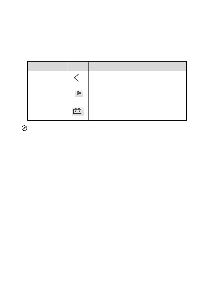
Table 4-1 Upper Toolbar Buttons
NOTE
On an Android device, a tap on the Battery Connection button will display the
BAS Manager screen. On an iOS device, if the tester is not paired, a message
will appear to prompt the user to pair the battery tester. No other action or
screen will be displayed on the iOS device if already paired with the battery
tester.
5. The Clamp Connection Diagram will appear. Follow the instructions to
connect the clamp cables and tap Next to continue.
Name
Button
Description
Back
Returns to the previous screen.
ESC
Returns to the Diagnosis (or Diagnostics)
screen.
Battery
Connection
Displays the battery connection status. The
number on the icon indicates the real-time
voltage of the tested battery.

16
Figure 4-5 Sample Battery Information Screen
6. Follow the on-screen instructions, check the boxes and tap Start Testing.
7. Wait until the test is completed. The test results will appear as shown below:
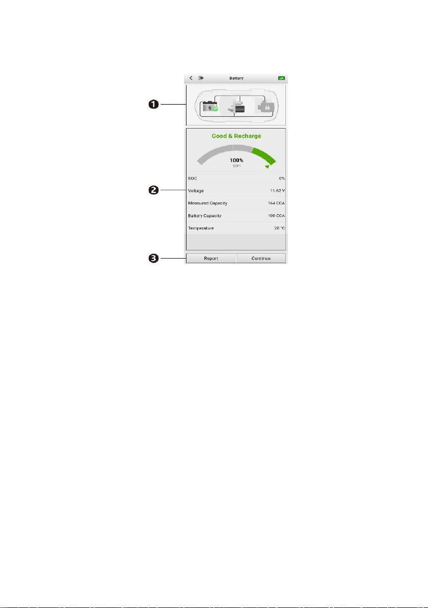
17
Figure 4-6 Sample Battery Test Result Screen
1) Process Buttons
2) Test Report
3) Function Buttons
Process Buttons
Tap any of the process buttons to advance to the corresponding test — battery
test, starter test or generator test. A status icon will appear on the bottom right
corner of the button, indicating the test results.
Battery Test Results
The battery test results include a color-coded results summary, a list of test
data, and repair tips.
18
Table 4-2 Battery Test Results
Result
Repair Tip
Good Battery
Battery is in good condition.
Good & Recharge
Battery is good at present. The battery should be
charged.
Charge & Retest
Charge the battery and retest it.
Bad Cell
Replace the battery.
Replace Battery
Replace the battery.
Function Buttons
The Function Buttons displayed at the bottom of the screen will vary depending
on the operation. The table below provides a brief description of these
operations:
NOTE
Please always complete the Battery test before you proceed to the Starter and
Generator tests.
Name
Description
Report
Tap to view the test data and results in report form. Tap Save
to save test reports as a PDF document.
Continue
Tap to perform the next test.
19
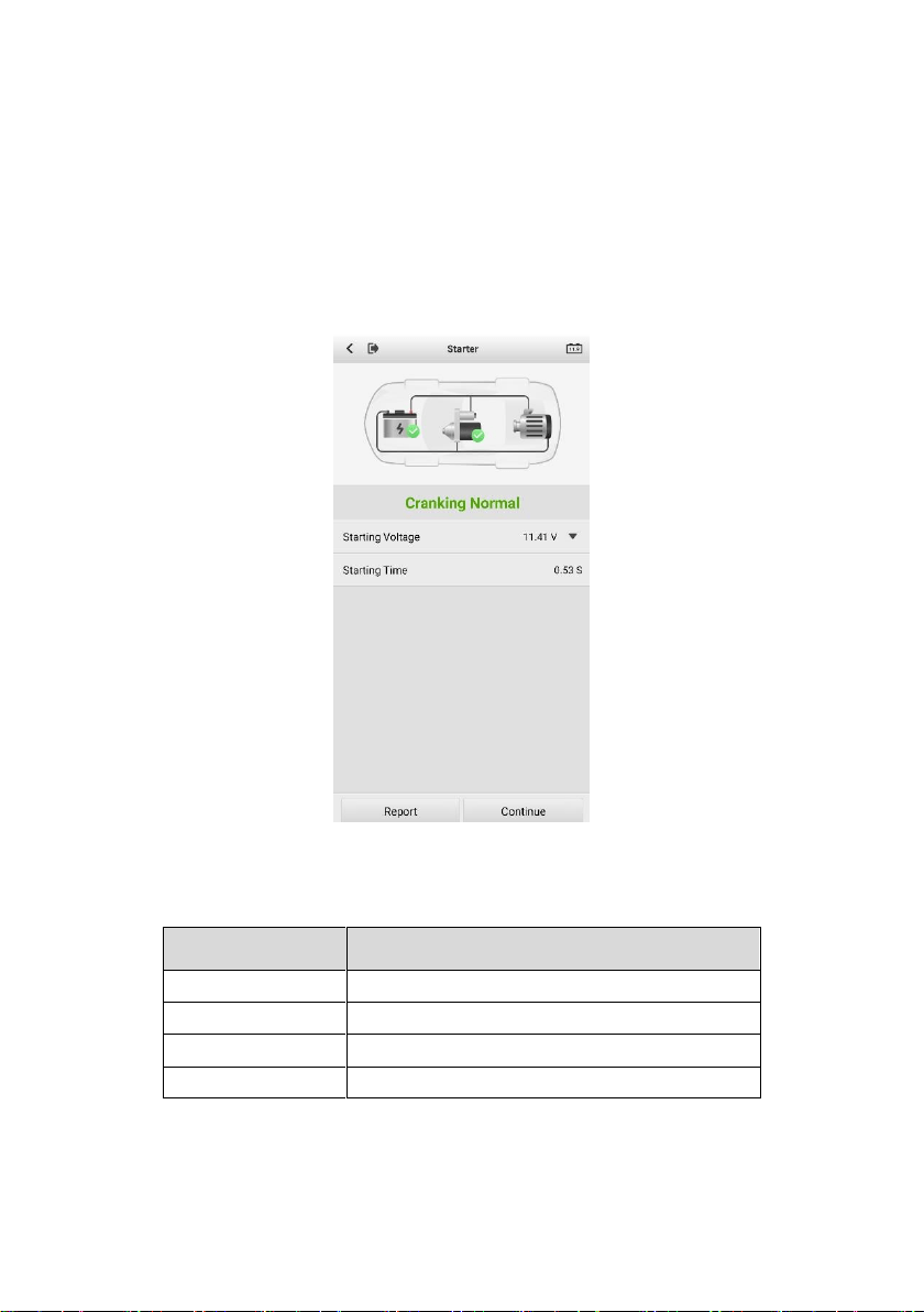
4.3 Starter Test
8. Follow the on-screen instructions to complete the test. Start the engine and
let it idle. The test results will be displayed as follows:
Figure 4-7 Sample Starter Test Results Screen
Table 4-3 Starter Test Results
Result
Description
Cranking Normal
Starter is good.
Current Too Low
Low momentary discharge capacity.
Voltage Too Low
Low battery storage capacity.
Not Started
Starter is not detected for starting.
20
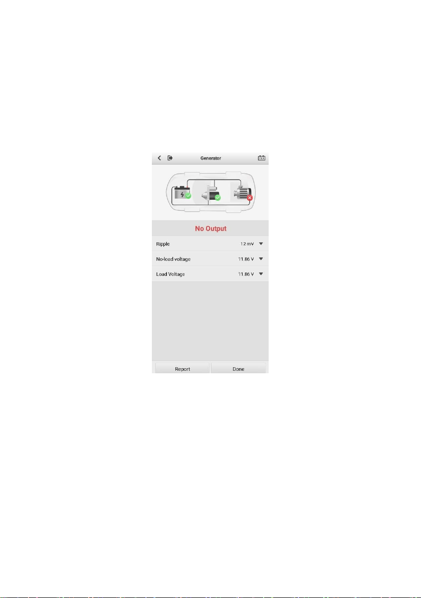
4.4 Generator Test
9. Follow the on-screen instructions to complete the test. The test results will
be displayed as follows:
Figure 4-8 Sample Generator Test Results Screen

21
Table 4-4 Generator Test Results
Result
Description
Charging Normal
The generator is good.
Output Too Low
The belt linking the starter and the
generator is loose;
The cable linking the starter and
battery is loose or corroded.
Output Too High
The generator is not properly
connected to the ground;
The voltage adjuster is broken and
needs replacement.
Ripple Too Large
The commutation diode is broken and
needs repair or replacing.
No Output
The cable is loose.
Some vehicles with power
management systems do not
provide a path for charging due to
the sufficient load capacity of the
battery;
The generator or the voltage
adjuster is broken and needs
replacing.

22
5 Out-vehicle Test
Out-vehicle test is used to test the condition of batteries that are not connected
to a vehicle. This function aims to check the health status of the battery only.
The battery types and standards able to be tested are as follows:
Types: FLOODED, AGM, AGM SPIRAL, EFB, and GEL
Standards: CCA, SAE, CA, EN, IEC, DIN, JIS and MCA
5.1 Test Procedure
1. Connect the clamps to the battery terminals.
2. Select the appropriate battery type, rating standard, and capacity. Tap
Start Testing to start the test.
Figure 5-1 Sample Out-vehicle Test Screen
23
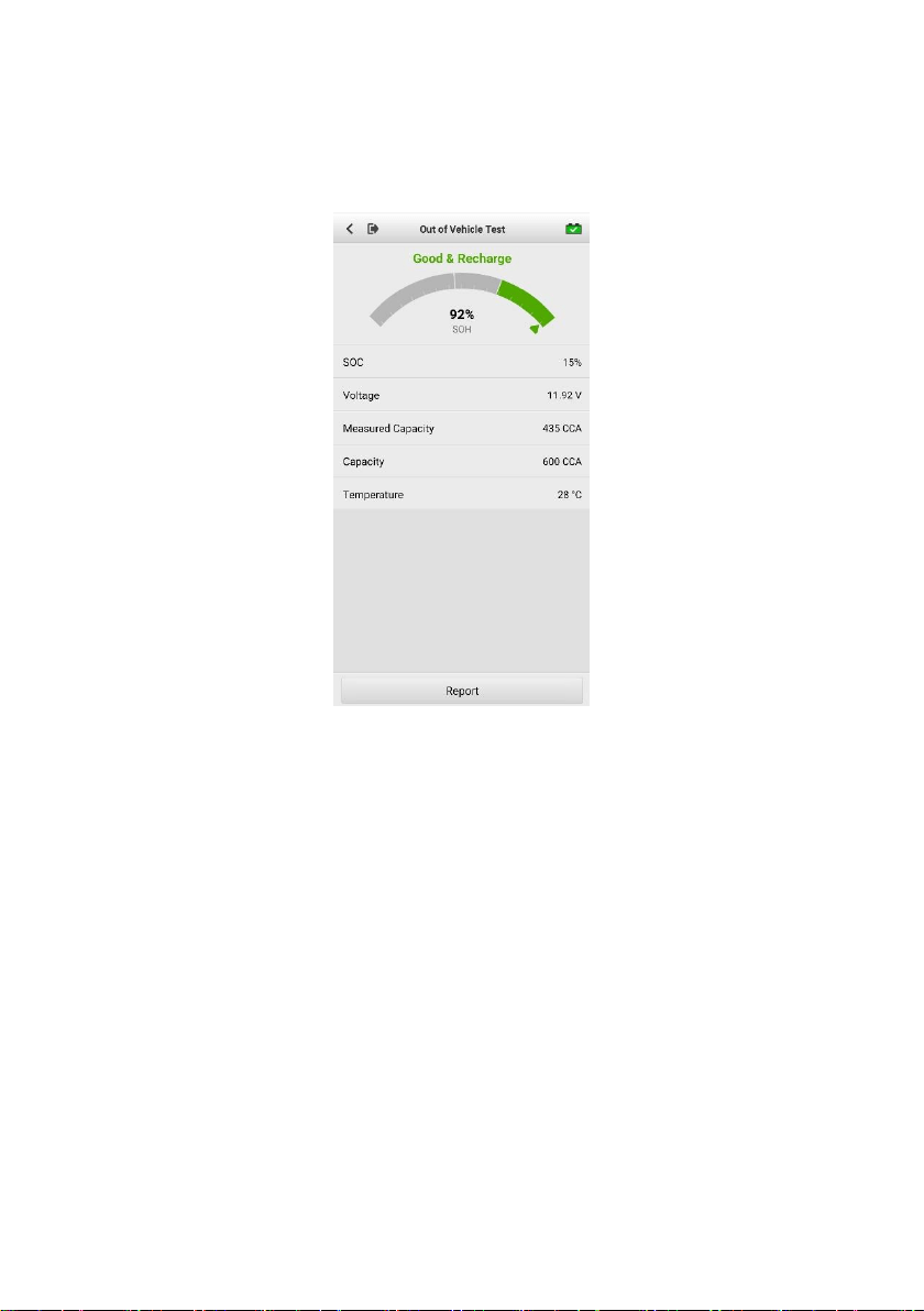
3. The test result will be displayed in a few seconds.
Figure 5-2 Sample Out-vehicle Test Screen

24
5.2 Test Results
Icons are color-coded to indicate status.
Result
Description
Good Battery
Battery meets required standards.
Good & Recharge
Battery is good, but low on charge. Fully charge
the battery. Check for causes of low charge.
Charge & Retest
Retest after charging.
Replace Battery
Battery fails to meet industry-accepted standards.
Bad Cell
Battery fails to meet industry-accepted standards.
25
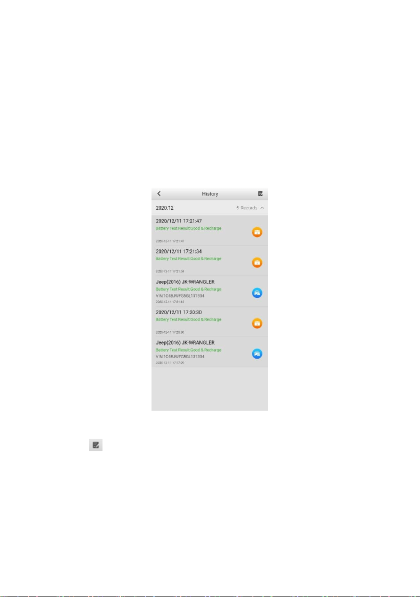
6 History
This function stores results of vehicle and battery testing. The information is
displayed in list form, offering a summary review of just-tested and previously-
tested vehicles and/or batteries.
Figure 6-1 Sample History Screen
Tap the button on the top right corner of the screen to delete the selected
report.

26
7 Repair Reports
The Battery Test app can save a history of repair reports from your diagnostic
sessions. A PDF can also be generated for the easy viewing, sharing, and
printing of these reports.
Figure 7-1 Sample Repair Reports Screen

27
8 Update
The Update function enables users to download and install the vehicle
diagnostic application and software updates as they become available. Please
log in with your Autel ID and pair the OTOFIX BT1 Lite device with your account.
The vehicle software (Battery test) is free and permanently valid. You can
download it through Update.
Figure 8-1 Sample Update Screen
28
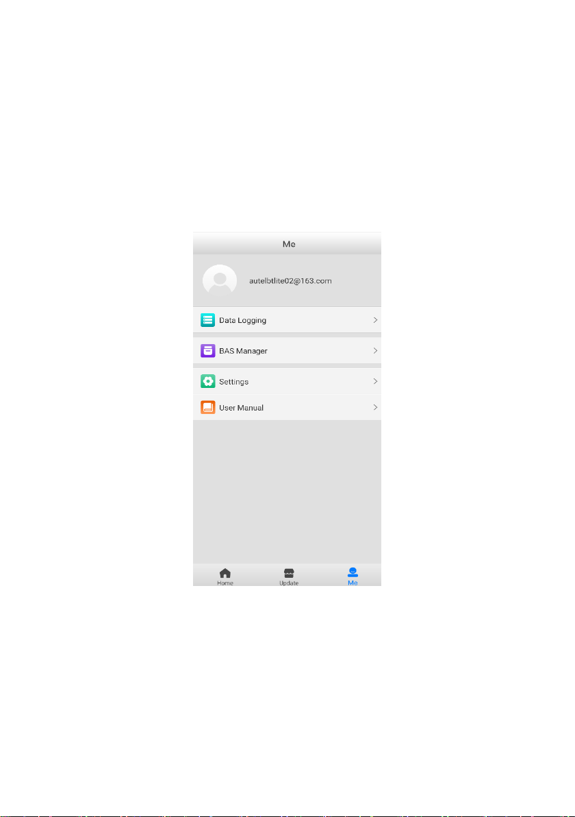
8 Me
In this section, users have access to functions including Data Logging, BAS
Manager, Settings, and User Manual.
Figure 8-1 Sample Me Screen
Registration is required for these functions to be available.

29
To complete registration:
1. Tap the Register button on the Log in screen.
2. Enter your email address. Tap the Verification code button and an
email will be sent to your address with your unique verification code.
Enter the verification code and your account password on the
registration screen.
3. Tap Register to complete the registration.
8.1 Data Logging
The Data Logging option allows you to launch the OTOFIX Support platform
directly to view all records on the diagnostic system. The Data Logging option
keeps all test records, whether submitted (Feedback) or not submitted (Not
Feedback), in addition to a history of your most recent 20 test records (History).
OTOFIX support personnel will receive and process any submitted reports
through the Support platform.
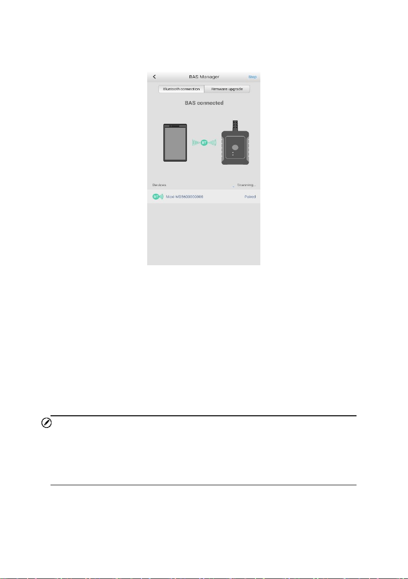
8.2 BAS Manager
The BAS Manager displays Bluetooth connection status, and enables users to
check current firmware version and upgrade it when available.
30
Figure 8-2 Sample BAS Manager Screen
1. Bluetooth connection
Users can pair the mobile device with the BT1 Lite tester via Bluetooth. The
serial number of the tester will display on the screen. Tap Stop on the top right
corner of the screen to stop scanning. If the Bluetooth connection is successful,
the status will display as Paired.
2. Firmware upgrade
Tap Firmware upgrade to check for available updates. Tap the upgrade
notification message to download and install.
NOTE
When initiating a diagnostic function, the screen will display a notification
message to prompt the user to update the firmware if a newer version is
available.

31
8.3 Settings
Select the Settings application to display the settings menu.
Unit
English or Metric measurements can be used. By default, Metric is chosen.
Tap English to have the tool display measures in English units.
Tips Reset
Reset the tips feature to turn on the on-screen guidance when using the tool.
8.4 User Manual
This option launches the User Manual for the OTOFIX BT1 Lite.

32
9 Maintenance and Service
To ensure that your OTOFIX tester performs at its optimum level, we advise
that the product maintenance instructions discussed in this section are read and
followed.
9.1 Maintenance Instructions
Maintain the device with the following precautions and guidance in mind.
Do not use any abrasive cleansers, detergents, or automotive chemicals
on the tester.
Maintain all devices in dry conditions and keep them within normal
operating temperatures.
Do not store the devices in humid, dusty or dirty areas.
Check the housing, wiring, and connectors for dirt and damage before
and after each use.
At the end of each work day, wipe the device housing, wiring, and
connectors clean with a damp cloth.
Do not attempt to disassemble the tester.
Do not drop or cause severe impact to the device.
Use only authorized battery chargers and accessories. Any malfunction
or damage caused by the use of unauthorized battery chargers and
accessories will void the product warranty.
Ensure that the battery charger does not come in contact with conductive
objects.

33
9.2 Troubleshooting Checklist
A. When the tester does not work properly:
Ensure the tester has been registered.
Ensure tool’s firmware is upgraded.
Check all cables, connections, and indicators to ensure proper
communication between tool and vehicle and battery.
B. When you are unable to charge the tester:
Check the connections.
Ensure you are using the power supply included with the tool.
Ensure the tool is being charged in a room of moderate temperature, not
too hot or too cold.
Contact technical support or your authorized OTOFIX supplier if the unit
or charger is damaged.
C. When Bluetooth connection fails:
The Bluetooth signal is out of range. Move the battery tester closer to
your mobile device.
On your mobile device, turn Bluetooth off and then on.
Power your mobile device off and then on.
NOTE
Contact OTOFIX technical support or your authorized OTOFIX supplier if the
problem persists.

34
9.3 About Battery Usage
Your tester is powered by a built-in Lithium-ion Polymer battery. This means
that, unlike other battery technologies, the battery can be recharged with some
remaining battery life without damaging its longevity.
DANGER
1. The built-in Lithium-ion Polymer battery is factory replaceable only;
incorrect replacement or tampering with the battery pack may cause
an explosion.
2. Do not use a damaged battery charger.
Do not disassemble or open, crush, bend or deform, puncture or shred.
Do not modify or remanufacture, attempt to insert foreign objects into
the battery, expose to fire, explosion or other hazards.
Make sure to only use the charger and USB cables that are supplied
with the tool. The use of other chargers and/or USB cables might result
in malfunction or damage to the tool.
Only use the charging device that has been qualified with device per
the standard. Use of an unqualified battery or charger may present a
risk of fire, explosion, leakage, or other hazards.
Avoid dropping the tester. If the tester is dropped, especially on a hard
surface, and the user suspects damage, contact OTOFIX technical
support.
The battery recharging time varies depending on the remaining battery
capacity.
Battery life inevitably shortens over time.
Overcharging may shorten battery life. Remove the tester from its
charger once it is fully charged. Unplug the charger once charging is

35
complete.
Ensure the tool is stored in a dry and moderate temperature area.
Extreme heat or cold may result in damage to the tool and/or its battery.
9.4 Service Procedures
This section introduces information for technical support, repair service, and
application for replacement or optional parts.
9.4.1 Technical Support
If you have any question or problem on the operation of the product, please
contact us.
OTOFIX NORTH AMERICA
Email: [email protected]
Phone: (833) 686-1349 (OTO-1FIX) (Monday-Friday 9am-6pm EST)
Address: 175 Central Avenue, Suite 200, Farmingdale, New York,
USA 11735
OTOFIX CHINA HQ
Phone: 0086-755-2267-2493 (Monday-Friday, 9:00AM-6:00PM
Beijing Time)
Website: www.otofixtech.com
Address: 7th, 8th and 10th floor, Building B1, Zhiyuan, Xueyuan Road,
Xili, Nanshan, Shenzhen, 518055, China.

36
For technical assistance in other markets, please contact your local
distributor.
9.4.2 Repair Service
If it becomes necessary to return your device for repair, please download
the repair service form from www.otofixtech.com, and fill in the form. The
following information must be included:
Contact name
Return address
Telephone number
Product name
Complete description of the problem
Proof-of-purchase for warranty repairs
Preferred method of payment for non-warranty repairs
NOTE
For non-warranty repairs, payment can be made with Visa, Master Card, or
with approved credit terms.
Send the device to your local distributor, or to the below address:
7th, 8th and 10th Floor, Building B1, Zhiyuan, Xueyuan Road, Xili, Nanshan,
Shenzhen, 518055, China

37
10 Compliance Information
FCC Compliance FCC ID: WQ8BATS-BT508
This device complies with part 15 of the FCC Rules. Operation is subject to
the following two conditions:
a) This device may not cause harmful interference, and
b) This device must accept any interference received, including
interference that may cause undesired operation.
WARNING
Changes or modifications not expressly approved by the party responsible for
compliance could void the user’s authority to operate the equipment.
NOTE
This equipment has been tested and found to comply with the limits for a Class
B digital device, pursuant to Part 15 of the FCC Rules. These limits are designed
to provide reasonable protection against harmful interference in a residential
installation.
This equipment generates uses and can radiate radio frequency energy and, if
not installed and used in accordance with the instructions, may cause harmful
interference to radio communications. However, there is no guarantee that
interference will not occur in a particular installation. If this equipment does
cause harmful interference to radio or television reception, which can be
determined by turning the equipment off and on, the user is encouraged to try
to correct the interference by one or more of the following measures:
-- Reorient or relocate the receiving antenna.

38
-- Increase the separation between the equipment and receiver.
-- Connect the equipment into an outlet on a circuit different from that to which
the receiver is connected.
-- Consult the dealer or an experienced radio/TV technician for help.
FCC Radiation Exposure Statement
This equipment complies with FCC radiation exposure limits set forth for an
uncontrolled environment. This equipment should be installed and operated
with minimum distance 20cm between the radiator & your body.
RF Warning Statement
The device has been evaluated to meet general RF exposure requirement.
The device can be used in portable exposure condition without restriction.
RF ETSIEN300328 V2.2.2(2019-07)
RoHS COMPLIANCE
This device is declared to be in compliance with the European RoHS Directive
2011/65/EU and Directive(EU)2015/863. IEC62321
CE COMPLIANCE
This product is declared to conform to the essential requirements of the
following Directives and carries the CE mark accordingly:
EMC ETSIEN301489-1 V2.2.3(2019-11) ETSIEN301489-17 V3.1.1(2017-
02)
Safety EN62368-1:2014+A11:2017
Health EN50663:2017:EN62479:2010
Directive 2014/53/EU

39
11 Warranty
Limited One Year Warranty
Autel Intelligent Technology Corp., Ltd. (the Company) warrants to the original
retail purchaser of this OTOFIX battery tester, that should this product or any
part thereof during normal consumer usage and conditions, be proven defective
in material or workmanship that results in product failure within one (1) year
period from the date of purchase, such defect(s) will be repaired, or replaced
(with new or rebuilt parts) with Proof of Purchase, at the Company’s option,
without charge for parts or labor directly related to the defect(s).
The Company shall not be liable for any incidental or consequential damages
arising from the use, misuse, or mounting of the device. Some states do not
allow limitation on how long an implied warranty lasts, so the above limitations
may not apply to you.
This warranty does not apply to:
a) Products subjected to abnormal use or conditions, accident,
mishandling, neglect, unauthorized alteration, misuse, improper
installation or repair or improper storage;
b) Products whose mechanical serial number or electronic serial number
has been removed, altered or defaced;
c) Damage from exposure to excessive temperatures or extreme
environmental conditions;
d) Damage resulting from connection to, or use of any accessory or other
product not approved or authorized by the Company;
e) Defects in appearance, cosmetic, decorative or structural items such
as framing and non-operative parts.
f) Products damaged from external causes such as fire, dirt, sand, battery
leakage, blown fuse, theft or improper usage of any electrical source.

40
IMPORTANT
All contents of the product may be deleted during the process of repair. You
should create a back-up copy of any contents of your product before
delivering the product for warranty service.