
i
Trademarks
OTOFIX is a trademark of Autel Intelligent Technology Corp., Ltd.,
registered in China, the United States, and other countries. All other marks
are trademarks or registered trademarks of their respective holders.
Copyright Information
No part of this manual may be reproduced, stored in a retrieval system or
transmitted, in any form or by any means, electronic, mechanical,
photocopying, recording, or otherwise without the prior written permission
of Autel Intelligent Technology Corp., Ltd.
Disclaimer of Warranties and Limitation of Liabilities
All information, specifications and illustrations in this manual are based on
the latest information available at the time of printing.
Autel Intelligent Technology Corp., Ltd. reserves the right to make changes
at any time without notice. While information of this manual has been
carefully checked for accuracy, no guarantee is given for the completeness
and correctness of the contents, including but not limited to the product
specifications, functions, and illustrations.
Autel Intelligent Technology Corp., Ltd. will not be liable for any direct,
special, incidental, indirect damages or any economic consequential
damages (including the loss of profits).
IMPORTANT
Before operating or maintaining this unit, please read this manual carefully,
paying extra attention to the safety warnings and precautions.
For Services and Support
www.otofixtech.com
(833) 686-1349 (OTO-1FIX) (North America)
0086-755-86147779 (China)
For technical assistance in all other markets, please contact your local
selling agent.

ii
Safety Information
For your own safety and the safety of others, and to prevent damage to the
device and vehicles upon which it is used, it is important that the safety
instructions presented throughout this manual be read and understood by
all persons operating or coming into contact with the device.
There are various procedures, techniques, tools, and parts for servicing
vehicles, as well as in the skill of the person doing the work. Because of the
vast number of test applications and variations in the products that can be
tested with this equipment, we cannot possibly anticipate or provide advice
or safety messages to cover every circumstance. It is the automotive
technician’s responsibility to be knowledgeable of the system being tested.
It is crucial to use proper service methods and test procedures. It is
essential to perform tests in an appropriate and acceptable manner that
does not endanger your safety, the safety of others in the work area, the
device being used, or the vehicle being tested.
Before using the device, always refer to and follow the safety messages
and applicable test procedures provided by the manufacturer of the vehicle
or equipment being tested. Use the device only as described in this manual.
Read, understand, and follow all safety messages and instructions in this
manual.
Safety Messages
Safety messages are provided to help prevent personal injury and
equipment damage. All safety messages are introduced by a signal word
indicating the hazard level.
DANGER
Indicates an imminently hazardous situation which, if not avoided, will result
in death or serious injury to the operator or to bystanders.
WARNING
Indicates a potentially hazardous situation which, if not avoided, could result
in death or serious injury to the operator or to bystanders.
Safety Instructions

iii
The safety messages herein cover situations Autel Intelligent Technology
Corp., Ltd. is aware of. Autel Intelligent Technology Corp., Ltd. cannot know,
evaluate or advise you as to all of the possible hazards. You must be certain
that any condition or service procedure encountered does not jeopardize
your personal safety.
DANGER
When an engine is operating, keep the service area WELL VENTILATED or
attach a building exhaust removal system to the engine exhaust system.
Engines produce carbon monoxide, an odorless, poisonous gas that causes
slower reaction time and can lead to serious personal injury or loss of life.
SAFETY WARNINGS
Wear safety glasses and protective clothing.
NEVER smoke or allow a spark or flame in the vicinity of battery or
engine.
Have plenty of fresh water and soap nearby in case battery acid
contacts skin, clothing or eyes.
If battery acid contacts skin or clothing, wash immediately with soap
and water. If acid enters eye, immediately flush eye with running cold
water for at least ten minutes and get medical attention immediately.
Use caution when working with metallic tools to prevent sparks or short
circuits.
Remove any jewelry or watches before you start servicing the battery.
Keep hair, hands, and clothing as well as tester leads and cords away
from moving blades and belts.

iv
CONTENTS
SAFETY INFORMATION ........................................................................... ii
SAFETY MESSAGES ................................................................................ ii
SAFETY INSTRUCTIONS ......................................................................... ii
USING THIS MANUAL ............................................................................. 1
1.1 CONVENTIONS ....................................................................................... 1
GENERAL INTRODUCTION .................................................................... 3
2.1 OTOFIX BT1 BATTERY TESTER ............................................................. 4
2.1.1 Function Description ..................................................................... 4
2.1.2 Power Sources .............................................................................. 5
2.1.3 Technical Specifications ............................................................... 6
2.2 OTOFIX V1 — VEHICLE COMMUNICATION INTERFACE (VCI) ..................... 6
2.2.1 Function Description ..................................................................... 7
2.2.2 Power Sources .............................................................................. 8
2.2.3 Technical Specifications ............................................................... 8
2.3 OTHER ACCESSORIES ............................................................................. 9
GETTING STARTED .............................................................................. 10
3.1 POWER UP .......................................................................................... 10
3.1.1 Page Indicator and System Status Bar ....................................... 11
3.1.2 Application Buttons ..................................................................... 11
3.1.3 Drop-down Menu ........................................................................ 13
3.2 POWER OFF ......................................................................................... 14
3.3 TEST PREPARATION .............................................................................. 14
3.3.1 Inspecting the Battery ................................................................. 14
3.3.2 Connecting to a Battery .............................................................. 14
IN-VEHICLE TEST .................................................................................. 16
4.1 START THE TEST .................................................................................. 16
4.1.1 VCI Connection ........................................................................... 17
4.2 BATTERY TEST ..................................................................................... 20
4.3 STARTER TEST ..................................................................................... 22
4.4 GENERATOR TEST ................................................................................ 23
OUT-VEHICLE TEST .............................................................................. 25

v
5.1 TEST PROCEDURE ................................................................................ 25
5.2 TEST RESULTS ..................................................................................... 26
BATTERY REPLACE ............................................................................. 27
BATTERY RESET .................................................................................. 29
7.1 AUTO REGISTRATION (AFTER BATTERY REPLACEMENT) ............................ 29
7.1.1 BMS Reset .................................................................................. 29
7.1.2 Electric Appliance Reset ............................................................. 30
7.2 SPECIAL FUNCTION ............................................................................... 31
7.3 BATTERY USAGE HISTORY (ONLY FOR BMW VEHICLES) ........................... 32
DIAGNOSTICS (SUBSCRIPTION ONLY) .............................................. 33
8.1 AUTO SCAN ......................................................................................... 34
8.2 CONTROL UNITS ................................................................................... 35
8.2.1 ECU Information ......................................................................... 36
8.2.2 Read Codes ................................................................................ 37
8.2.3 Erase Codes ............................................................................... 38
MULTIMETER ......................................................................................... 40
9.1 SAFETY INFORMATION ........................................................................... 40
9.2 GETTING STARTED ............................................................................... 41
9.3 SCREEN LAYOUT AND OPERATION .......................................................... 42
9.3.1 Multimeter Icon ........................................................................... 43
9.3.2 Digital Display ............................................................................. 43
9.3.3 Main View Section ...................................................................... 43
9.3.4 Measurement Type Selection ..................................................... 44
UPDATE ................................................................................................ 46
SETTINGS ............................................................................................. 48
DATA MANAGER ................................................................................. 49
12.1 TEST RECORDS .................................................................................. 49
12.2 WORKSHOP INFORMATION ................................................................... 50
12.3 IMAGE ................................................................................................ 50
12.4 PDF .................................................................................................. 50
12.5 UNINSTALL APPS ................................................................................ 50
12.6 DATA LOGGING ................................................................................... 50

vi
REMOTE DESKTOP ............................................................................. 52
REGISTER TOOL ................................................................................. 54
14.1 REGISTRATION VIA TESTER .................................................................. 54
14.2 REGISTRATION VIA AN INTERNET BROWSER ON A COMPUTER OR MOBILE
DEVICE ..................................................................................................... 54
MAINTENANCE AND SERVICE ........................................................... 55
15.1 MAINTENANCE INSTRUCTIONS .............................................................. 55
15.2 TROUBLESHOOTING CHECKLIST ............................................................ 56
15.3 ABOUT BATTERY USAGE ...................................................................... 56
15.4 SERVICE PROCEDURES ....................................................................... 57
15.4.1 Technical Support ..................................................................... 57
15.4.2 Repair Service .......................................................................... 58
16 COMPLIANCE INFORMATION ............................................................ 59
17 WARRANTY .......................................................................................... 61
17.1 LIMITED ONE YEAR WARRANTY ......................................................... 61

1
Using This Manual
This manual contains device usage instructions.
Some illustrations shown in this manual may contain modules and optional
equipment that are not included in your system. Contact your sales
representative for availability of other modules and optional tools or
accessories.
1.1 Conventions
The following conventions are used.
Bold Text
Bold text is used to highlight selectable items such as buttons and menu
options.
Example:
Tap OK.
Notes and Important Messages
Notes
A NOTE provides helpful information such as additional explanations, tips,
and comments.
Example:
NOTE
New Batteries reach full capacity after approximately 3 to 5 charging and
discharging cycles.

2
Important
IMPORTANT indicates a situation which, if not avoided, may result in
damage to the test equipment or vehicle.
Example:
IMPORTANT
Keep the cable away from heat, oil, sharp edges and moving parts. Replace
damaged cables immediately.
Hyperlink
Hyperlinks, or links, that take you to other related articles, procedures, and
illustrations are available in electronic documents. Blue italic text indicates a
selectable hyperlink and blue underlined text indicates a website link or an
email address link.
Illustrations
Illustrations used in this manual are samples, the actual testing screen may
vary for each vehicle being tested. Observe the menu titles and the on-
screen instructions to make correct option selection.
Procedures
An arrow icon indicates a procedure.
Example:
To use the camera:
1. Tap the Camera button. The camera screen opens.
2. Focus the image to be captured in the view finder.
3. Tap the camera icon on the right side of the screen. The view finder
now shows the captured picture and auto-saves the taken photo.
4. Tap the thumbnail image on the top right corner of the screen to
view the stored image.
5. Tap the Back or Home button to exit the camera application.

3
General Introduction
OTOFIX BT1
Smart Touchscreen Battery Analyzer
The OTOFIX BT1 smart touchscreen battery analyzer is a full-featured battery
and starting/charging systems diagnostics tool. The OTOFIX BT1 uses a
technology called Adaptive Conductance to more accurately determine the
health of battery than traditional battery testers. The OTOFIX BT1 can quickly
display both voltage and health status of the existing battery, register a new
battery, and perform advanced battery and electrical diagnostics. The OTOFIX
BT1 is also an advanced diagnostics tool that can identify faults in all systems
and display live data relating to those faults. (The all systems diagnostics
function is available by subscription.) The easy-to-use Android-based
touchscreen tool provides Wi-Fi software updates as well as Wi-Fi printing and
sharing of the shop-customized reports which can be printed out with the built-
in thermal printer.
There are two main components to the OTOFIX BT1:
OTOFIX BT1 Tester — the smart touchscreen battery analyzer
OTOFIX V1 — Vehicle Communication Interface (VCI)
4
2.1 OTOFIX BT1 Battery Tester
2.1.1 Function Description
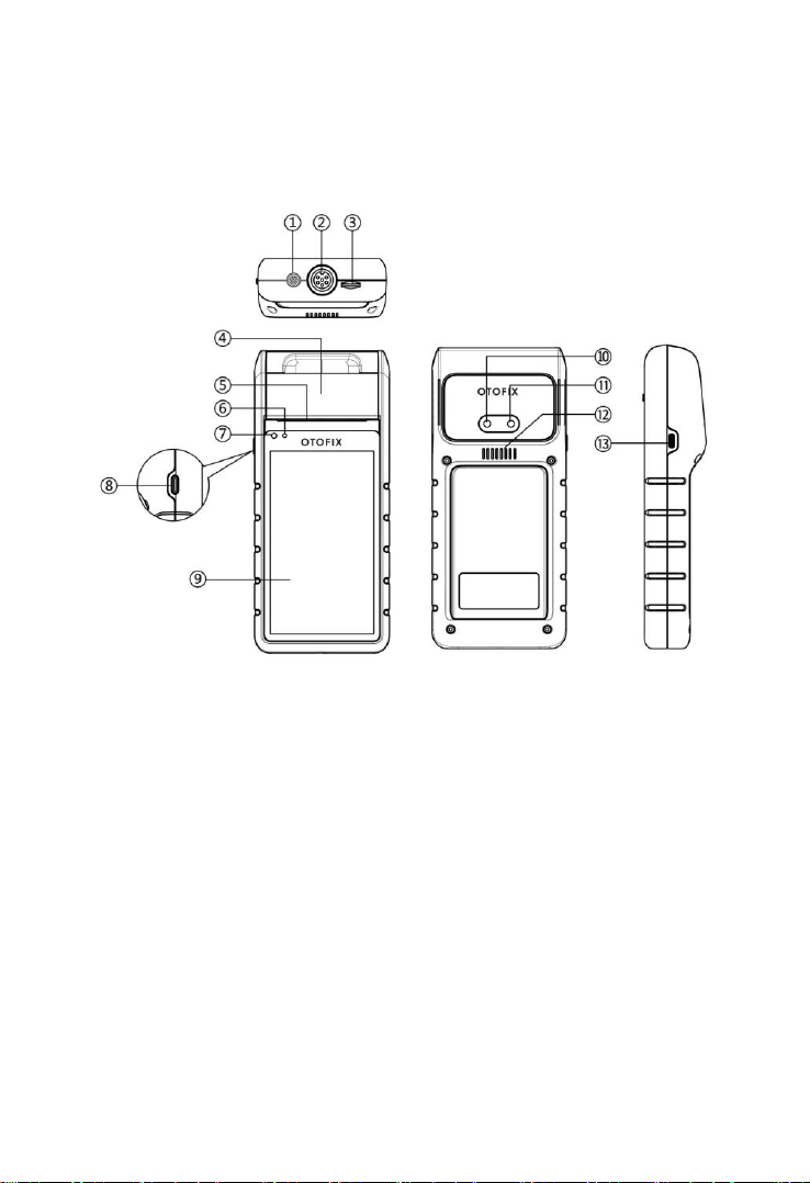
Figure 2-1 OTOFIX BT1 Front/Back/Side View
1. Multimeter Cable Port
2. Battery Clamp Cable Port
3. Micro SD Card Slot
4. Thermal Printer
5. Paper Exit
6. Power LED — refer to Table 2-1 Power LED Description for details
7. Ambient Light Sensor — detects ambient brightness
8. Lock/Power Button — press and hold to turn on and off/restart the tool,
or tap to lock the screen
9. 5.5-inch Touchscreen

5
10. Camera
11. Camera Flash
12. Speaker
13. USB Port
Table 2-1 Power LED Description
LED
Color
Description
Power
Green
Lights solid green when the battery is fully
charged.
Flashes green while charging, and the
tester will automatically powers on.
Red
Lights red when the tester is powered on
and the battery level is below 15%.
Lights red when illegal operation is
detected.
2.1.2 Power Sources
The OTOFIX BT1 tester can receive power from the following sources:
Internal Battery Pack
AC/DC Power Supply
IMPORTANT
Do not charge the battery when the temperature is below 0°C (32°F) or above
45°C (113°F).
Internal Battery Pack
The OTOFIX BT1 is powered via its internal rechargeable battery, which can
provide sufficient power for about 6 hours of continuous operation if fully
charged.
AC/DC Power Supply — using power adapter
The tester can be powered via an electrical outlet using the AC/DC power
adapter. The AC/DC power supply also charges the internal battery pack.

6
2.1.3 Technical Specifications
2.2 OTOFIX V1 — Vehicle Communication
Interface (VCI)
The OTOFIX V1 is a small vehicle communication interface (VCI) that attaches
to a vehicle’s diagnostic connector (DLC) and connects wirelessly to OTOFIX
tools (including battery test tools and OTOFIX tablets) for vehicle data
transmission.
Item
Description
Operating System
Android 9.0
Screen Display
5.5'' LCD touchscreen with 720x1280 resolution
Storage
32 GB
Connectivity
Wi-Fi (802.11 a/b/g/n/ac)
USB 2.0, Type C
BT 5.0 + EDR
Camera
8 Megapixel
Input Voltage
5 V DC
Working Current
< 450 mA at 7.7 V DC
Internal Battery
7.7 V, 3000 mAh
CCA Range
100 to 3000 A
Voltage Range
1.5 V to 36 V
Working Temperature
0°C to 50°C (32°F to 122°F)
Storage Temperature
-10°C to 60°C (14°F to 140°F)
Dimension (L x W x H)
204mm (8.03”) x 90mm (3.54”) x 32mm (1.25”)
Weight
510 g (1.12 lb.)
7
NOTE
The OTOFIX V1 may or may not be included in your package(s) depending on
your order. If this VCI device is not included in your package(s) and you need
one, please contact your local distributor or OTOFIX customer service.
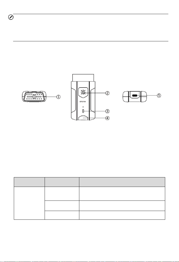
2.2.1 Function Description
1. Vehicle Data Connector (16-pin)
2. Flashlight Power Button
3. Power LED
4. Vehicle/Connection LED
5. USB Port
VCI LED Description
LED
Color
Description
Power LED
Yellow
VCI is powered on and performing self-
check.
Green
VCI is ready for use.
Flashing Red
Firmware is upgrading.

8
LED
Color
Description
Vehicle /
Connection
LED
Green
Solid Green: VCI is connected via
USB cable.
Flashing Green: VCI is
communicating via USB cable.
Blue
Solid Blue: VCI is connected via
Bluetooth.
Flashing Blue: VCI is
communicating via Bluetooth.
2.2.2 Power Sources
The VCI device can receive power from following sources:
Vehicle Power
AC/DC Power Supply
Vehicle Power
The VCI device operates on 12/24 Volt vehicle power, which is powered by
the vehicle data connection port. The device powers on whenever it is
connected to an OBDII/EOBD-compliant data link connector (DLC).
AC/DC Power Supply
The VCI device can be powered from a wall socket using the AC/DC power
adapter. The flashlight on the VCI device can by powered by this way.
2.2.3 Technical Specifications
Item
Description
Communications
BLE + EDR
USB 2.0
Wireless Frequency
2.4 GHz
Input Voltage Range
6 to 36 V DC
9
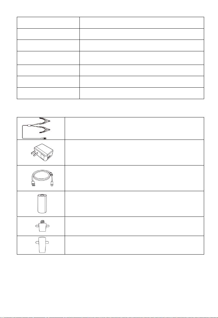
2.3 Other Accessories
Battery Clamp Cable
Connects tester to battery
Power Adapter
Together with the USB cable, connects the unit to an
external DC power port for power supply.
USB Cable
Together with the power adapter, connects the unit to an
external DC power port for power supply.
Paper Roll (2pcs)
Used for thermal printer to print out reports
Battery Side Post Terminal Type S (2 pcs) (optional)
Connects the battery posts and the clamps
Battery Side Post Terminal Type T (2 pcs) (optional)
Connects the battery posts and the clamps
Supply Current
150 mA @ 12 V DC
Operating Temperature
-10°C to 50°C (14 ° F to 122 ° F)
Storage Temperature
-40°C to 80°C (-40 ° F to 176 ° F)
Dimensions (L x W x H)
89.89 mm (3.53”) x 46.78 mm (1.84”) x 21 mm
(0.82”)
Weight
70.7 g (0.156 lb.)
Built-in Battery
3.7 V Lithium Battery
Light
White LED
10
Getting Started
Ensure the unit is sufficiently charged.
NOTE
The images and illustrations depicted in this manual may differ from the ones in
your tool.
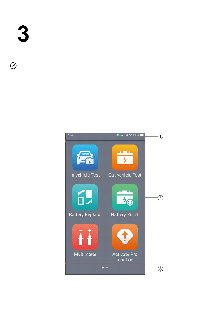
3.1 Power Up
Press and hold the Lock/Power button on the left side of the tester to switch
the unit on. The system will boot up and display the Main Menu.
Figure 3-1 Sample OTOFIX BT1 Tester Main Menu
11
1. Status Bar
2. Application Buttons
3. Page Indicator
3.1.1 Page Indicator and System Status Bar
Descriptions of icons on the status bar and page indicator are displayed
below (Table 3-1).
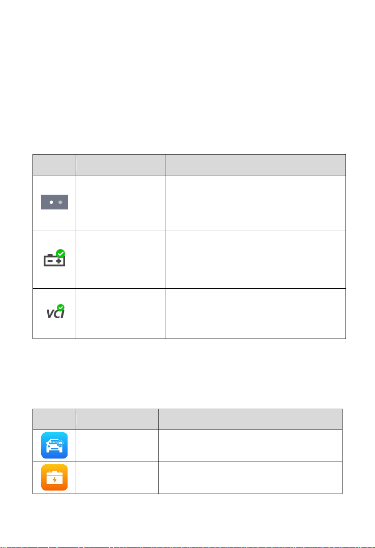
Table 3-1 System Status Icons and Page Indicator
Icon
Name
Description
Page Indicator
Indicates the position of the current page in
a list of pages. The user swipes the screen
left or right to view the previous or next
page.
Battery Connection
A green check mark at the top right corner
indicates the tool is connected to the
battery, while a red X icon indicates there is
no connection.
VCI Connection
Green check mark at the top right corner
indicates the VCI device is connected, while
a red X indicates there is no connection.
3.1.2 Application Buttons
Descriptions of the application buttons are displayed below (Table 3-2).
Table 3-2 Applications
Button
Name
Description
In-vehicle Test
Tests batteries that are installed in a vehicle.
See In-vehicle Test on page 16.
Out-vehicle Test
Tests batteries that are not connected to a
vehicle. See Out-vehicle Test on page 25.
12
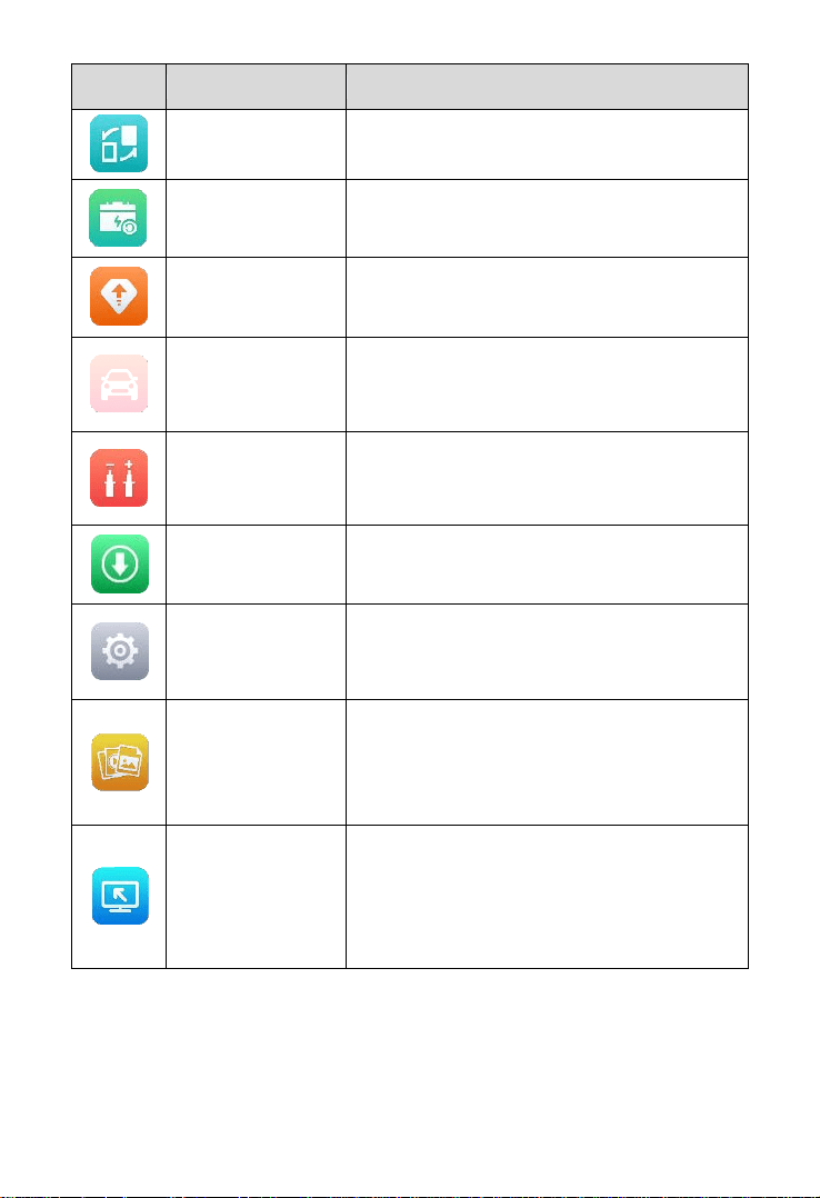
Button
Name
Description
Battery Replace
Operation guide for battery replacement.
See Battery Replace on page 27.
Battery Reset
Accesses the Battery Reset function.
See Battery Reset on page 29.
Activate
Pro Function
Purchases Diagnostics function.
See Activate Pro Function on page 33.
(subscription only)
Diagnostics
Only displays with valid subscription.
Reads and/or erases trouble codes.
See Diagnostics on page 33.
Multimeter
Accesses the Multimeter function. (The
multimeter is sold separately.)
See Multimeter on page 40.
Update
Accesses system software update menu.
See Update on page 46.
Settings
Accesses the VCI Manager, BAS Manager,
System Settings Menu, and more.
See Settings on page 48.
Data Manager
Accesses the saved repair shop, customer,
and vehicle data including detailed vehicle
diagnostics and test records.
See Data Manager on page 49.
Remote Desktop
Remotely controls the device from any
computer or even from another mobile
device. Transfers files from the device to a
computer, or vice versa.
See Remote Desktop on page 52.
13
3.1.3 Drop-down Menu
Swipe down from the top of the screen to access the drop-down menu. Here,
users can quickly change some of the most commonly-used settings and
functions with a tap. Descriptions of these buttons are displayed below (Table
3-3).
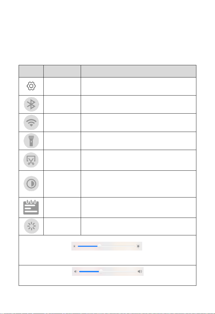
Table 3-3 Drop-down Menu Buttons
Button
Name
Description
Settings
Quick access to the Settings function.
Bluetooth
Enables Bluetooth connection.
Wi-Fi
Enables Wi-Fi connection.
Flashlight
Turns on/off the flashlight.
Screenshot
Captures a screenshot of the current screen.
Auto
Brightness
Adjusts the screen brightness automatically.
Logger
Accesses the Log Collection function.
Restart
Restarts the application.
Screen Brightness Slider — Slides to manually adjust the screen
brightness.
Volume Slider — Slides to manually adjust the volume.

14
3.2 Power Off
All vehicle communications should be terminated before shutting down the tester.
A warning message displays if a shutdown is attempted while the tester is
communicating with the vehicle. Forcing a shutdown while the tester is
communicating with the vehicle may lead to ECU problems on some vehicles.
Please exit the Diagnostics application before shutting down the tester.
To power off the tester:
1. Press and hold the Lock/Power button.
2. Tap Power off option.
3. Tap OK.
Reboot System
In case of system crash, press and hold the Lock/Power button and tap Restart
to reboot the system.
3.3 Test Preparation
3.3.1 Inspecting the Battery
Before starting a test, inspect the battery for:
Cracking, buckling or leaking (If you see any of these defects, replace
the battery.)
Corroded, loose or damaged cables and connections (Repair or replace
as needed.)
Corrosion on the battery terminals, and dirt or acid on the case top
(Clean the case and terminals using a wire brush and a mixture of water
and baking soda.)
3.3.2 Connecting to a Battery
1. Connect the clamp cable to the clamp cable port on the tool and tighten
the connector of the clamp cable. Press and hold the Lock/Power
button to turn on the OTOFIX BT1. Select the desired function and
follow the on-screen instructions.
15
2. Connect the red clamp to the positive (+) terminal and the black clamp
to the negative (−) terminal of the battery.
16
In-vehicle Test
In-vehicle Test is used for testing batteries that are installed in a vehicle. An in-
vehicle test includes battery test, starter test, and generator test. These tests
help determine the health status of the battery, the starter, and the generator.
IMPORTANT
A Disclaimer page will appear when accessing any function on the Home screen
for the first time. Please read the end user agreement and TAP Accept to
continue. If you tap Decline, you will not be able to use the features properly.
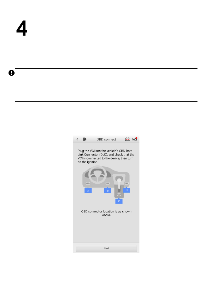
4.1 Start the Test
Select In-vehicle Test on the Home Screen. An illustration displays the OBDII
connector location.
Figure 4-1 Sample In-vehicle Test Home Screen
17
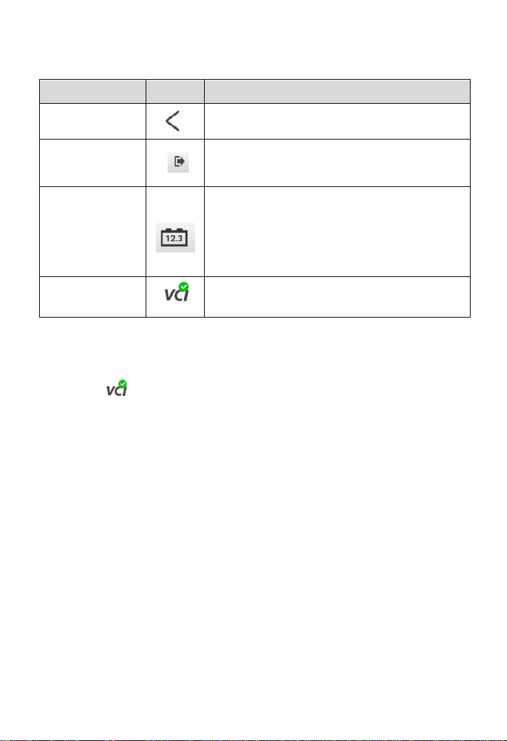
Buttons
Table 4-1 Upper Toolbar Buttons
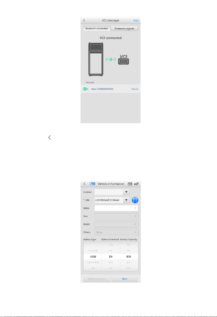
4.1.1 VCI Connection
1. Connect the VCI to the vehicle’s OBD Data Link Connector (DLC).
2. Tap the icon on the top right corner to enter the VCI Manager menu. The
device will automatically enable Bluetooth and start searching for available
pairing units.
3. The device name will appear on this menu as “Maxi” suffixed with a serial
number.
4. Check the serial number on your VCI label and select the desired device for
pairing.
5. When paired successfully, the connection status is shown as Paired and the
vehicle/connection LED will light solid blue.
Name
Button
Description
Back
Returns to the previous screen
Home
Returns to the Home Screen
Battery
Connection
Displays the battery connection status. The
number on the icon indicates the real-time
voltage of the tested battery. In the battery test,
the button will turn green if the battery is good;
otherwise, it will turn red.
VCI
Connection
Tap to enter the VCI Manager. The icon also
displays the connection status of the VCI.
18
Figure 4-2 Sample VCI Manager Screen
6. Tap the icon to return to the previous screen. The tab will move to the
Vehicle information screen. The VCI button on the top right corner of the
screen displays a green check mark, indicating the tester is connected to
the VCI.
4.1.2 Confirm Vehicle Information
Figure 4-3 Sample Vehicle Information Screen
19
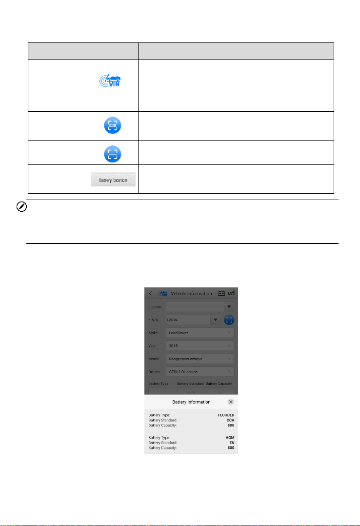
Buttons
NOTE
The Scan License feature is supported in limited countries and regions. Please
manually enter the license numbers if it is not available.
7. The vehicle information will be automatically identified when vehicle
communication is established. The Battery Information tab will display from
the bottom of the screen.
Figure 4-4 Sample Battery Information Screen
Name
Button
Description
AutoVIN
After the VCI is connected to the device through
the vehicle’s OBD Data Link Connector (DLC),
turn on the ignition. The vehicle’s VIN number
will automatically be recognized.
Scan
License
Tap to scan license plate.
Scan VIN
Tap to scan Vehicle Identification Number (VIN).
Battery
Location
Tap to check the battery location diagram.
20
8. Tap the icon on the tab to return to the Vehicle information screen. Tap
Battery Location on the bottom left corner of the screen and review the
battery location diagram.
9. Locate the battery, check the battery information on it, and select the correct
battery parameters on the screen.
10. Confirm the information on the Vehicle information screen. Tap the
corresponding field to manually input the correct parameters if needed. Tap
Next to continue.
4.2 Battery Test
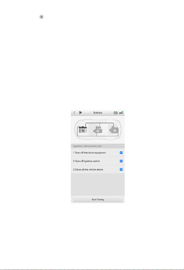
11. The Clamp Connection Diagram will appear. Follow the instructions to
connect the clamp cables correctly and tap Next to continue.
Figure 4-5 Sample Battery Screen
12. Follow the on-screen instructions, check the boxes once listed tasks are
completed, and tap Start Testing.
13. Wait until the test is completed. The test results will be displayed on the tool.
21
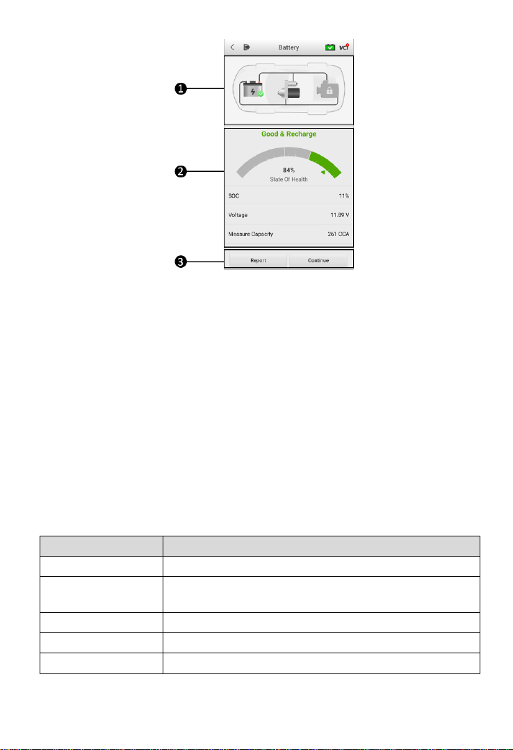
Figure 4-6 Sample Battery Test Result Screen
1. Process Buttons
2. Test Report
3. Function Buttons
Process Buttons
Tap any of the process buttons to advance to the corresponding test — battery
test, starter test or generator test. A status icon will display on the bottom right
corner of the button, indicating the test results.
Battery Test Results
The battery test results include a color-coded result summary, a list of test data,
and repair tips.
Table 4-2 Test Results
Result
Repair Tip
Good Battery
Battery is good.
Good & Recharge
Battery is good but insufficiently charged. Recharge the
battery.
Charge & Retest
Battery requires charge to determine its condition.
Bad Cell
Replace the battery.
Replace Battery
Replace the battery.
22
Function Buttons
The Function Buttons at the bottom of the screen vary depending on the
operation. Functions include Report and Replace Battery. The table below
provides a brief description of the Function Buttons operations:
NOTE
Please always complete the battery test before you proceed to the starter and
generator tests.
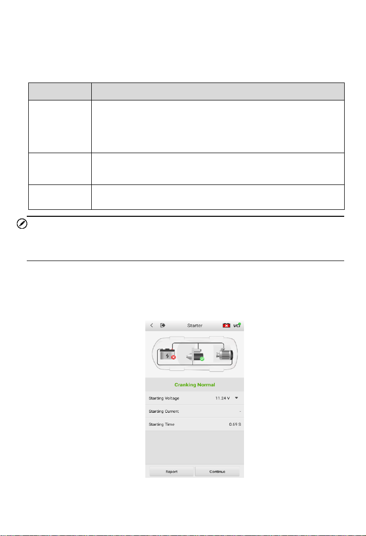
4.3 Starter Test
14. Follow the on-screen instructions to complete the test. Start the engine and
let it idle. The test results will display as follows:
Figure 4-7 Sample Starter Test Result Screen
Name
Description
Report
Tap to view the test data and results in report form. Tap Print
on the bottom of the screen to print the test report to the built-
in thermal printer. Tap Email to send the test report to an email
address.
Replace
Battery
Tap to continue to replace the battery.
See Battery Replace on Page 27.
Continue
Tap to perform the next test.
23
Table 4-3 Starter Test Results
Result
Description
Cranking Normal
The starter is good
Current Too Low
Low momentary discharge capacity
Voltage Too Low
Low battery storage capacity
Not Started
The starter is not detected for starting
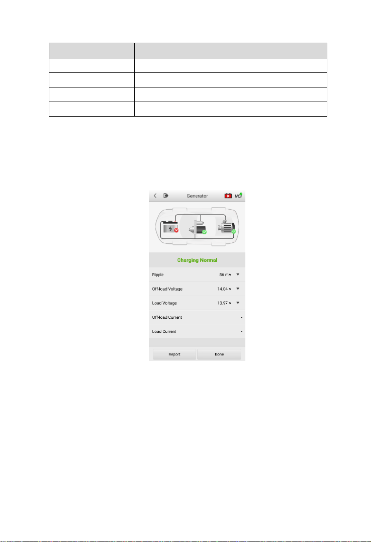
4.4 Generator Test
15. Follow the on-screen instructions to complete the test. The test results will
display as follows:
Figure 4-8 Sample Generator Test Result Screen

24
Table 4-4 Generator Test Results
Result
Description
Charging Normal
The generator is good.
Output Too Low
The belt linking the starter and the
generator is loose;
The cable linking the starter and
battery is loose or corroded.
Output Too High
The generator is not properly
connected to the ground;
The voltage adjuster is broken and
needs replacement.
Ripple Too Large
The commutation diode is broken.
No Output
The cable is loose;
Some vehicles with power
management systems do not
provide path for charging due to the
sufficient load capacity of the
battery;
The generator or the voltage
adjuster is broken and needs
replacement.
NOTE
To measure the current, connect the current clamp. Tap the Settings button on
the main menu to enter the application. Swipe the Current Clamp toggle to turn
it ON.
25
Out-Vehicle Test
Out-vehicle Test is used to test the condition of batteries that are not connected
to a vehicle. This function aims to check the health status of the battery only.
The compatible battery types and standards are as follows:
Types: FLOODED, AGM, AGM SPIRAL, EFB, and GEL
Standards: CCA, SAE, CA, EN, EN2, IEC, DIN, JIS, MCA, BCI, and GB
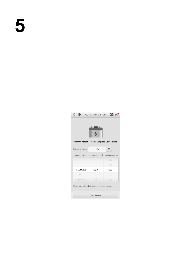
5.1 Test Procedure
1. Connect the tester clamps to the battery terminals.
2. Select the appropriate battery type, rating standard, and CCA value. Tap
Start Testing to start the test.
Figure 5-1 Sample Out-vehicle Test Screen
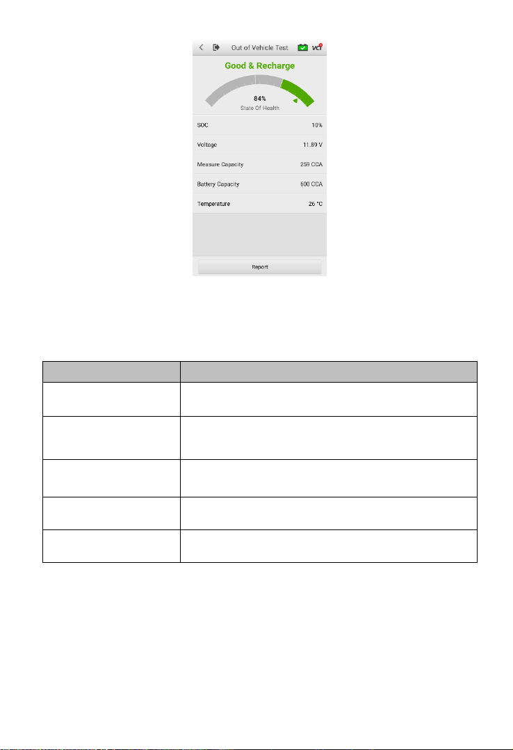
3. The test results will display in a few seconds.
26
Figure 5-2 Sample Out-vehicle Test Results Screen
5.2 Test Results
Icons are color-coded to indicate status.
Result
Description
Good Battery
Battery meets required standards.
Good & Recharge
Battery is good, but low on charge. Fully charge
the battery. Check for causes of low charge.
Charge & Retest
Battery requires charge to determine its condition.
Replace Battery
Battery fails to meet industry-accepted standards.
Bad Cell
Battery fails to meet industry-accepted standards.
27
Battery Replace
The Battery Replace function guides you to replace the battery step by step. The
battery replacement process includes Battery Type Suggestion, Preparation,
Battery Replacement steps, New Battery Test and Battery Registration.
To replace the battery:
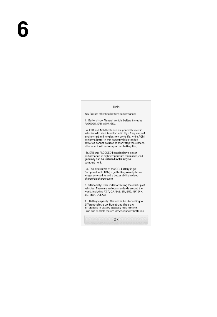
1. Tap the Help button at the bottom of each screen to read all the help
information carefully before operation, then follow the on-screen
instructions to complete the battery replacement.
Figure 6-1 Sample Help Screen
2. To save the vehicle’s onboard data when the vehicle’s battery is
removed or disconnected, it is recommended to use a memory saver
(optional accessory) to connect a spare battery to the vehicle.
28
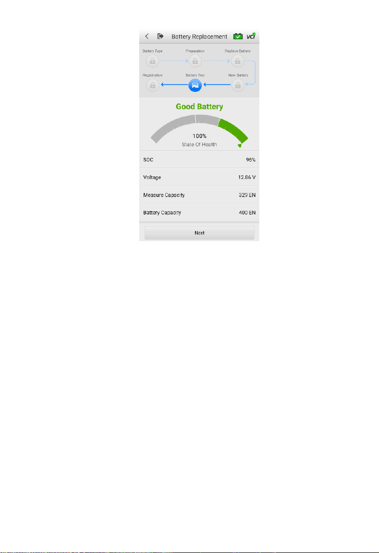
Figure 6-2 Sample New Battery Test Results Screen
3. When the new battery test is completed, tap Next to automatically
proceed to Auto Registration in the Battery Reset section.
29
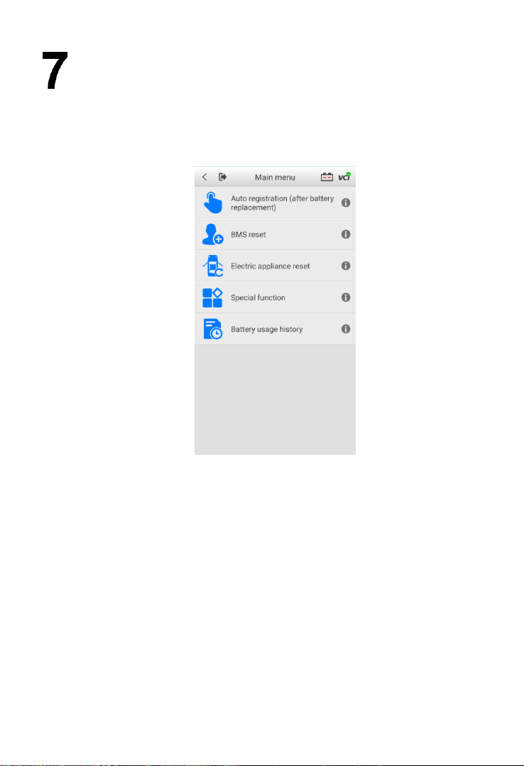
Battery Reset
The Battery Reset allows users to access the following functions: Auto
registration (after battery replacement), BMS reset, Electric appliance reset,
Special function and Battery usage history.
Figure 7-1 Sample Battery Reset Main Menu Screen
7.1 Auto Registration (after battery replacement)
Auto registration is often used after the successful installation of a new battery,
including BMS reset and Electric appliance reset.
7.1.1 BMS Reset
The BMS reset feature enables you to register a new battery after battery
replacement. The BMS Reset function varies by vehicle make. Please follow
the on-screen instructions to perform the desired functions.

30
Figure 7-2 Sample BMS Reset Menu Screen
After choosing the desired battery replacement registration, information of
Scene, Condition, Influence and Note will display. Click Next to complete
registration.
7.1.2 Electric Appliance Reset
When the vehicle power is interrupted in order to replace the battery, and a
memory saver has not been used, position settings on some vehicle
components will be lost. These settings should be relearned. The functions
and related operations in Electric appliance reset vary by vehicle make.
Please follow the on-screen instructions to perform the desired functions.
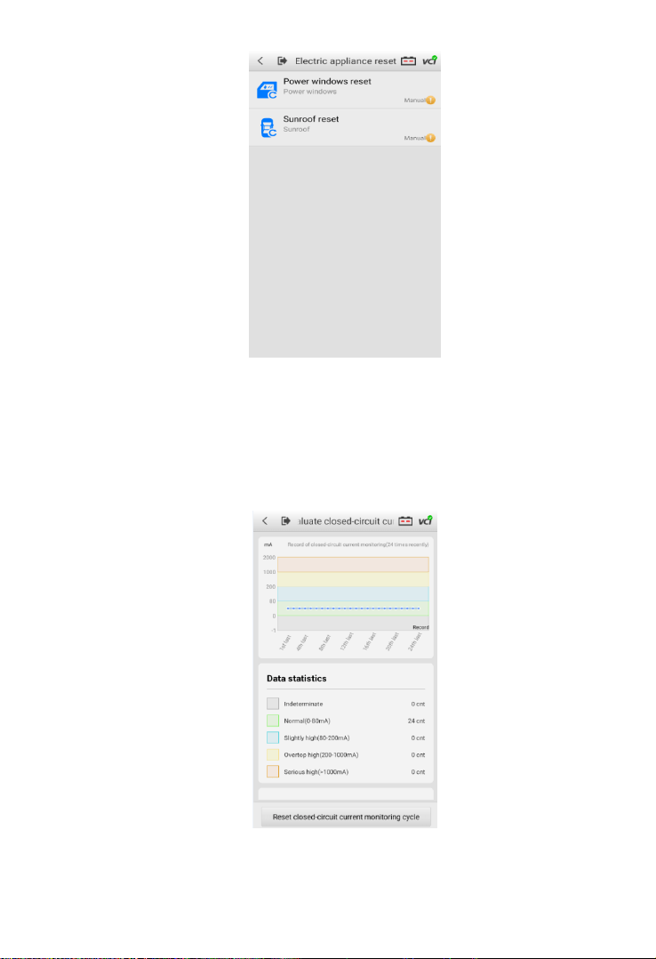
31
Figure 7-3 Sample Electric Appliance Reset Screen
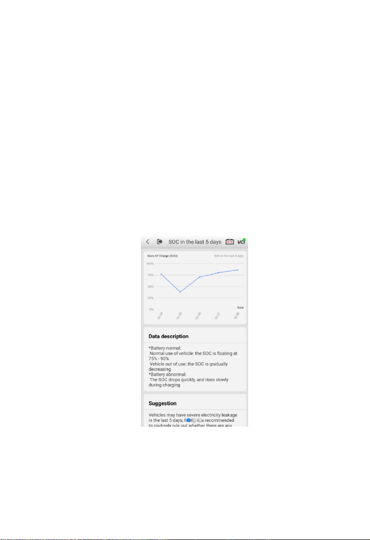
7.2 Special Function
The special function varies by vehicle make. Functions other than battery
reset are categorized as special functions. Please follow the on-screen
instructions to perform the desired function.
Figure 7-4 Sample Reset Closed-circuit Current Monitoring Cycle Screen
(BMW vehicles)
32
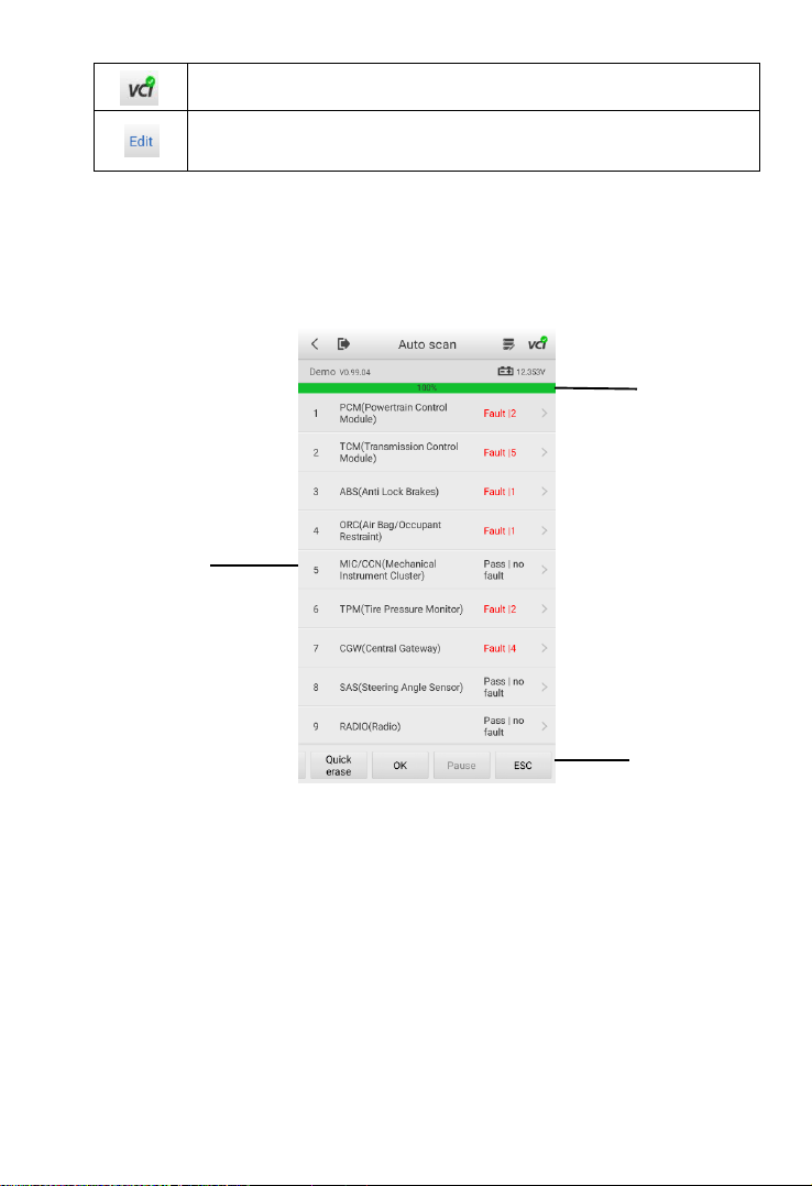
7.3 Battery Usage History (only for BMW
vehicles)
The Battery usage history function will display the following three tests:
1. SOC (State of Charge) in the last 5 days: monitors the SOC status and
diagnoses the health status of the battery.
2. Proportion of SOC duration: displays battery usage habits of drivers.
3. Estimated current mileage comparison (battery replacement):
determines the current battery life based on the previous vehicle mileage
record.
All three test screens are comprised of three sections:
1. Main view: displays data in a waveform or bar graph.
2. Data description: provides brief descriptions of the test result.
3. Suggestion: offers suggestions on existing problems.
Figure 7-5 Sample SOC in the Last 5 Days Screen

33
Diagnostics (subscription only)
NOTE
The Diagnostics function can only be accessed with a valid subscription.
To subscribe to the Diagnostics function:
1. Go to Activate Pro Function on the Home screen.
2. Read Note of Successful Upgrade carefully before tapping the Upgrade
button.
3. Detailed information (including the expenses, order number, item, and expiry
date) of your order will display on the screen. Then, select a payment method
and tap Confirm Purchase to complete your order.
The Diagnostics function enables all systems fault detection, and access to live
system data for numerous vehicle control systems, such as engine, transmission,
and ABS.
After choosing a diagnostic type (Automatic selection or Manual selection) on the
Diagnostics main menu, there are two options available when accessing the
Diagnosis menu:
1. Auto Scan — starts scanning all available systems on the vehicle.
2. Control Units — displays a selection menu for all available control units of
the vehicle.
After a section is made and the tester establishes communication with the vehicle
via the VCI, the corresponding function menu or selection menu will display.
Table 8-1 Top Toolbar Buttons
Button
Description
Return to the previous page.
Return to the Home Screen.
Start and stop data recording.
34
Display VCI connection.
Choose live data parameters by selecting appropriate
checkbox. (Available on Live data screen)
8.1 Auto Scan
The Auto scan function performs a comprehensive scan of all the ECUs in the
vehicle to detect faults and retrieve DTCs.
Figure 8-1 Sample Auto Scan Operation Screen
1. Progress Percentage — indicates the test progress
2. Main Section
3. Function Buttons
Main Section
Column 1 — displays the sequence numbers.
Column 2 — displays the scanned systems.
Column 3 — displays the diagnostic indicators describing test results.

35
The indicators are defined as follows:
Fault | #: Fault indicates detection of fault code(s); # indicates the quantity of
detected faults.
Pass | no fault: indicates the system has completed the scanning process with
no fault detected.
Column 4 — to perform further diagnosis or testing on a specific system item,
tap the arrow button to the right of that item to display the Function menu screen.
Function Buttons
A brief description of the operations of the Auto Scan Function Buttons are
displayed in the table below.
Table 8-2 Auto Scan Function Buttons
Name
Description
Save
Saves the scanning results as a PDF document.
Report
Displays the diagnostic data in report form.
Quick
Erase
Deletes codes. A warning message will display to alert user of
possible data loss when this function is selected.
OK
Confirms the test results. Continues with the system diagnosis
after the desired system is selected by tapping the item in the
Main Section.
Pause
Suspends scanning. Tap Continue to resume.
ESC
Returns to the previous screen or exits Auto Scan.
8.2 Control Units
Select to directly locate a desired control system for testing. Follow the menu-
driven procedures and make proper selection; the application guides the user to
the proper diagnostic function menu based on these selections.

36
Figure 8-2 Sample Function Menu Screen
The Function menu options may vary by vehicle. The Function menu may include:
ECU information
Read codes
Erase codes
Live data
Freeze frame
To perform a diagnostic function:
1. Establish communication with the test vehicle.
2. Identify the vehicle by selecting from the menu options.
3. Select the Diagnostics section.
4. Locate a system for testing by Auto Scan or through menu-driven
selections in Control Units.
5. Select a diagnostic function from the Function menu.
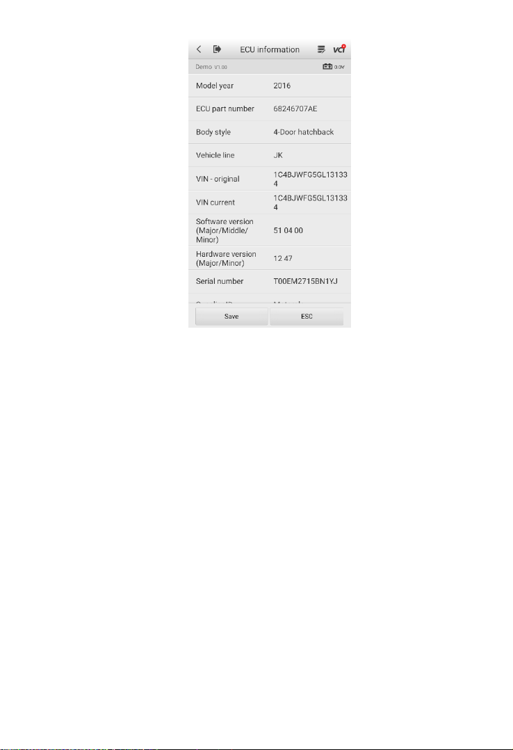
8.2.1 ECU Information
This function retrieves and displays the specific information for the tested
control unit, including model year, and ECU part number.
37
Figure 8-3 Sample ECU Information Screen
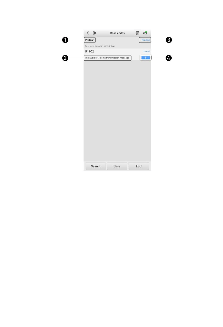
8.2.2 Read Codes
This function retrieves and displays the DTCs from the vehicle’s control
system. The Read codes screen varies by each vehicle model being tested.
The availability of freeze frame data for viewing varies by vehicle.
38
Figure 8-4 Sample Read Codes Screen
Main Section
1. Code section — displays the retrieved codes from the vehicle.
2. Description section — describes the retrieved codes in detail.
3. Status section — indicates the status of the retrieved codes.
4. Snowflake icon — indicates freeze frame data is available for viewing.
Selecting this icon will display a data screen, which looks and functions
similar to the Read codes screen.
8.2.3 Erase Codes
After reading the retrieved codes from the vehicle and completing repairs,
use this function to erase the codes from the vehicle. Before performing this
function, make sure the vehicle’s ignition key is in the ON (RUN) position with
the engine off.

39
To erase codes:
1. Tap Erase codes on the Function menu.
2. A message warning that DTCs and/or freeze frame data will be deleted
will display:
b) Tap Yes to continue. A confirmation screen will display when the
operation is successful.
c) Tap No to exit.
3. Tap ESC on the confirmation screen to exit Erase codes.
4. Return to the Function menu and tap Read codes to verify.

40
Multimeter
The multimeter (sold separately) is a multi-function, multi-range measuring
instrument. Connect the multimeter to the OTOFIX BT1 and access its
application directly from the home screen to perform AC/DC voltage, AC/DC
current, and resistance measurements, and diode, and connectivity tests. The
test results will be displayed in number or graph.
9.1 Safety Information
Follow the instructions below to reduce the risk of injury from electric shock and
prevent equipment damage.
Use the multimeter only as specified in this manual.
Do not apply more than the rated voltage between connectors or between
any connector and ground.
Do not input a value beyond the maximum range when measuring.
Remember that the maximum range of this multimeter is 200V.
To prevent injury or death, do not use the multimeter if it appears to be
damaged in any way, and stop use immediately if you are concerned with
any abnormal operations.
To prevent injury or death, never ground yourself when taking electrical
measurements. Isolate yourself from ground by using dry rubber insulating
mats to cover all exposed/grounded metal. Ensure all clothing including
gloves are dry. Stand on rubber mats when using tool.
Use the test leads or probes supplied with the product, or compatible
terminals. Inspect the test leads or probes for damage before use.
When using probes, keep fingers behind the finger guards on the probes.
Use the supplied replacement fuses or specified replacement parts.
Always consider electrical and electronic equipment to be energized (live).
Never assume any equipment is de-energized.
When making electrical connections, connect the common test lead before
connecting the live test lead; when disconnecting, disconnect the live test
lead before disconnecting the common test lead.
When measuring current, turn off circuit power before connecting the
multimeter to the circuit. Remember to place the multimeter in series with

41
the circuit.
After current measurement is finished, turn off the power to the circuit before
removing the test leads and before reconnecting any disconnected wires or
devices.
Do not add voltage to the input terminal when measuring resistance.
To avoid electric shock, turn off the power to the component before
connecting.
To prevent damage, always use and store your multimeter in appropriate
environments.
Do not use in wet or damp conditions, or around explosive gas or vapor.
Do not tamper with or disassemble the multimeter, connectors or
accessories. Internal damage will affect performance.
Before carrying out maintenance and cleaning of the multimeter, make sure
the unit is NOT connected to a power source, vehicle or computer.
When cleaning the multimeter, use a damp, soft cloth with mild detergent.
Do not allow water to enter the multimeter casing.
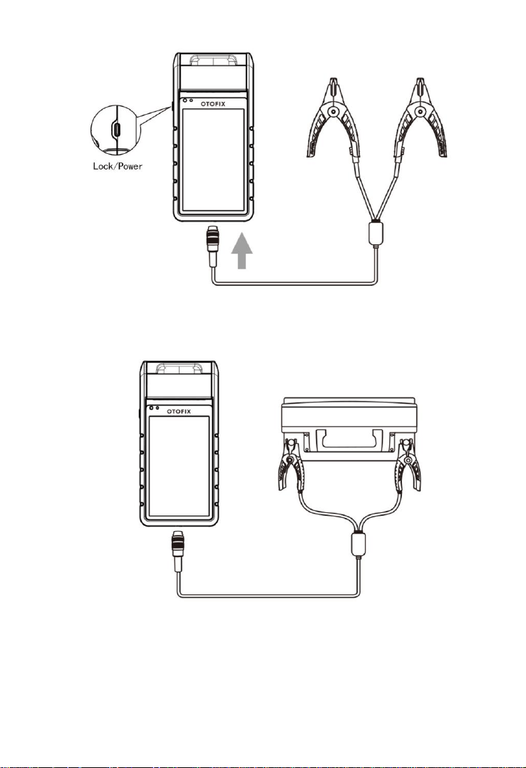
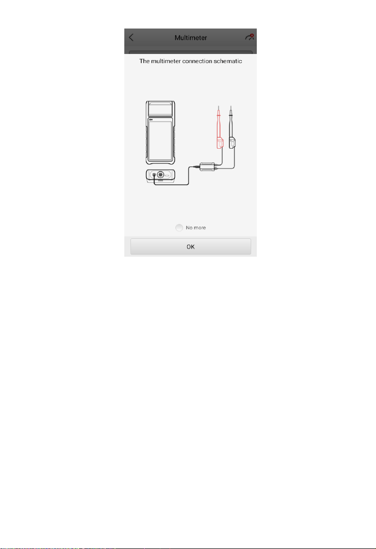
9.2 Getting Started
Before opening the Multimeter application, ensure the multimeter device is
connected to the tester via the multimeter cable (see diagram below). Tap no
more to hide diagram.
The device will beep when successfully connected with the tester.
42
Figure 9-1 Sample Multimeter Connection Schematic
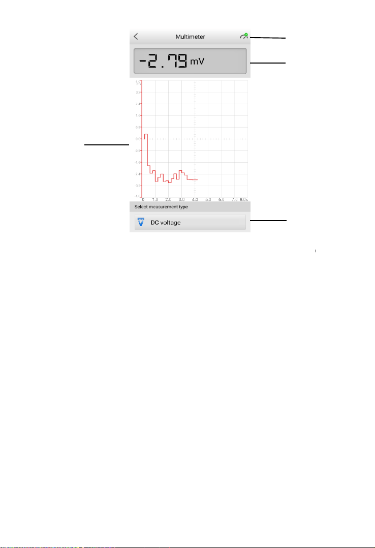
9.3 Screen Layout and Operation
Tap the Multimeter icon on the main menu to view the multimeter page.
43
Figure 9-2 Sample Multimeter Test Screen
1. Multimeter icon
2. Digital display
3. Main view section
4. Measurement type selection
9.3.1 Multimeter Icon
The Multimeter status icon indicates the connection status with the tester. A
green check mark means that the tester and the multimeter are connected; a
red “X” means that the device and the tester are not connected.
9.3.2 Digital Display
This section displays the digital measurement results.
9.3.3 Main View Section
The main view section features a coordinate grid with the X-axis representing
the time duration and the Y-axis representing the amplitude level.
①
②
④
44
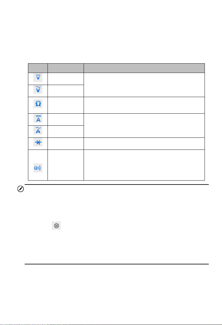
9.3.4 Measurement Type Selection
This multimeter can be used to measure AC voltage, DC voltage, resistance,
AC electricity, DC electricity, diode, and connectivity.
The measurement types include:
Icon
Name
Description
AC voltage
Measures the voltage in the electrical circuit.
DC voltage
Resistance
Measures the resistance of the electrical circuit
or the component.
AC current
Measures current amperage by using the
optional current clamp.
DC current
Diode
Conducts a diode test of the electrical circuit.
Connectivity
Determines whether a low impedance exits two
points in the electrical circuit. If the impedance is
less than 100 ohms, the circuit is “closed”,
otherwise, the circuit is “open”.
NOTE
1. AC/DC current is measured with clamps, while AC/DC voltage, diode
and connectivity are measured with probes.
2. When selecting the Resistance measurement type, the self-calibration
mark will display after Resistance, indicating the multimeter will
return to zero in order to improve accuracy.
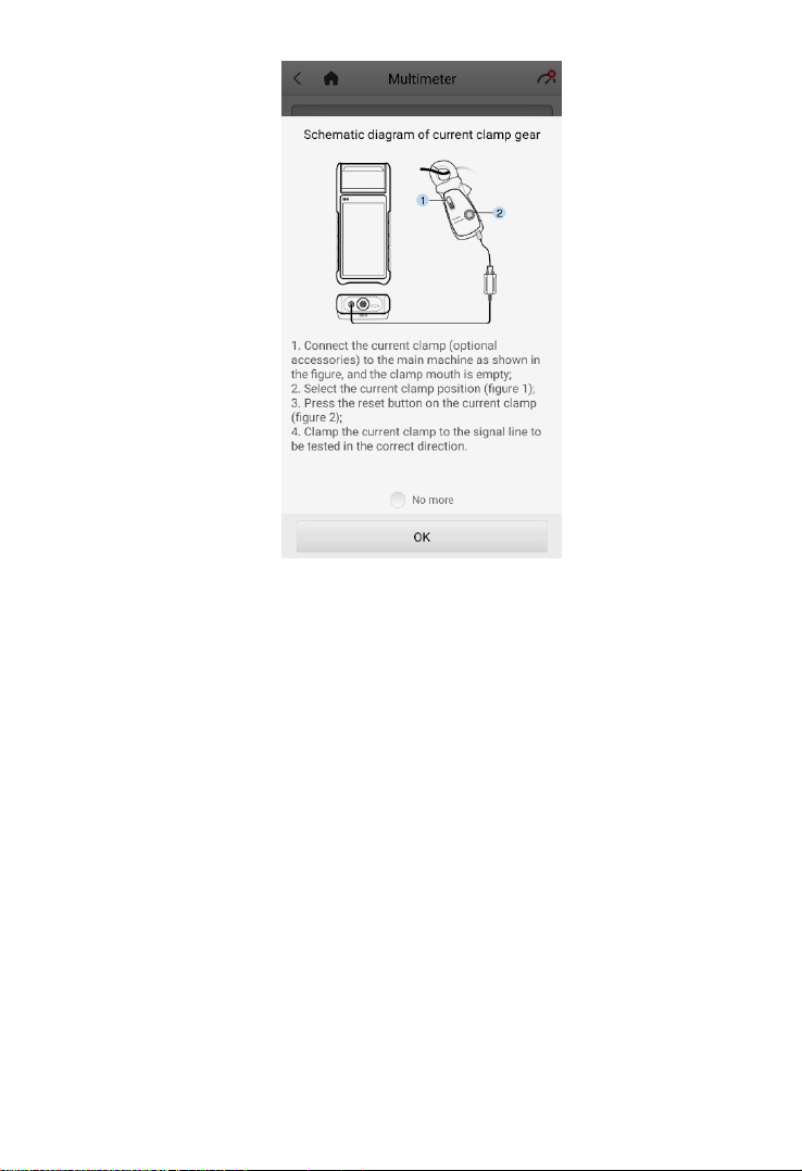
3. When measuring AC/DC current, different measuring ranges require
different operations of the clamp (see Figure 9-3). Tap no more to hide
diagram.
45
Figure 9-3 Sample Schematic Diagram of Current Clamp
46
Update
This function allows you to update your OTOFIX BT1 software through Wi-Fi
connection, including software for operating system, applications, battery testing,
battery registration, and vehicle manufacturers. A notification displays when
updates are available. Ensure the tool is connected to a stable Wi-Fi network and
follow the on-screen instructions to update software.
Tap into any available vehicle software to view vehicle model coverage. Updates
for previously-installed software may display information regarding improved
diagnostics and service functions.
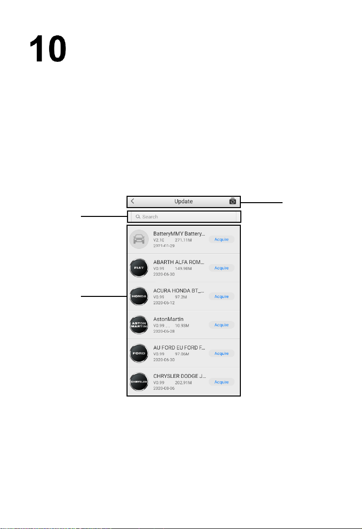
Figure 10-1 Sample Update Main Screen
1. Upper Toolbar
2. Search Bar
3. Main Section

47
Upper Toolbar
Button
Description
Returns to the previous page.
Tap to acquire all software.
Search Bar
Searches for updates by vehicle manufacturer.
Main Section
Left Column — displays vehicle logos.
Middle Column — displays the newest software version for update and
information of the size and release date of the update package.
Right Column — buttons vary by the operation.
a) Tap Acquire to download and install the desired software.
b) Tap the button to suspend the updating procedure.
c) Tap Paused to continue updating.

48
Settings
Access the Settings menu to adjust default settings and view information about
the OTOFIX BT1 system.
Option
Description
VCI manager
VCI Manager is for connecting the OTOFIX BT1 with
a VCI device via Bluetooth. This option allows you to
pair the tester with the VCI device, check the
communication status, and upgrade the VCI firmware.
BAS manager
Allows you to check and update the firmware version
and resources.
System settings
Sets and adjusts the Wi-Fi connection, language, date
and time, display and sound, sleep mode, cache
clearing, and factory reset.
About
Displays information about the OTOFIX BT1, including
device serial number, password, system version,
hardware version, APP version, BAS version, BAS
firmware version, VCI firmware, VCI software, and
capacity.
Unit
Selects the units of measure system. Choose between
Metric and Imperial units.
Current clamp
Swipe the Current clamp toggle to enable current
measurement.
49
Data Manager
The Data Manager application allows you to store, print, and review the saved
files, manage workshop information and customer information records, and keep
test vehicle history records. There are six main functions available.
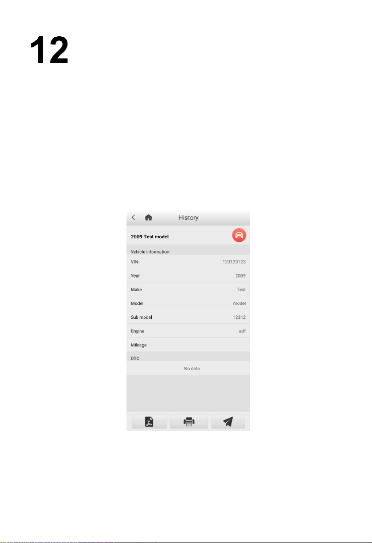
12.1 Test Records
This option stores records of test vehicle history, including battery tests and
diagnostics. The diagnostics records also provide direct access to the previously-
tested vehicle and allow you to directly restart a diagnostic session without the
need to perform vehicle selection.
Figure 12-1 Sample Diagnostics Test Records Screen

50
12.2 Workshop Information
The Workshop Information form allows you to input, edit, and save detailed
workshop information, such as shop name, address, phone number, and other
remarks, which, when printing vehicle diagnostics reports and other associated
test files, will display as the header of the printed reports.
12.3 Image
The Image option is a JPG database containing all captured screenshots. Tap
the icon on the top right corner of the screen to delete the selected images.
12.4 PDF
The PDF option stores and displays all PDF files of saved data. After entering
the PDF database, select a PDF file to view the stored information. Tap the “…”
multi-function icon on the top right corner of the screen to share the files or print
them out on your PC.
12.5 Uninstall Apps
This option allows you to manage the firmware applications installed on the
Diagnostics System. Selecting this option opens a management screen, on
which you can check all available vehicle diagnostic applications.
Select the vehicle firmware you want to delete, tap the Delete button on the
bottom of the screen to delete the firmware from the system database.
12.6 Data Logging
The Data Logging option allows you to launch the Support platform to view all
records on the diagnostic system. The Data Logging option keeps records of all
Feedback (submitted), Not Feedback (not submitted but saved) or History (up
to the latest 20 test records) data loggings on the diagnostic system. You can
edit and send test records by using the Data logging function. OTOFIX support
personnel will receive and process submitted reports through the Support
platform.

51
NOTE
Thermal Paper
The internal printer is shipped with two rolls of thermal paper (2.3’’ wide by 0.98’’
in diameter). Replacement rolls are available in most stationery stores.
To replace the paper roll:
1. Open the cover of the printer by gently lifting it upwards.
2. Remove the spent roll if any.
3. Insert a new paper roll.
4. Pull the paper out past the cutter at the front of the printer. While doing so,
make sure that the paper roll stays taut and doesn’t unroll.
5. Push the cover down to snap it closed. For a clean tear, pull the paper along
the serrated edge.
52
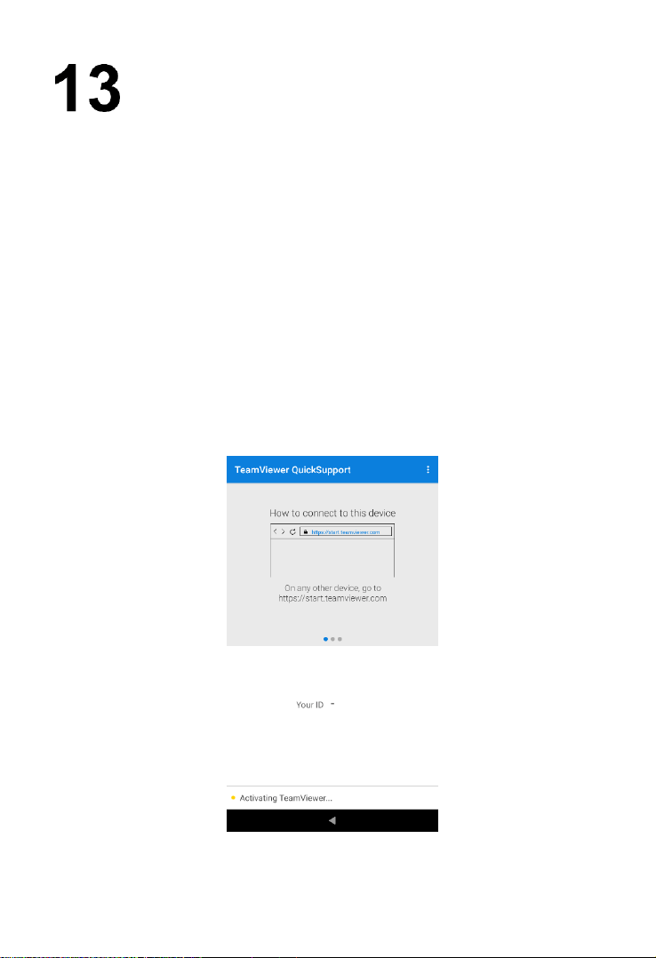
Remote Desktop
The Remote Desktop application launches the TeamViewer Quick Support
program, which is a simple, fast, and secure remote-control interface. You can
use the application to receive remote support from OTOFIX support center,
colleagues or friends by allowing them to control your OTOFIX BT1 tester on
their PC via the TeamViewer software.
If you think of a TeamViewer connection as a phone call, the TeamViewer ID
would be the phone number under which all TeamViewer Clients can be reached
separately. Computers and mobile devices that run TeamViewer are identified
by a unique global ID. The first time the Remote Desktop application is launched,
this ID is generated automatically based on the hardware characteristics of the
tester. The user cannot change the ID.
Make sure the tester is connected to the Internet before launching the Remote
Desktop application, so that the OTOFIX BT1 is able to receive remote support
from the third party.
Figure 13-1 Sample TeamViewer Interface Screen

53
To receive remote support from a partner:
1. Power on the OTOFIX BT1.
2. Tap the Remote Desktop application from the Main Menu. The
TeamViewer interface appears and the device ID is generated and
shown.
3. Your partner must install the Remote Control software to his/her
computer by downloading the TeamViewer program (full version)
online (http://www.teamviewer.com). Start the software on his/her
computer at the same time in order to provide support and take
control of the OTOFIX BT1 remotely.
4. Provide your ID to the partner and have them to send you a remote
control request.
5. A prompt will appear asking you to allow remote control on your
device.
6. Tap Allow to accept or Deny to reject.
Refer to the associated TeamViewer documents for additional information.

54
Register Tool
To update the software on your tool, the tool must be registered. The installation
of the latest firmware and vehicle software is vital to the successful operation of
the BT1. Register the tool and download the software prior to using. Register
directly on the tool or via Internet on a mobile device or computer.
14.1 Registration via Tester
1. First, make sure the device is connected to Wi-Fi.
2. The device will automatically detect whether the user has registered; if not,
a dialog box will display asking the user to register the tool.
3. Tap OK to view the sign-in screen.
4. Create an Autel ID using a readily accessible email address.
5. Enter your email address and password, and tap Verification code. Check
your email for the verification code. Enter the code and tap Sign up.
6. The serial number and password fields will be filled automatically. Tap
REGISTER.
14.2 Registration via an Internet Browser on a
Computer or Mobile Device
1. Visit http://pro.otofixtech.com/.
2. If you already have an Autel account, sign In with your account ID and
password; if you are a new member to Autel, click on the Create Autel ID
button on the screen to create an ID.
3. The online system will send a verification code to the registered email
address. Input the code in the Verification code field and complete the
other required fields. Read through Autel’s Terms and Conditions and
click on Agree. Click Create Autel ID to continue. A product registration
screen will display.
4. Check the device’s serial number and password from the Settings > About screen.
5. Select your product model, enter the product serial number and password
on the Product Registration screen, and click Submit to complete the
registration procedure.

55
Maintenance and Service
To ensure that the tester and the combined VCI unit perform at their optimum
level, we advise that the product maintenance instructions covered in this section
are read and followed.
15.1 Maintenance Instructions
The following shows how to maintain your devices, together with precautions to
take.
Use a soft cloth and alcohol or a mild window cleaner to clean the touch
screen of the tester.
Do not use any abrasive cleansers, detergent, or automotive chemicals on
the tester.
Maintain the devices in dry conditions and keep them within normal
operating temperatures.
Dry your hands before using the tester. The touchscreen of the tester may
not work if the touch screen is moist, or if you tap the touch screen with wet
hands.
Do not store the devices in humid, dusty or dirty areas.
Check the housing, wiring, and connectors for dirt and damage before and
after each use.
At the end of each work day, wipe the device housing, wiring, and
connectors clean with a damp cloth.
Do not attempt to disassemble the tester or the VCI unit.
Do not drop or cause severe impact to the devices.
Use only authorized battery chargers and accessories. Any malfunction or
damage caused by the use of unauthorized battery charger and
accessories will void the limited product warranty.
Ensure that the battery charger does not come in contact with conductive
objects.
Do not use the tester beside microwave ovens, cordless phones and some
medical or scientific instruments to prevent signal interference.

56
15.2 Troubleshooting Checklist
A. When the tester does not work properly:
Make sure the tester has been registered online.
Make sure the system software and diagnostic application software are
properly updated.
Make sure the tester is connected to the Internet.
Check all cables, connections, and indicators to ensure the signal is being
received.
B. When battery life is shorter than usual:
This may happen when you are in an area with low signal strength. Turn off
your device if not in use.
C. When you cannot turn on the tester:
Make sure the tester is connected to a power source or the battery is
charged.
D. When you are unable to charge the tester:
Your charger maybe out of order. Contact your local distributor for
assistance.
You may be attempting to use the device in an overly hot/cold temperature.
Charge the device in a cooler or warmer area.
Your device may have not been connected to the charger properly. Check
the connector.
NOTE
If the problems persist, please contact OTOFIX technical support personnel or
your local distributor.
15.3 About Battery Usage
Your tester is powered by a built-in Lithium-ion Polymer battery. This means that,
unlike other forms of battery technology, you can recharge your battery while
some charge remains without reducing your tester’s autonomy due to the “battery
memory effect” inherent in those technologies.

57
1. The built-in Lithium-ion Polymer battery is factory replaceable only;
incorrect replacement or tampering with the battery pack may cause an
explosion.
2. Do not use a damaged battery charger.
Do not disassemble or open, crush, bend or deform, puncture or shred.
Do not modify or remanufacture, attempt to insert foreign objects into the
battery, expose to fire, explosion or other hazards.
Make sure to use the charger and USB cables that come together in the
package only. If you use the other charger and USB cables, you might
incur malfunction or failure of the device.
Only use the charging device that has been qualified with device per the
standard. Use of an unqualified battery or charger may present a risk of
fire, explosion, leakage, or other hazards.
Avoid dropping the tester. If the tester is dropped, especially on a hard
surface, and the user suspects damage, contact support.
The battery recharging time varies depending on the remaining battery
capacity.
Battery life inevitably shortens over time.
Since over charging may shorten battery life, remove the tester from its
charger once it is fully charged. Unplug the charger once charging is
complete.
Leaving the tester in hot or cold places, especially inside a car in summer
or winter, may reduce the capacity and life of the battery. Always keep
the battery within normal temperatures.
15.4 Service Procedures
This section introduces information for technical support, repair service, and
application for replacement or optional parts.
15.4.1 Technical Support
If you have any question or problem on the operation of the product, please
contact us.
OTOFIX NORTH AMERICA
Email: [email protected]
DANGER

58
Web: www.otofixtech.com
Phone: (833) 686-1349 (OTO-1FIX) (Monday-Friday 9am-6pm EST)
Address: 175 Central Avenue, Suite 200, Farmingdale, New York, USA
11735
OTOFIX CHINA HQ
Email: [email protected]
Website: www.otofix.cn
Phone: 0086-755-2267-2493 (Monday-Friday, 9:00AM-6:00PM Beijing
Time)
Address: 7th, 8th and 10th floor, Building B1, Zhiyuan, Xueyuan Road,
Xili, Nanshan, Shenzhen, 518055, China
For technical assistance in other markets, please contact your local
distributor.
15.4.2 Repair Service
If it becomes necessary to return your device for repair, please download the
repair service form from www.otofixtech.com, and fill in the form. The
following information must be included:
Contact name
Return address
Telephone number
Product name
Complete description of the problem
Proof-of-purchase for warranty repairs
Preferred method of payment for non-warranty repairs
NOTE
For non-warranty repairs, payment can be made with Visa, Master Card, or
with approved credit terms.
Send the device to your local distributor, or to the below address:
7th, 8th and 10th Floor, Building B1, Zhiyuan, Xueyuan Road, Xili, Nanshan,
Shenzhen, 518055, China

59
16 Compliance Information
FCC Compliance FCC ID: WQ8BATSTB2022
WQ8BATSTBV200
This device complies with part 15 of the FCC Rules. Operation is subject to the
following two conditions:
a) This device may not cause harmful interference, and
b) This device must accept any interference received, including
interference that may cause undesired operation.
WARNING
Changes or modifications not expressly approved by the party responsible for
compliance could void the user’s authority to operate the equipment.
NOTE
This equipment has been tested and found to comply with the limits for a Class
B digital device, pursuant to Part 15 of the FCC Rules. These limits are designed
to provide reasonable protection against harmful interference in a residential
installation.
This equipment generates uses and can radiate radio frequency energy and, if
not installed and used in accordance with the instructions, may cause harmful
interference to radio communications. However, there is no guarantee that
interference will not occur in a particular installation. If this equipment does
cause harmful interference to radio or television reception, which can be
determined by turning the equipment off and on, the user is encouraged to try
to correct the interference by one or more of the following measures:
-- Reorient or relocate the receiving antenna.
-- Increase the separation between the equipment and receiver.
-- Connect the equipment into an outlet on a circuit different from that to which
the receiver is connected.
-- Consult the dealer or an experienced radio/TV technician for help.

60
SAR
The radiated output power of this device is below the FCC radio frequency
exposure limits. Nevertheless, the device should be used in such a manner that
the potential for human contact is minimized during normal operation.
The exposure standard for wireless devices employs a unit of measurement
known as the Specific Absorption Rate, or SAR. The SAR limit set by the FCC is
1.6 W/Kg. Tests for SAR are conducted using standard operating positions
accepted by the FCC with the device transmitting at its highest certified power
level in all tested frequency bands.
Although the SAR is determined at the highest certified power level, the actual
SAR level of the device while operating can be well below the maximum value.
This is because the device is designed to operate at multiple power levels so as
to use only the power required to reach the network. To avoid the possibility of
exceeding the FCC radio frequency exposure limits, human proximity to antenna
should be minimized.
FCC Radiation Exposure Statement
This equipment complies with FCC radiation exposure limits set forth for an
uncontrolled environment. This equipment should be installed and operated with
minimum distance 20cm between the radiator & your body.
CE COMPLIANCE
This product is declared to conform to the essential requirements of the following
Directives and carries the CE mark accordingly:
EMC ETSI EN 301 489-1 V2.2.3(2019-11)
ETSI EN 301 489-17 V3.1.1(2017-02)
EN 55032: 2015
EN 55035: 2017
Safety EN 62368-1: 2014+A11: 2017
Health EN 50566: 2017
EN 62479: 2010
EN 62209-2: 2010
Radio ETSI EN 300 328 V2.2.2 (2019-07)
ETSI EN 300 440 V2.2.1 (2018-07)
ETSI EN 301 893 V2.1.1 (2017-05)

61
17 Warranty
17.1 Limited One Year Warranty
Autel Intelligent Technology Corp., Ltd. (the Company) warrants to the
original retail purchaser of this OTOFIX BT1 that should this product or any
part thereof during normal usage and under normal conditions be proven
defective in material or workmanship and results in product failure within 1
year period from the date of purchase, such defect(s) will be repaired, or
replaced (with new or rebuilt parts) with Proof of Purchase, at the Company’s
option, without charge for parts or labor directly related to the defect(s).
The Company shall not be liable for any incidental or consequential damages
arising from the use, misuse, or mounting of the device. Some states do not
allow limitation on how long an implied warranty lasts, so the above
limitations may not apply to you.
This warranty does not apply to:
1) Products subjected to abnormal use or conditions, accident,
mishandling, neglect, unauthorized alteration, misuse, improper
installation or repair or improper storage;
2) Products whose mechanical serial number or electronic serial number
has been removed, altered or defaced;
3) Damage from exposure to excessive temperatures or extreme
environmental conditions;
4) Damage resulting from connection to, or use of any accessory or other
product not approved or authorized by the Company;
5) Defects in appearance, cosmetic, decorative or structural items such as
framing and non-operative parts.
6) Products damaged from external causes such as fire, dirt, sand, battery
leakage, blown fuse, theft or improper usage of any electrical source.

62
IMPORTANT
All contents of the product may be deleted during the process of repair. You
should create a back-up copy of any contents of your product before
delivering the product for warranty service.