aFTX
NUMBER 917.376360
®
OWNER'S MANUAL
• Assembly
• Operation
• Customer
Responsibilities
• Service
• Adjustments
• Repair Parts
Caution:
Read and Follow
all Safety Rules
and Instructions
Before Operating
This Equipment
153306 12.14.95 ks
IIIIIIIIIII
II
Printed in LLS.A,
illl_i
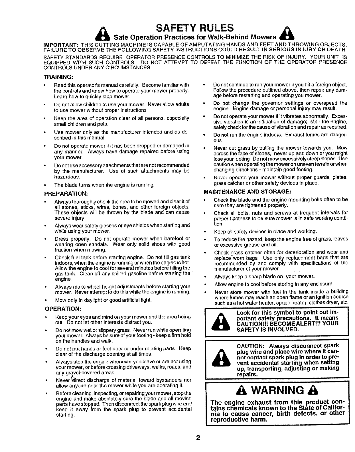
SAFETY RULES
_k Safe Operation Practices for Walk-Behind Mowers
IMPORTANT: THIS CUTTING MACHINE IS CAPABLE OF AMPUTATING HANDS AND FEET AND THROWING OBJECTS_
FAILURE TO OBSERVE THE FOLLOWING SAFETY INSTRUCTIONS COULD RESULT IN SERIOUS INJURY OR DEATH
SAFETY STANDARDS REQUIRE OPERATOR PRESENCE CONTROLS TO MINIMIZE THE RiSK OF INJURY, YOUR UNIT IS
EQUIPPED WITH SUCH CONTROLS: DO NOT ATTEMPT TO DEFEAT THE FUNCTION OF THE OPERATOR PRESENCE
CONTROLS UNDER ANY CIRCUMSTANCES
TRAINING:
• Read this operator's manual carefully. Become familiar with
the controls and know how to operate your mower properiyo
Learn how to quickly stop mower.
• Do not allow children to use your mower Never aUow adults
to use mower without proper instructions
• Keep the area of operation clear of all persons, especially
small children and pets.
• Use mower only as the manufacturer intended and as de-
scribed in this manual.
• Do not operate mower if it has been dropped or damaged in
any manner._ Always have damage repaired before using
your mower.
• Do not use accessory attachments that are not recommended
by the manufacturer.. Use of such attachments may be
hazardous
• The blade turns when the engine is running.
PREPARATION:
• Always thoroughly check the area to be mowed and clear itof
all stones, sticks, wires, bones, and other foreign objects.
These objects will be thrown by the blade and can cause
severe injury.
• Always wear safety glasses or eye shields when starting and
while using your mower
• Dress properly. Do not operate mower when barefoot or
wearing open sandals. Wear only solid shoes with good
traction when mowing.
, Check fuel tank before starting engine Do not fill gas tank
indoors, when the engine isrunning or when the engine is hot
Allow the engine to cool for several minutes before filling the
gas tank. Clean off any spilled gasoline before starting the
engine
- Always make wheel height adjustments before starting your
mower. Never attempt to do this while the engine is running.
• Mow only in daylight or good artificial light.
OPERATION:
• Keep your eyes and mind on your mower and the area being
cut Do not let other interests distract you
• Do not mow wet or slippery grass. Never run while operating
your mower. Always be sure of your footing - keep a firm hold
on the handles and walk
• Do not put hands or feet near or under rotating parts. Keep
clear of the discharge opening at all times_
• Always stop the engine whenever you leave or are not using
your mower, orbefore crossing driveways, walks, roads, and
any gravel-covered areas
• Never _irect discharge of material toward bystanders nor
allow anyone near the mower while you are operating it.
° Before cleaning, inspecting, orrepairing your mower, stop the
engine and make absolutely sure the blade and all moving
parts have stopped. Then disconnect the spark plug wire and
keep it away from the spark plug to prevent accidental
starting°
• Do not continue to run your mower ifyou hit a foreign object..
Follow the procedure outlined above, then repair any dam-
age before restarting and operating you mower.
• Do not change the governor settings or overspeed the
engine Engine damage or personal injury may result.
• Do not operate your mower if it vibrates abnormally Exces-
sive vibration is an indication of damage; stop the engine,
safelycheck for the cause of vibration and repair as required.
• Do net runthe engine indoors. Exhaust fumes are danger-
ous.
• Never cut grass by pulling the mower towards you.. Mow
across the face of slopes, never up and down or you might
lose your footing.. Do not mowexcessivelysteepslopeso Use
caution when operatingthe mower on uneven terrain orwhen
changing directions - maintain good footing°
• Never operate your mower without proper guards, plates,
grass catcher or other safety devices in place..
MAINTENANCE AND STORAGE:
• Check the blade and the engine mounting bolts often to be
sure they are tightened pmpedy.
= Check all bolts, nuts and screws at frequent intervals for
proper tightness to be sure mower is in safe working condi-
tion.
° Keep all safety devices in place and working,.
• To reduce fire hazard, keep the engine free ofgrass, leaves
or excessive grease and oil
• Check grass catcher often for deterioration and wear and
replace worn bags_ Use only replacement bags that are
recommended by and comply with specifications of the
manufacturer of your mower......
• Always keep a sharp blade on your mower°
• Altow engine to cool before storing in any enclosure..
° Never store mower with fuel in the tank inside a building
where fumes may reach an open flame or an ignition source
such as a hot water heater, space heater, clothes dryer, etc.
..................... HH= =HHH |
Look for this symbol to point out im-
I
portant safety precautions. It means
CAUTION!!! BECOME ALERT!!! YOUR
SAFETY' IS INVOLVED.
== = H =IH =
.................................. H= ,H,,
CAUTION; Always disconnect spark
plug wire and place wire where it can-
not contact spark plug in order to pre-
vent accidental starting when setting
up, transporting, adjusting or making
repairs.
................... H= HH==
H HHH=
A WARNING A
The engine exhaust from this product con-
tains chemicals known to the State of Califor-
nia to cause cancer, birth defects, or other
reproductive harm.
===l= HHH,= = IH
C()NGRATULATIONS on your purchase of a Sears Lawn
Mower. It has been designed, engineered and manufac-
tured to give you the best possible dependability and
performance_
Should you experience any problem you cannot easily
remedy, please contact your nearest Sears Authorized
Service Center/DepartmenL We have competent, well-
trained technicians and the proper tools to service or repair
this lawn mower,.
Please read and retain this manual. The instructions will
enable you to assemble and maintain, your lawn mower
properly. Always observe the "SAFETY RULES".
MODEL
NUMBER 917_376360
SERIAL
NUMBER
DATEOFPURCHASE
THE MODELAND SERIAL NUMBERSWILLBE FOUND
ON A DECAL ATTACHED TO THE REAR OF THE
LAWN MOWER HOUSING
YOUSHOULDRECORDBOTHSERIALNUMBERAND
DATE OF PURCHASE AND KEEP IN A SAFE PLACE
FOR FUTURE REFERENCE
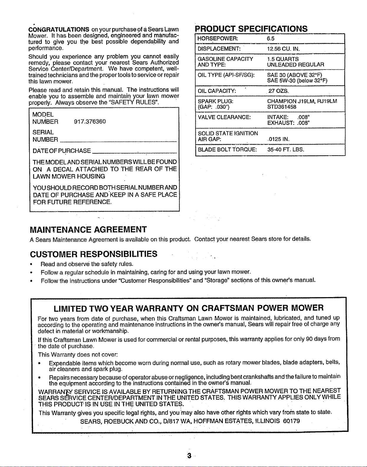
pRODUCT SPECIFICATIONS
HORSEPOWER: 6,5
DISPLACEMENT: 1236 CUoIN.
GASOLINE CAPACITY 1o5QUARTS
AND TYPE: UNLEADED REGULAR
OIL TYPE (API-SF/SG): SAE 30 (ABOVE 32°F)
SAE 5W_30(below 32°F)
OIL CAPACITY: 27 OZS.
SPARK PLUG: CHAMPION J19LM, RJ19LM
(GAP: °030") STD36!458
VALVE CLEARANCE: INTAKE: ,008"
EXHAUST: .008"
SOLID STATE IGNITION
AIR GAP: o0125INo
BLADE BOLTTORQUE: 35_40 FT. LBS.
i
MAINTENANCE AGREEMENT
A Sears Maintenance Agreement isavailable on this producL Contact your nearest Sears store for details.
CUSTOMER RESPONSIBILITIES -
• Read and observe the safety rules.
• Follow a regular schedule in maintaining, caring for and using your fawn mower,
• Follow the instructions under "Customer Responsibilities" and =Storage" sections of this owner's manual.
LIMITED TWO YEAR WARRANTY ON CRAFTSMAN POWER MOWER
For two years from date of purchase, when this Craftsman Lawn Mower is maintained, lubricated, and tuned up
according to the operating and maintenance instructions in the owner's manual, Sears will repair free of charge any
defect in material or workmanship.
If:this Craftsman Lawn Mower is used for commercial or rental purposes, this warranty applies for only 90 days from
the date of purchaser
This Warranty does net cover:
. Expendable items which become worn during normal use, such as rotary mower blades, blade adapters, belts,
air cleaners and spark plug.
• Repairs necessary because of operator abuse or negligence, including bent crankshafts and the failure to maintain
the equipment according to the instructions contained in the owner's manual.
WARRAN'_ SERVICE IS AVAILABLE BY RETURNING THE CRAFTSMAN POWER MOWER TO THE NEAREST
SEARS SERVICE CENTER/DEPARTMENT IN THE UNITED STATES_ THIS WARRANTY APPLIES ONLY WHILE
THIS PRODUCT" IS IN USE IN TH E UNITED STATES,
This Warranty gives you specific legal rights, and you'may also have Other rights which vary fror:n state to state,
SEARS, ROEBUCK AND CO., D/817 WA, HOFFMAN ESTATES ILLINOIS 60179
i ii iiiiiiiiiiiiiiiii
3
SAFETY RULES ................. ........................................... 2
PRODUCT SPECIFICATIONS ...................................... 3
CUSTOMER RESPONSIBILITIES .............. ....... 3, 12-14
WARRANTY .................................................................. 3
ASSEMBLY ................................................................... 6
OPERATION ................. _................................................ 8
MAINTENANCE SCHEDULE ..................................... 12
SERVICE AND ADJUSTMENTS ................................ 15
STORAGE ................................................................... 16
TROUBLESHOOTING ................................................. 17
REPAIR PARTS - LAWN MOWER ........................ 18-23
REPAIR PARTS - ENGINE .................................... 25-27
PARTS ORDERING/SERVICE ................................ ;.. 28
INDEX
A
Accessories .........................................5
Adjustments:
Carburetor. ............................. 15
Drive Belt ........................ _...... 15
Engine Speed ........................ 15
Handle Height ......................... 15
Height of Cut ............................... 9
Air Filter:
Replacement ...............:............ 14
Service .................................... 14
Assembly ................................... ,...... 6
B
Blade:
Sharpening ................. ;........... 13
Replacement ............;................ 13
C
Controls:
Drive Control ............................ 8
Engine Zone Control ................ 8
Engine Speed Control......oo:,:, 8
Operator' Presence
Control Bar ............................... 8
Customer Responsibilities ... 3, 12-14
Air Filter .................................. 14
Blade Care!Replacement ....... 13
Drive Wheels .......................... 13
Engine ..........................................14
Lubrication ............................. :f4
Spark Plug ............................. 14
Cutting Levels .................................... 9
E
Engine:
Air Filter ........................................14
Oil Change ................................ 14
Oil Level ................................... 14
Oil Type .......,.......................... 14
Starting ..................................... 10
Stopping .......................................10
Storage ........................................16
F
Fuel:
Capacity ..................._..........................3
Storag_ ........................................i., 16
Type ................................................10
H
Handle Adjustment:
Assembly ......................................6
Cutting Height ............................15
L
Lubrication:
Engine ............i................................14
Lawn Mower. ............................ 12
M
Maintenance Agreement ................ 3
Maintenance Schedule .................. 12
Mowing Tips .................................... 10
Oil:
O
Engine ...............................................12
Sto rage ..................................... 16
Operation:
Ddve Control .............................. g
Engine Control .............................9
Grass Catcher ........................... 9
Mower'. ......................................... 9
Operator Presence
Control Bar ....................................9
Options:
Accessodes .....................................5
R
Repair Parts:
Engine ................................ 25-27
Lawn Mower .............................t8-23
Responsibilities, Customer., 3, 12-14
S
Safety Rules ..................................................2
Service and Adjustments .............. 15
Carburetor ............................... 15
Drive Belt ............................... 15
Engine Speed ,.oo..,o.. .........t--- 15
Handle .........................................15
Spark Plug ........................................ 14
Specifications .......................................3
Speed Control:
Engine ....................................... 8
Starting the Engine ....................... 10
Stopping the Engine ...................... 10
Storage ............................................... 16
T
Trouble Shooting Chart .....................17
W
Warranty ........ _.................................. 3
4
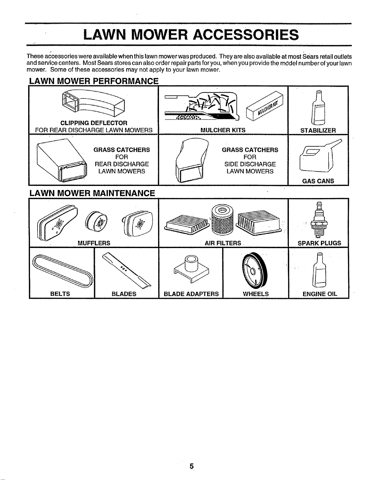
These accessories were available when this lawn mower was produced° They are also available at most Sears retail outlets
and service centers. Most Sears stores can also order repair parts for you, when you provide the model number of your lawn
mower° Some of these accessories may not apply to your lawn mower.
LAWN MOWER PERFORMANCE
CLIPPING DEFLECTOR
FOR REAR DISCHARGE LAWN MOWERS
GRASS CATCHERS
FOR
REAR DISCHARGE
LAWN MOWERS
LAWN MOWER MAINTENANCE
MUFFLERS
MULCHER KITS
J
I
GRASS CATCHERS
FOR
SIDE DISCHARGE
LAWN MOWERS
STABILIZER
GAS CANS
SPARK PLUGS
BELTS BLADES BLADE ADAPTERS WHEELS
ENGINE OIL
5
iiinrn nil nllnnnnl iil,,,nrn n u _
ASSEMBLY
,,,nnlnl inlnnl n l i
Read these instructions and this manual in its entirety
before you attempt to assemble or operate your new lawn
mower Your new lawn mower has been assembled at the
factory with the exception of those parts left unassembled
for shipping purposes All parts such as nuts, washers,
bolts, etc, necessary to complete the assembly have been
placed in the parts bag. To ensure safe and proper
operation of your lawn mower, al_parts and hardware you
assemble must be tightened securely. Use the correct
tools as necessary to ensure proper tightness
TO REMOVE LAWN MOWER FROM
CARTON
• Remove loose parts included with mower°
• Cut down two end comers of carton and lay end panel
down ftaL
• Remove all pactdng materials except padding between
upper and lower handle and padding holding operator
presence control bar to upper' handle. •
= Roll lawn mower out of carton and check carton thor-
oughly for additional loose parts',,
HoWTO SET UPYOUR LAWN MOWER
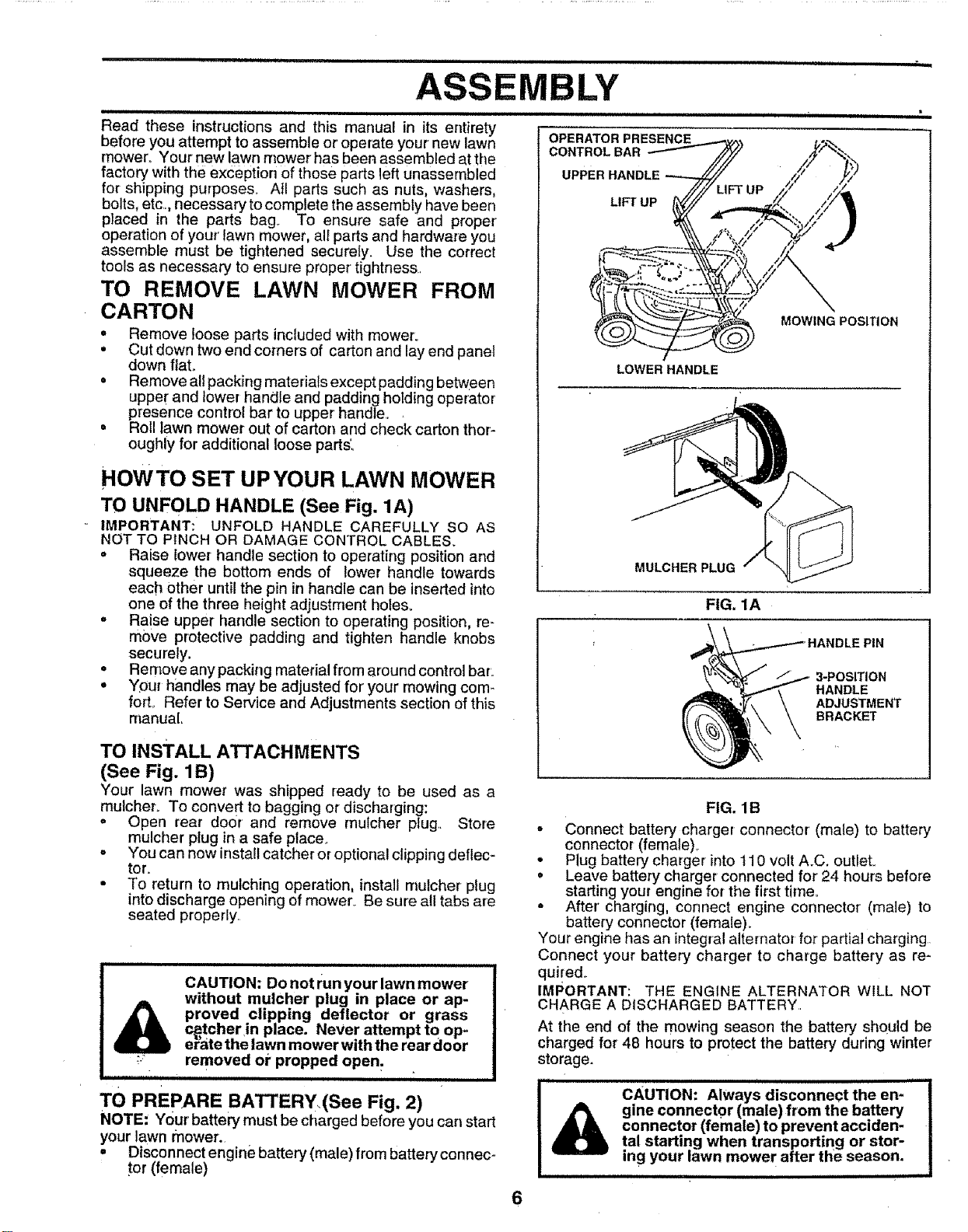
TO UNFOLD HANDLE (See Fig. 1A)
IMPORTANT: UNFOLD HANDLE CAREFULLY SO AS
NOT TO PINCH OR DAMAGE CONTROL CABLES.
" Raise lower handle section to operating position and
squeeze the bottom ends of lower handle towards
each other until the pin in handle can be inserted into
one of the three height adjustment hoies.
. Raise upper handle section to operating position, re-
move protective padding and tighten handle knobs
securely.
. Remove any PaCking material from around control bar,,
• Your handles may be adjusted for your mowing com-
forL Refer to Service and Adjustments section of this
manual
TO INSTALL ATTACHMENTS
(See Fig. 1B)
Your lawn mower was shipped ready to be used as a
mulcher. To convert to bagging or discharging:
. Open rear door and remove mulcher plug,, Store
mulcher plug in a safe place.
. You can now install catcher or optional ciipping deflec-
tor.
• To return to mulching operation, install mutcher plug
into discharge opening of mower Be sure a!l tabs are
seated properly
CAUTION: Do not run your lawn mower
without mulcher plug in place or ap-
proved clipping deflector or grass
c_tcher in place. Never attempt to op-
er"atethe lawn mower with the rear door
removed or propped open.
HIll IIIIIIIIIIIIIII I I ..............
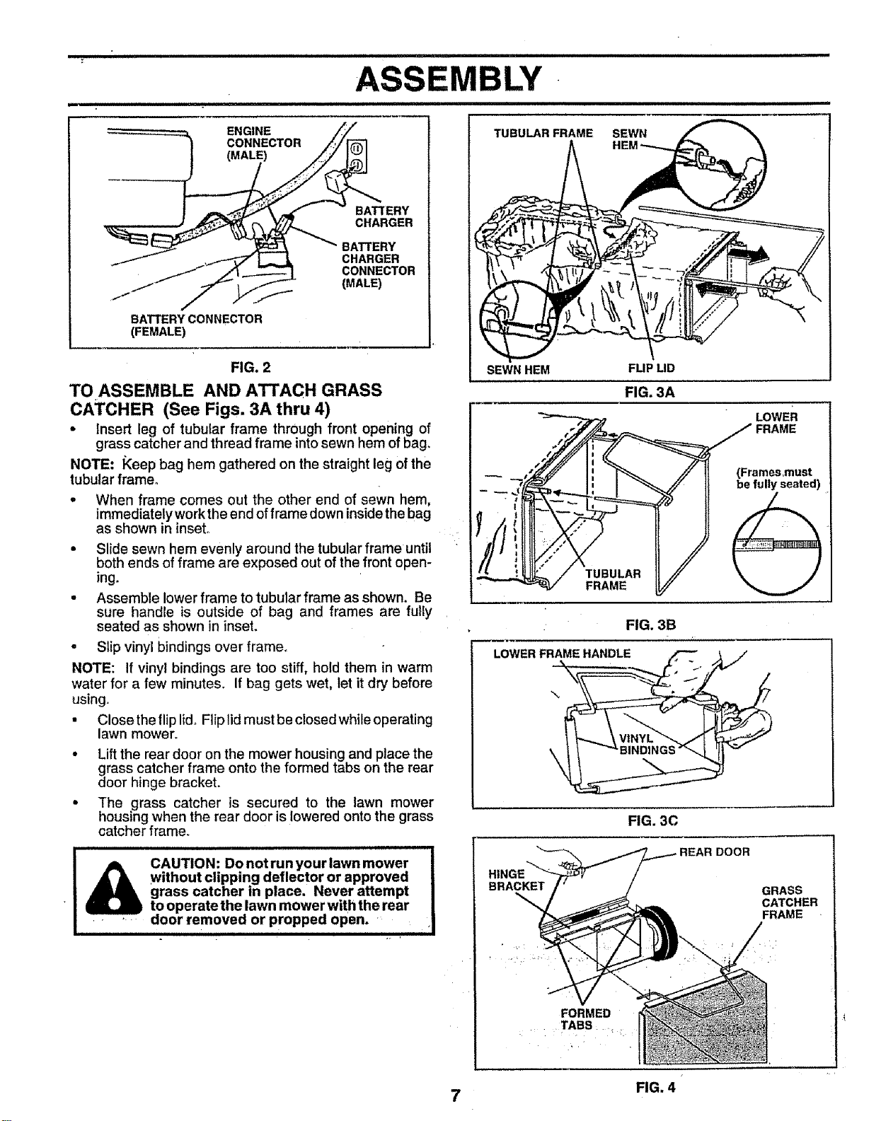
TO PREPARE BATTERY,(See Fig. 2)
NOTE: Your battery must be charged before you can start
your lawn mower.
• Disconnect engine battery (male) from battery connec-
tor (female)
MOWING POSITION
LOWER HANDLE
MULCHER PLUG
FIG. 1A
3-POSITION
HANDLE
ADJUSTMENT
BRACKET
6
FIG. 1B
• Connect battery charger connector (male) to battery
connector (female),
° Plug battery charger into 110 volt A.C, outleL
• Leave battery charger connected for 24 hours before
starting your engine for the first time°
- After charging, connect engine connector (male) to
battery connector (female).
Your engine has an integral alternator for partial charging
Connect your battery charger to charge battery as re-
qui[ed,_
IMPORTANT: THE ENGINE ALTERNATOR WILL NOT
CHARGE A DISCHARGED BATTERY
At the end of the mowing season the battery shQuld be
charged for 48 hours to protect the battery during winter
storage,
1111 innl
CAUTION: Always disconnect the en-
gine connector (male) from the battery
connector (female) to prevent acciden-
tal starting when transporting or stor-
ing your lawn mower after the season.
inll i nl,u irniiii
i i= =1 = iiii i i i = =11i =11=1=1111HH,I=II= ' I I I ,,,,,,,,,,,,,,,, ,,,,,,,,,,,,,,,,', ===1==1=== I
.......................................................... _........ II IIII II I=llllll III
TUBULAR FRAME SEWN
ENGINE
CONNECTOR
(MALE)
BATTERY CONNECTOR
(FEMALE)
BATTERY
CHARGER
BATTERY
CHARGER
CONNECTOR
(MALE)
FIG. 2
TO ASSEMBLE AND ATTACH GRASS
CATCHER (See Figs. 3A thru 4)
o Insert leg of tubular frame thrOugh front opening of
grass catcher and thread frame into sewn hem of bag_
NOTE: I_eep bag hem gathered on the straight leg of the
tubular frame.
- When frame comes out the other end of sewn hem,
immediately work the end of frame down insidethe bag
as shown in inset,r
• Slide sewn hem evenly around the tubular frame until
both ends of frame are exposed out of the front open-
ing.
• Assemble lower frame to tubular frame as shown. Be
sure handle is outside of bag and frames are fully
seated as shown in inset.
• Slip vinyl bindings over frame°
NOTE: If vinyl bindings are too stiff, hold them in warm
water for a few minutes. If bag gets wet, let it dry before
using.
• Close the fliplid. Flip lid must be closed while operating
lawn mower,
• Lift the rear door on the mower housing and place the
grass catcher frame onto the formed tabs on the rear
door hinge bracket.
• The grass catcher is secured to the lawn mower
housing when the rear door is lowered onto the grass
catcher frame.
I A CAUTION: Do not run your lawn mower
I _ • without clipping deflector or approved
i _ grass catcher in place. Never attempt
• I _ to operatethelawn mowerwdh the rear
J .... door removea or proppeo open. •
• ii iiiiiii i'll iiiii i ii i . i i iii iiiiiiiip iiii ii
SEWN HEM FUP LID
FIG. 3B
LOWER FRAME HANDLE
\
J
I
FIG. 30
HII
BRACKET
GRASS
CATCHER
FRAME
FORMED
TABS ....
7 FIG. 4
OPERATION
=,H= ,,,N,,,_,HH=== ,,,,,,,,,,,,,,,,, ,,,,,,=,,,=,H=H= ,,,,H HI HH == ' ========r=== H= "
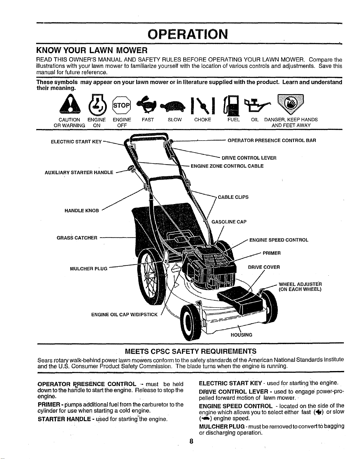
KNOW YOUR LAWN MOWER
READ THIS OWNER'S MANUAL AND SAFETY RULES BEFORE OPERATING YOUR LAWN MOWER, Compare the
illustrations with your lawn mower to familiarize yourself with the location of various controls and adjustments, Save this
manual for' future reference,
,,H, 1111 1111 ,,,11,,,11, 1,,,111111,,,=11 = ,,,,,,iN = ,,,,,,,1,1 = H 1,1HHH ,1
These symbols may appear on your lawn mower orrin literature supplied with the product. Learn and understand
their meaning.
CAUTION ENGINE ENGINE FAST SLOW CHOKE FUEL OIL DANGER, KEEP HANDS
OR WARNING ON OFF AND FEET AWAY
=,,,,,,,Hr ",,HHHHHH= Hi= 'H'H '" I'H, H"H =
ELECTRIC
................. OPERATOR PRESENCECONTROLBAR
AUXILIARY STARTER HANDLE
HANDLE KNOB
GRASS CATCHER
MULCHER PLUG
DRIVECONTROLLEVER
CONTROLCABLE
CABLE CLIPS
GASOL|NECAP
NE SPEED CONTROL
PRIMER
DRIVE COVER
WHEEL ADJ USTE_R
(ON EACH WHEEL)
ENGINE OIL CAP W/DIPSTICK
HOUSING
MEETS CPSC SAFETY REQUIREMENTS
Sears rotary walk-behind power lawn mowers conform to the safety standards of the American National Standards Institute
and the U.So Consumer Product Safety Commission,, The blade turns when the engine is running_
OPERATOR _-_,.ESENCE CONTROL ,- must be held
down to the handle to start the engine. Release to stop the
engine.
PRIMER - pumps additional fuel from the carburetor to the
cylinder for use when starting a cold engine.
STARTER HANDLE ' used for' starting!_the engine°
8
.............;,,, !,,,,,,,,,,,,,,, ,,, , = ==H
ELECTRIC START KEY ,-used for starting'the engine°
DRIVE CONTROL LEVER - used tO engage' power-pro_
pelled forward motion of lawn mower,,
ENGINE SPEED CONTROL - located on the side Of_the
engine which allows you to select either fast (dry) or slow
(.ih) engine speed.
MULCHER PLUG _mustbe removed toconvertto hagging
or discharging operation.
1 ii , i i i , i
ii H
OPERATION
i i i
. !
i I IHI IHIIIH,HHHH,,H'HH,,HI'H'H,
The operation of any lawn mower can result in foreign objects thrown intothe eyes, which can
result in severe eye damage. Always wear safety glasses or eye shields while operating your
lawn mower or performing any adjustments or repairs. We recommend a wide vision safety
mask over the spectacles or standard safety glasses.
i
HOW TO USE YOUR LAWN MOWER
iii ii iii iiiiiiii ii IIIIIIIIIHIIII I
CAUTION: Do not run your lawn mower
without mulcher plate in place and door
closed or without an approved clipping
deflector or grasscatcher in place.
Never attempt to operate the lawn
mower with the rear door removed or
propped open.
iiiiiiiii
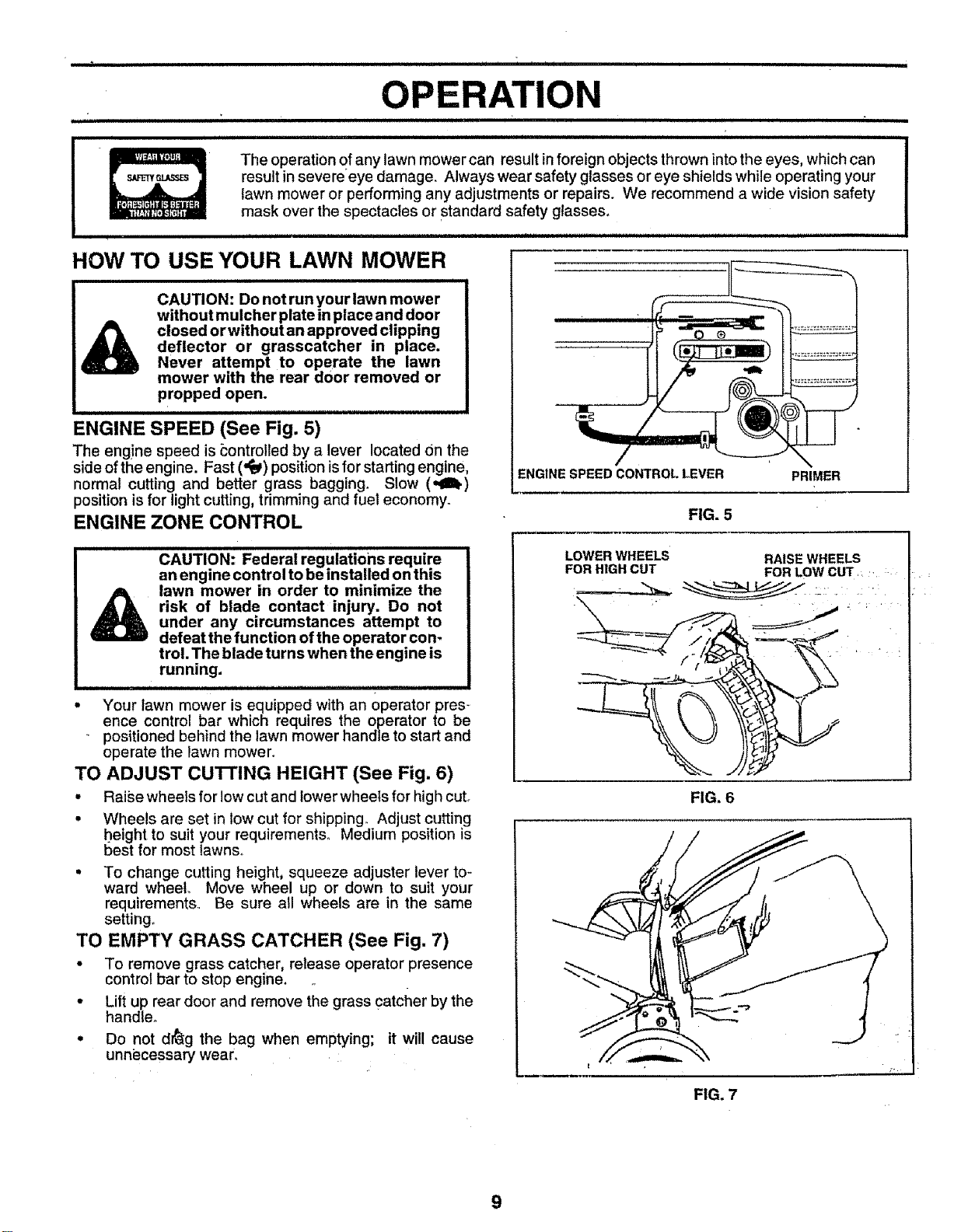
ENGINE SPEED (See Fig. 5)
The eng!ne speed is _ontrolied by a lever located on the
side of the engine. Fast ('_) position isfor starting engine,
normal cutting and better grass bagging. Slow (,,€lh.)
position is for light cutting, trimming and fuel economy.
ENGINE ZONE CONTROL
ENGINESPEEDCONTROLLEVER PRIMER
FIG. 5
CAUTION: Federal regulations require
an engine control to be installed on this
lawn mower in order to minimize the
risk of blade contact injury. Do not
under any circumstances attempt to
defeat the function of the operator con-
trol. The blade turns when the engine is
running.
• Your lawn mower is equipped with an operator pres-
ence control bar which requires the operator to be
positioned behind the lawn mower handle to start and
operate the lawn mower.
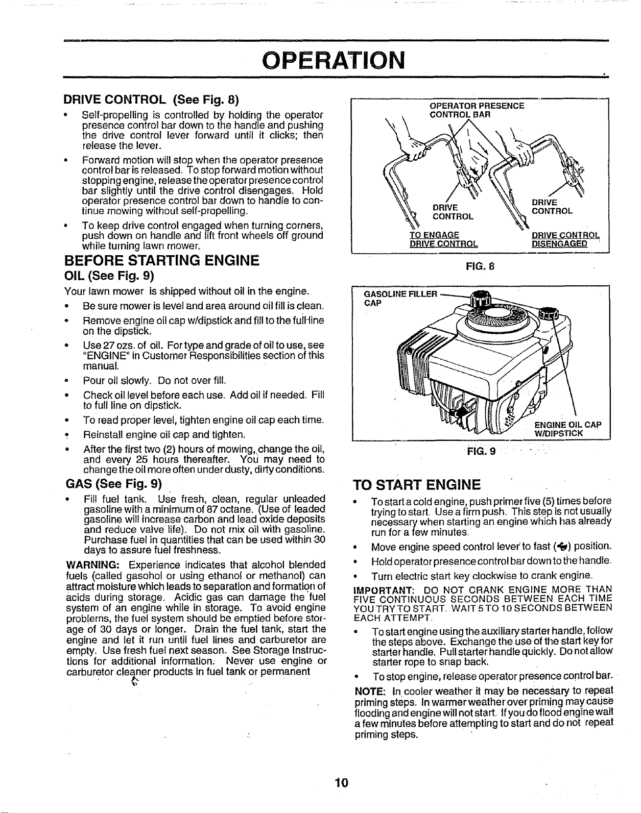
TO ADJUST CUTTING HEIGHT (See Fig. 6)
• Raise wheels for low cut and lower wheels for high cut.
• Wheels are set in low cut for shipping. Adjust cutting
height to suit your requirements° Medium position is
best for most lawns..
• To change cutting height, squeeze adjuster lever to-
ward wheel Move wheel up or down to suit your
requirements. Be sure all wheels are in the same
setting_
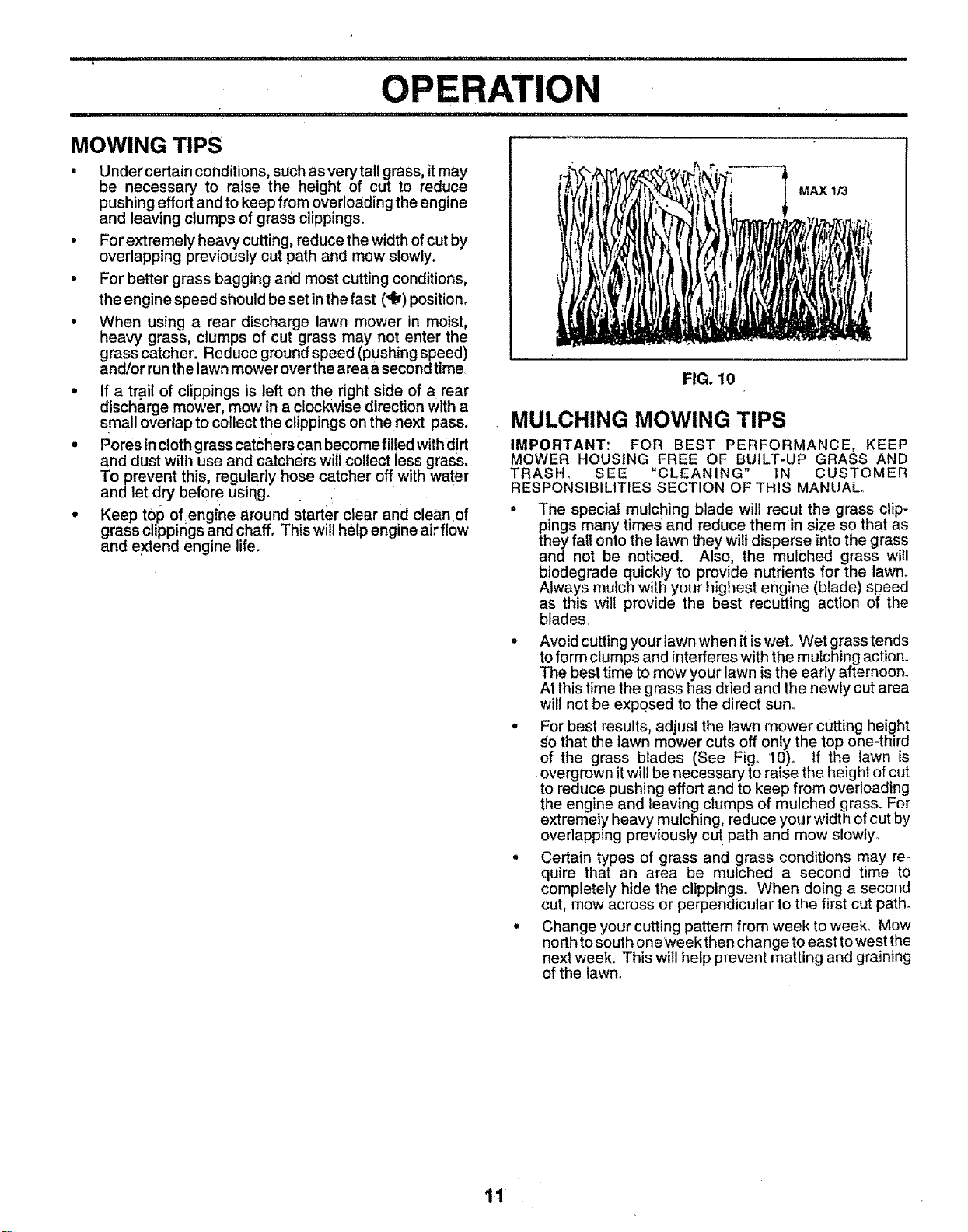
TO EMPTY GRASS CATCHER (See Fig, 7)
• To remove grass catcher, release operator presence
control bar to stop engine.
• Lift up rear door and remove the grass catcher by the
handle_.
o Do not d_g the bag when emptying; it will cause
unni_cessary wear.
LOWERWHEELS RAISEWHEELS
FORHIGHCUT FORLOWCUT, .
k
FIG. 6
FIG. 7
m ......................................................................................... ,, , ,, ,, , ,=r,r=
OPERATION
,HH = =IHH H ,,,,,,,,,,,,,,, ,H H,=HHH= NH",,
DRIVE CONTROL (See Fig, 8)
• Self-propelling is controlled by holding the operator
presence control bar down to the handle and pushing
the drive control lever forward until it clicks; then
release the lever.
= Forward motion wilI stop when the operator presence
control bar is released° To stop forward motion without
stopping engine, release the operator presence control
bar slightly until the drive control disengages. Hold
operator presence control bar down to handte to con-
tinue mowing without self-propelling.
° To keep drive control engaged when turning corners,
push down on handle and lift front wheels off ground
while turning lawn mower:
BEFORE STARTING ENGINE
OIL (See Fig. 9)
Your lawn mower' is shipped without oil in the engine.
° Be sure mower is level and area around oil fill is clean.
• Remove engine oil cap w/dipstick and fill to the fuiHine
on the dipstick.
o Use 27 ozs. of oil. For type and grade of oil to use, see
"ENGINE" in Customer Responsibilities section of this
manual.
• Pour oil slowly_ Do not over fill..
• Check oil level before each use. Add 0il if needed._ Fill
to full line on dipstick.
° To read proper level, tighten engin e oil cap each time..
•. Reinstall engine oil cap and tighten°
° After the first two (2) hours of mowing,change the oil,
and every 25 hours thereafter. You may need to
change the oil more often under dusty, dirty conditions.
GAS (See Fig. 9)
• Fill fuel tank_ Use fresh, dean, regular unleaded
gasoline with a minimum of 87 octane. (Use of leaded
gasoline witl increase carbon and lead oxide deposits
and reduce valve life), Do not mix oil with gasoline.
Purchase fuel in quantities that can be used within 30
days to assure fue! freshness,
WARNING: Experience indicates that alcohol blended
fuels (called gasohol or using ethanol or methanol) can
attract moisture which leads to separation and formation of
acids dudng storage. Acidic gas can damage the fuel
system of an engine while in storag e. To avoid engine
prob!ems, the fuel system should be emptied before stor-
age of 30 days or longer. Drain the fuel tank, start the
engine and let it run until fuel lines and carburetor are
empty. Use fresh fuel next season_ See Storage Instruc-
tions for additional information; Never use engine or
carburetor cleaner products in fuel tank or permanent
OPERATOR PRESENCE
CONTROLBAR
DRIVE
CONTROL
TO ENGAGE
DRIVE CONTRO_
FIG. 8
CAP
DRIVE
CONTROL
DRtVECONTRoL
DISENGAGED
ENGINEOILCAp
W/DIPSTICK
FIG_ 9 .... ::
TO START ENGINE ....
• To start acold engine, push primer five (5) times before
trying to start. Use a firm push.. This step is not usually
necessary when starting an engine which has aIready
run for afew minutes.
° Move engine speed control lever'to fast (,_) position°
° Hold operator presence contro! bar down to t_ehandle_
• Turn electric start key clockwise to crank engine°
IMPORTANT: DO NOT CRANK ENGINE MORE THAN
FIVE CONTINUOUS SECONDS BETWEEN EACH TIME
YOU TRY TO START. WAIT 5 TO 10 SECON DS BETWEEN
EACH ATTEMPT
° To start engine using the auxiliary starter handle, follow
the steps above. Exchange the use of the start key for
starter handle, Put! starterhandle quicklyo Do not allow
starter rope to snap back,
• To stop engine, release ope!ator presence control bar.
NOTE: In cooler'weather' it may be necessary to repeat
priming steps° In warmer weather' over priming may caus_
flooding and engine will not start_ If you do flo0d engine wait
a few minutes before attempting to start and do not repeat
priming steps.
10
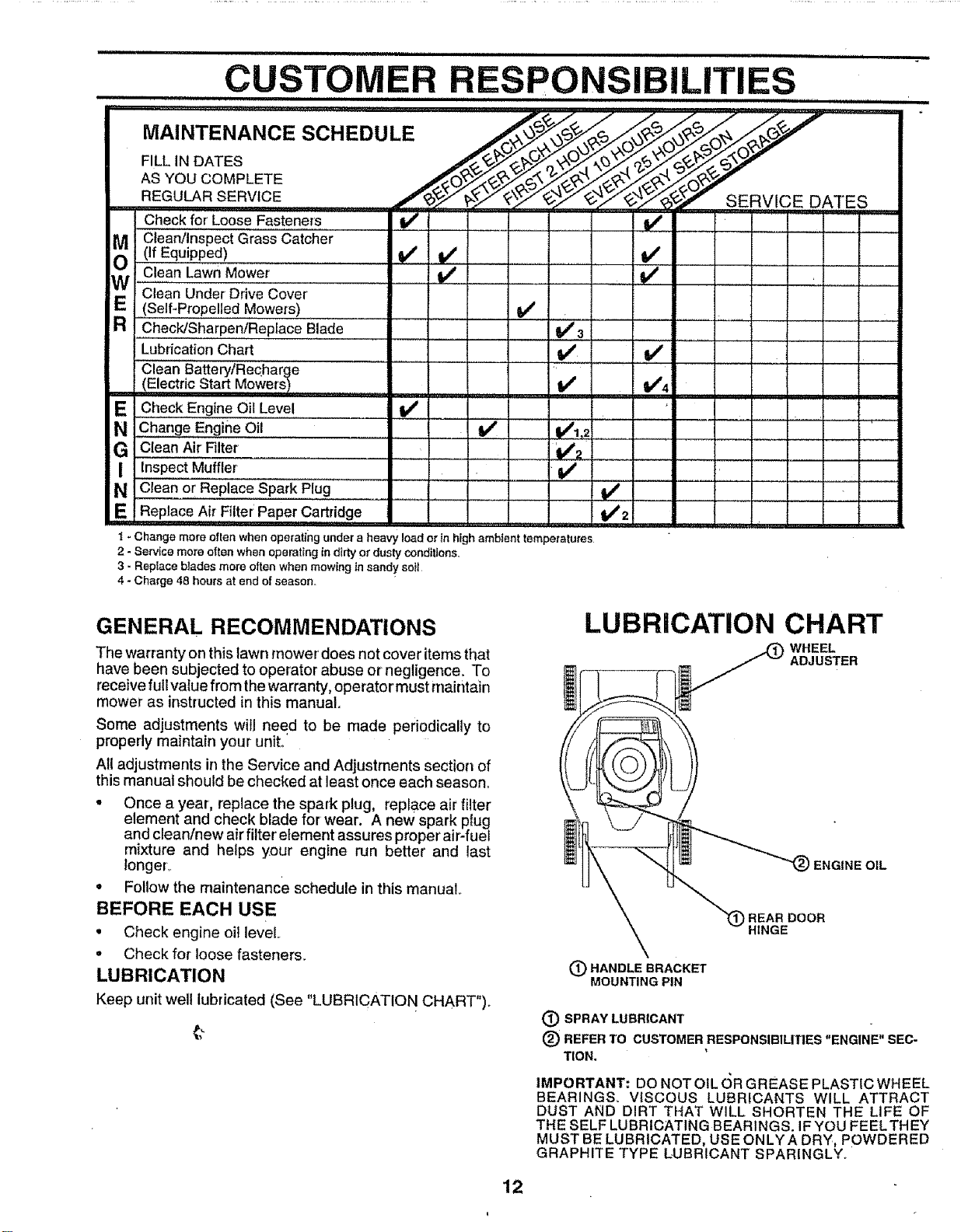
• Under certain conditions, such as very tall grass, itmay
be necessary to raise the height of cut to reduce
pushing effort and to keep from overloading the engine
and leaving clumps of grass clippings,
. For extremely heavy cutting, reduce the width of cut by
overlapping previously cut path and mow slowly,
• For better grass bagging add most cutting conditions,
the engine speed should be set in the fast (dk) position.
• When using a rear discharge lawn mower in moist,
heavy grass, clumps of cut grass may not enter the
grass catcher. Reduce ground speed (pushing speed)
and/or run the lawn mower overthe area a second time°
• If a tr.ai! of clippings is left on the right side of a rear
discharge mower, mow m a clockwise direction wlth a
small overlap to collect the clippings on the next pass.
• Pores in cloth grass catchers can become filled with dirt
and dust with use and catchers will collect less grass.
To prevent this, reguiady hose catcher off with water
and let dry before using°
• Keep top of engine around starter clear and clean of
grass clippings and chaff. This will help engine airflow
and extend engine life.
MAX 1/3
FIG. 10
MULCHING MOWING TIPS
IMPORTANT: FOR BEST PERFORMANCE, KEEP
MOWER HOUStNG FREE OF BUILT-UP GRASS AND
TRASH. SEE "CLEANING" IN CUSTOMER
RESPONSIBILITIES SECTION OF THIS MANUAL.
• The special mulching blade will recut the grass clip-
pings many times and reduce them in size so that as
they fall onto the lawn they wilt disperse into the grass
and not be noticed. Also, the mulched grass will
biodegrade quickly to provide nutrients for the lawn.
Always mulch with your highest engine (blade) speed
as this will provide the best recutting action of the
blades.
• Avoid cutting your lawnwhen it iswet° Wet grass tends
to form clumps and interferes with the mulching action.
The best time to mow your lawn is the early afternoon.
At this time the grass has dried and the newly cut area
will not be exposed to the direct sun.
• For best results, adjust the lawn mower cutting height
go that the lawn mower cuts off only the top one-third
of the grass blades (See Fig. 10),r tf the lawn is
overgrown itwill be necessary to raise the height of cut
to reduce pushing effort and to keep from overloading
the engine and leaving clumps of mulched grass. For
extremely heavy mulching, reduce you r width of cut by
overlapping previously cut path and mow slowly°
• Certain types of grass and grass conditions may re-
quire that an area be mulched a second time to
completely hide the clippings. When doing a second
cut, mow across or perpendicular to the first cut path.
• Change your cutting pattern from week to week_ Mow
north to south oneweek then change to east to west the
next week. This will help prevent matting and graining
of the lawn.
11 L
M Cteanllnspect Grass Catcher
(If Equipped)
Clean Lawn Mower
/ Under Drive Cover
Clean
(Self-Propelled Mowers)
R Check/Sharpen/Replace Blade
Lubrication Chart
Clean Battery/Recharc e
(Electric Start Mowers
E Check Engine Oil Level
N Change Engine Oil
G Clean Air Filter
I Inspect Muffler
N Clean or Replace Spark Plug
E Replace A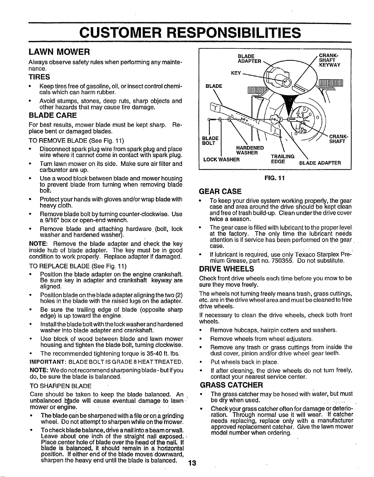
i iii ii i iiii iiiii1,1,1111111,1111111i i rl i
CUSTOMER
= = ................................
LAWN MOWER BU DE ,CRANK-
SHAFT
Always observe safety rules when performing any mainte- ADAPTER_ KEYWAY
nance,.
TIRES KEY
• Keep tires free of gasoline, oil, or insect control chemi- BLADE
cals which can harm rubber.
• Avoid stumps, stones, deep ruts, sharp objects and
other hazards that may cause tire damage.
BLADE CARE
For best results, mower blade must be kept sharp°
place bent or damaged blades_
TO REMOVE BLADE (See Fig_ tl)
Re-
Disconnect spark plug wire from spark piug and place
wire where it cannot come in contact with spark plug.
• Turn lawn mower on its side. Make sure air filter and
carburetor are up.
° Use a wood block between blade and mower housing
to prevent blade from turning when removing blade
bolt;
• Protect your hands with gloves and/or wrap blade with
heavy cloth.
° Remove blade bolt by turning counter-clockwise. Use
a 9/16" box or open-end wrench.
° Remove blade and attaching hardware (bolt, lock
washer and hardened washer),.
NOTE: Remove the blade adapter and check the key
inside hub of blade adapter. The key must be in good
condition to work properly., Replace adapter if damaged.
TO REPLACE BLADE (See Fig: 11)
• Position the blade adapter on the engine crankshaft.
Be sure key in adapter and crankshaft keyway are
aligned,.
• Position blade on the blade adapter aligningthe two (2)
ho}es in the blade with the raised lugs on the adapter.
• Be sure the trailing edge of blade (opposite sharp
edge) is up toward the engine°
• Install the blade bolt with the lock washer and harde ned
washer into blade adapter and crankshaft.
• Use block of wood between blade and lawn mower
housing and tighten the blade bolt, turning clockwise.
• The recommended tightening torque is 35-40 fL Ibs.
IMPORTANT: BLADE BOLT IS GRADE 8 HEATTREATED.
NOTE: We do not recommend sharpening blade- but ifyou
do, be sure the blade is balanced,.
TO SHARPEN BLADE
Care should be taken to keep the blade balanced. An ,
unbalanced b_de will cause eventual damage to lawn-
mower or englne_ ..: .....
• The blade can be sharpened with a file Or ona grinding
wheel, Do not attempt to sharpen while on the Rower°
° To check blade balance, dr_vea nail into a beam orwalL
Leave about one inch of the straight nail exposed:,
Place.center hole of blade over the head of the nail: If
blade is balanced, it should remain in a horizontal
position. If either end of the blade moves downward,
sharpen the heavy end until the blade is balanced.
13
•CRANK-
SHAFT
TRAILING
EDGE BLADE ADAPTER
FIG. 11
GEAR CASE
• To keepyour drive system working properly, the gear
case andarea around the drive should be kept clean
and free oftrash build-up. Clean under the dPivecover
twice a season.
° The gear case isfilled with lubricant to the proper leye!
at the factory. The only time the lubricant needs
attention isif service has been performed on the gear
case. . .
• If lubricant is required, use 0nly Te:<aco Starplex Pre J
mium Grease, part non750355,. Do not substitute.
DRIVE WHEELS
Check front drive wheels each time before you mow to be
sure they move freely.
The wheels not turning freely means trash, grass cuttings,
etc. are in the drive wheel area and must be cleaned to free
drive wheels.
If necessary to clean the drive wheels, check both front
wheels.
• Remove hubcaps, hairpin cotters and washers.
° Remove wheets from wheet adjusters.
• Remove any trash or grass cuttings from inside the
dust cover, pinion and/or drive wheel gear teeth.
• Put wheels back in place..
• If after cleaning, the drive wheels do not turn freely,
contact your nearest service center,.
GRASS CATCHER
• The grass catcher may be hosed with water, but must
be dry when used. . _ . .: .
° Check your grass catcher often for damage or deterio-
i ration. Through normal use it will wear. If catcher
needs replacing, replace only with a manufacturer
approved replacement catcher. Give the lawn mower
model number when ordering,
_L ................. : = ,= =IHHIH=' ,HHH,H H ===H=H
ENGINE
LUBRICATION
Use only high quality detergent oil rated with API service
classification SF orSG. Select the oil's SAE viscositygrade
according to your expected operating temperature.
SAE VISCOSITY GRADES
"F -20" 0= 30" 32 ° 40" 60" 80 _...... 100"
°c .3o" -2_- ._o. G' _" 20' • 30- 40"
TE_PE_'roRERANaEA_noJP^TEOBEFORENEXTO_LCHANGE
NOTE: Although multi-viscosity oils (5W30, 10W30 etc.)
improve starting in cold weather, these multi;viscositY oils
will result in increased oil consumption when used above
32°F. Check your engine oil level more frequently to avoid
possible engine damage from running low on oil.
Change the oil after the first two hours of operation and
every 25 hours thereafter or at least once ayear' ifthe lawn
mower is not used for'25 hours in one year.
Check the crankcase oil level before starting the engine
and after each five (5) hours of continuous use° Tighten oil
plug securely each time you check the oil level°
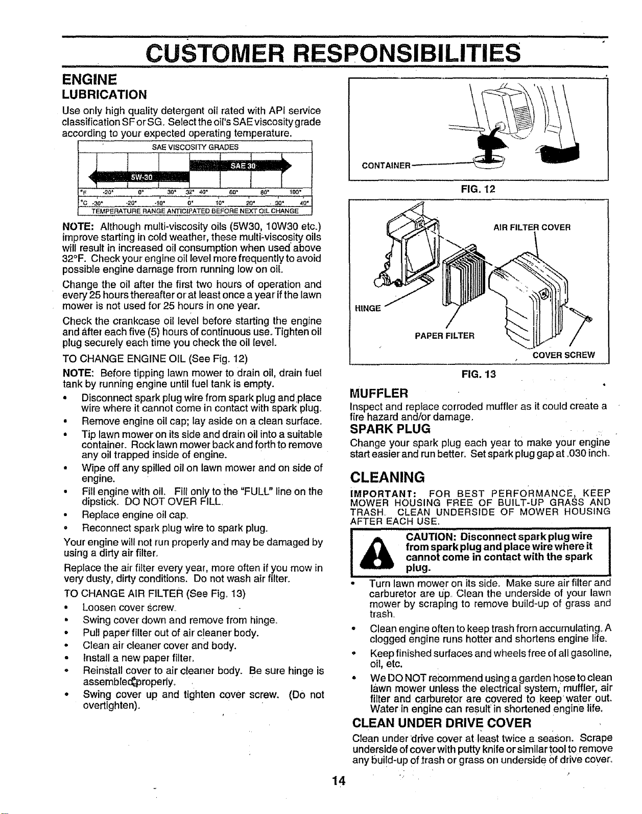
TO CHANGE ENGINE OIL (See Fig. 12)
NOTE: Before tipping lawn mower tO drain oil, drain fuel
tank by running engine until fuel tank is empty.
• Disconnect spark plug wire from spark plug and,place
wire where it cannot come in contact with spark plug.
• Remove engine oil cap; lay aside on a clean surface.
• Tip lawn mower on its side and drain oil into a suitable
container° Rock lawn mower back and forth to remove
any oil trapped inside of engine.
• Wipe off any spilled oit on lawn mower and on side of
engine.
• Fill engine with oil. Flit only to ;_he"FULL" line on the
dipstick. DO NOT OVER FILL,
• Replace engine oil cap.,
o Reconnect spark plug wire to spark plug.
Your engine will not run properly and may be damaged by
using a dirty air filter.
Replace the air' filter every year, more often if you mow in
very dusty, dirty conditions. Do not wash air filter.
TO CHANGE AIR FILTER (See Fig° 13)
. Loosen cover Screw_
• Swing cover down and remove from hinge.
• Putl paper filter out of air c!eaner body.
• Clean air cleaner cover and body,
. Install a new paper filter.
° Reinstall cover to air cleaner body. Be sure hinge is
assembfec_properlyo ,
• Swing cover up and tighten cover screw. (DO not
overtighten).
CONTAINER'
FIG, 12
AIR FILTER COVER
HINGE/
/
PAPER FILTER
14
COVERSCREW
CLEANING
IMPORTANT: FOR BEST PERFORMANCE, KEEP
MOWER HOUSING FREE OF BUILT-UP GRASS AND
TRASH CLEAN UNDERSIDE OF MOWER HOUSING
AFTER EACH USE,
HH=I=IHH= I = = 'JI
CAUTION: Disconnect spark plug wire
from spark plug and place wire where it
cannot come in contact with the spark
plug.
• Turn lawn mower on its si'd'e_ Make Sure air filter and
carburetor are up,, Clean the underside of your lawn
mower by scraping to remove build-up of grass and
trash_
° Clean engine often to keep trash from accumulating° A
clogged engine runs hotter' and shortens engine lifeo
o Keep finished surfaces and wheels free of all gasoline,
oil, etc.
° We DO NOT recommend us ng a garden hose to clean
le,wn mower unless the electrical system,,' muffler, air
filter and carburetor are covered to keep' water out,
Water in engine can resultin shortened engine life_
CLEAN UNDER DRIVE COVER
Clean underdrive cover at least twice a season. Serape
underside of cover with putty knife orsimilar tool tOremove
any bui!d-up of trash or grass on underside Ofdrive cover.
FIG. 13
MUFFLER
Inspect and replace corroded muffler' as itcould create a
fire hazard and/or damage.
SPARK PLUG
Change your spark plug each year to make your' engine
start easier and run better'° Set sp=irk plug gap at .030 inch,,
CAUTION: BEFORE PERFORMING ANY SERVICE OR ADJUSTMENTS:
Release control bar.
* Make sure the blade and all moving parts have completely stopped.
* Disconnect spark plug wire from spark plug and place where it cannot come in contact with plug.
LAWN MOWER
TO ADJUST CUTTING HEIGHT
See "TO ADJUST CUTTING HEIGHT _'in the Operation
section of this manual.
REAR DEFLECTOR
The rear deflector, attached between the rear wheels of
your lawn mower, is provided to minimize the possibility
that objects will be thrown out the rear of the lawn mower
into theoperator's mowing position, !f the rear deflector
becomes damaged, it should-be replaced.
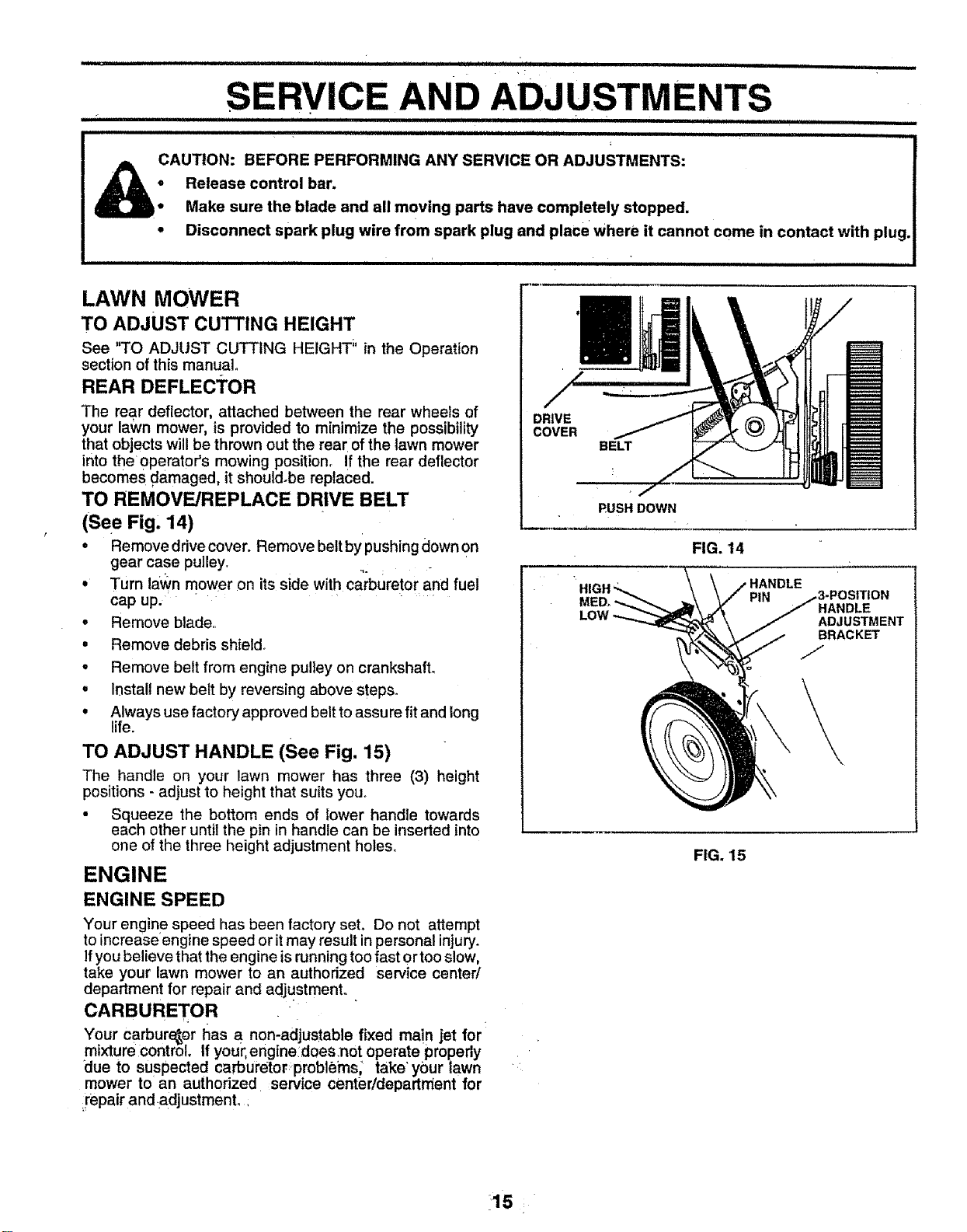
TO REMOVE/REPLACE DRIVE BELT
(See Fig. 14)
• Remove drive cover. Remove belt bypushing downOn
gear case pulley.
° Turn la'wn mower on its side with carburetor and fuel
cap up.
. Remove blade.
. Remove debris shield.
o Remove belt from engine pulley on crankshaft.
. Install new belt by reversing above steps.
° Always use factory approved belt to assure fit and long
life.
TO ADJUST HANDLE (See Fig, 15)
The handle on your lawn mower has three (3) height
positions - adjust to height that suits you.
• Squeeze the bottom ends of lower handle towards
each other until the pin in handle can be inserted into
one of the three height adjustment holes.
ENGINE
ENGINE SPEED
Your engin e speed has been factory set. Do not attempt
to increase engine speed or it may result in personal injury.
If you believe that the engine is running too fast or too slow,
take your lawn mower to an authorized service center/
department for repair and adjustment..
CARBURETOR
Your carburetor has a non-adjustable fixed main jet for
mixture control If your, engine does.not operate propedy
"due to susPected carburetor;problems; take' your lawn
mower to an authorized service center/department for
impair and adjustment.,
DRIVE
COVER
BELT
PUSH DOWN
FIG. 14
HIGI
LOW
HANDLE
ADJUSTMENT
BRACKET
FIG. 15
!s,
........................._..... nl" '"' ii .......................... nnnll u .................. lunnnll i n
STORAGE
. illllU.... n l iI i i i illllnnnnl
Immediately prepare your lawn mower for storage at the
end of the season or if the unit will net be used for 30 days
or' more.
LAWN MOWER
When lawn mower isto be stored fora periodof time, clean
it thoroughly, remove all dirt, grease, leaves, etc, Store in
a clean, dry are&
• Clean entire lawn mower (See "CLEANING" in the
Customer Responsibilities section of this manual).
• Lubricate as shown in the Customer Responsibilities
section of this manual.
, Be sure that all nuts, bolts, screws, and pins are
securely fastened° Inspect moving parts for'damage,
breakage and wear.. Replace if necessary.
° Touch up atl rusted or' chipped paint surfaces; sand
lightly before painting_
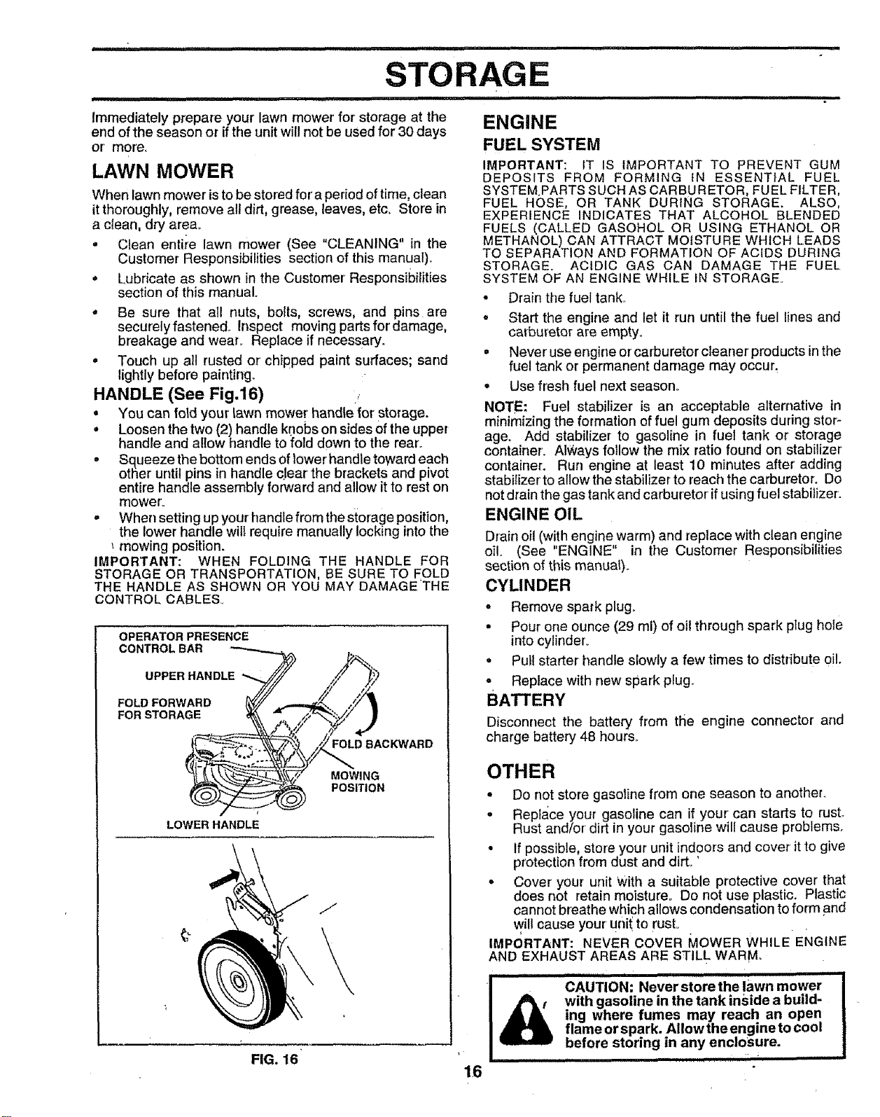
HANDLE (See Fig,16)
• You can fold your lawn mower handle tot' storage.
° Loosen the two (2) handle knobs on sides of the upper
handle and allow handle to fold down to the rear.
, Squeeze the bottom ends of lower handle toward each
other unti pins in hand e cJear the brackets and pivot
entire handle assembly forward and allow it to rest on
mower.
- When setting up your handle from the storage position,
the lower handle will require manually locking into the
mowing position.
IMPORTANT: WHEN FOLDING THE HANDLE FOR
STORAGE OR TRANSPORTATION, BE SURE TO FOLD
THE HANDLE AS SHOWN OR YOU MAY DAMAGETHE
CONTROL CABLES_
OPERATOR PRESENCE
CONTROL BAR
UPPER HANDLE J
FOLD FORWARD
FOR STORAGE _ ,zx& _,,,..
LOWER HANDLE
,,Ft
D 8_ AC_ARD
MOWING
)_ POSITION
J
FIG. 16
ENGINE
FUEL SYSTEM
IMPORTANT: IT IS iMPORTANT TO PREVENT GUM
DEPOSITS FROM FORMING tN ESSENTIAL FUEL
SYSTEM,PARTS SUCH AS CARBURETOR, FUEL FILTER,
FUEL HOSE, OR TANK DURING STORAGE. ALSO,
EXPERIENCE INDICATES THAT ALCOHOL BLENDED
FUELS (CALLED GASOHOL OR USING ETHANOL OR
METHANOL) CAN ATTRACT MOISTURE WHICH LEADS
TO SEPARATION AND FORMATION OF ACIDS DURING
STORAGE. ACIDIC GAS CAN DAMAGE THE FUEL
SYSTEM OF AN ENGINE WHILE iN STORAGE.
° Drain the fuel tank.
o Start the engine and let it run until the fuel lines and
caTburetor are empty=
= Never' use engine or carburetor cleaner products in the
fuel tank or permanent damage may occur_
° Use flesh fuel next season..
NOTE: Fuel stabilizer is an acceptable alternative in
minimizing the formation of fuel gum deposits during stor-
age_ Add stabilizer to gasoline in fuel tank or storage
container. Always follow the mix ratio found on stabilizer
container. Run engine at least 10 minutes after adding
stabilizer'to allow the stabilizer to reach the carburetor. Do
not drain the gas tank and carburetor if using fuel stabilizer.
ENGINE OIL
Drain oil (with engine warm) and replace with clean engine
oil= (See "ENGINE" in the Customer Responsibilities
section of this manual).
CYLINDER
• Remove spark plugo
• Pour one ounce (29 ml) of oi! through spark plug hole
into cylinder.
• Pull starter handle slowly a few times to distribute oil.
° Replace with new spark plug_
BATTERY
Disconnect the battery from the engine connector and
charge battery 48 hour&
OTHER
• Do not store gasoline from one season to another.
° Replace your gasoline can if your' can starts to rust.
Rust and/or dirt in your gasoline will cause problems.
• If possible, store your unit indoors and cover it to give
protection from dust and dirL '
o Cover your unit With a suitable protective cover that
does not retain moisture_ Do not use plastic. Plastic
cannot breathe which allows condensation to form and
will cause your unit to rusL
IMPORTANT: NEVER COVER MOWER WHILE ENGINE
AND EXHAUST AREAS ARE STILL WARM_
IIIIIIIIIIIIA........!
" CAUTION: Neverstore the lawn mower
with gasoline in the tank inside a build-
ing where fumes may reach an open
flame or spark. Allow the engine to cool
before storing in any enclosure.
nnlllllllnl ii I II II IIIIII
16
.......... "..... iiiiiiiiiiiiiiiii i i i i iiiii i
TROUBLESHOOTING POINTS
_uii i i i iiiimllllll iiiiiiiiii iii iiiiiiiiiiiiiii i i
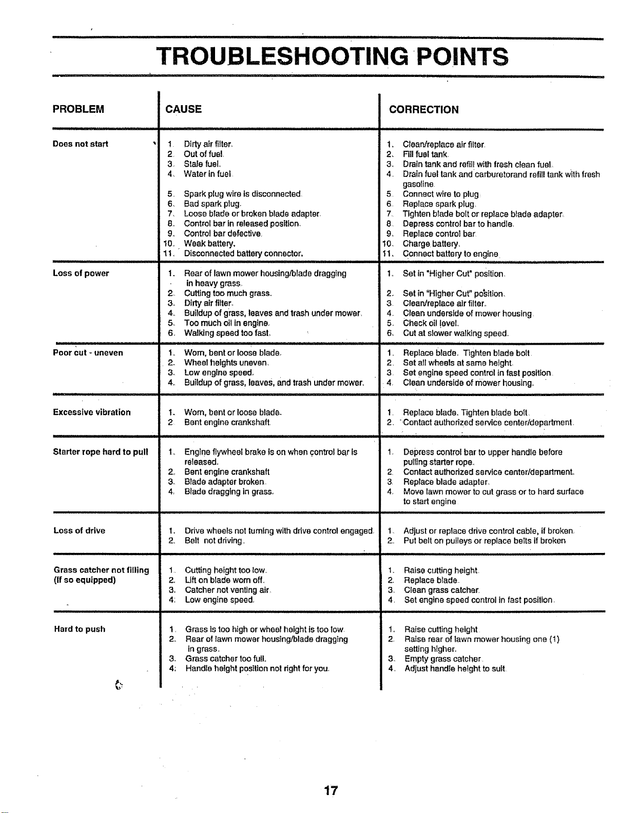
PROBLEM
Does not start
Loss of power
ii ii ii ii i i
Poor cut - uneven
i
Excessive vibration
Starter rope hard to pull
i i
Loss of drive
Grass catcher not filling
(If so equipped)
Hard to push
CAUSE
1 Dirty a_r filter.
2 Out of fue!
3 Stale fuel
4 Water In fuel
5 Spark plug wire is disconnected
6. Bad spark plug.
7. Loose blade or broken blade adapter,
8. Control bar in released position_
9. Control bar defective
t0,. Weak battery.
11. Disconnected battery connector,
t. Rear of lawn mower housing/blade dragging
in heavy grass,
2o Cuffing too much grass°
3. Dirty air filter.
4. Butfdup of gt'ass, leaves and trash under mower.
5. Too much oil in engine.
6, Walking speed too fast.
i iii i i i i i i i
1. Worn, bent or loose blade.
2. Wheel heights uneven.
3. Low engine speed°
4o Butldup of grass, leaves, and trash under mower,,
1. Worn, bent or loose blade_
2 Bent engine crankshaft.
1. Engtne flywheel brake is on when control bar Is
released.
2,, Bent engine crankshaft
3° Blade adapter broken
4. Blade dragging in grass°
1. Drive wheels not turning with drive control engaged,
2, Belt not driving,
1. Cutting height too low.,
2, Lift on blade worn off,
3. Catcher not venting air,
4; Low engine speed.
t, Grass is too high or wheel height |s too Iow
2. Rear of lawn mower housing/blade dragging
in grass,
3. Grass catcher too full.,
4: Handle height posffion not right for you,
CORRECTION
1_ Clean/replace air filter
2. Fill fuel tank.
3, Drain tank and refill with fresh clean fuel,
4 Drain fuel tank and'carburetorand refill tank With fresh
gasoline
5 Connect wire to plug
6 Replace spark plug,
7 Tighten blade bolt or replace blade adapter,
8 Depress control bet to handle,
9. Replace control bar
I0. Charge battery.
11. Connect battery to engine
1. Set in =Higher Cut" position,
2., Set in "Higher Cut" po'sitton.
3 Clean/replace air filter,.
4, Clean underside of mower housing
5. Check oil !eveL
6. Cut at slower walking speed°
iiiiiiiiiiiiiiiiiiiiiiiiiiiiiiiiiii i
1, Replace blade. Tighten blade bolt
2. Set all wheels at same heighL
3 Set engine speed control in fast position
4, Clean underside of mower housing,
, i
1 Replace blade. Tighten blade bolt,
2, Contact authorized service centeddepartment,
,,,,,, ,,,,,,,,,,,, ,,, ,, ,,,,,,,,,,,,,,,,,,,
1. Depress control bar to upper handle before
pulting starter rope.r
2 Contact aulhorized service centeddepadment°
3 Replace blade adapter.
4. Move lawn mower to cut grass or to hard surface
to start engine
1. Adjust or replace drive control cable, if broken.
2., Put belt on pufleys or replace belts if broken
1. Raise cutting height
2 Replace blade
3 Clean grass catcher.
4, Set engine speed control in fast position
i
1_ Raise cutting height
2. Raise rear of lawn mower housing one (1)
setting higher.
3, Empty grass catcher,
4, Adjust handle height to suit
17
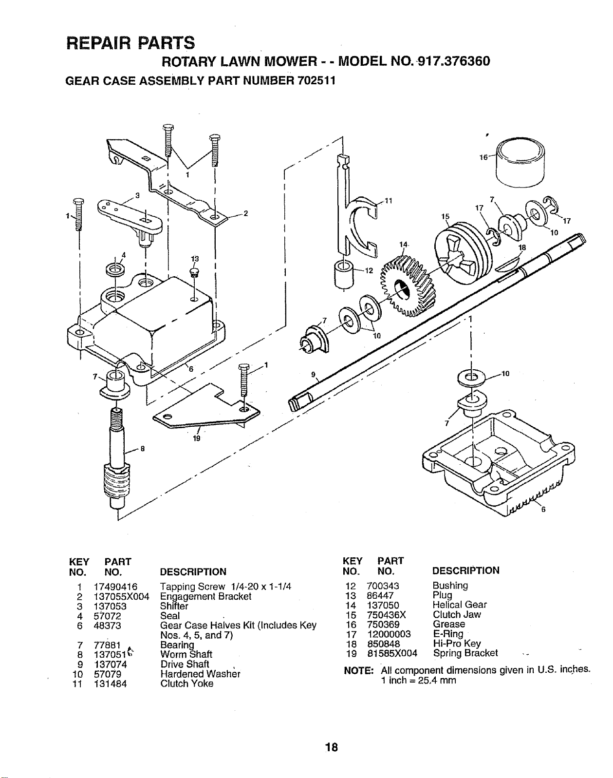
REPAIR PARTS
ROTARY LAWN MOWER -- MODEL NO.917.376360
GEAR CASE ASSEMBLY PART NUMBER 702511
tg
J
J
J
J
j+
10
14
15
17
18
10
• ,10
7
KEY PART
NO. NO.
1 1749O416
2 137055X004
3 137053
4 57072
6 48373
7 77881
8 137051_
9 137074
10 57079
11 131484
DESCRIPTION
Tapping Screw 1/4_20 x 1-1/4
Engagement Bracket
Shifter
Seat
Gear Case Haives Kit (Includes Key
Nos+4, 5, and 7)
Bearing
Worm Shaft
Drive Shaft
Hardened Washer
Clutch Yoke
KEY PART
NO. NO.
DESCRIPTION
12 700343 Bushing
13 86447 Plug
14 137050 Helical Gear
15 750436X Clutch Jaw
16 750369 Grease
17 12000003 E-Ring
18 850848 Hi-Pro Key
19 81585X004 Spring Bracket
NOTE: All component dimensions given in U.S. inc+hes,
1 inch = 25+4mm
18
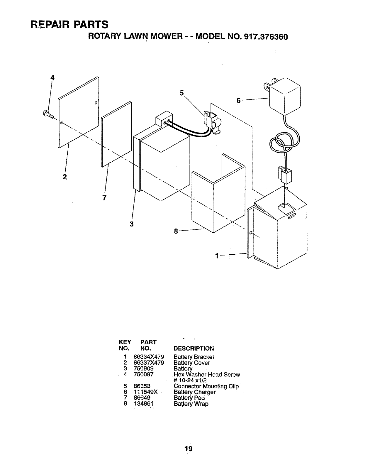
REPAIR PARTS
ROTARY LAWN MOWER - - MODEL NO. 917.376360
4
2
7
3
8
KEY PART
NO. NO. DESCRIPTION
1 86334X4'79 Battery Bracket
2 86337X479 Battery Cover
3 750909
4 750097
5 86353
6 11t549X i
7 86649
8 13,4861
Battery
Hex Washer Head Screw
# 10-24 xl/2
Connector Mounting Clip
Battery Charger
Battery Pad
Battery Wrap
19
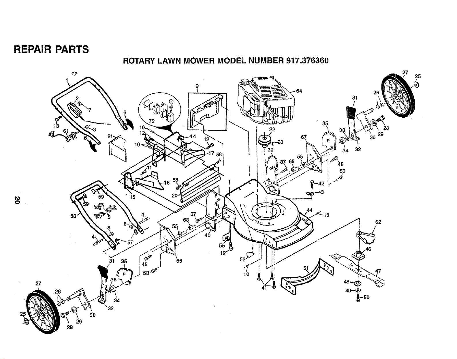
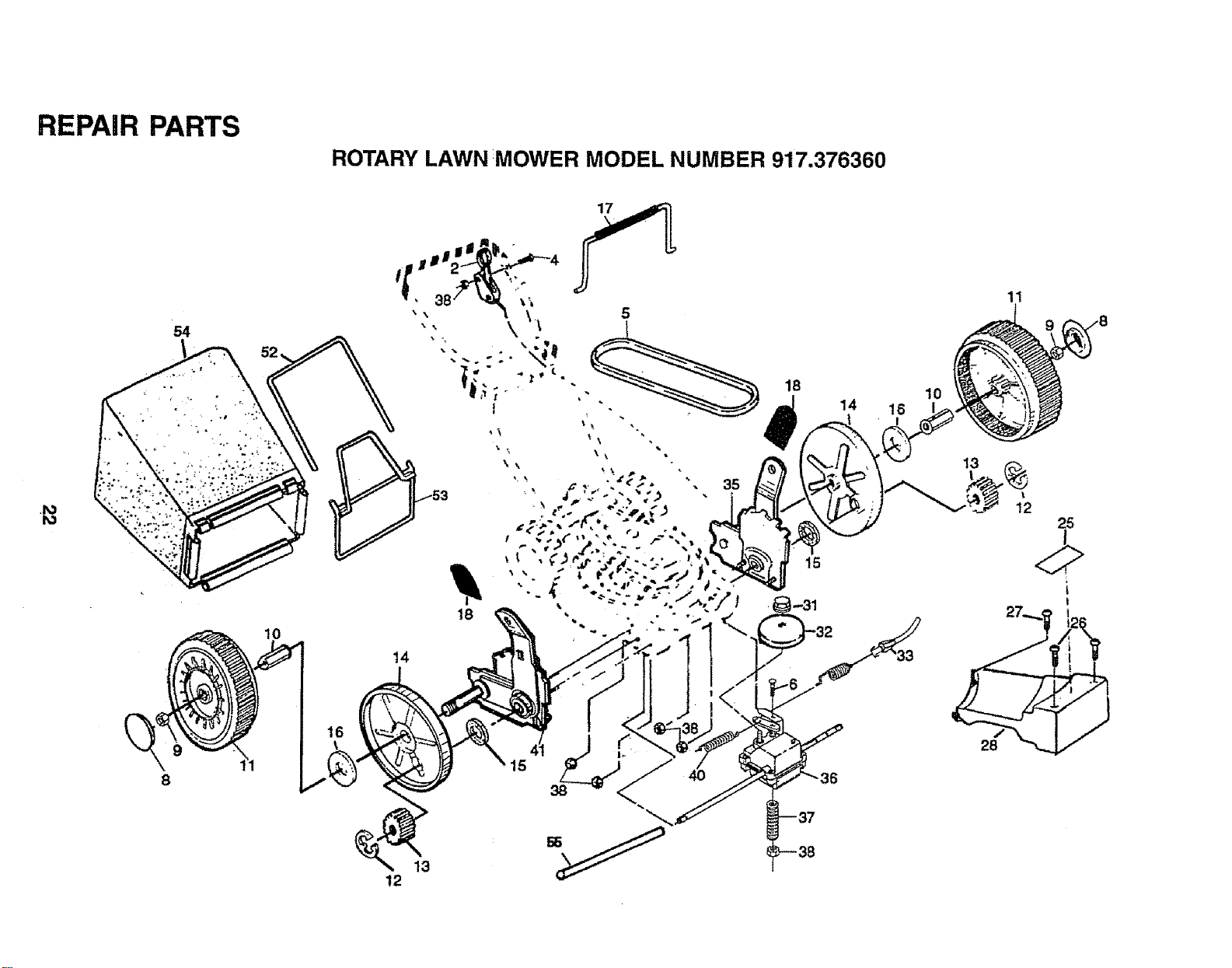
REPAIR PARTS
ROTARY LAWN MOWER MODEL NUMBER 917.376360
o
72
9
67
55
35
31
32
26
28
29
30
25
26
31
34
35
4
37
68
55
10
62
REPAIR PARTS
ROTARY LAWN MOWER MODEL NUMBER 917.376360
to
_J.
KEY PART
NO. NO
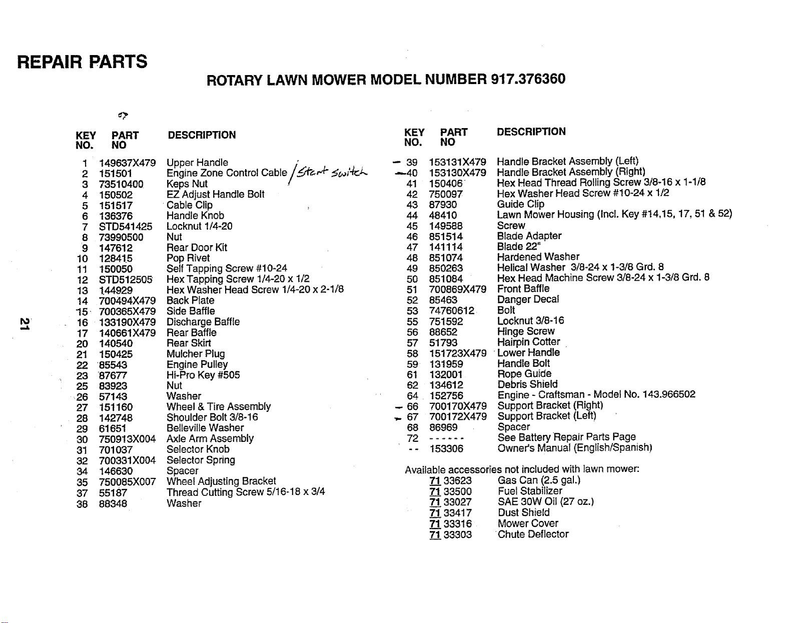
1 149637)(479
2 151501
3 73510400
4 150502
5 151517
6 136376
7 STD541425
8 73990500
9 147612
10 128415
11 150050
12 STD512505
13 144929
14 700494X479
15 _ 700365)(479
16 133190X479
17 140661X479
20 140540
21 150425
22 85543
23 87677
25 83923
26 57143
27 151160
28 142748
29 61651
30 750913X004
31 701037
32 700331X004
34 146630
35 750085X007
37 55187
38 88348
DESCRIPTION
Upper Handle _ .,
Engine Zone Control Cable/.jf_, _ _,qr.J.-
Keps Nut
EZ Adjust Handle Bolt
Cable Clip
Handle Knob
Locknut 1/4-20
Nut
Rear Door Kit
Pop Rivet
Self Tapping Screw #10-24
Hex Tapping Screw 1/4-20 x 1/2
Hex Washer Head Screw 1/4-20 x 2-1/8
Back Plate
Side Baffle
Discharge Baffle
Rear Baffle
Rear Skirt
Mulcher Plug
Engine Pulley
Hi-Pro Key #505
Nut
Washer
Wheel & Tire Assembly
Shoulder Bolt 3/8-16
Belleville Washer
Axle Arm Assembly
Selector Knob
Selector Spring
Spacer
Wheel Adjusting Bracket
Thread Cutting Screw 5/16-18 x 3/4
Washer
KEY PART DESCRIPTION
NO. NO
-'- 39 153131X479
-,--40 153130X479
41 150406
42 75009T
43 87930
44 48410
45 149588
46 851514
47 141114
48 851074
49 850263
50 851084
51 700869X479
52 85463
53 74760612
55 751592
56 88652
57 51793
58 151723X479
59 131959
61 132001
62 134612
64 152756
-- 66 700170)(479
67 700172X479
68 86969
-- 153306
Handle Bracket Assembly (Left)
Handle Bracket Assembly (Right)
Hex Head Thread Rolling Screw 3/8-16 x 1-1/8
Hex Washer Head Screw #10-24 x 1/2
Guide Clip
Lawn Mower Housing (Incl. Key #t4,15, 17, 51 & 52)
Screw
Blade Adapter
Blade 22"
Hardened Washer
Helical Washer 3/8-24 x 1-3/8 Grd. 8
Hex Head Machine Screw 3/8-24 x 1-3/8 Grd. 8
Front Baffle
Danger Decal
Bolt
Locknut 3/8-16
Hinge Screw
Hairpin Cotter
Lower Handle
Handle Bolt
Rope Guide
Debris Shield
Engine - Craftsman - Model No. 143.966502
Support Bracket (Right)
Support Bracket (Left)
Spacer
See Battery Repair Parts Page
Owner's Manual (English/Spanish)
Available accessories not included with lawn mower:
7"133623
7"133500
7"133027
7_/133417
7.133316
7.133303
Gas Can (2.5 gal.)
Fuel Stabilizer
SAE 30W Oil (27 oz.)
Dust Shield
Mower Cover
Chute Deflector
REPAIR PARTS
ROTARY LAWN MOWER MODEL NUMBER 917.376360
.M
54
10
14
13
12
14 16
10
1!
13
12
25
I
i
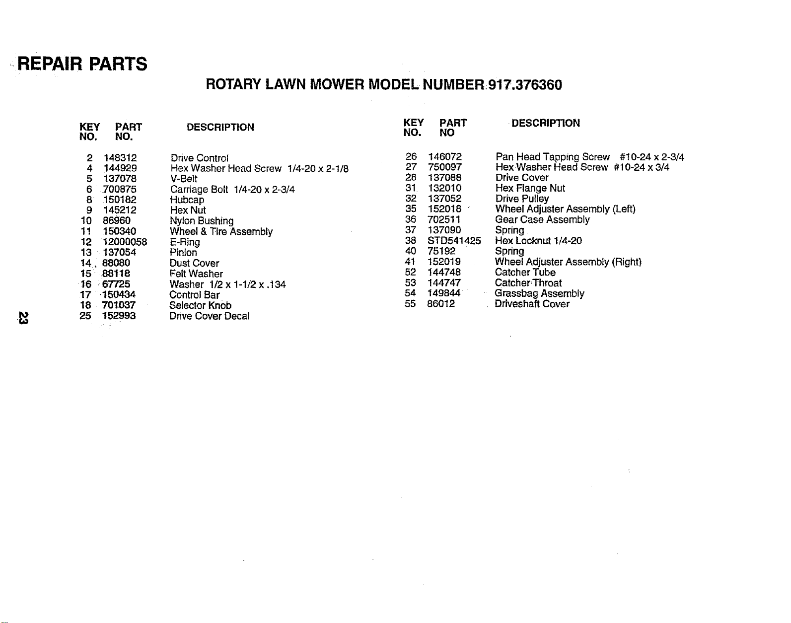
REPAIR PARTS
ROTARY LAWN MOWER MODEL NUMBER917,376360
to
,€,,_
KEY PART
NO. NO.
2 148312
4 144929
5 137078
6 700875
8 ,150182
9 145212
10 86960
11 150340
12 12000058
13 137054
14, 88080
15 ,88118
16 167725
17 -150434
18 701037
25 152993
KEY PART DESCRIPTION
DESCRIPTION NO. NO
Drive Control 26 146072
Hex Washer Head Screw 1/4-20 x 2-t/8 27 750097
V-Belt 28 137088
Carriage Bolt !/4-20 x 2-3/4 31 132010
Hubcap 32 137052
Hex Nut 35 152018
Nylon Bushing 36 702511
Wheel & Tire Assembly 37 137090
E-Ring 38 STD541425
Pinion 40 75192
Dust Cover 41 152019
Felt Washer 52 144748
Washer 1/2 x !-!/2 x .i34 53 144747
Control Bar 54 149844
Setector Knob 55 86012
Drive Cover Decal
Pan Head Tapping Screw #10-24 x 2-3/4
Hex Washer Head Screw #10-24 x 3/4
Drive Cover
Hex Flange Nut
Drive Pulley
Wheel Adjuster Assembly (Left)
Gear Case Assembly
Spring
Hex Locknut 1/4-20
Spring
Wheel Adjuster Assembly (Right)
Catcher Tube
Catcher,Throat
Grassbag Assembly
Ddveshaft Cover
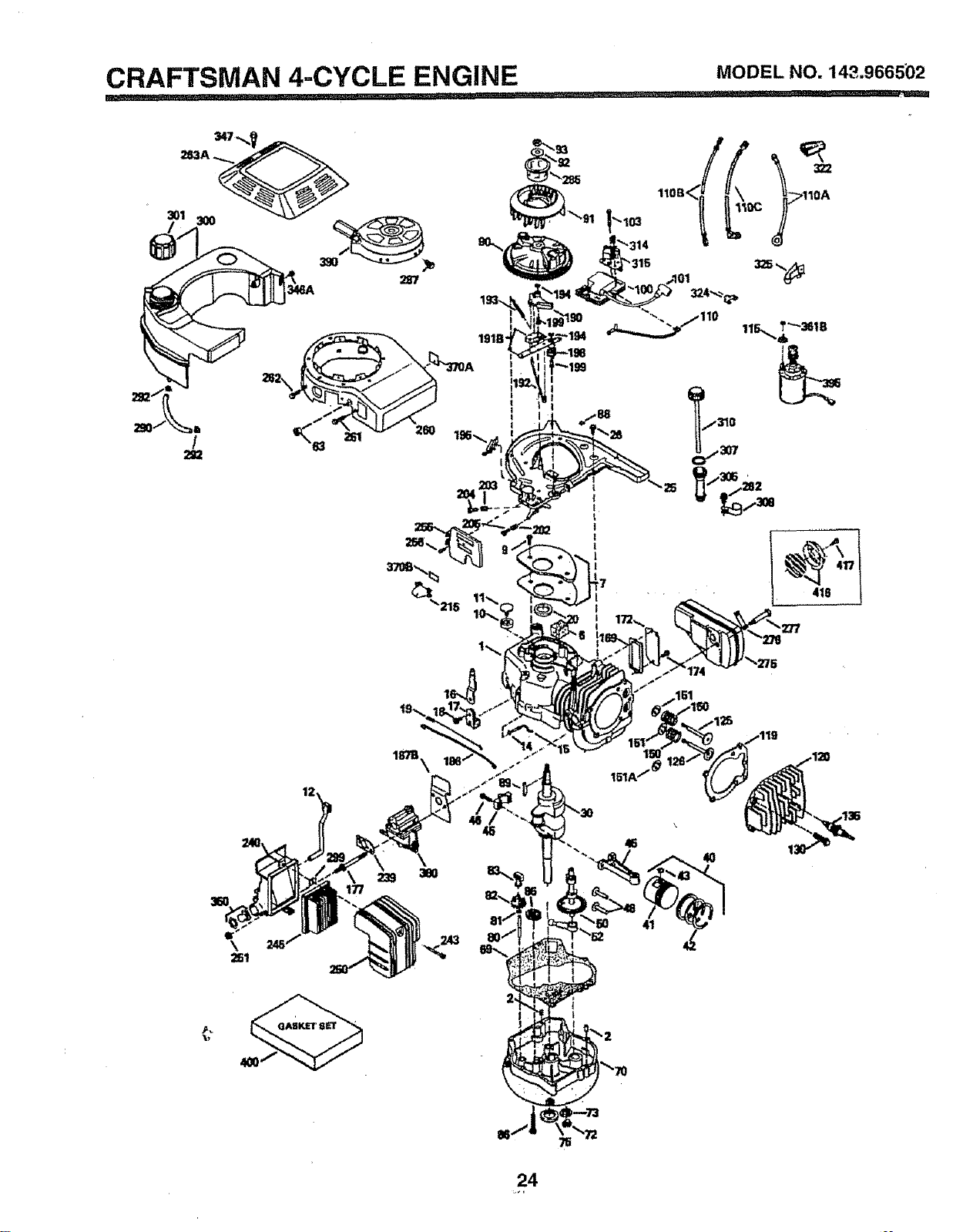
CRAFTSMAN 4-CYCLE ENGINE
MODEL NO. 143.966502
=, il IL. _uu,',,,'H
12
.119
46
41
4O
24
CRAFTSMAN 4-CYCLE ENGINE MODELNO.143.966502
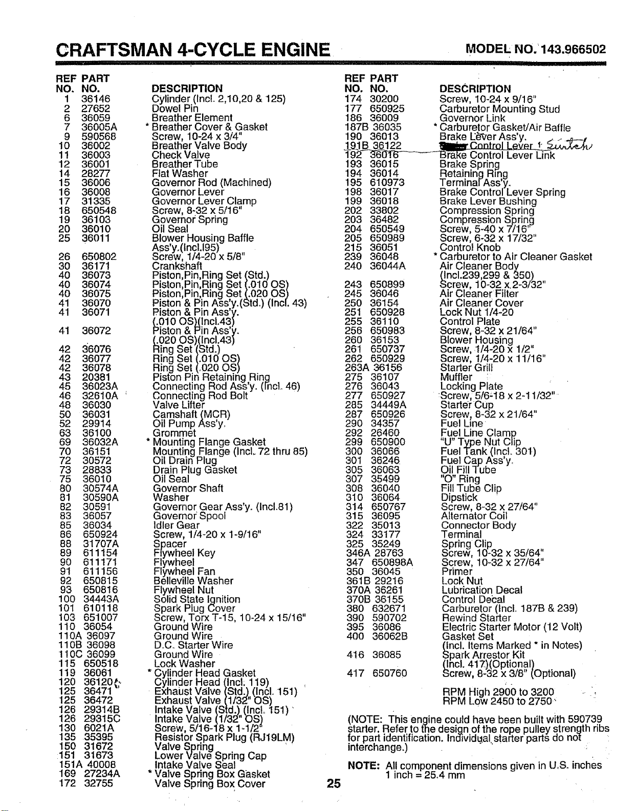
, II I I IIII III IIII IIIII
REF PART
NO. NO.
1 36146
2 27652
6 36059
7 36005A
9 590568
10 36002
11 36003
12 36001
14 28277
15 36006
16 36008
17 31335
18 650548
19 36103
20 36010
25 36011
26 65O8O2
30 36171
40 36073
40 36074
40 36075
41 36070
41 36071
41 36072
42 36076
42 36077
42 36078
43 20381
45 36023A
46 32610A !
48 36030
50 36031
52 29914
63 36100
69 36032A
70 36151
72 30572
73 28833
75 36010
80 30574A
81 30590A
82 30591
83 36057
85 36034
86 650924
88 31707A
89 611154
90 611171
91 611156
92 650815
93 650816
100 34443A
101 610118
103 651007
110 36054
110A 36097
110B 36098
110C36099
115 650518
119 36061
120 36120_
125 36471
125 36472
126 29314B
126 29315C
130 6021A
135 35395
150 31672
:151 31673
151A 40008
169 27234A
172 32755
DESCRIPTION
Cylinder (IncL 2,10,20 & 125)
Dowel Pin
Breather Element
* Breather Cover & Gasket
Screw, 10-24 x 3/4"
Breather Valve Body
Check Valve
Breather Tube
Flat Washer
Governor Rod (Machined)
Governor Lever
Governor Lever Clamp
Screw, 8-32 x 5/16"
Governor Spring
Oil Seal
Blower Housing Baffle
A.ss'yo(tncLI95)
_crew, 1/4-20 x 5/8"
Crankshaft
iston Pin Ring Set (Std.)
iston,_in _ing _et (.0!00S)
iston,Mn,Hing _et(.020 OS) .
iston & Pin Ass yo(Stdo) (Incl. 43)
iston & Pin Ass'y.
_0!0 O.S}.(lnc1°43)
_'is_on t__'in Ass'y.
_.020OS)(1ncl.43)
_ing _et (Std.)
Hing _et (.010 OS)
Ring Set (.,020 OS)
Piston Pin Retaining,Ring
_onnec!ing god Ass y. [rncL 46)
uonnec[ing Nod Bolt
Valve Lifter
Camshaft IMCR)
il Pump Ass'y,
Grommet
* Mounting Flange Gasket
Mounting Flange (Incl. 72 thru 85)
Oil Drain Plug
Drain Plug Gasket
Oil Seal
Governor Shaft
Washer
Governor Gear Ass'y. (Incl.81)
Governor Spool
Idler Gear
Screw, 1/4-20 x 1-9/16"
Spacer
F!ywheel Key
Flywheel
Flywheel Fan.
_elleville vvasner
Fty_vheet Nut
Solid State ignition
Spark Plug Cover
Screw, Torx T-15, 10-24 x 15/16"
Ground Wire
Ground Wire
D.Co Starter Wire
Ground Wire
Lock Washer
* Cylinder Head Gasket
Cy!inder Head, incL 119).
_-xnaust Valve incl. 151)
Exhaust Valve
Intake Valve ) '
Intake Valve
Screw, 5/16-' x
.Resistor Spark Plug (RJI9LM)
valve _prtng _ - '
Lower Va ve _pring L;ap
intaKe valve _eai
* Valve Spring Box Gasket
Valve Spring Box Cover
25
REF PART
NO, NO. DESCRIPTION
174 30200 Screw, 10-24 x 9/16"
177 650925 Carburetor Mounting Stud
186 36009 Govemor Link
187B 36035 * Carburetor Gasket/Air Baffle
190 36013 Brake L_&_,erAss'y..... ..____
.19.!B 3612_2 r, " 1- )
192 360-!6-_--Bi;ake Control Lever Link
193 36015 Brake Spring
194 36014 Retaininq Ring
195 610973 TerminAarAss'y.
198 36017 _raKe uontrol Lever Spring
199 36018 Brake Lever Bushing
202 33802 Compression Spring
203 36482 L;ompression _princ_
204 650549 Screw, 5-40 x 7/16'
205 650989 Screw, 6-32 x 17/32"
215 36051 Control Knob
239 36048 * Carburetor to Air Cleaner Gasket
240 36044A Air Cleaner Body
(Incl.239,299 & 350)
243 650899 Screw, 10-32 x.2-3/32"
245 36046 Air Cleaner Filter
250 36154 Air Cleaner Cover
251 650928 Lock Nut 1/4-20
255 36110 Control Plate
256 650983 Screw, 8-32 x 21/64"
260 36153 Blower Housing
261 650737 Screw, t/4-20 x 1/2" .
262 650929 Screw, 1/4-20 x 11/16
263A 36t56 Starter Grill
275 36107 Muffler
276 36043 Locking Plate
277 650927 Screw, 5/6-i8 x 2-11/32"
285 34449A Starter Cup
287 650926 Screw_ 8-32 x 21/64"
290 34357 I-uel Line
292 26460 Fuel Line Clamp
299 650900 "U" Type Nut Clip
300 36066 LUel Tank (lnct. 301.)
301 36246 t-uel Cap Ass'y_
305 36063 Oil Fill Tube
307 35499 "O" Ring
308 36040 Fill Tube Clip
310 36064 Dipstick . ,,
314 650767 Screw 8-32 x 27/64
315 36095 Alternator Col
322 35013 Connector Body
324 33177 Terminal
325 35249 Spring Clip
346A 28763 _crew, 10-32 x 35/64"
347 650898A Screw, 10-32 x 27/64"
350 36045 Primer
361B 29216 Lock Nut
370A 36261 Lubrication Decal
370B 36155 Control Decal
380 632671 Carburetor (Incl.. 187B & 239)
390 590702 Rewind Starter
395 36086 Electric Starter Motor (12 Volt)
400 36062B Gasket Set
(Incl. Items Marked * in Notes)
4t6 36085 Spark Arrestor Kit
(Incl. 417)(Optional)
417 650760 Screw, 8-32 x 3/8" (Optional)
RPM High 2900 to 3200 .:
RPM LOW2450 to 2750-
(NOTE: This engine could have been built with 5.90739
starter: Refer to the design of the rope pulley strength ri_s
for part iaent!rication, ind_vidLlal,starter parts dO nm :
intercnangeJ " '
NOTE: All component dimensions given in U.S. inches
1 inch = 2&4 mm
CRAFTSMAN 4=CYCLE ENGINE
REF PART
NO. NOo
MODEL NO. 143.9_6502
-- 632671
1 632539
5 632593
6 632541
7 650506
25 632675
25A 632701
27 632544
28 632543
29 632548
30 632551
31 632637
32 632672
33 632673
36 632674
37 632547
37A 632547
38 632545
38A 632545
39 632549
40 632676
47 632554
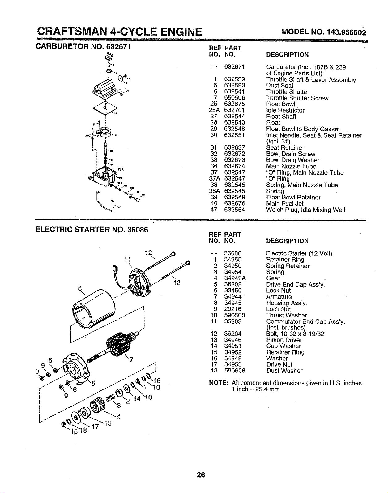
=1 ==== H, H==,HHH H=
ELECTRIC STARTER NO. 36086
IH ======,,,,,,, ,, ,,,,,,,,,,,,,,,,,,,,,,=,,=,=
REF PART
NO. NO.
DESCRIPTION
Carburetor (Inclo187B & 239
of Engine Parts List)
Throttle Shaft & Lever Assembly
Dust Seat
Throttle Shutter
Throttle Shutter Screw
FIoat Bowl
Idle Restdctor
Float Shaft
Float
Float Bowl to Body Gasket
Inlet Needle, Seat & Seat Retainer
(Inclo 31)
Seat Retainer
Bow[ Drain Screw
Bowl Drain Washer
Main Nozzle Tube
"O" Ring, Main Nozzle Tube
"O" Ring
Spring, Main Nozzle Tube
Spring
Float Bowl Retainer-
Main Fuel Jet
Welch Plug, Idle Mixing Well
DESCRIPTION
6
9\
9
- - 36086 Electric Starter (12 Volt)
1 34955 Retainer Ring
2 34950 Spring Retainer
3 34954 Spring
4 34949A Gear
5 36202 Drive End Cap Ass'y_
6 33450 Lock Nut
7 34944 Armature
8 34945 Housing Ass'yo
9 29216 Lock Nut
t0 590500 Thrust Washer
11 36203 Comrnutator End Cap Ass'y.
(lncL brushes)
12 36204 Bolt, 10-32x 3-19/32"
13 34946 Pinion Driver
14 34951 Cup Washer
15 34952 Retainer Ring
16 34948 Washer
17 34953 Drive Nut
18 590608 DustWasher
NOTE: All component dimensions given in U_S. inches
1 inch = 25.4 mm
26
CRAFTSMAN 4-CYCLE ENGINE MODELNO.143.966502
II1'1
I IIIIIII IIII I[11111111111
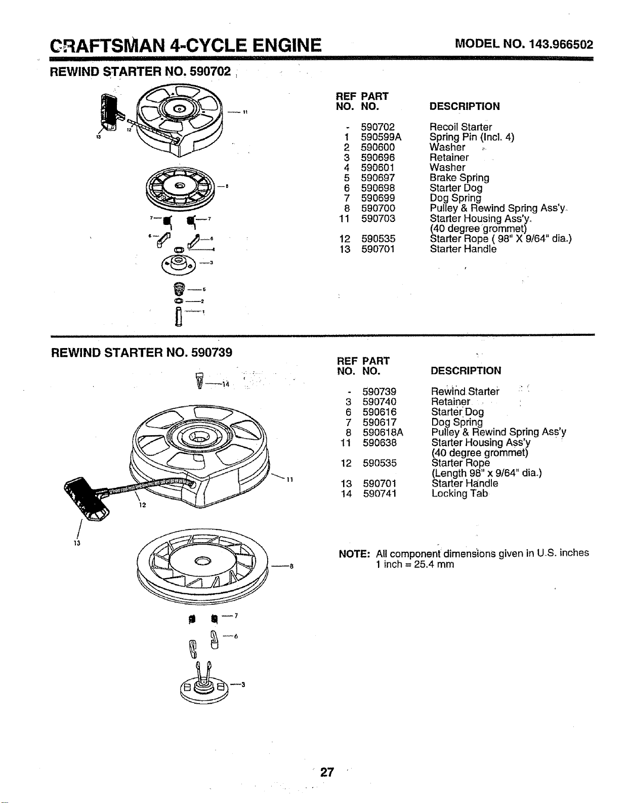
REWIND STARTER NO. 590702
--1t
O--2
REF PART
NO. NO. DESCRIPTION
590702 Recoil Starter
1 590599A Spring Pin (Incl. 4)
2 590600 Washer ._
3 590696 Retainer
4 590601 Washer
5 590697 Brake Spring
6 590698 Starter Dog
7 590699 Dog Spring
8 590700 Pulley & Rewind Spring Ass y.
'11 590703 Starter Housing Ass'y.
(40 degree grommet)
12 590535 Starter Rope ( 98" X 9/64" dia,)
13 590701 Starter Handle
REWIND STARTER NO. 590739
REF PART
NO. NO. DESCRIPTION
590739 ReWind Starter :: _:
3 590740 Retainer . ,
6 590616 StarterlDog
7 590617 Dog Spring
8 590618A Pulley & Rewind Spring Ass'y
11 590638 Starter Housing ASs'y '
(40 degree grommet)
12 590535 Starter Rope
(Length 98" x 9/64" dial)
13 590701 Starter Handle
14 590741 Locking Tab
13
! II11-7
--8
NOTE: Ail component dimens'ions given in U.S. inches
1 inch = 25.4 mm
27
OWNER'S
MANUAL
'i I
MODEL NO.
917.376360
IF YOU NEED
REPAIR SERVICE
OR PARTS:
FOR REPAIR SERVICE, CALL
THIS TOLL FREE NUMBER:
1-800-4-REPAIR
(1-800-473*7247)
FOR REPLACEMENT PARTS
INFORMATION AND
ORDERING, CALL THIS
TOLL FREE NUMBER:
1-800-FON-PART
(1-800-366-7278)
CRAFTS
6.5 HORSEPOWER
22" REAR DISCHARGE
POWER PROPELLED
ROTARY LAWN MOWER
Each lawn mower has its own model number. Each en-
gine has its own model number:,
The model number for your lawn mower will be found on a
decal attached to the rear of the lawn mower !lousing.
The model number for your engine will be found on the
blower housing of the engine.
All parts listed herein may be ordered from any Sears,
Roebuck and Co. Service CenterJDepartment and most
Retail Stores.
WHEN ORDERING REPAIR PARTS, ALWAYS GIVE THE
FOLLOWING INFORMATION:
• PRODUCT - LAWN MOWER
= MODEL NUMBER - 917.376360
• ENGINE MODEL NO. - 143.966502
= PART NUMBER
• PART DESCRIPTION
Your Sears merchandise has added value when you
consider' Sears has service units nationwide staffed with
Sears trained technicians.., professional technicians
specifically trained to insure that we meet our pledge to
you, we service what we sell.
28