Loading ...
Loading ...
Loading ...
18
Requirements
Installation
Instructions
Dryer Use
Dryer Care
Troublesho
o
ting
Safety and
Precautions
Installation
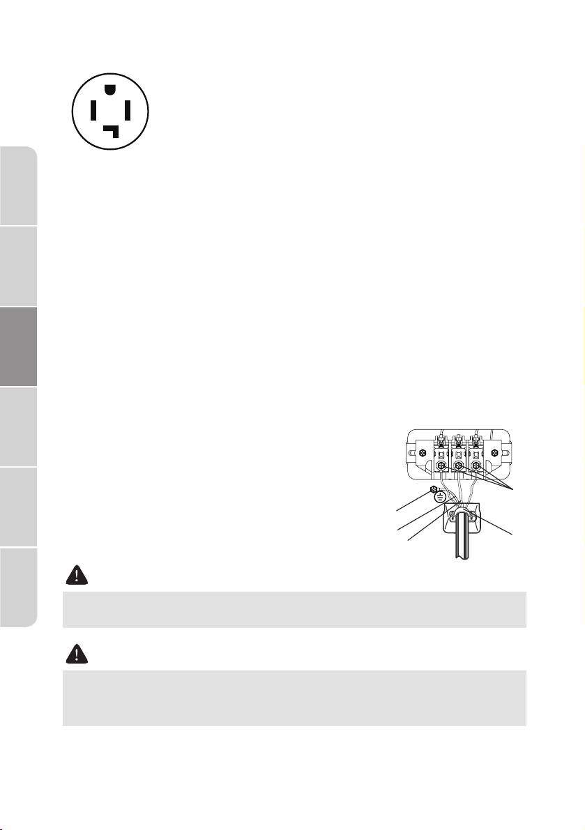
4-wire system instructions:
A. Terminal block screw
B. External ground connector
C. 3/4" (1.9cm) UL-listed strain relief
D. Green or bare copper wire of the power cord
E. Neutral wire (white or center wire)
4-Wire system connections
Connect the ground wire (green or unwrapped) of the power cord to
the external ground conductor screw.
Remove the center terminal block screw and Connect the neutral
wire (white or center wire) of the power cord to the center terminal
screw of the terminal block. Be sure to cross the screw through the
terminal ring and tighten the screw.
Remove the two side terminal block screw and connect the other
wires to the outer terminal screws. Be sure to cross the screw through
the terminal ring and tighten the screw.
Tighten the strain relief screws.
Insert the tab of the terminal block cover into your dryer's rear panel
slot. Secure the cover with a screw.
•
•
•
•
•
AVERTISSEMENT
Ring-type terminals are recommended. If using strip terminals, make
sure they are tightened.
AVERTISSEMENT
U.S. Models:
Risk Of Electric Shock - All U.S. models are produced for a 3-WIRE
SYSTEM CONNECTION.
Then choose a 4-wire power supply cord with ring
terminals and UL listed strain relief. The 4-wire power
supply cord, at least 4.92 ft. (1.5 m) long, must have 4
10-gauge solid copper wires and match a 4-wire
receptacle of NEMA Type 14-30 R, rated 120/240V,
min 10A. The ground wire (ground conductor) may
be either green or bare.The neutral conductor must
be identified by a white color.
4-Wire
receptacle
(14-30R)
Four wire outlet
C
B
A
D
E
Loading ...
Loading ...
Loading ...