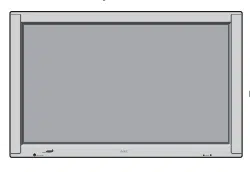

PlasmaSync 3300 Multimedia Monitor
Printed in Japan
78xxxxxxx
MultiSync is a registered trademark of NEC Technologies, Inc. in the U.S.A.
NEC is registered trademark of NEC Corporation.
1993 by NEC Technologies, Inc.
NEC Technologies, Inc.
1250 N. Arlington Heights Road, Suite 500
Itasca, Illinois 60143-1248
PlasmaSync 3300 Multimedia Monitor
PlasmaSync
User's Manual

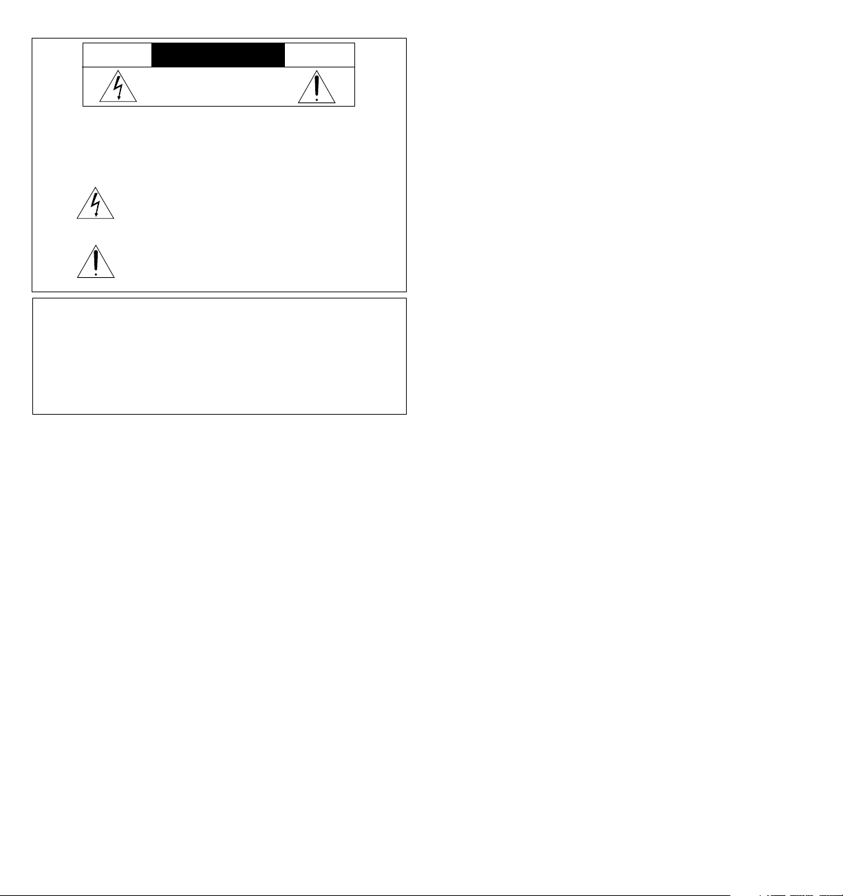
CAUTION
RISK OF ELECTRIC SHOCK
DO NOT OPEN
WARNING
TO PREVENT FIRE OR SHOCK HAZARDS, DO NOT EXPOSE THIS UNIT TO
RAIN OR MOISTURE. ALSO DO NOT USE THIS UNIT'S POLARIZED PLUG
WITH AN EXTENSION CORD RECEPTACLE OR OTHER OUTLETS, UNLESS
THE PRONGS CAN BE FULLY INSERTED. REFRAIN FROM OPENING THE
CABINET AS THERE ARE HIGH-VOLTAGE COMPONENTS INSIDE. REFER
SERVICING TO QUALIFIED SERVICE PERSONNEL.
CAUTION: TO REDUCE THE RISK OF ELECTRIC SHOCK, DO
NOT REMOVE COVER. NO USER-SERVICEABLE
PARTS INSIDE. REFER SERVICING TO QUALIFIED
SERVICE PERSONNEL.
This symbol warns the user that uninsulated voltage within the unit may
have sufficient magnitude to cause electric shock. Therefore, it is danger-
ous to make any kind of contact with any part inside of this unit.
This symbol alerts the user that important literature concerning the opera-
tion and maintenance of this unit has been included. Therefore, it should
be read carefully in order to avoid any problems.
DOC compliance Notice
This Class A digital apparatus meets all requirements of the Canadian
Interference-Causing Equipment Requlations.
Warnings and Safety Precaution
The NEC Multimedia monitor PlasmaSync 3300 is designed and manu-
factured to provide long, trouble-free service. No maintenance other
than cleaning is required. Use a soft dry cloth to clean the panel. Never
use solvents such as alcohol or thinner to clean the panel surface.
For operating safety and to avoid damage to the unit, read carefully
and observe the following instructions.
To avoid shock and fire hazards:
1. Provide adequate space for ventilation to avoid internal heat build-
up. Do not cover rear vents or install in a closed cabinet or shelves.
The unit is equipped with cooling fans. If you enclose the unit in a
cabinet or rack, be sure there is adequate space at the top of the
unit to allow heated air to rise and escape.
If the monitor becomes too hot, the overheat protector will be acti-
vated and the monitor will be turned off. If this happens, turn off the
power to the monitor and unplug the power cord. If the room where
the monitor is installed is particularly hot, move the monitor to a
cooler location, and wait for the monitor to cool for 60 minutes. If the
problem persists, contact your NEC dealer for service.
2. Do not use the power cord polarized plug with extension cords or
outlets unless the prongs can be completely inserted.
3. Do not expose unit to rain or moisture.
4. Avoid damage to the power cord, and do not attempt to modify the
power cord.
5. Unplug unit during electrical storms or if unit will not be used over a
long period.
6. Do not open the cabinet which has potentially dangerous high volt-
age components inside. If the unit is damaged in this way the war-
ranty will be void. Moreover, there is a serious risk of electric shock.
7. Do not attempt to service or repair the unit. NEC is not liable for any
bodily harm or damage caused if unqualified persons attempt ser-
vice or open the back cover. Refer all service to authorized NEC Ser-
vice Centers.
To avoid damage and prolong operating life:
1. Use only with 120V 60Hz AC power supply. Continued operation at
line voltages greater than 120 Volts AC will shorten the life of the unit,
and might even cause a fire hazard.
2. Handle the unit carefully when installing it and do not drop.
3. Locate set away from heat, excessive dust, and direct sunlight.
4. Protect the inside of the unit from liquids and small metal objects. In
case of accident, unplug the unit and have it serviced by an autho-
rized NEC Service Center.
5. Do not hit or scratch the panel surface as flaws on the surface may
result.
WARNING
This equipment has been tested and found to comply with the limits for
a Class A digital device, pursuant to Part 15 of the FCC Rules. These
limits are designed to provide reasonable protection against harmful
interference when the equipment is operated in a commercial
environment. This equipment generates, uses, and can radiate radio
frequency energy and, if not installed and used in accordance with the
instruction manual, may cause harmful interference to radio
communications. Operation of this equipment in a residential area is
likely to cause harmful interference in which case the user will be
required to correct the interference at his own expense.
MISE EN GARDE: AFIN DE REDUIRE LES RISQUES D’ELECTRO-
CUTION, NE PAS DEPOSER LE COUVERCLE, IL
N’Y A AUCUNE PIECE UTILISABLE A L’INTERIEUR
DE CET APPAREIL. NE CONFIER LES TRAVAUX
D’ENTRETIEN QU’A UN PERSONNEL QUALIFIE.
Ce symbole a pour but de prévenir l’utilisateur de la présence
d’une tension dangereuse, non isolée se trouvant à l’intérieur de
l’appareil. Elle est d’une intensité suffisante pour constituer un
risque d’électrocution. Eviter le contact avec les pièces à
l’intérieur de cet appareil.
Ce symbole a pour but de prévenir l’utilisateur de la présence
d’importantes instructions concernant l’entretien et le
fonctionnement de cet appareil. Par conséquent, elles doivent
être lues attentivement afin d’éviter des problèmes.
AVERTISSEMENT
AFIN DE REDUIRE LES RISQUES D’INCENDIE OU D’ELECTROCUTION, NE PAS
EXPOSER CET APPAREIL A LA PLUIE OU A L’HUMIDITE. AUSSI, NE PAS
UTILISER LA FICHE POLARISEE AVEC UN PROLONGATEUR OU UNE AUTRE
PRISE DE COURANT SAUF SI CES LAMES PEUVENT ETRE INSEREES A FOND.
NE PAS OUVRIR LE COFFRET, DES COMPOSANTS HAUTE TENSION SE
TROUVENT A L’INTERIEUR. LAISSER A UN PERSONNEL QUALIFIE LE SOIN DE
REPARER CET APPAREIL.
ATTENTION
RISQUE D’ELECTROCUTION
NE PAS OUVRIR
DOC avis de conformation
Cet appareil numérigue de la classe A respecte toutes les exigences du
Réglement sur le Matériel Brouilleur du Canada.
Mises en garde et précautions de sécurité
Le moniteur Multimédia PlasmaSync 3300 de NEC est conçu et fabriqués
pour assurer une longue durée de service sans problèmes. Aucun entretien
à l’exception du nettoyage n’est nécessaire. Utiliser un chiffon doux et sec.
Ne jamais utiliser de détergents puissants ou des solvents, tel que l'alcool
ouun diluant pour nettoyer le moniteur à écran plasma.
Pour un fonctionnement sûr et afin d’éviter d’endommager l’appareil, lire
attentivement et respecter les instructions suivantes.
Afin d’éviter tout risque d’électrocution et d’incendie:
1. Réserver un espace libre suffisant pour la ventilation afin d’éviter une
accumulation de chaleur interne. Ne pas couvrir les trous d’aération
arrière ou installer l’appareil dans un coffret fermé ou sur une étagère.
L’appareil est équipé d’ailettes de refroidissement sur le dessus. Si
l’appareil est logé dans un coffret ou sur une étagère, s’assurer qu’il y a
un espace libre suffisant pour la dissipation de la chaleur. Si l’appareil est
posé sur un coffret ou une étagère, la température doit être maintenue
en dessous de 40°C.
2. Ne pas utiliser la fiche polarisée du cordon d’alimentation avec des
prolongateurs ou des prises de courant, sauf si les lames peuvent être
insérées à fond.
3. Ne pas exposer à la pluie ou à l’humidité.
4. Eviter d’endommager le cordon d’alimentation, et ne pas modifier le
cordon d’alimentation.
5. Débrancher l’appareil pendant les tempêtes ou si l’appareil n’est pas
utilisé pendant une longue période.
6. Ne pas ouvrir le coffret. Des composants de haute tension se trouvent à
l’intérieur. Si l’appareil est endommagé de cette manière, la garantie
devient caduque. De plus, il y a risque d’électrocution.
7. Ne pas essayer de réparer ou entretenir l’appareil soi-même. NEC ne saura
être tenu pour responsable pour toute blessure ou dommage causé par
des personnes non qualifiées qui essayent de réparer ou d’ouvrir le
couvercle arrière. Confier toute réparation à un centre de service agréé
NEC.
Pour éviter des dommages et prolonger la durée de service de l’appareil:
1. N’utiliser qu’une source d’alimentation de 120 V 60 Hz CA. Le fait d’utiliser
l’appareil en continu à des tensions de ligne supérieures à 120 Volts CA
réduit sa durée de vie et risque de provoquer un incendie.
2. Manipuler l’appareil avec soin pendant son déplacement et ne pas le
faire tomber.
3. Eloigner l’appareil des endroits chauds, très poussiéreux et exposés en plein
soleil.
4. Eviter que des liquides et des petits objets métalliques pénètrent à
l’intérieur de l’appareil. En cas d’accident, débrancher l’appareil et le
confier à un centre de service agréé NEC.
5. Ne pas frapper ou rayer la surface de la écran plasma, car des défauts
risquent de se produire sur la surface de la écran plasma.

Introduction ......................................................................................................................... 1
Introduction to the PlasmaSync 3300...................................................................................... 1
Feature Highlights ...................................................................................................................... 1
Part Names and Functions ................................................................................................. 3
Front View................................................................................................................................... 3
Rear View /Terminal Board....................................................................................................... 5
Remote Control Unit................................................................................................................ 11
Battery Installation and Replacement / Remote Control Cautions / Operating Range .................. 15
Functions of DIP SW ........................................................................................................... 15
Functions and Settings of DIP SW 1........................................................................................ 17
Functions and Settings of DIP SW 2........................................................................................ 19
Installation.......................................................................................................................... 21
External Component Connections ....................................................................................... 21
Video Signal Connections ...................................................................................................... 21
RGB Signal Connections ......................................................................................................... 21
Mini D-SUB 15 Pin RGB Signal Composition ........................................................................... 22
Typical Connection Example ................................................................................................. 25
External Speaker Connections............................................................................................... 27
CONTENTS
Controls/Adjustments ....................................................................................................... 29
Power ........................................................................................................................................ 29
Video Signal Input Settings ..................................................................................................... 29
Video Signal, Picture Adjustments ......................................................................................... 27
RGB Signal Input Settings ........................................................................................................ 30
RGB Signal, Picture Adjustments ............................................................................................ 31
Volume Control ....................................................................................................................... 31
OSM Controls ..................................................................................................................... 31
Direct Control Screen.............................................................................................................. 32
Accessing OSM/Main menu .................................................................................................. 33
White Balance Controls .......................................................................................................... 34
Language Select/OSM Location Control ............................................................................. 35
OSM Turn Off Time/OSM Gain Control .................................................................................. 36
Display Mode/Position Controls ............................................................................................. 37
Auto Picture Control (Picture ADJ/Fine Picture) .................................................................. 38
Visual Controls/Volume Control............................................................................................. 39
Normal ...................................................................................................................................... 40
External Control Function ................................................................................................. 41
Sigal Identification Flowchart........................................................................................... 43
Troubleshooting ................................................................................................................. 45
Specifications .................................................................................................................... 47
Dimensions ............................................................................................................................... 51
Limited Warranty ............................................................................................................... 53

Feature Highlights
The OSM (On Screen Manager) controls have made the monitor' s Digital
Control System easier to use by providing menus on screen. Pressing the
PROCEED key turns on OSM. You' ll find it easy to navigate through the
menu that appears, and icons show you how the controls work.
IPM (Intelligent Power Manager) is an innovative power saving utility that
complies with the EPA' s Energy Star requirements . Energy Star products
use 30 watts or less when in the main power saving mode.
When in the maximum power-down mode, the PlasmaSync 3300
monitor will consume approximately 10% of the total power drawn under
normal operation. This innovation adds up to 70% energy savings, longer
monitor life, environmental protection, reduced emissions, and reduced
air conditioning costs of the work environment.
Monitors follow the Video Electronics Standards Association (VESA)
approved DPMS power-down signaling method. VESA' s Display Power
Management Signaling(DPMS) method which is endorsed by the EPA is
the power-down process a system should use to communicate to the
monitor to save power. Power-down functions can only be utilized with
an energy star system or video card which adhere to the VESA DPMS
standard. By using the monitor' s horizontal and vertical SYNC signals, the
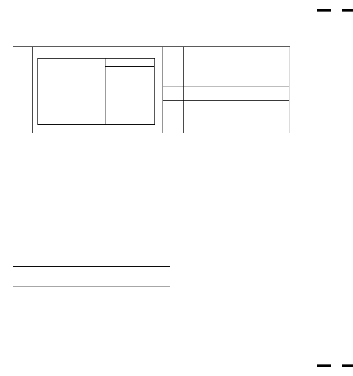
monitor can be prompted into the different IPM modes. The following is
the description of the LED indicator for the IPM power saving modes:
Mode LED Indicator Power Saving
On Green None
Standby Yellow Minimum
(Quickest Recovery)
Suspend Orange Moderate
(EPA< 30 Watts, Moderate Recovery)
Off Orange Maximum
(IPM Mode) (Slowest Recovery)
Off No Light No Power Used
(Power Switch, Off)
(Fully Off)
1
2
OSM and IPM are trademarks of NEC Technologies, Inc.
IBM PC/AT, PS/2 and VGA are registered trademarks of International
Business Machines Corporation.
Apple and Macintosh are registered trademarks of Apple Computer,
Inc.
Microsoft is a registered trademark of Microsoft Corporation. Windows is
a trademark of Microsoft Corporation.
Introduction
Introduction to the PlasmaSync 3300
Congratulations on your purchase of NEC' s PlasmaSync 3300
multimedia monitor which includes Microsoft' s Plug and Play
compatibility. Just plug your PlasmaSync 3300 monitor into a Plug and
Play compatible system, and your monitor is automatically ready to run
at it' s optimum performance. Other examples of features that
enhance your multimedia monitor performance are the On-Screen
Manager(OSM
TM
) controls and the Intelligent Power Manager(IPM
TM
)
System.
The Intelligent Power Manager(IPM
TM
) System follows the United States
government' s Environmental Protection Agency (EPA) guidelines. The
IPM System increases the monitor' s life and saves energy and costs by
powering down when not in use.
The MultiSync PlasmaSync 3300 multimedia monitor incorporates NEC' s
famous multiple frequency technology. You are provided with a choice
of multiple operating platforms and a vast array of graphic standards.
Now, many resolution upgrades are possible without a new monitor.
A wide range of graphics standards is supported by the MultiSync
PLASMASYNC 3300 multimedia monitor including:
*
1
NTSC
*
1
PAL
*
1
SECAM
*
2
VGA at 640 x 400 • 70Hz
VGA at 640 x 480 • 60 and 75Hz
*
1
VESA at 640 x 480 • 60, 72 and 75Hz
*
1
VESA at 800 x 600 • 56.2 and 60.3Hz
*
1
This signal is converted into a 640 x 480 image.
*
2
indiates that only 400 lines at vertical center are
displayed.
And Macintosh resolutions such as:
640 x 480 • 66.6Hz
PLUG and PLAY
Plug and Play is the new Microsoft solution with Windows 95 to provide
automatic peripheral connections without confusing and time-
consuming setup. NEC developed the monitor's Plug and Play capability
that allows your Plug and Play compatible system to automatically
identify, configure, and optimize the monitor connected to it. The
PlasmaSync 3300 multimedia monitor automatically tells the system its
identification and capabilities. NEC' s partnership with Microsoft provides
you with simple installation, setup, and service.
Contents of the Package
The following lists all of the items included in your multimedia monitor
package. Please save the original box and packing materials for future
transportation or shipment of this monitor.
1. PlasmaSync 3300 multimedia monitor
2. Power cord
3. Remote control unit with remote cable and two AA batteries.
4. User' s manual
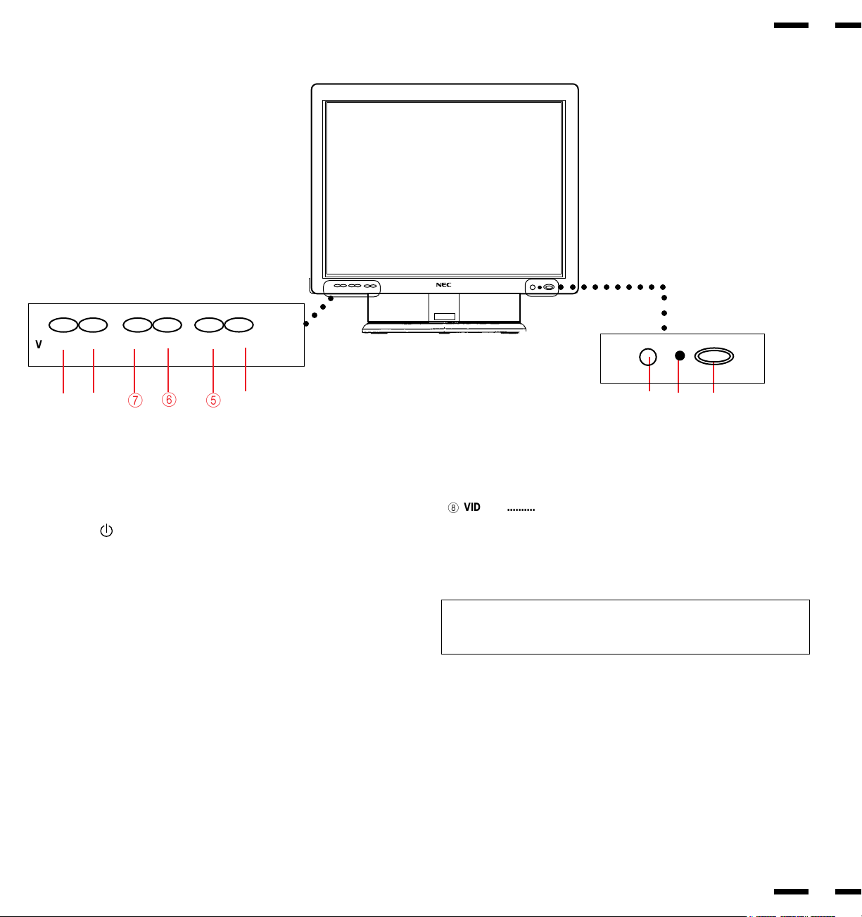
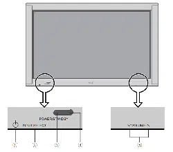
1 POWER .............................. Press to power the monitor on and off.
2
STANDBY /POWER
............
Lights green during normal operation.
Lights orange when the monitor is in standby
mode.
3
Remote Sensor Window ........
Receives infrared signal from the remote control
unit.
4
EXIT .........................................
Press to exit the OSM controls in the main menu.
Press to exit to the previous menu in a submenu.
5
PROCEED................................
Press to access OSM. Press to proceed to the
selected menu choice (indicated by the arrow).
Press to move the arrow down to select one of
the choices.
6
RGB 2 ......................................
Press to select the RGB source that is connected
to the RGB 2 input terminals (BNC type).
7
RGB 1 ......................................
Press to select the RGB source that is connected
to the RGB 1 input terminal (mini D-SUB 15 pin
type).
Part Names and Functions
Front View
32 1
3
4
Indicator
○○○
6
5
VIDEO 1/VIDEO 2/RGB 1/RGB 2/PROCEED/EXIT
○○ ○○○
4
98
7
○○○○○○○○○○
8
VIDEO 2 ...................................
Press to select the video source that is
connected to the VIDEO 2 input terminal
(BNC type or S-VIDEO 2 IN).
9
VIDEO 1 ...................................
Press to select the video source that is
connected to the VIDEO 1 input terminal
(BNC type or S-VIDEO 1 IN).
NOTE: S-VIDEO IN terminals will take preference over VIDEO IN termi-
nals when the video source is connected to each terminal and VIDEO 1
or 2 selected.
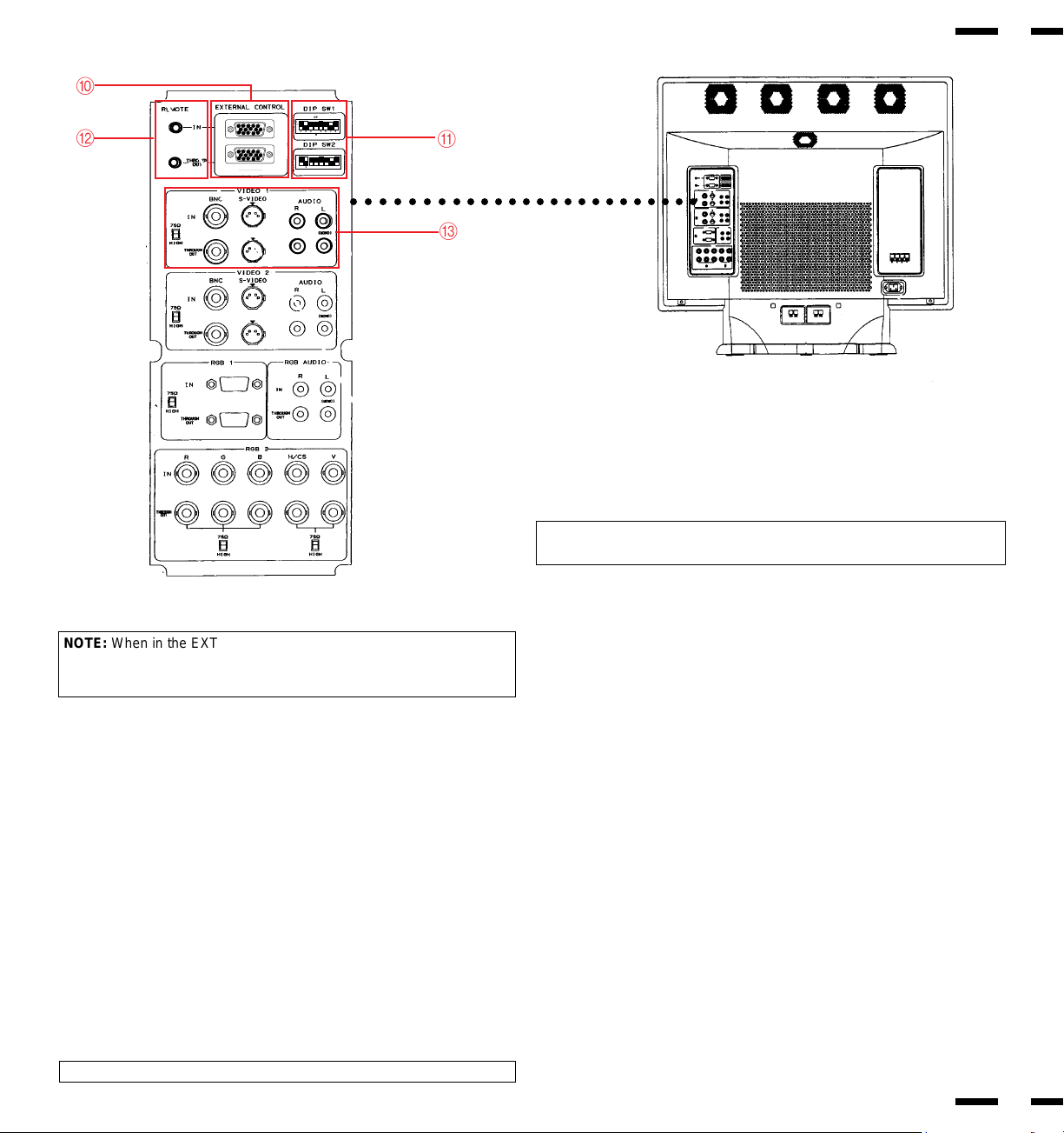
Terminal Board
5
6
0 EXTERNAL CONTROL
EXTERNAL CONTROL IN (mini D-SUB 15 PIN).....This terminal is used when
power ON/OFF, input selection, AUDIO MUTE and PICTURE MUTE are
operated externally (by external control). See also page 41 for external con-
trol port pin assignments.
NOTE: Select EXT. CONTROL ON by setting pin No. 7 of DIP SW 1 to
ON when operating the monitor by external control.
○○○○○○○○○○○○○○○○○○○○○○○○○
A
0
B
C
NOTE: When in the EXT. CONTROL mode, the following operations of
the supplied remote control are not possible: Power control ON/ OFF,
Input selection, and Audio mute ON/OFF.
EXTERNAL CONTROL OUT (mini D-SUB 15 PIN)..... Connect to a second moni-
tor' s EXTERNAL CONTROL input to relay the signal input at the EXTER-
NAL CONTROL IN.
The EXTERNAL CONTROL THROUGH OUT terminal is used to connect
several monitors together (up to 50) and allows all of the monitors to be
controlled by one external control. No. 7 pin (EXT. CONTROL) of DIP
SW 1 must be set to the ON position on all of the monitors.
A DIP Switches
DIP SW 1.....This DIP switch sets various conditions of the monitor. See
pages 17 and 18 for more details.
DIP SW 2.....This DIP switch sets Sync. Control and the Intelligent Power
Manager. Set all eight pins to the OFF positions during normal operation.
See pages 19 and 20 for more details.
B REMOTE IN/OUT..... When the supplied remote control is used in the
wired condition, connect the supplied remote cable to the REMOTE IN termi-
nal. The REMOTE OUT terminal is used to connect several monitors to-
gether and allows all of the monitors to be controlled by one remote control.
NOTE: Up to 50 monitors can be connected in the serial connection.
C VIDEO 1
VIDEO 1 IN (BNC type).....Connect to a video output of the external source.
S-VIDEO 1 IN.....Connect the S-video source with an S-connector output
here.
THROUGH OUT (BNC type).....Connect to a second monitor' s video input to
relay the video signal input at VIDEO 1 IN.
THROUGH OUT (S-VIDEO).....Connect to a second monitor' s S-connector
input to relay the video signal input at S-VIDEO 1 IN.
75 Ω/HIGH Impedance Select Switch.....Set to "75 Ω" during normal opera-
tion. In multiple connections using VIDEO 1 IN and THROUGH OUT ter-
minals, set to "HIGH" on all but the last monitor. Set to "75 Ω" on the last
monitor only.
AUDIO R IN..... Connect the stereo right channel audio output here.
AUDIO L IN (MONO).....Connect the mono audio or stereo left channel au-
dio output here.
AUDIO R THROUGH OUT.....Connect to a second monitor' s audio right
channel input.
AUDIO L THROUGH OUT .....Connect to a second monitor' s audio left chan-
nel input.
1
2
34
5
11
12
13
1415
6
7
8
9
10
1
2
34
5
11
12
13
1415
6
7
8
9
10
12345678
OPEN
SHORT
ON
“
12345678
OPEN
SHORT
ON
“
7
8
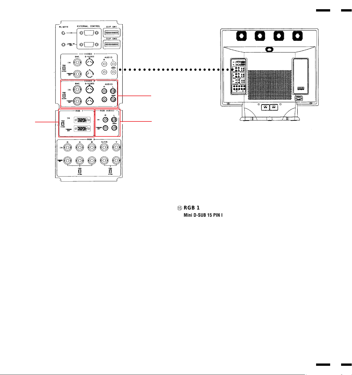
D VIDEO 2
VIDEO 2 IN (BNC type).....Connect the video source' s output here.
S-VIDEO 2 IN.....Connect the S-video source with an S-connector output
here.
THROUGH OUT (BNC type).....Connect to a second monitor' s video input to
relay the video signal input at VIDEO 2 IN.
THROUGH OUT (S-VIDEO).....Connect to a second monitor' s S-connector
input to relay the video signal input at S-VIDEO 2 IN.
75 Ω/HIGH Impedance Select Switch.....Set to "75 Ω" during normal opera-
tion. In multiple connections using VIDEO 2 IN and THROUGH OUT termi-
nals, set to "HIGH" on all but the last monitor. Set to "75 Ω" on the last
monitor only.
AUDIO R IN.....Connect the stereo right channel audio output here.
AUDIO L IN (MONO).....Connect the mono audio or stereo left channel audio
output here.
AUDIO R THROUGH OUT.....Connect to a second monitor' s audio right chan-
nel input.
AUDIO L THROUGH OUT.....Connect to a second monitor' s audio left channel
input.
D
E
F
○○○○○○○○○○○○○○○○○○○○○○○○○
ERGB 1
Mini D-SUB 15 PIN IN.....A15 Pin Analog RGB 1 input terminal compatible
with computers that have a VGA/S-VGA/XGA output signal.
D-SUB 15 PIN THROUGH OUT.....Connect to an RGB INPUT terminal on an-
other monitor.
75 Ω/HIGH Impedance Select Switch.....Set to "75 Ω" during normal operation.
Set to "HIGH" when using the D-SUB 15 PIN THROUGH OUT RGB 1 termi-
nal.
F RGB AUDIO
AUDIO R IN.....Connect the audio right channel output of the RGB source.
AUDIO L IN.....Connect the mono audio or stereo left channel output of the
RGB source.
AUDIO R THROUGH OUT.....Connect to a second monitor' s audio right chan-
nel RGB input.
AUDIO L THROUGH OUT.....Connect to a second monitor's audio left channel
RGB input.
1
2
34
5
11
12
13
1415
6
7
8
9
10
1
2
34
5
11
12
13
1415
6
7
8
9
10
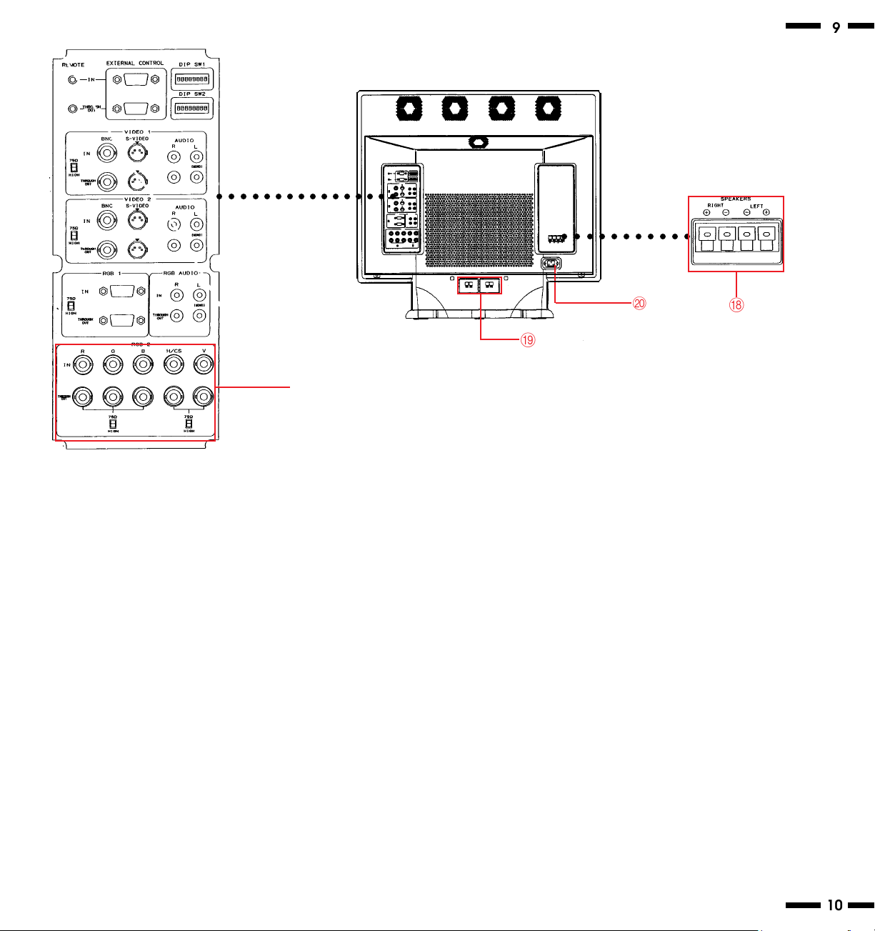
G RGB 2
R, G, B, H/CS and V IN (BNC).....These are analog RGB input terminals.
Connect external components with R, G, B, H/CS, and V output terminals to
these analog RGB input terminals. Be sure that the RGB connection cable is
correctly attached to the corresponding terminals.
R, G, B, H/CS and V THROUGH OUT (BNC)..... Connect to a second monitor's
RGB inputs to relay the RGB signal inputs at R, G, B, H/CS and V IN.
75 Ω/HIGH Impedance Select Switchs for RGB and H/CS&V..... Set to "75 Ω"
during normal operation. In multiple connections using R, G, B, H/CS and V
IN and OUT terminals, set to "HIGH" on all but the last monitor. Set to "75 Ω"
on the last monitor only.
H External Speaker Terminals
+ RIGHT.....Connect RIGHT speaker positive wire here.
- RIGHT.....Connect RIGHT speaker negative wire here.
- LEFT.....Connect LEFT speaker negative wire here.
+ LEFT.....Connect LEFT speaker positive wire here.
I Internal Speaker Terminals
To enable the internal speakers, use the supplied speaker cables to con-
nect between the external speaker terminalsH and here.
J AC Input
Connect the supplied power cord' s three-pin plug here.
G
○○ ○○○○○○○○○○○○○○
○○ ○○○○○○○○○
H
I
9
10
J
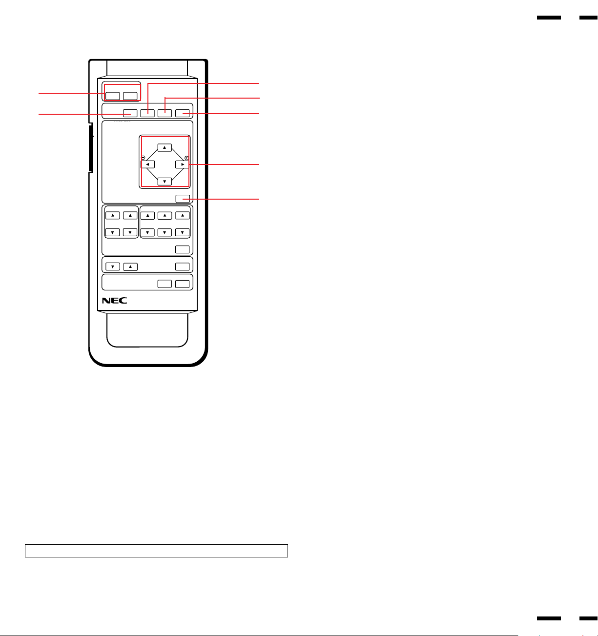
Remote Control Unit
1 POWER ON/OFF ................ Press POWER ON to turn the monitor on
when the STANDBY/POWER indicator is lit
orange.
Press POWER OFF to turn the monitor off
and the monitor will go into the standby condi-
tion.
2 VIDEO 1 .............................. Press to select reception of a conventional
component or S-connector component con-
nected to VIDEO 1 IN terminal.
3 VIDEO 2 .............................. Press to select reception of a conventional
component or S-connector component con-
nected to VIDEO 2 IN terminal.
4 RGB1 .................................. Press to select reception of a component
connected to RGB 1 IN terminal.
5 RGB 2 ................................. Press to select reception of a component
connected to RGB 2 IN terminal.
MULTIMEDIA MONITOR RD-336E
ON
OFF
ON POWER OFF
DEGAUSS
VIDEO1VIDEO2
RGB1
RGB2
WIDTH
HEIGHT
SIDE PIN
SCAN SELECT
POSITION/CONTROL
NORMAL
RASTER CONTROL
RGB/VIDEO
VIDEO
CONTRAST
BRIGHT COLOR TINT
SHARPNESS
NORMAL
VISUAL CONTROL
VOLUME MUTE
EXIT
PROCEED
ON SCREEN
1
2
3
5
4
6
7
11
12
Raster Control
6 POSITION/CONTROL ........ Adjusts the vertical position of the image up
and down, and the horizontal position of the
image from left to right.
CONTROL (. /,).............. Moves the bar in the , or . direction to in-
crease or decrease the adjustment in an
OSM submenu.
CONTROL( / Ä) ............. Moves the arrow up or down to select one of
the controls.
( / Ä / § / ©)
7 NORMAL ............................ This key resets the raster adjustment set-
tings of user changeable memory and recalls
the factory preset data.
NOTE: This can be done to only the signal having the factory preset data.
Ä
Ä
F
D
MULTIMEDIA MONITOR RD-336E
ON
OFF
ON POWER OFF
DEGAUSS
VIDEO1VIDEO2
RGB1
RGB2
WIDTH
HEIGHT
SIDE PIN
SCAN SELECT
POSITION/CONTROL
NORMAL
RASTER CONTROL
RGB/VIDEO
VIDEO
CONTRAST
BRIGHT COLOR TINT
SHARPNESS
NORMAL
VISUAL CONTROL
VOLUME MUTE
EXIT
PROCEED
ON SCREEN
9
0
B
A
C
E
G
I
H
8
13
14
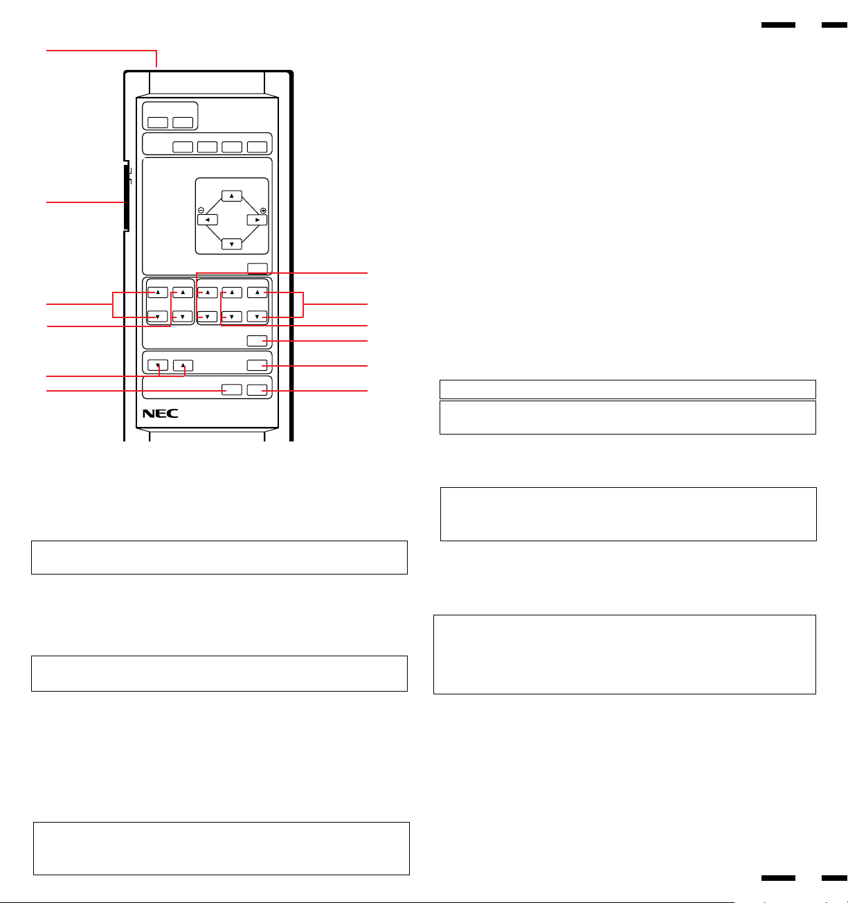
Visual Control
8 RGB/VIDEO
CONTRAST ( / Ä ) ......... Adjusts the image brightness in relation to the
background.
Press and hold for higher contrast.
Press and hold Ä for lower contrast.
9 RGB/VIDEO
BRIGHT ( / Ä ) .............. Adjusts the overall image and screen bright-
ness.
Press and hold for a brighter picture.
Press and hold Ä for a darker picture.
0 COLOR ( / Ä ) ............... Adjusts color intensity of VIDEO display.
Press and hold for more color saturation.
Press and hold Ä for less color saturation.
A TINT ( / Ä ) .................... Adjusts red and green values of VIDEO display.
Press and hold for a greener tint.
Press and hold Ä for a redder tint.
This control does not work for the PAL signal.
B SHARPNESS ( / Ä )...... Adjusts picture detail of VIDEO display.
Press and hold for a sharper picture.
Press and hold Ä for a softer picture.
NOTE:
The COLOR, TINT and SHARPNESS keys work for the VIDEO display only.
NOTE:
The VISUAL CONTROL storing operation is effective only for one input
(VIDEO1, VIDEO2, RGB1 or RGB2).
C NORMAL ............................ This key resets the picture adjustment set-
tings of user changeable memory and recalls
the factory preset data.
NOTE: The CONTRAST, BRIGHT, COLOR, TINT and SHARPNESS ad-
justment level are factory preset at the optimum position.
D VOLUME ( Ä / )............. Adjusts the volume.
Press and hold Ä to decrease sound.
Press and hold to increase sound.
E MUTE.................................. Press to cancel sound ; press again to restore
sound.
NOTE: The other ways to restore sound are to press POWER ON, then OFF
and to press VOLUME keys on the remote control unit.
F EXIT .................................... Press to exit the OSM controls in the main
menu. Press to exit to the previous menu in a
submenu.
G PROCEED .......................... Press to access OSM. Press to proceed to
the selected menu choice (indicated by the
arrow). Press to move the arrow down to se-
lect one of the choices.
NOTE:
• Other control keys than POSITION/CONTROL + / -,
/ Ä, and NORMAL are
not available during the OSM screen display.
• Other control keys than POSITION/CONTROL + / -,
/ Ä, and NORMAL can
be directly to access to each control. OSM controls are not possible in that
case.
HBacklight Switch Set to ON to light up keys from the inside of
the remote control panel.This is useful when
the remote control unit is used in a darkened
room.
NOTE: The backlight key characters may be invisible in a bright-lit room. Make
sure that the backlight switch is OFF when the remote control unit is not used.
If no button operation is made within 30 seconds when the backlight is lit in the
wireless condition, the backlight go off automatically. To turn the backlight on
again, set the switch to the OFF position, then set it to the ON position.
I Remote Jack ...................... Insert the plug of the supplied remote cable
when using the supplied remote control unit
in the wired condition. Connecting the moni-
tor and the remote control unit with the sup-
plied remote cable turns on the backlight in-
dependent of the backlight switch setting
when the monitor is powered on.
Ä
Ä
Ä
Ä
Ä
Ä
Ä
Ä
Ä
Ä
Ä
Ä
Ä
Ä
VIDEO
VIDEO
VIDEO
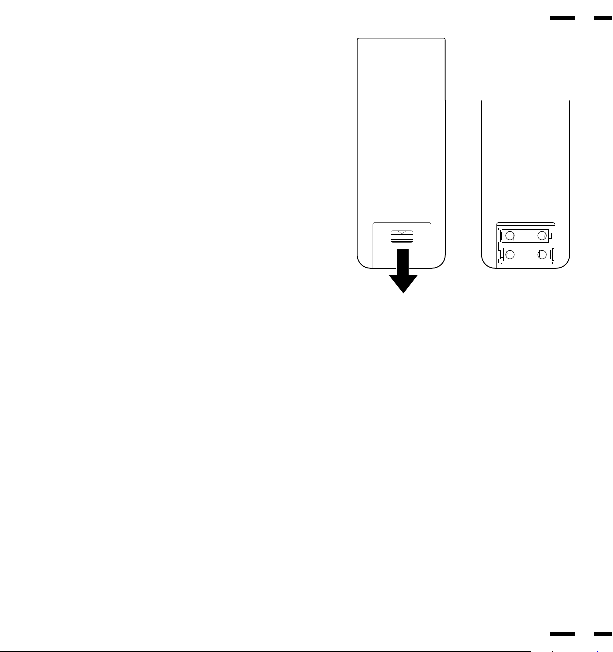
Battery Installation and Replacement
The remote control is powered by two 1.5V AA batteries.
To install or replace batteries:
1.Turn the remote control unit upside down.
2.Press down on the battery compartment grip and slide the com-
partment in the direction of the arrow.
3.Install the two new batteries, making sure that their polarity
matches the (+) (-) diagrams inside the battery compartment. In-
correct polarity could damage the unit.
4.Close the battery compartment cover.
{
|
{
|
Remote Control Cautions
● Do not drop or mishandle the remote control unit.
● Do not get the remote control unit wet. If the remote gets wet,
wipe it dry immediately.
● Avoid heat and humidity.
● When not using the remote control unit for a long period, remove
the batteries.
● Do not use new and old batteries together, or use different types
together.
● Do not take apart the batteries, heat them, or throw them into a
fire.
● When using the remote control unit in the wireless condition, be
sure to unplug the remote cable from the REMOTE IN terminal
on the monitor.
15
16
Operating Range
● The infrared signal operates by line-of-sight up to a distance of ap-
proximately 20 feet and within a 60 degree angle of the Remote
Sensor Window.
● The monitor will not function if there are objects between the Re-
mote and the Sensor Window or if strong light falls on the Sensor
Window. Weak batteries will also prevent the monitor from operat-
ing properly.
No.4
No.5
No.6
No.7
No.8
Pin numbers 4 and 6 are not used. Set the six pins to the OFF position except
Nos. 5 and 8 pin during normal operation.
Pins No. 1, 2 and 3 (POWER ON MODE SET)
Sets the monitor to default to any one of its inputs each time the monitor is
turned on. See table on the above.
This function does not work when the pin No. 1 is set to the OFF position.
The last selected input will be stored.
Pin No. 5 (ON SCREEN DISPLAY )
When this switch is set to ON, the On Screen Manager can be accessed.
Pin No. 7 (EXT. CONTROL)
When this switch is set to ON, the External Control function is activated. See
page 41 for pin assignments.
Pin No. 8 (WIRELESS REMOTE ON/OFF)
When this switch is set to ON, the monitor can be controlled by the wireless
remote control unit.
Functions of DIP SW
Functions and Settings of DIP SW 1
This DIP switch sets various conditions of the monitor.
No.2
---
OFF
ON
OFF
ON
No.1
OFF
ON
ON
ON
ON
No.3
---
OFF
OFF
ON
ON
MODE
DEFEAT
VIDEO 1
VIDEO 2
RGB 1
RGB 2
POWER ON MODE SET
DIP SWITCH
No.1
No.2
No.3
Not Used
ON : On Screen display ON
OFF : On Screen display OFF
Not Used
ON : External control ON
OFF : External control OFF
ON : Wireless remote control ON
OFF : Wireless remote control OFF
18
17
ON: Auto selection for video standard
OFF: Manual selection for video standard
ON: Manually selecting PAL
OFF: Manually selecting NTSC
ON: Manually selecting SECAM
OFF: Manually selecting other
ON: Manually selecting 4.43 NTSC
OFF: Manually selecting other
Not Used
ON : Intelligent Power Manager ON
OFF: Intelligent Power Manager OFF
SYNC. CONTROLNo.1
No.2
DIP SWITCH
No.1
OFF
OFF
ON
ON
No.2
OFF
ON
OFF
ON
MODE
AUTO CONTROL
(Sep, Comp, Sync on G)
MANUAL 1 (Comp. Sync)
MANUAL 2 (Sync. on G)
UNUSED
Functions and Settings of DIP SW 2
This DIP switch is used for Sync. Control and Intelligent Power Manager.
Set all pins to the OFF position except No. 3 pin during normal operation.
No.3
No.4
No.5
No.6
No.7
No.8
Sync. Control ( Pins Nos 1 and 2 )
These pins set Sync. Control.
Set both pins to OFF position during normal operation.
Pin No.1 (Sync. on Green Control)
Set pin No.1 to the ON position and pin No. 2 to the OFF position when sync on
green signals are necessary for synchronization with an external component.
Pin No.2 (Composite Sync Control)
Set pin No. 2 to the ON position and pin No. 1 to the OFF position for H/V
composite sync signals.
NOTE: When pins Nos. 1 and 2 are set to the OFF positions, the monitor
automatically determines if the input signal is separate sync, composite sync
or G-sync signal in this order.
Pin No. 8 (Intelligent Power Manager)
This function saves power.
When Intelligent Power Manager control is on:
When no horizontal sync. signal is present, the STANDBY/POWER indicator is
lit yellow.
When no vertical sync. signal is present, the STANDBY/POWER indicator is lit
orange.
When neither horizontal nor vertical sync. signal is present, the STANDBY/
POWER indicator is lit orange.
NOTE: The Intelligent Power Manager works only for the RGB input. If se-
lecting the VIDEO input, or when connecting to no signal source, the Intelli-
gent Power Manager does not work.
20
19

Installation
External Component Connections
The NEC PlasmaSync 3300 multimedia monitor is designed for convenient
installation with a wide variety of audio, the latest video components and many
data processing devices equipped with analog RGB output.
BNC jack terminals (VIDEO 1 and VIDEO 2) are provided for connection to two
separate external video components, plus S-VIDEO IN (VIDEO 1 and VIDEO
2) terminals for connection to S-connector VCRs.
THROUG-OUT (VIDEO 1 and VIDEO 2) are bridged output terminals that pro-
vide direct signal output of the component connected to VIDEO 1 IN, VIDEO 2
IN, S-VIDEO 1 IN or S-VIDEO 2 IN.
A D-SUB 15 PIN RGB multi-signal input connector automatically scans fre-
quencies between 15.5 kHz and 39.5 kHz. It is compatible with the IBM com-
patibles, and other IBM Compatible Graphics adapters plus any other data
processing devices equipped with analog RGB output.
Video Signal Connections
VIDEO 1 INPUT Connections
1. Connect the external component video output to VIDEO 1 IN.
2. Connect the external component mono audio or stereo left channel audio
output to L AUDIO (MONO).
3.Connect the external component stereo right channel audio output to R
AUDIO.
4.Press VIDEO 1 on the terminal board or the VIDEO 1 key on the remote
control unit.
NOTE: S-VIDEO IN terminals will take preference over VIDEO IN termi-
nals when a component is connected to each terminal and VIDEO 1 or 2
selected.
S-VIDEO 1 INPUT Connections
1. Connect the external components with an S-connector output to S-VIDEO 1
IN.
2. Connect audio terminals as explained in VIDEO 1 INPUT connection previ-
ously.
3. Press VIDEO 1 on the terminal board or the VIDEO 1 key on the remote
control unit.
VIDEO 2 INPUT Connections
1. Connect the external component video output to VIDEO 2 IN.
2. Connect the external component mono audio or stereo left channel audio
output to L AUDIO (MONO).
3. Connect the external component stereo right channel audio output to R
AUDIO.
4. Press VIDEO 2 on the terminal board or the VIDEO 2 key on the remote
control unit.
S-VIDEO 2 INPUT Connections
1. Connect the external component with an S-connector output to S-VIDEO 2
IN.
2. Connect audio terminals as explained in VIDEO 2 INPUT connections previ-
ously.
3. Press VIDEO 2 on the terminal board or the VIDEO 2 key on the remote
control unit.
THROUGH OUT (VIDEO 1) Connections
1. Connect THROUGH OUT 1 BNC or S-VIDEO 1 OUT to external compo-
nents to relay the signal input at VIDEO 1 IN, or S-VIDEO 1 IN.
2. Connect the external component mono audio or stereo left channel audio
input to L AUDIO.
3. Connect the external component stereo right channel audio input to R AU-
DIO.
4. Set the 75Ω/HIGH impedance select switch of the corresponding input sig-
nal on all but the last monitor to “HIGH” position. On only the last monitor set
it to “75Ω” position.
THROUGH OUT (VIDEO 2) Connections
1. Connect THROUGH OUT 2 BNC or S-VIDEO 2 OUT to external component
to relay the signal input at VIDEO 2 IN or S-VIDEO 2 IN.
2. Connect the external component mono audio or stereo left channel audio
input to L AUDIO.
3. Connect the external component stereo right channel audio input to R AU-
DIO.
4. Set the 75Ω/HIGH impedance select switch of the corresponding input sig-
nal on all but the last monitor to “HIGH” position. On only the last monitor set
it to “75Ω” position.
21
22
NOTE: The connection of three PlasmaSync 3300 monitors or more with
THROUGH OUT (VIDEO 1 or 2) terminals may degrade image quality.
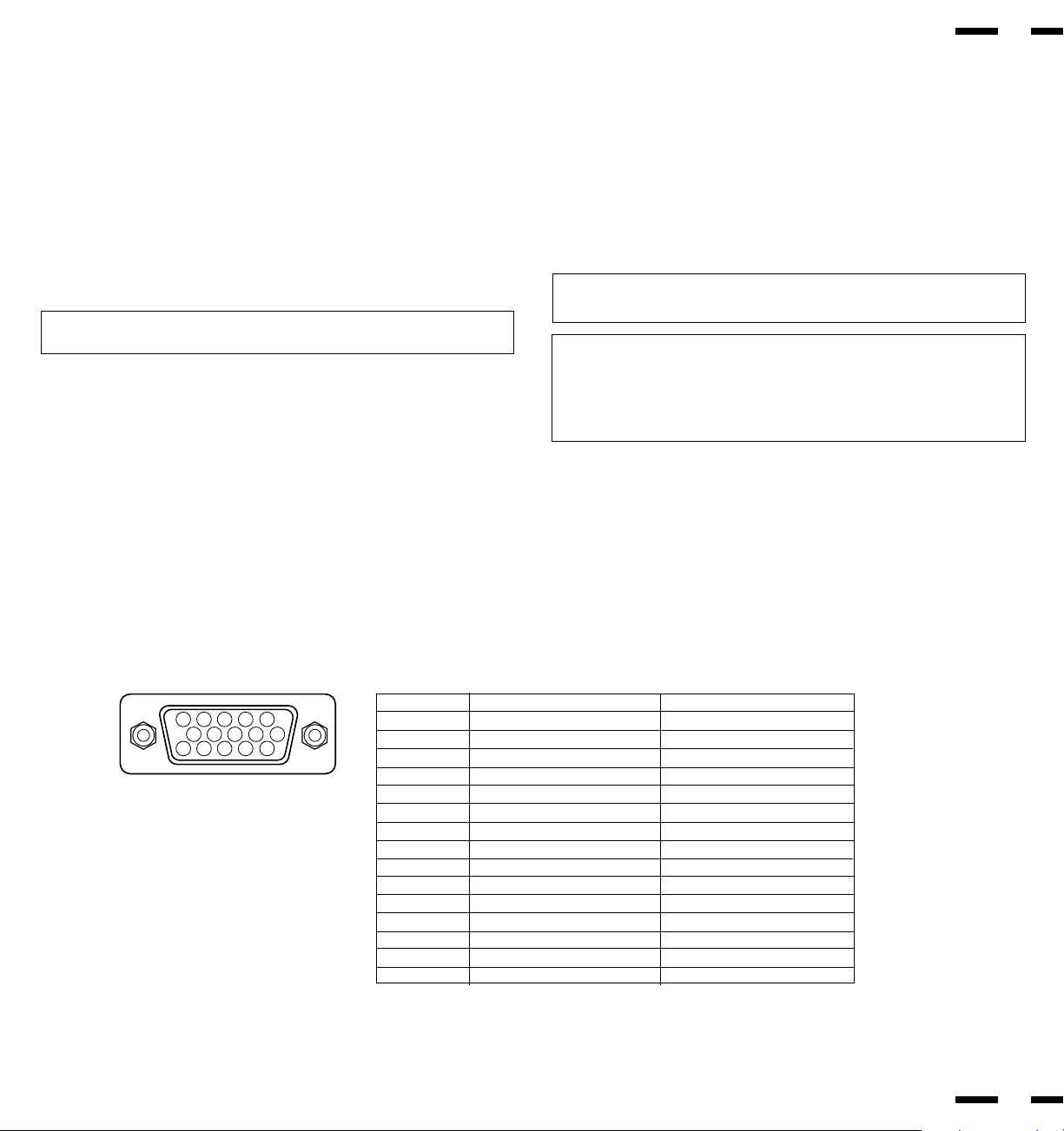
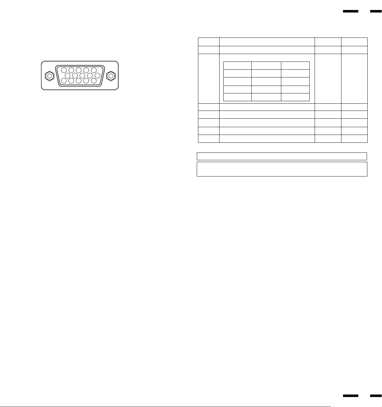
Mini D-Sub 15 Pin RGB Signal Composition
Pin Assignments and Signal Levels for 15 pin RGB (Analog)
1
2
34
5
11
12
13
1415
6
7
8
9
10
Signal to be connected Loop through output
RED RED
GREEN or Sync. on Green GREEN or Sync. on Green
BLUE BLUE
GND GND
GND GND
RED (GND) RED (GND)
GREEN (GND) GREEN (GND)
BLUE (GND) BLUE (GND)
No Connection No Connection
SYNC (GND) SYNC (GND)
GND GND
SDA No connection
H. or Composite sync H. or Composite sync
V.SYNC V.SYNC
SCL No connection
Pin No.
1
2
3
4
5
6
7
8
9
10
11
12
13
14
15
RGB Signal Connections
RGB 1 INPUT Connections
Mini D-SUB 15 Pin RGB Connector.
1. Connect external components or computers having RGB output to the mini
D-SUB 15-Pin connector.
2. Connect the external RGB component mono audio or stereo left channel
audio output to L RGB AUDIO IN (MONO).
3. Connect the external RGB component stereo right channel audio output to
R RGB AUDIO IN.
RGB 2 INPUT Connections
Connect external components with R.G.B.H/CS and V output to the R.G.B.H/
CS and V analog input terminals.
NOTE: ''Plug and Play'' is not available during use of the RGB 2 BNC termi-
nals.
THROUGH OUT (RGB 1) Connections
Monitor Connection
Connect mini D-SUB 15 PIN THROUGH OUT to an RGB input connector of
other monitors.
THROUGH OUT (RGB 2) Connections
1. Connect the R.G.B.H/CS and V THROUGH OUT terminals to relay the sig-
nal input at the R.G.B.H/CS and V IN terminals.
24
23
2. Set all the 75Ω/HIGH impedance select switches on all but the last monitor
to “HIGH” position. On only the last monitor set all of them to “75Ω” position.
NOTE: The connection of three PlasmaSync 3300 monitors or more with
THROUGH OUT (RGB 1 or 2) terminals may degrade image quality.
NOTE: ''Plug and Play'' is available only for the monitor connected directly
to a personal computer with the D-Sub 15 PIN IN RGB connector. Therefore,
''Plug and Play'' does not work for monitors connected with the THROUGH
OUT terminal. This is because only the RGB video, the horizontal, or the
vertical sync. signal is output from the THROUGH OUT terminals.
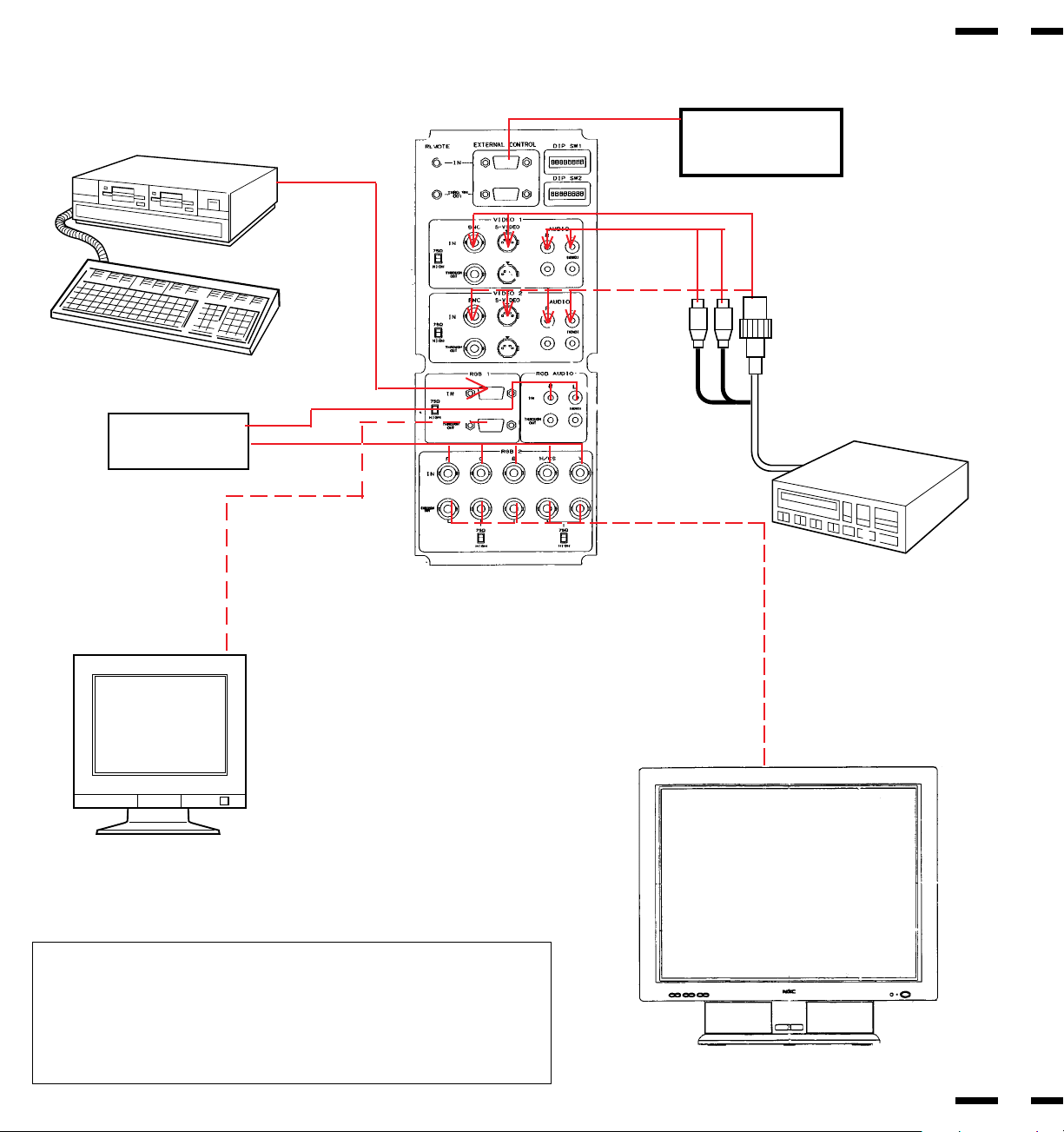
Typical Connection Example
EXTERNAL
CONTROL
To mini D-SUB 15
Pin input
To EXTERNAL CONTROL
(mini D-SUB 15 Pin input)
PlasmaSync 3300
25
26
To VIDEO IN R, L, inputs
CAMERA, VIDEO COPY
STAND OR
MULTIMEDIA APPLICATION
IBM PC OR COMPATIBLES
PlasmaSync 3300
NEC MULTISYNC OR
PC-COMPATIBLE
MONITOR
RGB equipment
To R,G,B,H/CS
and V inputs
(BNC)
NOTE:
•PlasmaSync 3300 does not support PAL/SECAM on a scan
converter.
•We do not recommend to use a scan converter for NTSC signal.
A use of the scan converter degrades picture quality.
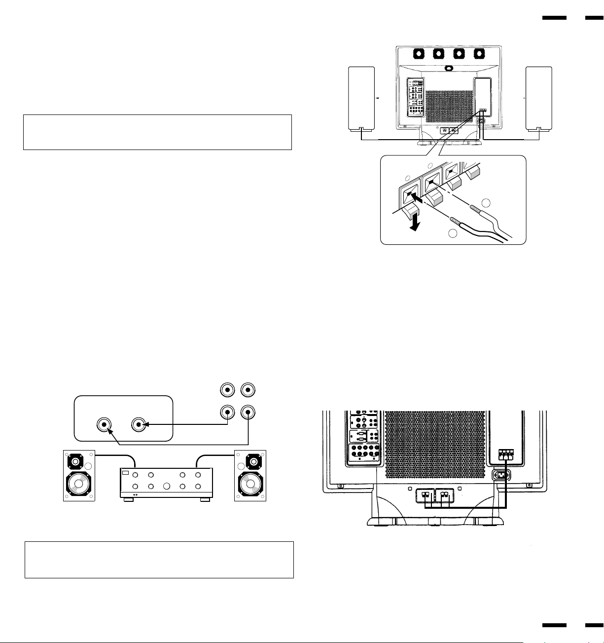
External Speaker Connections
External speakers may be connected to the monitor to reproduce sound from
VIDEO 1, VIDEO 2, RGB 1 or RGB 2 signal sources.
External speakers may be connected directly to the EXTERNAL SPEAKERS
terminals or indirectly by connecting a stereo system amplifier to the audio
outputs.
CAUTION: Unplug the monitor and all connected components before con-
necting external speakers. Use only speakers with 8-ohm impedance and a
power output rating of 5 watts or more.
To connect external speakers directly to the monitor:
1. Strip the ends of the speaker wires.
2. Press down a button below the EXTERNAL SPEAKERS terminals, insert
the speaker wire and release the button to secure a speaker wire connec-
tion:
[a] Connect the right speaker (located at right side of the monitor when
viewed from the front) positive (+) wire to RIGHT +.
[b] Connect the right speaker negative (-) wire to RIGHT -.
[c] Connect the left speaker negative (-) wire to LEFT -.
[d ]Connect the left speaker positive wire (+) to LEFT +.
SPEAKER SELECT
INT
EXT
RIGHT
{
|
{
|
4 ft.
120cm
4 ft.
120cm
LEFT
RIGHT
To connect the monitor to stereo system speakers:
1. Connect L AUDIO output to the stereo amplifier L AUX input.
2. Connect R AUDIO output to the stereo amplifier R AUX input.
IMPORTANT: Do not connect speakers to both the monitor EXTERNAL
SPEAKERS terminals and to the stereo amplifier. This could damage both
the monitor and the speakers.
28
27
HJJKKKASDFFF
BNGGDFDFGHY
ZZXXC
CCVDFVFF
ADFGRTRYT
ADFGRTRYT
SFGHHHJJ SFGHHHJJ
DFFGGGG
AFHUJTT
AFHUJTT
DFFGGGG
2Q 2Q
2Q
2Q
JGHDYSTEOYII DYASGHIROYUKIAIZAWA
THROUGH
OUT
IN
R
R
L
LINE OR
AUX INPUT
LINE OR
AUX INPUT
STEREO AMP
L (MONO)
VIDEO or RGB AUDIO L and R
outputs of PlasmaSync 3300
-
+
To enable the internal speakers, use the supplied speaker cables to con-
nect between the external speaker terminals and the internal speaker termi-
nals.

Controls/Adjustments
Power
1. Plug in the power cord to an electrical outlet to connect power.
2. Press POWER to turn the monitor on.
3. Press POWER again to turn the monitor off.
Press the POWER OFF key on the remote control unit to turn the monitor
off when the monitor is turned on.
The monitor will go into the standby condition and the STANDBY/POWER
indicator will light up orange.
Press the POWER ON key on the remote control unit to turn the monitor on
when the monitor is in the standby condition. The STANDBY/POWER indi-
cator will light up green.
Video Signal Input Settings
Video Input Selection
Press the desired input selection key (VIDEO 1 or VIDEO 2) on the remote
control unit or the monitor.
NOTE: During VIDEO input, set the 75Ω/HIGH switch to “75Ω” if VIDEO
THROUGH OUT is not being used.
Video Signal, Picture Adjustments
1)To adjust:
a. CONTRAST
Adjust the contrast of video display.
b. BRIGHT
Adjust the brightness of video display.
c. COLOR
Adjust the color intensity of video display.
d. TINT
Adjust red and green values of video display.
e. SHARPNESS
Adjust picture detail of video display.
2) Adjust the picture position.
To reset the stored adjustment data and recall the factory preset data:
Press the NORMAL keys.
29
30
RGB Signal Input Settings
RGB 1 Signal Input
Proceed as follows for correct setting of the monitor when input is via mini D-
SUB 15 Pin (ANALOG) terminal.
Connect IBM PC or Macintosh to the mini D-SUB 15 Pin terminal, and press
RGB 1.
RGB 2 Signal Input
When using with a .
1. Connect the R, G, B, H/CS and V terminals on the terminal board to the
outputs of your RGB equipment.
2. Set all of the 75Ω/HIGH Impedance select switches to “75Ω”.
3. Press the RGB 2 key.
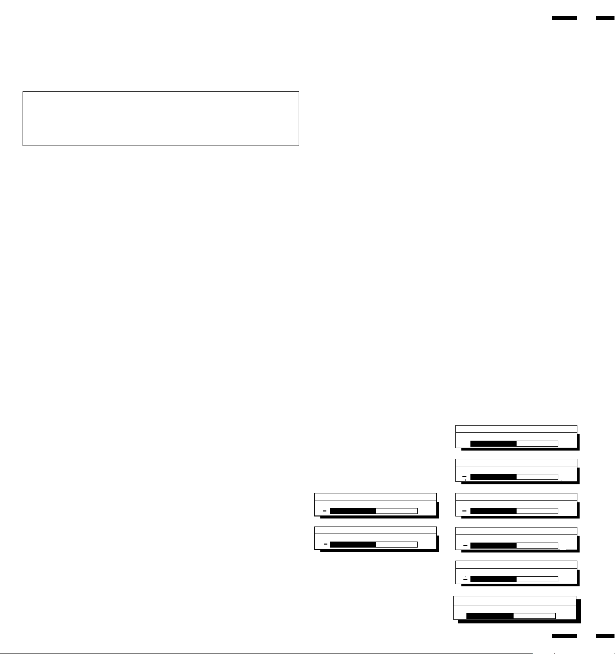
Size Control
{ |
Width
Size Control
{ |
Height
Position Control
{ |
Left/Right
Position Control
{ |
Down/Up
Side Pin Control
{ |
In/Out
Scan Select
Over Scan
Under Scan
Visual Control
Contrast
Visual Control
Color
Visual Control
Tint
Visual Control
Sharpness
Volume Control
MUTE: On
Visual Control
Brightness
Brightness
Contrast
Color
Tint
Sharpness
Volume
V-HEIGHT
H-POSITION
V-POSITION
Side Pin
Scan Select
H-WIDTH
{ |
{ |
{ |
{ |
{ |
{ |
Volume Control
1. Adjust the volume by pressing the VOLUME keys (Ä/ ).
2. To cancel sound, press the MUTE key on the remote control unit; press
again to restore sound.
RGB Signal, Picture Adjustments
1. a)Adjust the contrast of RGB display.
b)Adjust the brightness of RGB display.
2. Adjust the picture position.
See “Signal Identification Flowchart” on pages 43 and 44.
NOTE: To reset the stored adjustment data and recall the factory preset
data, press the NORMAL key on the remote control unit.
NOTE: Over adjusting the POSITION Up/Down may cause a picture to dis-
tort. If this happens, readjust the picture so that the distortion is not seen.
31
32
OSM
TM
Controls
NEC's new OSM, or On-Screen Manager, System offers the ultimate form of
monitor controls. Keys on the remote control unit allow you to easily navigate
through menus and adjust controls. As you chose controls, the moving icon
shows you what the chosen control will do. These pictures give you immediate
understanding of the controls.
OSM controls include extended controls such as Position, White Balance and
other OSM utilities. Adjustments are saved instantly. The currently addressed
control can be reset to factory settings by pressing the NORMAL key.
OSM keys on the remote control unit function as follows:
PROCEED : accesses the OSM controls.
-in the main menu: proceeds to the selected
menu choice.
-in a submenu: proceeds to the control in that
submenu.
EXIT : in the main menu: exits the OSM controls.
- in a submenu: exits to the OSM main menu.
POSITION CONTROL up/down : moves the arrow up or down to select one of
the controls.
POSITION CONTROL-/+ : in the main menu: has no function.
-in a submenu: moves the bar in the + or - direction
to increase or decrease the adjustment.
NORMAL (RASTER/VISUAL)
: resets the currently selected control to the factory
setting.
-in the main menu: resets all the controls within the
selected menu.
-in a submenu: resets the selected control.
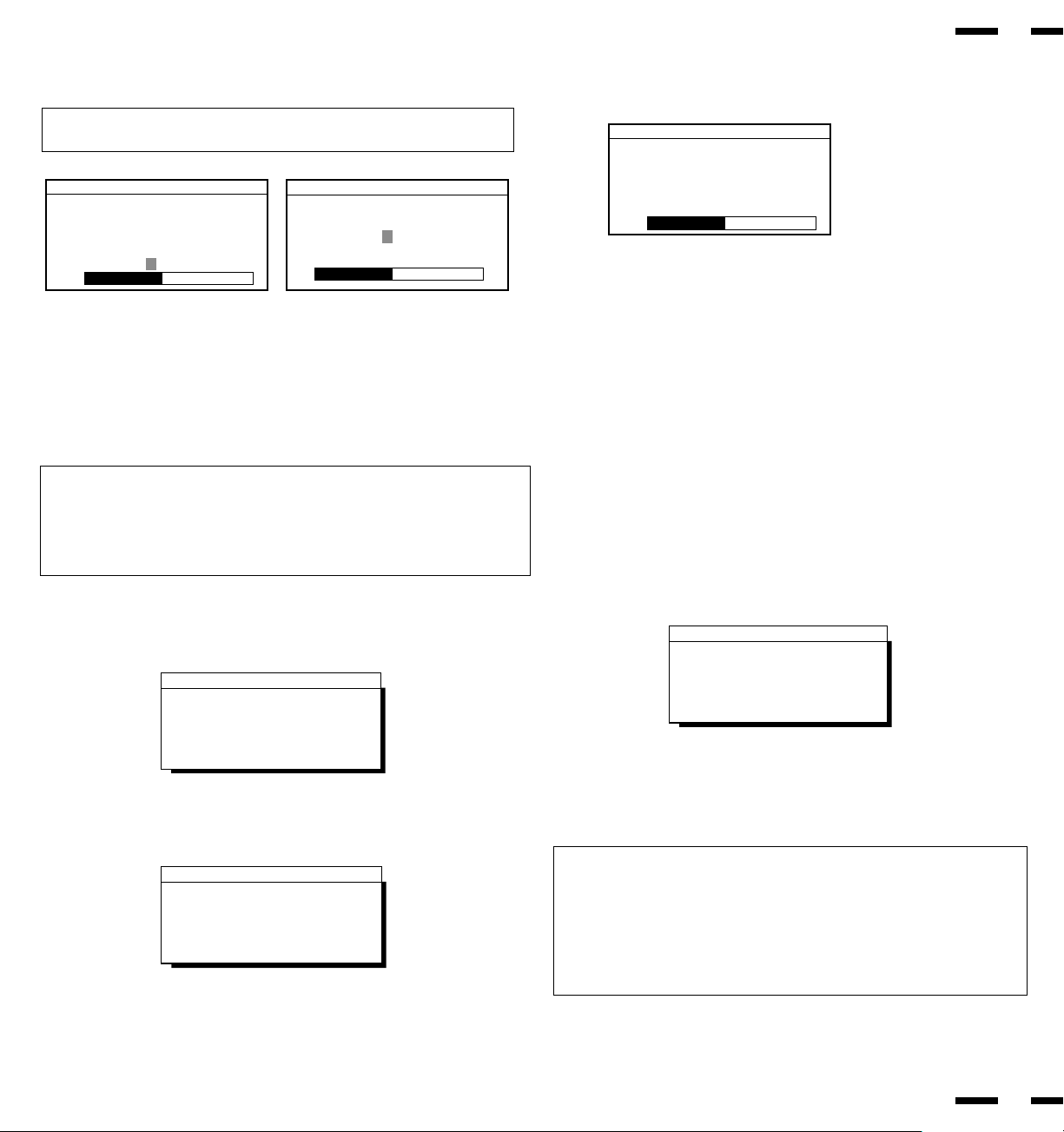
Typical OSM windows have the following elements:
arrow : indicates the selected menu or control.
moving icon : provides a quick moving illustration of what the
control will do (also indicates the direction of control
when adjusting).
scroll bar : indicates direction of adjustment.
Ä
Direct Control Screen
To switch to another control screen, press any one of the other keys.
*To end the OSM display, press EXIT.
*If no key operation is made within three seconds, the OSM display will disap-
pear.
Audio Control
Volume/Mute: On
+
-
Volume
+
+
+
+
+
+
+
Accessing OSM
Press the PROCEED key.
Turning off OSM
Press the EXIT key when in the main menu ; press the EXIT key twice when in
submenus.
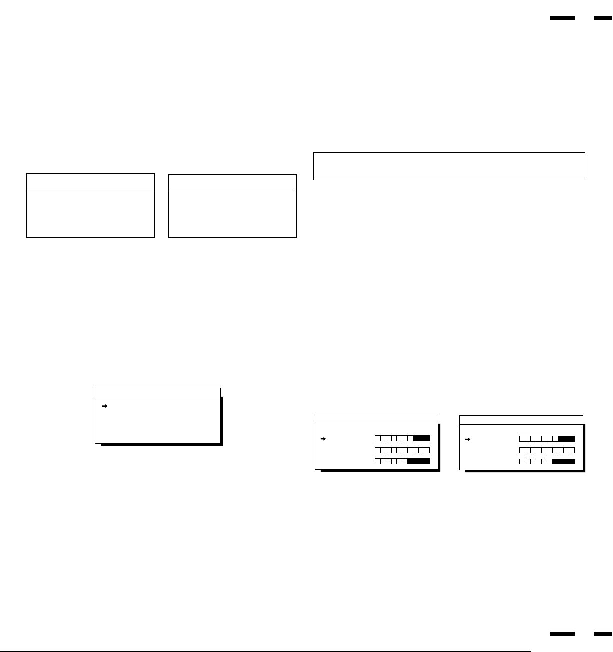
OSM Menus
Main Menu
On-Screen Manager' s main menu of Controls gives you an overview of the
selection of controls available.
The arrow in the bottom or upper right corner indicates further choices are
available. Use the Up or Down control keys to scroll through all of the options.
33
POSITION CONTROL +/- (Left/Right) : has no function.
POSITION CONTROL Up/Down : proceeds to the selected menu
choice.
EXIT : exits the OSM controls.
PROCEED : proceeds to the next control in the
submenu.
NORMAL : resets all the controls within the
selected menu.
NOTE: The NORMAL function is not needed in the OSM Turn Off Time,
Language Select menus, and Volume Control.
34
White Balance
Language
OSM Location
OSM Turn Off Time
OSM Gain
.... more
ON SCREEN MANAGER
MAIN MENU OF CONTROLS
➔
➔
Display Mode
Position
Auto Picture
Visual
Audio
ON SCREEN MANAGER
MAIN MENU OF CONTROLS
➔
➔
While in the main menu, the keys on the remote control unit work as follows:
White Balance Controls
The White Balance controls allow you to adjust the white balance.
POSITION CONTROL Up/Down : moves the arrow up or down to select
either Gain or Bias controls.
PROCEED : proceeds to the adjust menu.
EXIT : exits to the main menu.
NORMAL (VISUAL) : resets the current white balance controls
to the factory setting.
White Balance Controls
Gain Controls
Bias Controls
White Balance Controls
Bias:
Red
Green
Blue
White Balance Controls
Gain:
Red
Green
Blue
POSITION/CONTROL Up/Down :moves the arrow up or down to select one of
the choices.
POSITION/CONTROL +/- :moves the bar to increase or decrease the adjust-
ment.
EXIT :exits to the submenu.
NORMAL (VISUAL) :resets the current selected control to the fac-
tory setting.
Gain
Bias
35
36
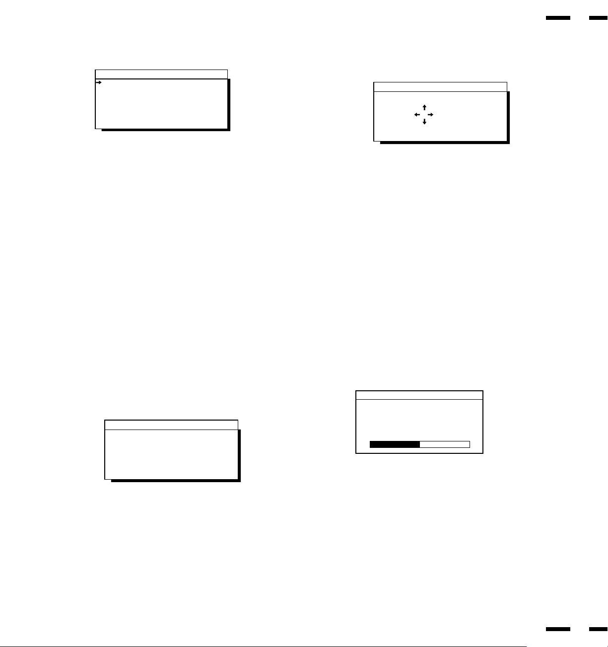
OSM Turn Off Time
The OSM menu will stay on as long as it is in use. In the OSM Turn Off Time
submenu, you can select how long the monitor waits after the last touch of a
key to shut off the OSM menu. The preset choices are 3, 5, 10, 30, and 60
seconds. Note that 30 seconds is the factory preset.
POSITION/CONTROL +/- : selects the preset time in increasing or decreasing
order.
EXIT : exits to the main menu.
OSM Location Control
You can choose where you would like OSM image to appear on your screen.
Selecting OSM location allows you to manually adjust the OSM menu left,
right, up, or down.
POSITION/CONTROL Up/Down : moves the OSM menu up or down.
POSITION/CONTROL +/- : moves the OSM menu right or left.
EXIT : exits to the main menu.
NORMAL (RASTER) : resets the current selected control to the
factory setting.
OSM Location Controls
Up
Down
Left
Right
OSM Turn Off Time
OSM Turn Off Time
Seconds:
35
10
30 60
Language Select
OSM Menus are available in six languages.
POSITION/CONTROL +/-: moves the arrow up or down to select one of the six
languages.
EXIT : exits to the main menu.
English
Deutsch
Français
Español
Italiano
Svenska
Language Select
OSM Gain Control
The OSM Gain allows you to manually adjust the brightness of OSM menu.
POSITION/CONTROL +/- : adjusts the brightness of the OSM menu. Press
+ for brighter OSM menu; - for dimmer OSM
menu.
EXIT : exits to the main menu.
NORMAL (RASTER) : resets the current selected control to the
factory setting.
OSM Gain
➔
OSM Gain
+
-
Position Controls
The Position controls allow you to adjust the position of the image.
38
37
Position Down/Up : moves the image vertically up or down.
Position Left/Right : moves the image horizontally left or right.
POSITION/CONTROL Up/Down : moves the arrow up or down to select one of
the choices.
POSITION/CONTROL +/- : moves the bar to increase or decrease the ad-
justment.
EXIT : exits to the main menu.
NORMAL (RASTER) : resets the current menu control to the factory
setting.
Auto Picture Control (Picture ADJ/Fine Picture)
The Auto picture control allows you to adjust the Picture Adjustment and Fine
Picture.
Position
Down/Up
Left/Right
Position
➔
+
-
Position
Down/Up
Left/Right
Position
➔
+
-
Auto Picture : Off
Picture ADJ
Fine Picture
Auto Picture
➔
+
-
•The Picture Adjustment control allows you to fine tune the computer image
or to remove vertical banding that might appear. This function adjusts the
clock frequencies that eliminate banding in the image.
•The Fine Adjustment adjusts the clock phase or reduces video noise, dot
interference or cross talk. (This is evident when parts of the image appear to
be shimmering.)
NOTE:
•The Picture ADJ and Fine Picture features are available only when
the Auto Picture is off. The Picture ADJ and Fine Picture features are
not available for Video or S-Video source.
•When the Auto Picture is on, the Picture ADJ and Fine Picture
adjustments are made automatically.
POSITION/CONTROL Up/Down : moves the arrow up or down to select one of
the choices.
POSITION/CONTROL +/- : moves the bar to increase or decrease the ad-
justment.
EXIT : exits to the main menu.
NORMAL (RASTER) : resets the current menu control to the factory
setting.
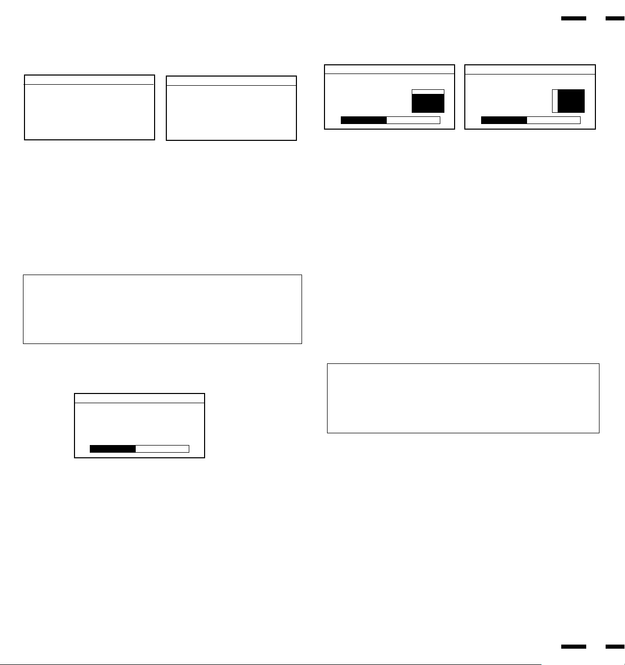
Display Mode
Display Mode provides you information about the current resolution display
and technical data including the horizontal and vertical frequency.
Mode : indicates the resolution of the current input signal (dot x line).
H. Freq : indicates the horizontal frequency of the current input signal.
V. Freq : indicates the vertical frequency of the current input signal.
H. Pol:indicates the polarity of the horizontal sync. signal.
V. Pol : indicates the polarity of the vertical sync. signal.
Neg : indicates the polarity is negative.
Pos : indicates the polarity is positive.
Source : indicates the current input source.
Memory : indicates the memory area.
EXIT : exits to the main menu.
NOTE: Vertical frequencies identified by the OSM System's Display Mode
function may exhibit variances from the actual vertical frequency of the
connected input source. Vertical frequencies between 60-70 Hz may vary by
+/- 3 Hz; vertical frequencies from 70 Hz to 100 Hz may vary by +/-5 Hz. In
these situations, it is recommended that the vertical frequency identified by
the OSM System Display Mode function be regarded as an approximate
reference within tolerances stated above.
RGB
VIDEO
Display Mode
Mode : 640 x 480
H Freq. : 31.47 kHz
V Freq. : 60 Hz
H Pol. : Neg
V Pol. : Neg
Source : RGB 1
Memory : Factory
Display Mode
Mode :NTSC
Source : Video 1
40
39
NORMAL
Pressing NORMAL allows you to reset the settings back to the factory settings.
The above warning statement will appear to confirm that you do want to reset
all raster settings.
The above warning statement will appear to confirm that you do want to reset
all visual settings.
WARNING
ABOUT TO RESET
Raster
Press:
NORMAL-Reset
EXIT-Cancel
WARNING
ABOUT TO RESET
Visual
Press:
NORMAL-Reset
EXIT-Cancel
WARNING
ABOUT TO RESET
XXXXX
Press:
NORMAL-Reset
EXIT-Cancel
Screen when NORMAL is pressed during adjustment.
The above warning statement will appear to confirm that you do want to reset
individual settings. XXXXX refers to a specific adjustment item you wish to
reset.
NOTE:
• In addition to OSM controls, adjustments can be directly accessed with the
remote control keys. When adjusting with the remote control keys, the on-
screen display for the related adjustment appears instead of the OSM
menu.
• When Pin No. 5 of the DIP SW 1 is set at the OFF position, OSM controls
are not available while the remote control direct access is possible.
Screen when RASTER NORMAL is pressed with no OSM display.
Screen when VISUAL NORMAL is pressed with no OSM display.
Volume Control
The Volume control allows you to adjust the volume and balance, or to mute
the sound.
POSITION/CONTROL Up/Down :moves the arrow up or down to select one of
thechoices.
POSITION/CONTROL +/- :moves the bar in the + or - direction to
increase or decrease the volume; + to increase
the righ speaker volume and - for the left
speaker volume.
EXIT :exits to the main menu.
Visual Controls
The Visual controls allow you to adjust the picture controls such as brightness,
contrast, color, tint, sharpness and gamma.
NOTE: The color, tint, and sharpness controls are not available in the RGB
mode and the tint not available in the PAL and SECAM mode.
POSITION/CONTROL Up/Down : moves the arrow up or down to select one of
the choices.
POSITION/CONTROL +/- : moves the bar to increase or decrease the
picture adjustment.
EXIT : exits to the main menu.
NORMAL (VISUAL) : resets the current selected control to the
factory setting.
Brightness
Contrast
Color
Tint
Sharpenss
Gamma : 1 2 3 4 5 6 7
RGB
VIDEO
Visual Controls
➔
+
-
Visual Controls
➔
+
-
Brightness
Contrast
Gamma : 1 2 3 4 5 6 7
NOTE:
• "Gamma" adjusts the brightness of a dark area on the screen. You can
adjust seven levels, in decreasing order of darkness.
• When "Gamma" is selected, the bar graph, plus and minus symbol do not
appear.
Volume
Balance
Mute: Off
Audio Controls
➔
+
-
NOTE: “GND” means to connect with pin 9.
NOTE: If EXT. Control is set to ON, the exter control will be effective only for
the above functions. If EXT. Control is set to OFF, PC CTL will be effective.
External Control Function
External Control Port Pin Assignments
Pin No.
1-3
4, 5
6-8
9
10
11-14
15
NO.5
OPEN
OPEN
GND
GND
NO.4
OPEN
GND
OPEN
GND
INPUT
VIDEO 1
VIDEO 2
RGB 1
RGB 2
OPEN
-
-
-
OFF
-
-
GND
-
-
-
ON
-
-
Signal to be connected
Not Used
INPUT SELECT
Not Used
GND
Power ON/OFF Selection
Not Used
GND
42
41
1
2
34
5
11
12
13
1415
6
7
8
9
10

44
43
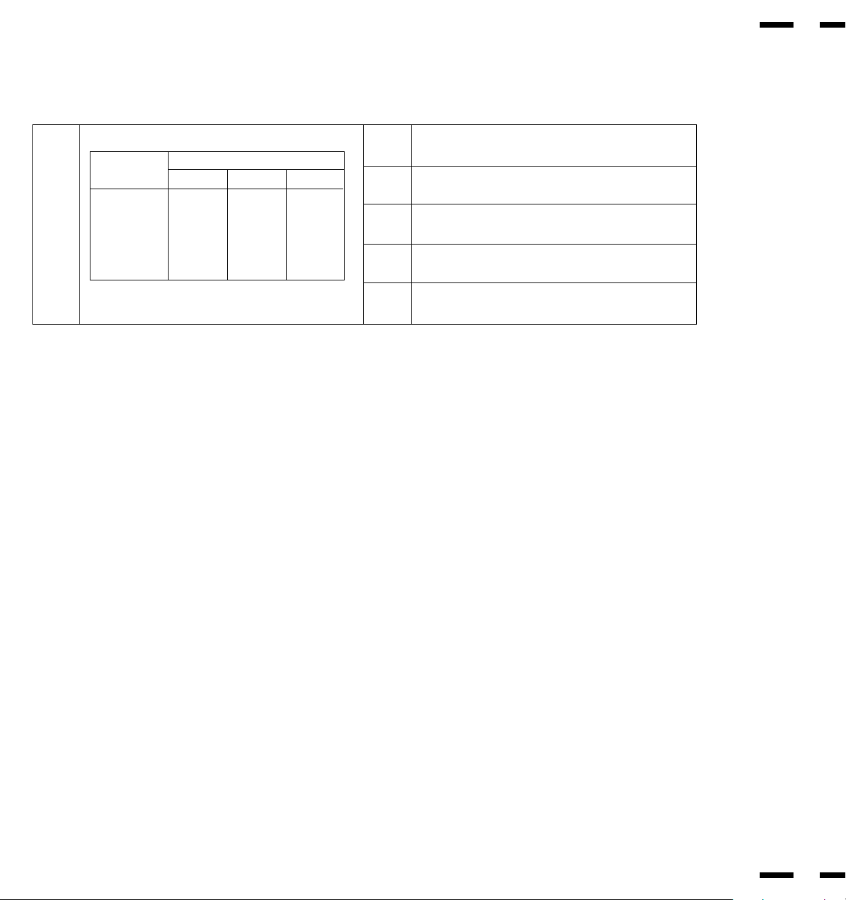
Signal Identification Flowchart
Input signal
28 kHz<fH<34 kHz fV<65 Hz 640 x 480@60 Hz (VESA, VGA)
38.6 kHz<fH<42 kHz 640 x 480@75 Hz (XGA-2)
65 Hz<fV 640 x 400@70 Hz (IBM)
65 Hz<fV 640 x 480@67 Hz (Macintosh)
65 Hz<fV<74Hz 640 x [email protected] Hz (VESA)
74 Hz<fV 640 x 480@75 Hz (VESA)
NOTE: There are other two memory locations for NTSC and PAL than the above.
User preset : 9
Factory preset : 11
Total : 20

Troubleshooting
45
46
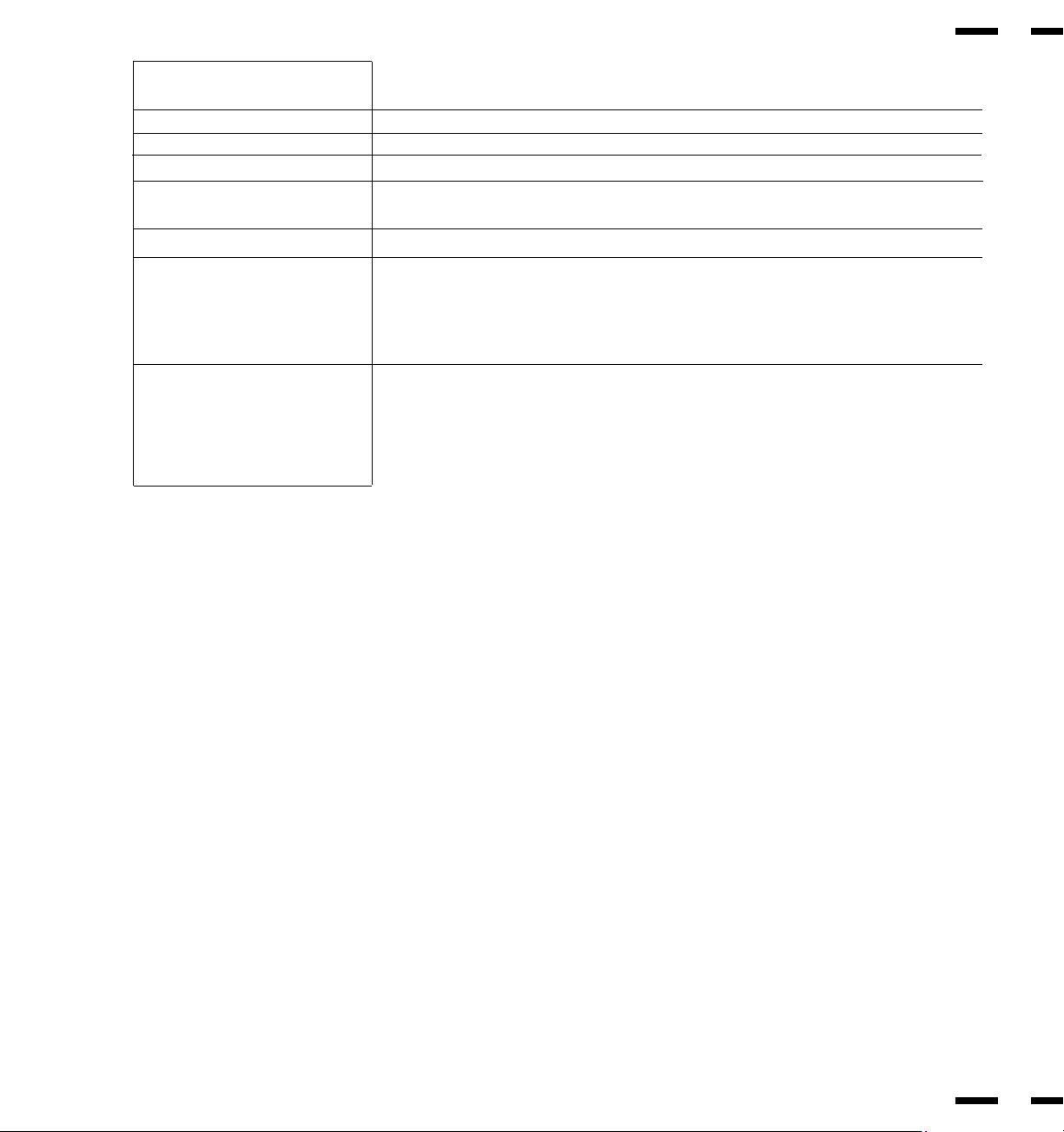
Before arranging for service by the NEC Service Center, check the following to be sure repairs are needed.
Problem
No Picture or Sound
Sound OK; poor picture
with VIDEO signal input.
Sound OK; poor picture with
RGB signal input.
Picture OK; poor or no sound.
Poor sound from external speakers
or setereo system speakers
Remote control does not work.
STANDBY/POWER indicator is
blinking
Correction
Plug in power cord.
Be sure wall switch is on and outlet has power.
Switch to ON or connect to an active AC outlet.
Correct all connections.
Press correct RGB1, RGB 2, VIDEO 1 or VIDEO 2 button.
Adjust picture controls as needed.
Try another location for the monitor.
Be sure all connections are secure.
Check 75 ohm high impedance select switch.
Adjust picture controls as needed.
Check pin assignments and connections.
Be sure all connections are secure.
Adjust volume.
Correct audio connections.
Adjust volume controls.
Press again to restore sound.
Secure all cable connections.
Check volume controls of all components.
Install new batteries.
Point remote control directly at Sensor Window.
Use the remote control unit within 30° left and right
of center (at a distance of within 22ft).
Set Pin no. 8 to ON.
Set Pin no. 7 of DIP SW 1 to OFF.
Unplug the remote cable from the monitor.
Check the input signal.
Possible Cause
Power cord unplugged.
Power outlet inactive.
Power of external equipment is not ON.
External equipment has been incorrectly connected.
Incorrect input selection.
Improper control setting.
Local interference.
Cable interconnections.
Input impedance is not correct level.
Improper control setting.
Incorrect 15 PIN connector pin connections.
Cable interconnections.
Volume is not adjusted.
Poor audio connections from external source.
Improper control settings.
MUTE key is ON.
Cable interconnections.
Improper volume setting.
Weak batteries.
Obstacle between Remote Control and Sensor
Window. (Wireless)
You are not within the effective operating range.
(Wireless)
Incorrect setting of DIP SW 1. (Wireless)
When in the EXT. CONTROL mode, the remote
control unit will not operate the monitor.
The remote cable is plugged into the REMOTE IN termi-
nal. (Wireless)
Horizontal and/or vertical sync signal is not present
when the Intelligent Power Manager control is on.
In the following case, power off the monitor immediately and contact your dealer or authorized NEC Service Center.
The monitor turns off in 5 seconds after powering on and then the STANDBY/POWER indicator blinks. It indicates that the power supply circuit or, one
or more fans have been damaged.

Specifications
Plasma Screen 33 inch Visual size (Diagonal), AC Drive type
Phosphor stripe trios Ph 1.05 mm, Pv 1.05 mm
Medium-short persistence phosphor
Optical filter coating
Aspect ratio: 3 : 4
Display color: 260,000 colors (RGB 64 shades of gray respectively)
RGB Input Terminals RGB: D-SUB 15pin BNC (R, G, B, H and V)
: Video : Analog 0.7Vp-p/75 Ohms (Positive)
: Sync. : Separate Sync. TTL level, 0.7 - 4.0Vp-p/75 Ohms..........BNC only
Horizontal Sync. (Positive/Negative)
Vertical Sync. (Positive/Negative)
: Composite Sync. TTL Level (Positive/Negative)
: Composite Sync. On Green Video 0.3Vp-p (Negative)
RGB Output Terminals D-SUB 15pin BNC (R, G, B, H, V)
THROUGH OUT
Video Input Terminals
VIDEO 1.0Vp-p, 75 Ohms unbalanced (BNC-Jack), Composite video signal, Sync-negative.
S-VIDEO Y : 1.0Vp-p, 75 Ohms unbalanced, Sync-negative.
C : 0.28Vp-p, 75 Ohms unbalanced, Color burst level.
Video Output Terminals
THROUGH OUT 1.0Vp-p, 75 Ohms unbalanced (BNC Jack), Composite video signal, Sync-negative.
THROUGH OUT (S-VIDEO 1, 2) Y : 1.0Vp-p, 75 Ohms unbalanced, Sync-negative.
C : 0.28Vp-p, 75 Ohms unbalanced, Color burst level.
Audio Input Terminals Left (Mono) : 0.5 Vrms, high impedance (Pin-Jack)
VIDEO 1, 2 / RGB Right : 0.5Vrms, high impedance (Pin-Jack)
Audio Output Terminals Left : 0.5 } 0.1 Vrms, less than 22 K Ohms (Pin-Jack)
THROUGH OUT Right : 0.5 } 0.1 Vrms, less than 22 K Ohms (Pin-Jack)
External Control mini D-SUB 15pin (IN/THROUGH OUT)
(IN/THROUGH OUT)
SOUND Output
Internal 2.5W+2.5W (THD 10%) at 16 Ohm
External 5W+5W (THD10%) at 8 Ohm
Speaker Oval type 9 X 5.5 cm
16 Ohm, 2pcs.
Display Colors Analog Input: Unlimited colors
Synchronization Range Horizontal: 15.5 kHz to 39.5 kHz (Automatically)
Vertical:46 Hz to 76 Hz (Automatically)
48
47
Maximum Resolution RGB: 640(H) x 480(V) pixels
VIDEO: 400 horizontal lines
Signal Bandwidth 33 MHz (maximum)
Current Rating AC 120 V, 60 Hz
Power Consumption 4.5 A (maximum)
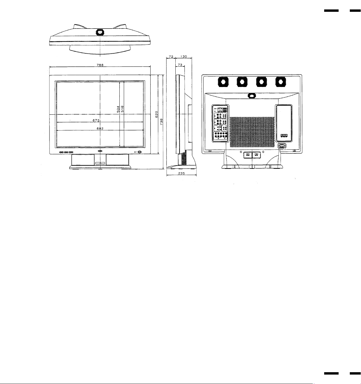
Dimensions 31.1(W) x 29.1(H) x5.2 (D) inches/ 788(W) x 738(H) x130(D) mm
(Height: 24.5 inches/ 620 mm; not including the base)
Weight 73.63 lbs/33.4 kg (60.85 lbs/27.6 kg not including the base)
Environmental Considerations Operating Temperature : 0 to 40
Humidity : 0 to 90%
Altitude : 0 to 10,000 feet
Storage Temperature : -10 to 50
Humidity : 0 to 95%
Altitude : 0 to 45,000 feet
Regulations : UL Approved (UL 1950, CSA 950)
DOC Canada requirements
Meets FCC class A requirements
All specifications are subject to change without notice.
50
49
51
52
Dimensions

HOW YOU CAN GET WARRANTY SERVICE
To obtain service on your product, consult the dealer from whom you pur-
chased the product, or ship it prepaid to any authorized NECTECH service cen-
ter.
Whenever warranty service is required, the original dated invoice (or a copy)
must be presented as proof of warranty coverage, and should be included in
any shipment of the product. Please also include in any mailing, your name,
address and a description of the problem(s).
For the name of the nearest NECTECH authorized service center, call NECTECH
at 800-836-0655.
LIMITATION OF IMPLIED WARRANTIES
All implied warranties, including warranties of merchantability and fitness for a
particular purpose, are limited in duration to the length of this warranty.
EXCLUSION OF DAMAGES
NECTECH's liability for any defective product is limited to the repair or replace-
ment of the product at our option. NECTECH shall not be liable for:
Damage to other property caused by any defects in this product, damages
based upon inconvenience, loss of use of the product, loss of time, commercial
loss; or
Any other damages whether incidental, consequential or otherwise. Some
states do not allow limitation on how long an implied warranty lasts and/or do
not allow the exclusion or limitation of incidental or consequential damages, so
the above limitations and exclusions may not apply to you.
HOW STATE LAW RELATES TO THE WARRANTY
This warranty gives you specific legal rights, and you may also have other rights
which vary from state to state.
Damage, deterioration or malfunction resulting from:
Accident, misuse, abuse, neglect, fire, water, lightning or other acts of na-
ture, unauthorized product modification, or failure to follow instructions sup-
plied with the product.
Repair or attempted repair by anyone not authorized by NECTECH.
Any shipment of the product (claims must be presented to the carrier).
Removal or installation of the product.
Any other cause which does not relate to a product defect.
Burns or residual images upon the phosphor of the tubes.
Cartons, carrying cases, batteries, external cabinets, magnetic tapes, or any
accessories used in connection with the product.
WHAT WE WILL PAY FOR AND WHAT WE WILL NOT PAY FOR
We will pay labor and material expenses for covered items, but we will not pay for
the following:
Removal or installation charges.
Costs of initial technical adjustments (set-up), including adjustment of user con-
trols. These costs are the responsibility of the NECTECH dealer from whom the
product was purchased.
Payment of shipping charges.
NEC Technologies, Inc.(hereafter NECTECH)warrants this product to be free from
defects in material and workmanship under the following terms.
HOW LONG IS THE WARRANTY
Parts and labor are warranted for (1) One Year and Plasma display for (1) One
year from the date of the first customer purchase.
WHO IS PROTECTED
This warranty may be enforced only by the first purchaser.
WHAT IS COVERED AND WHAT IS NOT COVERED
Except as specified below, this warranty covers all defects in material or work-
manship in this product. The following are not covered by the warranty:
Any product which is not distributed in the U.S.A. Canada, and Mexico by
NECTECH or which is not purchased in the U.S.A. Canada, and Mexico from an
authorized NECTECH dealer.
If you are uncertain as to whether a dealer is authorized, please contact
NECTECH at 800-836-0655. If you are uncertain as to whether a dealer is autho-
rized, please contact NECTECH .
Any product on which the serial number has been defaced, modified or re-
moved.
MULTIMEDIA MONITORS
Limited Warranty
1.
3.
4.
a.
b.
c.
d.
e.
f.
1.
2.
3.
1.
2.
3.
1.
2.
PROFESSIONAL GRAPHICS PRODUCTS
53
2.
FOR MORE INFORMATION, TELEPHONE 800-366-5213
NEC TECHNOLOGIES, INC.
1250 N. Arlington Heights Road, Suite 500
Itasca. Illinois 60143-1248
NOTE: All products returned to NECTECH for service MUST have prior approval. To get
approval, call NEC Technologies at 800-836-0655.
54