
INSTRUCTION MANUAL
GAS POWERED CHIPPER SHREDDER
Model #PS1130
Have product questions or need technical support? Please feel free to contact us!
Website: www.Amerisuninc.com
www.powersmartusa.com
Toll free: 1-800-791-9458 M-F 9-5 EST
Email: [email protected]


3
CONTENTS
Technical data…...………………………………………………………... 3
Introduction………………………………………………………………. 4
Safety information…….………………………………………………... 4
General safety procedures ……....……………………………………… 5
Important safety instructions……………………………………………. 6
Symbols…………………………………….…….…….…….………..…. 9
Knowing your chipper shredder……………………….………………… 10
Assembly instruction………………………………………………...….. 12
Operation……………………....………………………………………… 14
Maintenance……………………………………………………………... 19
Transport&Storage……………………………………………………… 22
Troubleshooting…………………………………………………………. 23
Exploded view & parts list……………………………………………… 26
Warranty………………………………………………………………… 32
TECHNICAL DATA
Gas powered chipper shredder Model # PS1130
Engine type: 4 Stroke, OHV, single cylinder with forced air-cooling system
Spark plug gap: 0.027" - 0.031"(0.7-0.8 mm )
Displacement: 212cc
Fuel type: 87+ octane stabilizer-treated unleaded gasoline
Fuel tank capacity: 0.95 Gallon
Engine oil type: 10W-30
Oil capacity: 16.9 fl.oz
Horsepower: 7.0hp
Start type: Recoil
Cutting capacity: 3 inch
Hopper dimension: 17.7 x 13.9 inches
Wheel: 12 inch
Package dimensions (L x W x H): 33.5 x 23.8 x 23.8 inches
Weight: 132 lb.

4
INTRODUCTION
Thank You for Purchasing a PowerSmart® Product. This manual provides information regarding the
safe operation and maintenance of this product. Every effort has been made to ensure the accuracy of
the information in this manual. PowerSmart® reserves the right to change this product and
specifications at any time without prior notice.
Please keep this manual available to all users during the entire life of the chipper shredder.
This manual contains special messages to bring attention to potential safety concerns,
chipper shredder damage as well as helpful operating and servicing information. Please
read all the information carefully to avoid injury and machine damage.
QUESTIONS? PROBLEMS?
Please contact our Customer Service Dept. with any questions and/or comments, either by Email:
[email protected], or Toll Free at (800) 791-9458. We are available Mon-Fri 9am-5pm EST
to help solve any issues that you might encounter.
NOTICE REGARDING EMISSIONS
Engines that are certified to comply with U.S. EPA emission regulations for SORE (Small Off Road
Equipment), are certified to operate on regular unleaded gasoline, and may include the following
emission control systems: (EM) Engine Modifications and (TWC) Three-Way Catalyst (if so
equipped).
SAFETY INFORMATION
Before operating this chipper shredder, read and observe all warnings, cautions, and instructions on
the chipper shredder and in this Owner’s Manual.
NOTE: The following safety information is not meant to cover all possible conditions and situations
that may occur. Read the entire Owner’s Manual for safety and operating instructions. Failure to
follow instructions and safety information could result in serious injury or death.
This safety alert symbol is used to identify safety information about hazards that can result in personal
injury.
A signal word (DANGER, WARNING, or CAUTION) is used with the alert symbol to
indicate the likelihood and the potential severity of injury. In addition, a hazard symbol
may be used to represent the type of hazard.
DANGER indicates a hazard, which, if not avoided, will result in death or serious injury.
WARNING indicates a hazard, which, if not avoided, could result in death or serious injury.
CAUTION indicates a hazard, which, if not avoided, might result in minor or moderate injury.
CAUTION when used without the alert symbol, indicates a situation that could result in damage to
the engine.

5
GENERAL SAFETY PROCEDURES
For any questions regarding the hazard and safety notices listed in this manual or on the product,
please call (800) 791-9458 Mon-Fri 9-5 EST before using the engine.
DANGER: CARBON MONOXIDE
Using an engine indoors CAN KILL YOU IN MINUTES. Engine exhaust contains carbon
monoxide (CO). This is a poison gas you cannot see or smell. If you can smell the engine exhaust, you
are breathing CO. But even if you cannot smell the exhaust, you could be breathing CO.
NEVER use an engine inside homes, garages, crawlspaces, or other partly enclosed areas. Deadly
levels of carbon monoxide can build up in these areas. Using a fan, or opening windows and/or doors
will NOT properly vent CO nor supply adequate fresh air. ONLY use an engine outside and far away
from windows, doors, and vents. These openings can pull in engine exhaust.
Even if you use an engine correctly, CO may leak into the home. ALWAYS use a battery-powered or
battery-backup CO alarm in the home. If you start to feel sick, dizzy, or weak after the engine has been
running, move to fresh air RIGHT AWAY. See a doctor. You may have carbon monoxide poisoning.
WARNING: The exhaust from this product contains chemicals known to the State of California to
cause cancer, birth defects, or other reproductive harm.
WARNING: This engine may emit highly flammable and explosive gasoline vapors, which can
cause severe burns or even death if ignited. A nearby open flame can lead to explosion even if it isn’t
directly in contact with gasoline.
• Do not operate near an open flame.
• Do not smoke near the engine.
• Always operate on a firm, level surface.
• Always turn engine off before refueling. Allow engine to cool for at least 2 minutes before
removing fuel cap. Loosen cap slowly to relieve pressure in tank.
• Do not overfill fuel tank. Gasoline may expand during operation. Do not fill to the top of the
tank. Allow for expansion.
• Always check for spilled fuel before operating.
• Empty fuel tank and carburetor bowl before storing or transporting the engine.
WARNING: This engine produces heat when running. Temperatures near exhaust can exceed 1500F
(650 C).
Do not touch hot surfaces. Pay attention to warning labels on the engine identifying hot parts of the
machine.
Allow engine to cool down after use before touching engine or areas of the engine that become hot
during use.
CAUTION: Misuse of this engine can damage it or shorten its life.
Only use engine for its intended purposes.

6
IMPORTANT SAFETY INSTRUCTIONS
This machine is capable of amputating hands and feet and throwing objects. Failure to observe the
following safety instructions could result in serious injury or death.
Set up precautions
Gasoline fuel and fumes are flammable, and potentially explosive. Use proper fuel storage and
handling procedures. Do not store fuel or other flammable materials nearby.
Have multiple ABC class fire extinguishers nearby.
Operation of this equipment may create sparks that can start fires around dry vegetation. A spark
arrestor may be required. The operator should contact local fire agencies for laws or regulations
relating to fire prevention requirements.
Set up and use only on a flat, level, well-ventilated surface.
Wear ANSI-approved safety goggles, heavy-duty work gloves, and dust mask/respirator during
set up.
Use only lubricants and fuel recommended in the Specifications chart of this manual.
Operating precautions
Keep children away from the equipment, especially while it is operating.
Locate the Chipper/Shredder on a flat, level, sturdy surface capable of supporting the weight of
the Chipper/Shredder and any additional tools and equipment.
Be extremely cautious of the rotating Blades in the Chipper/Shredder. Never allow your hands,
fingers, or any other part of your body to enter the Chipper Chute or Hopper.
Never place your hands, fingers, feet, or any other part of your body close to the Discharge
Opening while the Chipper/Shredder is in operation.
Do not look into the Hopper, Chipper Chute or Discharge Opening when the machine is running.
Do not allow metal, stone, glass, or other foreign objects to be fed into the Chipper/Shredder. Use
a stick to push the tree limbs, leaves, etc. into the feed Hopper.
Do not allow Discharge Bag to overfill with processed material. This may prevent proper
discharge and can result in kickback of material through the feed Hopper.
If the machine becomes clogged, immediately turn the Engine off. Wait until the
Chipper/Shredder comes to a complete stop. Unplug the Spark Plug Wire from the Spark Plug.
Then clear the machine of the clogged material.
Keep all spectators at least six feet from the Engine during operation.
Fire Hazard! Do not fill fuel tank while engine is running. Do not operate if gasoline has been
spilled. Clean spilled gasoline before starting engine. Do not operate near pilot light or open
flame.
Do not touch engine during use. Let engine cool down after use.
Never store fuel or other flammable materials near the engine.
Only use a suitable means of transport and lifting devices with sufficient weight bearing capacity
when transporting the equipment.
Secure the equipment on transport vehicles to prevent it from rolling, slipping, and tilting.
Industrial applications must follow OSHA requirements.
Do not leave the equipment unattended when it is running. Turn off the equipment (and remove
safety keys, if available) before leaving the work area.
The equipment can produce high noise levels. Prolonged exposure to noise levels above 85 dBA
is hazardous to hearing. Wear ear protection when operating the equipment or when working
nearby while it is operating.
Wear ANSI-approved safety glasses and hearing protection during use.

7
People with pacemakers should consult their physician(s) before use. Electromagnetic fields in
close proximity to a heart pacemaker could cause pacemaker interference or pacemaker failure.
Caution is necessary when near the engine’s magneto or recoil starter.
Use only accessories that are recommended by POWERSMART for your model. Accessories
that may be suitable for one piece of equipment may become hazardous when used on another
piece of equipment.
Do not operate in explosive atmospheres, such as in the presence of flammable liquids, gases, or
dust. Gasoline-powered engines may ignite the dust or fumes.
Stay alert, watch what you are doing and use common sense when operating this piece of
equipment. Do not use while tired or under the influence of drugs, alcohol or medication.
Do not overreach. Keep proper footing and balance at all times. This enables better control of the
equipment in unexpected situations.
Use this equipment with both hands only. Using equipment with only one hand can easily result
in loss of control.
Dress properly. Do not wear loose clothing or jewelry. Keep hair, clothing and gloves away from
moving parts. Loose clothes, jewelry or long hair can be caught in moving parts.
Parts, especially exhaust system components, get very hot during use. Stay clear of hot parts.
Do not cover the equipment during operation.
Keep the equipment, engine, and surrounding area clean at all times.
Do not smoke, or allow sparks, flames, or other sources of ignition around the equipment,
especially when refuelling.
Use the equipment, accessories, etc., in accordance with these instructions and in the manner
intended for the particular type of equipment, taking into account the working conditions and the
work to be performed. Use of the equipment for operations different from those intended could
result in a hazardous situation.
Do not operate the equipment with known leaks in the engine’s fuel system.
When spills of fuel or oil occur, they must be cleaned up immediately. Dispose of fluids and
cleaning materials as per any local, state, or federal codes and regulations. Store oil rags in a
bottom-ventilated, covered, metal container.
Keep hands and feet away from moving parts. Do not reach over or across equipment while
operating.
Before use, check for misalignment or binding of moving parts, breakage of parts, and any other
condition that may affect the equipment’s operation. If damaged, have the equipment serviced
before using. Many accidents are caused by poorly maintained equipment.
Use the correct equipment for the application. Do not modify the equipment and do not use the
equipment for a purpose for which it is not intended.
Service precautions
Before service, maintenance, or cleaning:
a. Turn the engine switch to its “OFF” position.
b. Allow the engine to completely cool.
c. Then, remove the spark plug cap from the spark plug.
Keep all safety guards in place and in proper working order. Safety guards include muffler, air
filter, mechanical guards, and heat shields, among other guards.
Do not alter or adjust any part of the equipment or its engine that is sealed by the manufacturer or
distributor. Only a qualified service technician may adjust parts that may increase or decrease
governed engine speed.
Wear ANSI-approved safety goggles, heavy-duty work gloves, and dust mask/respirator during
service.
Maintain labels and nameplates on the equipment. These carry important information. If
unreadable or missing, contact POWERSMART for a replacement.
8
Have the equipment serviced by a qualified repair person using only identical replacement parts.
This will ensure that the safety of the equipment is maintained. Do not attempt any service or
maintenance procedures not explained in this manual or any procedures that you are uncertain
about your ability to perform safely or correctly.
Store equipment out of the reach of children.
Follow scheduled engine and equipment maintenance.
Refueling:
Do not refill the fuel tank while the engine is running or hot.
Do not smoke, or allow sparks, flames, or other sources of ignition around the equipment,
especially when refuelling.
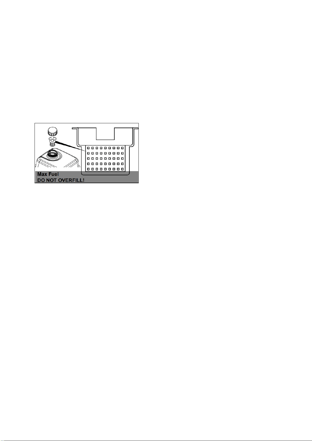
Do not fill fuel tank to the top. Leave a little room for the fuel to expand as needed.
TO PREVENT FUEL LEAKAGE AND FIRE HAZARD, do not fill fuel above the bottom of
fuel strainer.
Refuel in a well-ventilated area only.
Wipe up any spilled fuel and allow excess to evaporate before starting engine. To prevent FIRE,
do not start the engine while the smell of fuel hangs in the air.
Fig.1
9
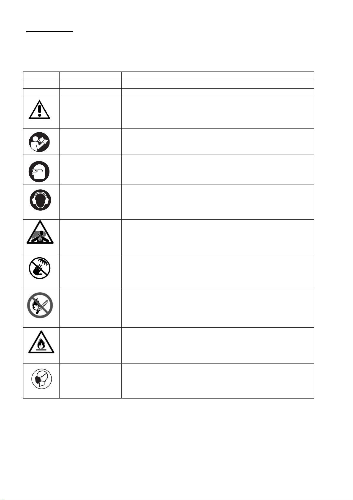
SYMBOLS
Some of the following symbols may be used on this product. Please study them and learn their
meaning. Proper interpretation of these symbols will allow you to operate the product better and safer.
SYMBOL
NAME DESIGNATION/EXPLANATION
Hp Horsepower
MIN Minutes Time
Safety Alert Precautions that involve your safety.
Read the user’s
manual
To reduce the risk of injury, user must read and understand user’s
manual before using this product.
Eye protection Wear eye protection when operating this equipment.
Hearing protection Use proper hearing protection when operating this equipment.
Risk of Respiratory
Injury
Operate engine OUTSIDE and far away from windows, doors,
and vents.
No Hands Symbol Failure to keep your hands away from the blade will result in
serious personal injury.
Risk of Fire while
handling fuel
Do not smoke while handling fuel.
Risk of Fire Do not refuel while operating. Keep flammable objects away from
engine.
Respiratory
protection
Use proper respiratory protection when operating this equipment.
10
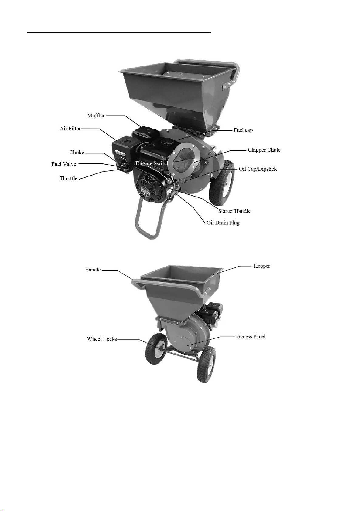
KNOWING YOUR CHIPPER SHREDDER
Handle
Wheel Locks
Fig.2
11
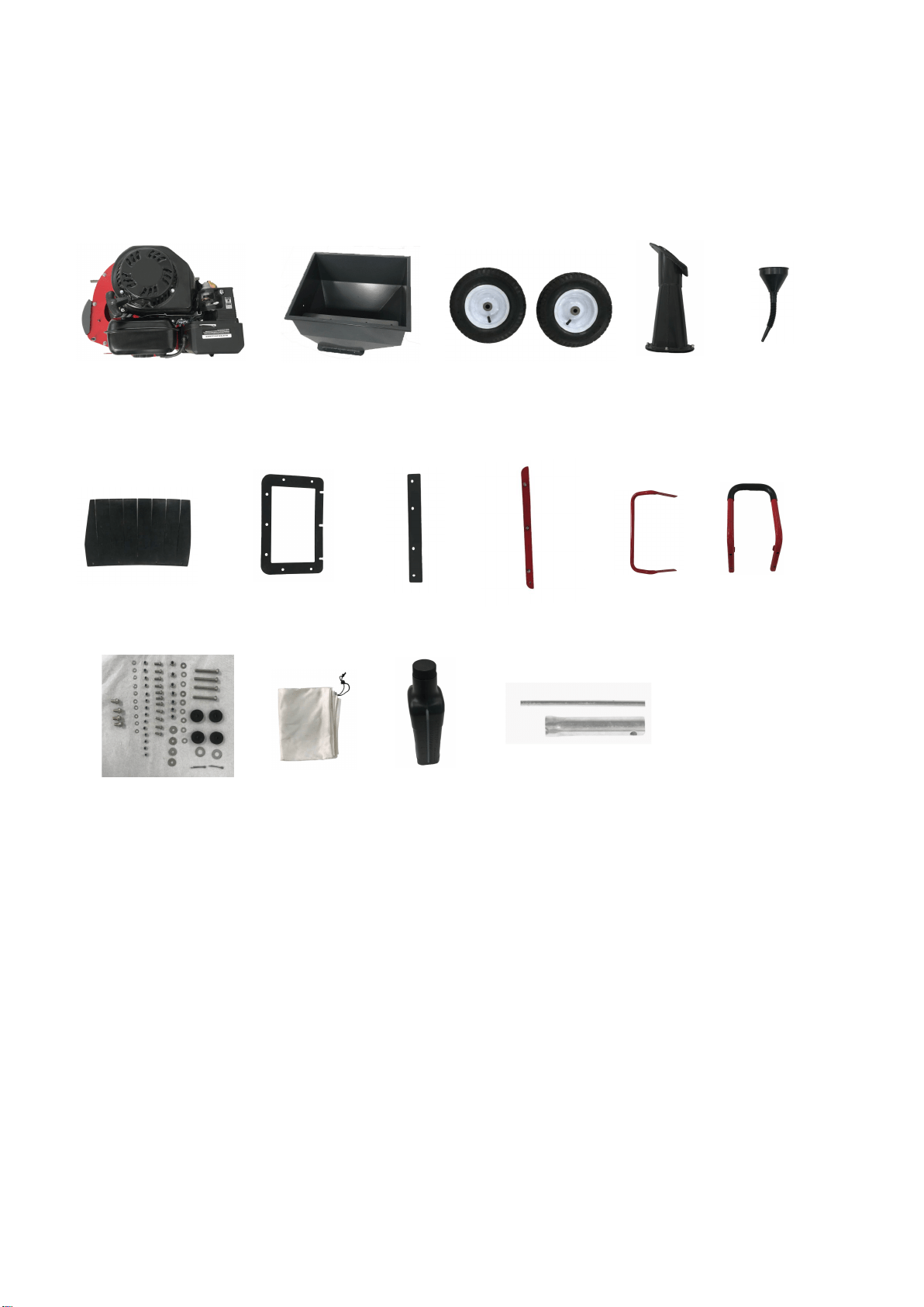
Unpacking
Unpack the chipper shredder and all its parts, and compare against the list below. Do not discard the
carton or any packaging materials. Please call 1-800-791-9458 or E-mail us at
[email protected] if any parts are damaged or missing.
Including:
1 Engine
2 Hopper
3 Wheel
4 Chipper chute
5 Funnel
6 Hopper Flap
7 Hopper Gasket
8 Batten
9 Locking strip
10 Handle
11 Support leg
12 Accessory bag for assembly
13 Discharge Bag
14 Oil bottle
15 Spark plug wrench
1 2 3
4 5
6 7 8 9
10 11
12 13 14 15
12
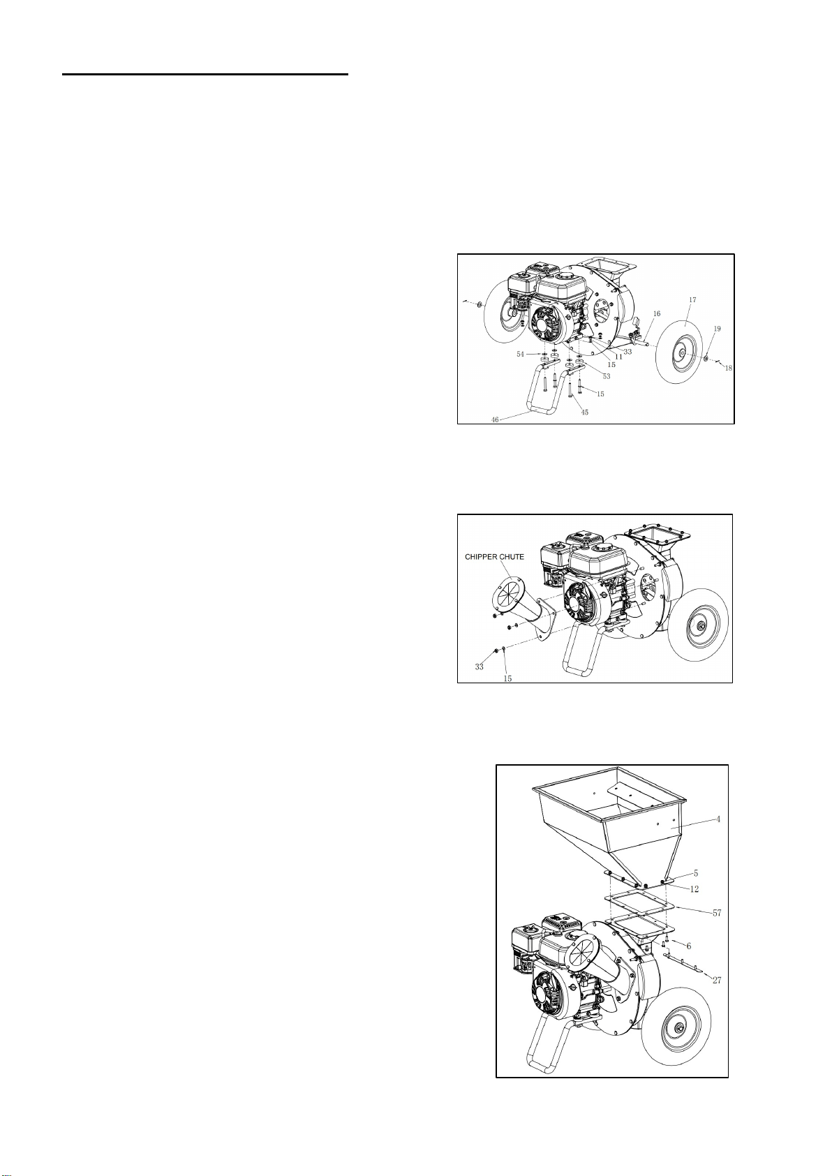
ASSEMBLY INSTRUCTION
The following section describes steps necessary to prepare the chipper shredder for use. If after
reading this section, you are unsure about how to perform any of the steps please call (800) 791-9458
Mon-Fri 9-5 EST for customer service. Failure to perform these steps properly can damage the
chipper shredder or shorten its lifespan.
1. Slide a Wheel (17) and Flat Washer (19) onto each end
of the Axle Assembly (16) at the lower rear of the unit.
Insert a Cotter Pin (18) through each end of the axle
and bend the Cotter Pin over to secure the Wheels in
place.
Secure the Support Leg (46) to the Engine using Bolts
(45) , Shock Absorbers (53), Large Flat Washers (54).
(See fig.3).
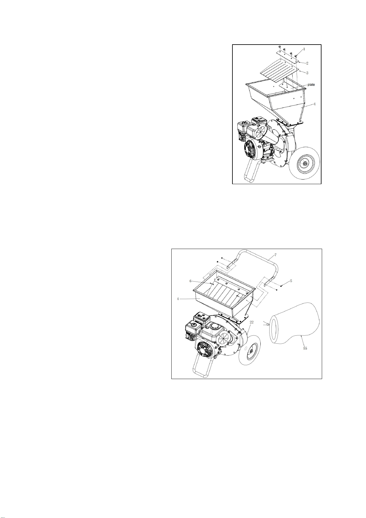
2. Position the chipper chute over the three threaded studs
protruding from the engine plate, and attach using
three flat washer and lock nuts M8 (15/33).
Rotate cone and cone base away from engine so cone
does not contact engine.
Tighten the flat washer and lock nuts M8 (15/33)
securely(See fig.4) .
3. Install the hopper (4) to the hopper gasket(57) with lock nut
M6(5) and flat washer(12) in the direction shown in the
figure.
Install the locking bar (27) to the hopper gasket(57) with bolt
M6×16 (6) in the direction shown in the figure (See fig.5).
Fig.3
Fig.4
Fig.5
13
4. Install the batten (2) and hopper Flap (3) to the hopper with four
flange bolts M8 x 16 (1) in the direction shown in the figure.Pay
attention to tighten (See fig.6)
5. Install the handle (7) with 4 lock nuts M6 (5) and 4 bolts M6 × 16 (6) to the hopper. The bolt goes
through the hopper.
To attach the Discharge Bag (55), lift the Discharge Port Cover (22) and attach the Bag onto the
discharge port using the rope tie (See fig.7) .
Fig.6
Fig.7
14
OPERATION
WARNING: Read the entire important safety information section at the beginning of
this manual including all text under subheadings therein before set up or use of this
product.
PRE-START CHECKS
Inspect engine and equipment looking for damaged, loose, and missing parts before set up and
starting. If any problems are found, do not use equipment until fixed properly.
Checking and Filling Engine Oil
NOTICE: Your Warranty is VOID if the engine’s crankcase is not properly filled with oil before each
use. Before each use, check the oil level. Engine will not start with low or no engine oil.
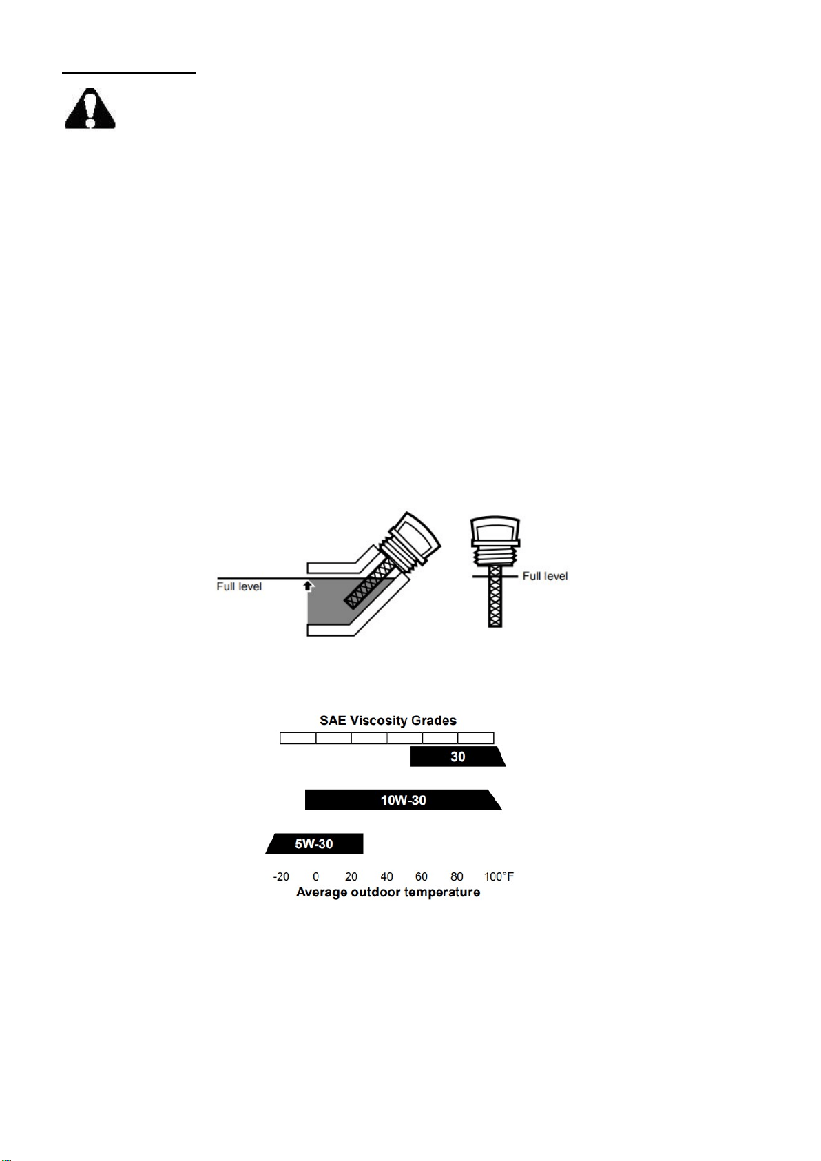
1. Make sure the engine is stopped and is level.
2. Close the Fuel Valve.
3. Clean the top of the Dipstick and the area around it. Remove the Dipstick by turning it
counterclockwise, and wipe it off with a clean, lint free rag.
4. The oil capacity of the engine crankcase is 16.9 fl. oz. Reinsert the Dipstick without threading it in
and remove it to check the oil level. The oil level should be up to the full level as shown above.
5. If the oil level is at or below the low mark add the appropriate type of oil until the oil level is at the
proper level. SAE 10W-30 oil is recommended for general use. Other viscosities shown in the
chart may be used when the average temperature in your area is within the indicated range.
6.Thread the dipstick back in clockwise.
NOTICE: Do not run the engine with too little oil. Engine will shut off if engine oil level is too low.
Fig.8
Fig.9
15
Checking and Filling Fuel
WARNING: TO PREVENT SERIOUS INJURY FROM FIRE:
Fill the fuel tank in a well-ventilated area away from ignition sources. If the engine is hot
from use, shut the engine off and wait for it to cool before adding fuel. Do not smoke.
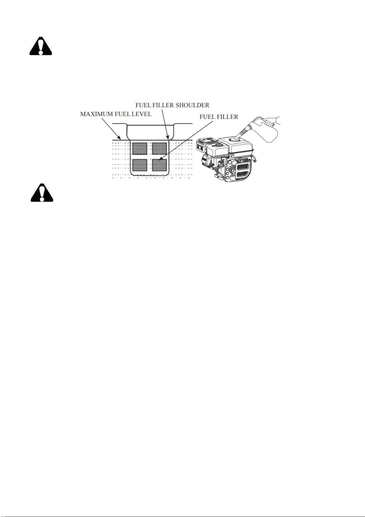
1. Remove the fuel tank cap and check fuel level.
2. If the level is too low, refuel the tank, remember adding fuel not over the fuel upper level.
WARNING:
1. Gasoline is extremely flammable and is explosive under certain conditions.
2. Refueling in a well-ventilation area with the engine stopped. Do not smoke and allow flames or
sparks in the area where gasoline is stored or where the fuel tank is refueled.
3. Do not overfill the fuel tank (there should be no fuel in the filling neck). After refueling, make sure
the fuel tank cap is set back securely.
4. Be careful not to spill fuel when refueling. Spilled fuel or fuel vapor may ignite. If any fuel is
spilled, make sure the area is dry before starting the engine.
5. Avoid repeated or prolonged contact with skin or breathing of fuel vapor. Keep out of reach of
children.
Use fresh (within 30 days from purchase), lead-free gasoline with a minimum of 87 octane rating. Do
not mix oil with gasoline.
To add gasoline, follow these steps:
1. Make sure the chipper shredder is on a level surface.
2. Unscrew fuel tank cap and set aside. NOTE: The fuel cap may be tight and hard to unscrew.
3. Slowly add unleaded gasoline to the fuel tank. Be careful not to overfill. The capacity of the fuel
tank is 0.95 gallons.
NOTE: Do not fill the fuel tank to the very top. Gasoline will expand and spill over during use
even with the fuel cap in place.
4. Reinstall fuel cap and wipe clean any spilled gasoline with a dry cloth.
IMPORTANT:
Never use an oil/gasoline mixture.
Never use old gasoline.
Avoid getting dirt or water into the fuel tank.
Gasoline can age in the tank and make starting difficult. Never store chipper shredder for
extended periods of time with fuel in the tank or the carburetor.
16
STARTING THE ENGINE
Before Starting the Engine:
a. Inspect the equipment and engine.
b. Fill the engine with the proper amount and type of both stabilizer-treated unleaded gasoline and oil.
c. Clean debris from discharge area — engine will not start if discharge area is jammed.
d. Engage the Wheel Locks on both wheels to prevent Chipper/Shredder movement during use.
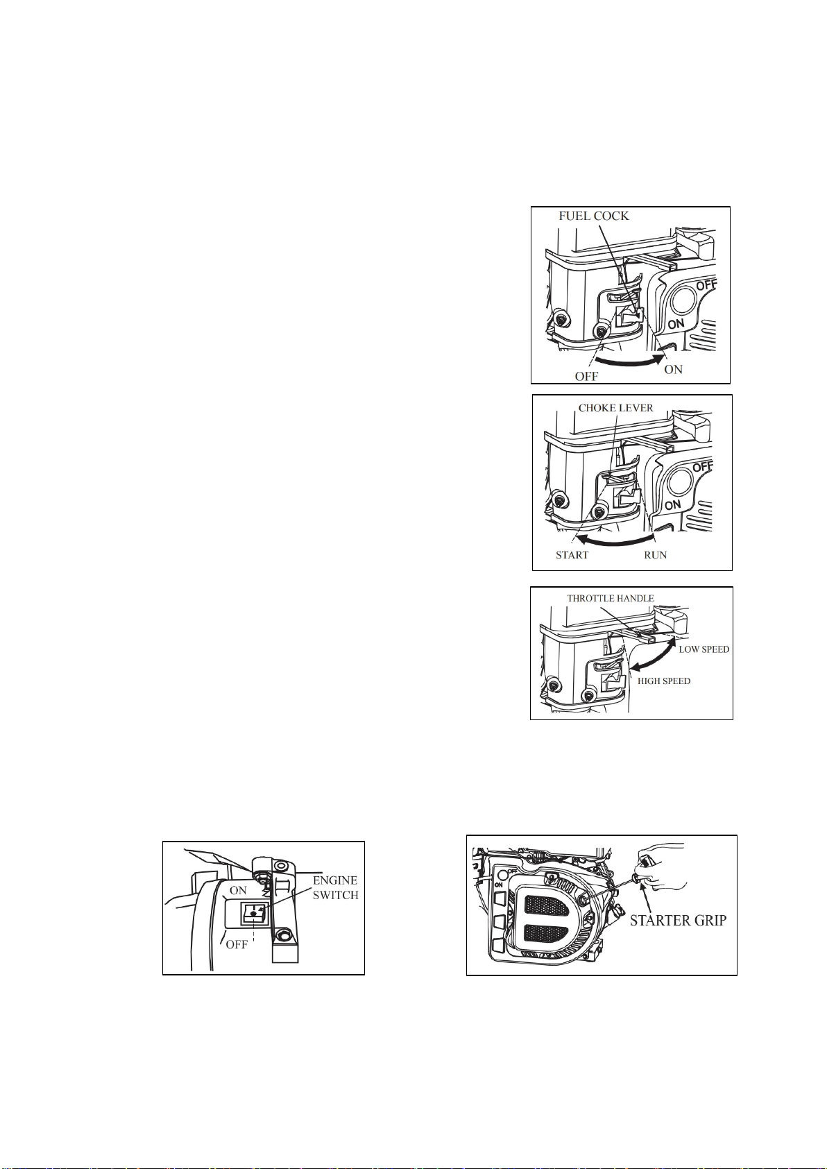
Manual start
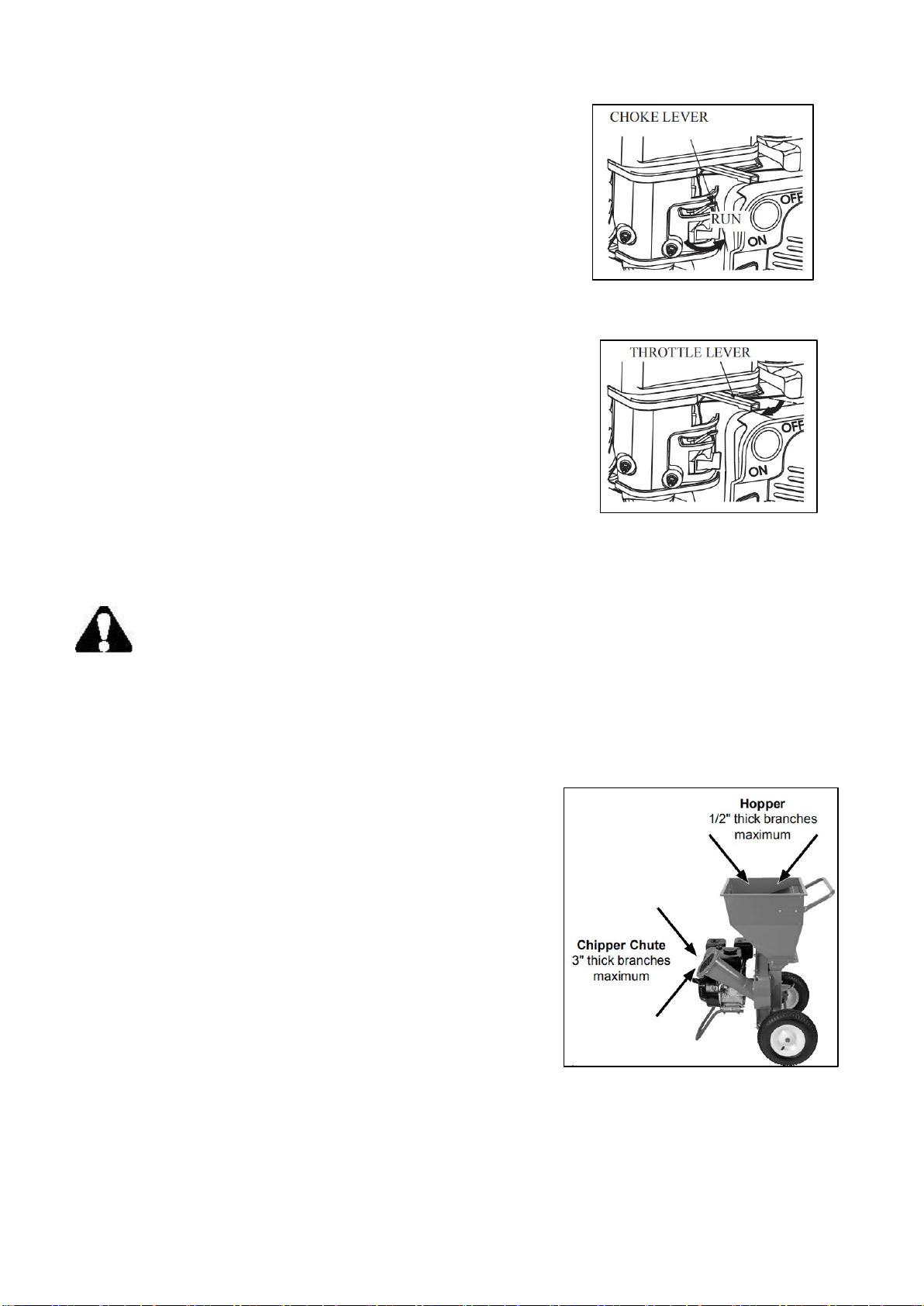
1. Turn the fuel cock to the “ON” position (See fig.11).
2. Turn the choke lever to the "START" position.
If the gasoline engine is hot, turn the choke lever to the "RUN"
position (See fig.12).
3. Move throttle handle to left a little (See fig.13).
4. Turn the engine switch to the “ON”(OPEN) position (See fig.14). Pull the starter grip lightly until
resistance is felt,then briskly (See fig.15).
Notice: Don’t allow the starter grip to snap back against the engine. Return it gently to prevent
damage to the starter.
Fig.11
Fig.12
Fig.13
Fig.14 Fig.15
17
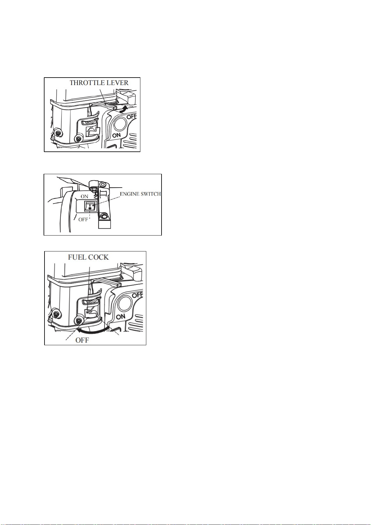
5. Preheat the engine and push back the choke lever to the "RUN"
Position (See fig.16).
6. Move the throttle lever to proper position to make the gasoline
engine run at required velocity (See fig.17).
Note: Moving the Choke Lever too fast could stall the engine.
IMPORTANT: Allow the engine to run at no load for five minutes
after each start-up so that the engine can stabilize.
CHIPPING AND SHREDDING
WARNING:
TO PREVENT SERIOUS INJURY: Do not force the Chipper/Shredder. Branches cannot
be thicker than 1/2" for Hopper and branches cannot be thicker than 3" for Chipper Chute.
Do not force branches into machine. The Chipper/Shredder is designed to draw material at the proper
rate.
Never use your hands to feed material directly into the Shredder.If needed, use a stick to push the
material into the Shredder.
1. Without putting your hands into Shredder (on top), slowly
drop material into the Hopper (one branch at a time). The
machine will pull the material in automatically.
2. The Chipper Chute is located on the side of the unit; only feed
one branch in at a time, larger end first.
3. Material discharges from the discharge port at high speed.
Make sure the Discharge Bag is properly attached before use.
Do not operate the Chipper/Shredder without the Discharge
Bag in place.
4. Do not allow Discharge Bag to overfill with processed
material. This may prevent proper discharge and can result in
kickback of material. Empty bag periodically as needed.
Note: Should Chipper/Shredder jam during use, immediately turn off the Engine. Wait until the
machine completely stops. Disconnect the Spark Plug. Clear the jam in the machine by shifting the
material with a long stick. Then, resume operation.
Fig.16
Fig.17
Fig.18
18
STOPPING THE ENGINE
1. To stop the engine in an emergency, turn the Engine Switch off.
2. Under normal conditions, use the following procedure:
a. Push right the throttle lever to low speed position.
b. Push the engine switch to the “OFF” position.
c. Set the fuel cock to “OFF” position.
NOTICE: Sudden stopping at high speed under heavy load is forbidden, otherwise damage will
result.
Fig.19
Fig.20
Fig.21
19
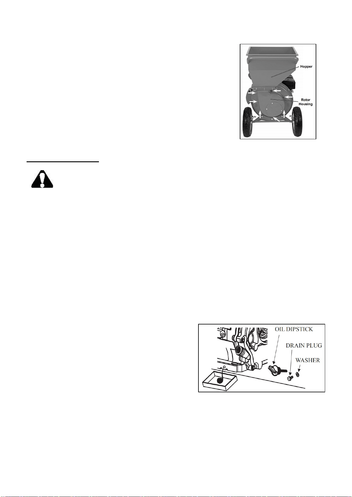
CLEANING AND STORING
1. After every use and before storing, clean debris out of machine:
a. Remove spark plug cap from spark plug.
b. Allow engine to cool completely.
c. Remove the Lock Nuts and Washers holding the Hopper/Rotor
Housing assembly in place (See fig.22).
d. Clear all debris out of the Main Housing and discharge port.
e. Replace the Hopper/Rotor Housing assembly and secure in place
using the Washers and Lock Nuts.
2. Store the Chipper/Shredder in a dry indoor location that does not allow
access by children.
MAINTENANCE
WARNING:
TO PREVENT SERIOUS INJURY FROM ACCIDENTAL STARTING:
Turn the power Switch of the equipment to its “OFF” position, wait for the engine to
cool, and disconnect the spark plug cap before performing any inspection, maintenance, or cleaning
procedures.
TO PREVENT SERIOUS INJURY FROM EQUIPMENT FAILURE:
Do not use damaged equipment. If abnormal noise, vibration, or excess smoking occurs, have the
problem corrected before further use.
Follow all service instructions in this manual. The engine may fail critically if not serviced properly.
Many maintenance procedures, including any not detailed in this manual, will need to be performed
by a qualified technician for safety. If you have any doubts about your ability to safely service the
equipment or engine, have a qualified technician service the equipment instead.
The engine must be properly maintained to ensure its operation be safe, economy and trouble-free, as
well as eco-friendly.
In order to keep your gasoline engine in good working condition, it must be periodically serviced. The
following maintenance schedule and routine inspection procedures must be carefully followed.
CHANGING/ ADDING OIL
Replacement of engine oil (see page 14 to check
method). Drain the engine oil rapidly and completely
out when the engine is hot.
Turn off the oil filler cap and drain plug to drain
engine oil thoroughly. Reinstall the drain plug and
screw in securely.
Fill the specified engine oil up to the upper level mark.
Reinstall the oil filler cap.
NOTICE: Do not dump oil containers or discarded engine oil into rubbish boxes or onto the ground.
For the sake of environmental protection, we suggest you take in discarded engine oil with a closed
container and bring to local recycling station.
Fastener Locations
Fig.22
Fig.23
20
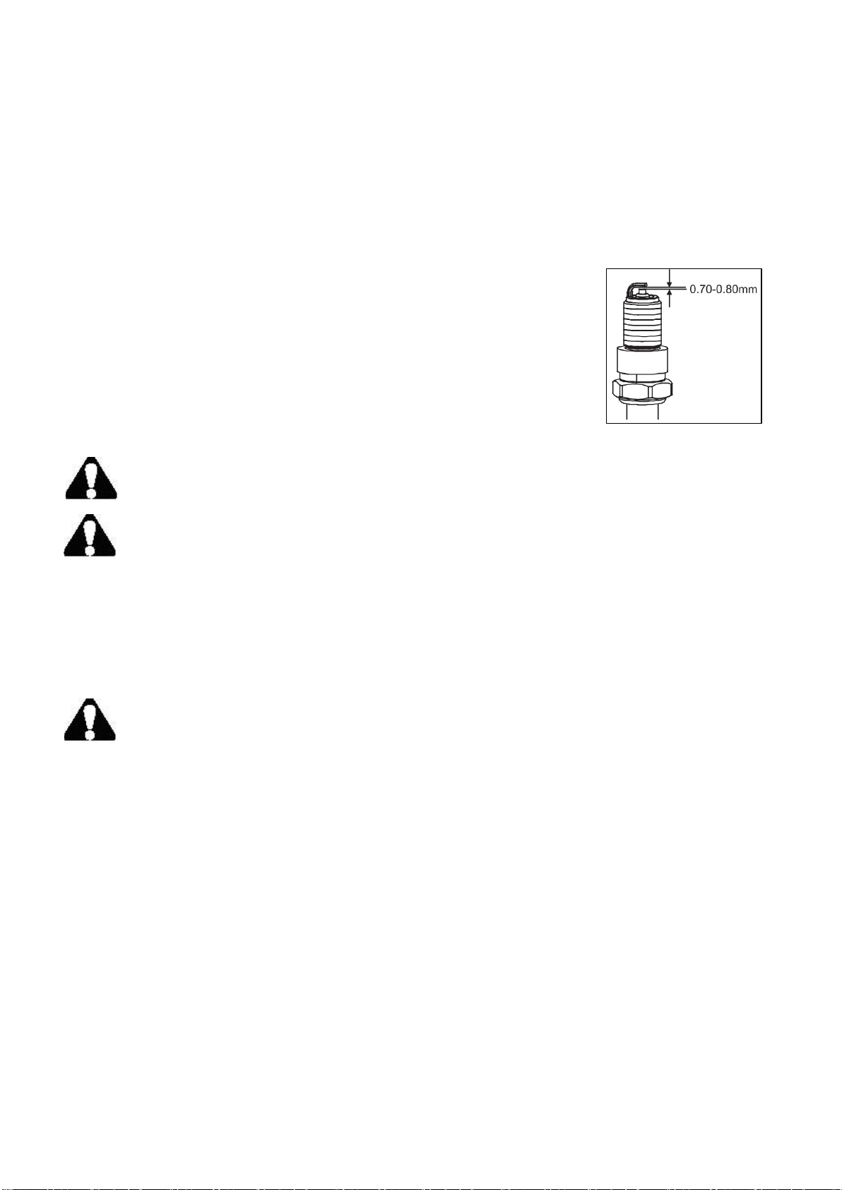
SPARK PLUG MAINTENANCE
Spark plug type: BPR6ES (NGK) or NHSP LD F7RTC
In order to ensure the engine normal running, gap of the spark plug must be correct and no deposit
around the spark plug.
Remove the spark plug cap.
Clear away dirt around the spark plug base.
Dismantle the spark plug with a spark plug wrench.
Visually check the spark plug. Clean with a steel brush. If the insulator is damaged, replace the
spark plug instead.
Measure the spark plug clearance with a feeler. The clearance should be
0.7~0.8mm. If adjustment is necessary, bend the side electrode carefully.
Check if the spark plug gasket is in good conditions. In order to screw
thread misplace, screw in by hand.
Screw on the spark plug to the bottom first by hand and then screw in by a
spark plug wrench and compress the gasket.
-- If a new spark plug is used, more twist 1/2 turns after compressing the
gasket.
-- If reinstalling the used spark plug, just more twist 1/8-1/4 turns.
WARNING: Don’t touch the muffler in running and just gasoline engine stopping
stage to avoid burn.
WARNING: The spark plug must be tightened securely, or it may become very hot to
damage the engine.
AIR FILTER MAINTENANCE
A dirty air filter can restrict air flowing into the carburetor. To keep the carburetor in good working
conditions, please service the air filter periodically(clean air filter element after engine running
20h).If operating the engine in extremely dusty area, the job should be done more often.
WARNING: Never clean the air filter element with gasoline or low flash-point
detergents, or explosion may happen.
NOTICE: Never run the engine without an air filter, because air with dirt and dust entering the
engine can speed up the engine wear.
1. Remove the air filter cover off and take the element out.
2. Cleaning:
•For paper filters:
Wash the element with home detergents and warm water (or non-flammable or high flash-point
cleansing solvents) and dry up.
•For foam filters:
Soak in clean engine oil until saturated. Squeeze out excess oil, otherwise, the engine will smoke in
Starting stage.
3. Clean the air filter cover and inner surface with wet cloth, be careful not to allow the dust entering
into the carburetor.
4. Reinstall the element and put the air filter cover on.
Fig.24

21
SHREDDING HAMMER INSPECTION
1. Remove the Bolts , Lock Washers , and Flat Washers securing the circular Access Panel located on
the back of the Rotor Housing , then remove the Panel.
2. Inspect the Rectangular Hammers and L-Hammers on the cutting edges for wear or damage.
3. If necessary, have the Hammers replaced by a qualified technician.
CHIPPER BLADE INSPECTION
1. Remove the Lock Nuts and Washers securing the Chipper Chute to the Chipper/Shredder. Remove
the Chute to gain access to the Chipper Blades.
2. Slowly pull the Starter Handle to rotate the Rotor Assembly into a position where the Blades
can be inspected for wear or damage.
3. If necessary, have the Chipper Blades sharpened or replaced by a qualified technician.
MAINTENANCE SCHEDULE
NOTICE:
If the gasoline engine frequently work under high temperature or heavy load, change the oil every
25 hours.
If the engine frequently work under dusty or other severe circumstances, clean the air filter
element every 10 hours; If necessary, change the air filter element every 25 hours.
The maintenance period and the exact time (hour), the one which comes first should govern.
If you have missed the scheduled time to maintain your engine, do it as soon as possible.
Frequency
Items
Each
time
Fi
rst 1 month or
first
20hrs of
operation
Thereafter, every
3 months or every
50hrs of opera- tion
Every year
or
every 100
hrs of
operation
Engine oil Check- Refill √
Replace
√
√
Reduction gear
oil(if equipped)
Oil level check √
Replace √ √
Air filter
element
Check
√
Clean
√
Replace
√
Deposit Cup( if
equipped) Clean √
Spark Plug Check - adjust √*
Spark arrester Clean √
Idling ( if
equipped)** Check - adjust √
Valve clearance
** Check-adjust √
Fuel tank & fuel
filter ** Clean √
Fuel line Check Every 2 years( change if necessary)
Cylinder head,
piston
Clean up carbon
**
<
225cc
,
Every 125hrs
≥225cc
,
Every 250hrs
*These items should be replaced if replacement needed.
**These items should be maintained and repaired by our authorized dealer, unless the
owner has appropriate tools and is proficient with mechanical maintenance.
22
TRANSPORT&STORAGE
CAUTION: Never place any type of storage cover or tarp on the machine while it is still hot.
NOTICE: Do not incline the engine so as to avoid fuel’s spill. Spilled fuel or fuel vapor may ignite to
cause fire.
If the engine is not kept in use for a long time, be sure to store it properly.
1. Make sure the storage area is dry and free of dust.
2. Turn the fuel cock to “OFF” position, set a proper container under the
carburetor.
3. Open the fuel cock to completely train gasoline out of the fuel tank.
4. Reinstall the oil drain plug back and tighten it.
5. Drain the oil out of the gasoline engine.
6. Remove the spark plug. Fill about a spoon of fresh engine oil onto the
cylinder. Crank the engine up to distribute engine oil evenly. Reinstall
the spark plug.
7. Cover the engine to protect dust entering.
Please maintain according to following table when reuse after storing.
Storing time Maintaining procedure is commended in order to prevent starting
difficult.
1 month Don’t need to prepare.
1-2 month Drain the used gasoline out and add the fresh gasoline.
2 months to 1 year Drain the used gasoline out and add the fresh gasoline
①Drain the gasoline out of the carburetor cup.
②Drain the gasoline out of the sediment bowl.
1 year over
Drain the used gasoline out and add the fresh gasoline
①Drain the gasoline out of the carburetor cup.
②Drain the gasoline out of the sediment bowl.
After removing out of the storage, first, drain the used gasoline to
proper container, and don’t start before adding fresh gasoline.
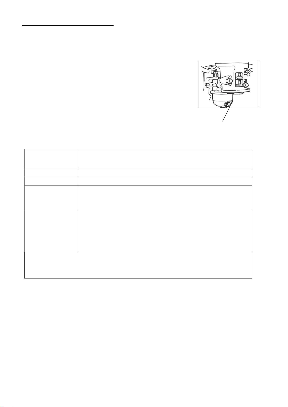
Loosen the oil drain bolt and completely drain the gasoline out of the carburetor to proper container and screw
the oil drain bolt down. Remove the sediment bowl after closing fuel cock, and completely pour the gasoline
out the sediment bowl. Finally reinstall the sediment bowl back and screw it down.
Fig.25
CARBURETOR OIL DRAIN PLUG

23
TROUBLESHOOTING
Follow all safety precautions whenever diagnosing or servicing the equipment or
engine.
problem possible Causes probable Solutions
Engine will not start
FUEL RELATED:
1. No fuel in tank or fuel valve closed.
2. Choke not in START position, cold engine.
3. Gasoline with more than 10% ethanol used.
(E15, E20, E85, etc.)
4. Low quality or deteriorated, old gasoline.
5. Carburetor not primed.
6. Dirty fuel passageways.
7. Carburetor needle stuck.
Fuel can be smelled in the air.
8. Too much fuel in chamber. This can be caused by
the carburetor needle sticking.
9. Clogged Fuel Filter.
FUEL RELATED:
1. Fill fuel tank with fresh 87+ octane stabilizer-
treated unleaded gasoline and open fuel valve.
Do not use gasoline with more than 10%
ethanol (E15, E20, E85, etc.).
2. Move Choke to START position.
3. Clean out ethanol rich gasoline from fuel
system. Replace components damaged by
ethanol. Use fresh 87+ octane stabilizer- treated
unleaded gasoline only.
Do not use gasoline with more than 10%
ethanol (E15, E20, E85, etc.).
4. Use fresh 87+ octane stabilizer-treated
unleaded gasoline.
Do not use gasoline with more than 10%
ethanol (E15, E20, E85, etc.).
5. Pull on Starter Handle to prime.
6. Clean out passageways using fuel additive. Heavy
deposits may require further cleaning.
7. Gently tap side of carburetor float
chamber with screwdriver handle.
8. Turn Choke to RUN position. Remove spark
plug and pull the start handle several times to air
out the chamber. Reinstall
spark plug and set Choke to START position.
9. Replace Fuel Filter.
IGNITION (SPARK) RELATED:
1. Spark plug cap not connected securely.
2. Spark plug electrode wet or dirty.
3. Incorrect spark plug gap.
4. Spark plug cap broken.
5. Incorrect spark timing or faulty ignition system.
IGNITION (SPARK) RELATED:
1. Connect spark plug cap properly.
2. Clean spark plug.
3. Correct spark plug gap.
4. Replace spark plug cap.
5. Have qualified technician diagnose/
repair ignition system.
COMPRESSION RELATED:
1. Cylinder not lubricated.
Problem after long storage periods.
2. Loose or broken spark plug.
(Hissing noise will occur when
trying to start.)
3. Loose cylinder head or damaged head gasket.
(Hissing noise will occur when trying to start.)
4. Engine valves or tappets mis-adjusted or stuck.
COMPRESSION RELATED:
1. Pour tablespoon of oil into spark plug
hole. Crank engine a few times
and try to start again.
2. Tighten spark plug.
If that does not work, replace spark plug. If
problem persists, may have head gasket
problem, see #3.
3. Tighten head.
If that does not remedy problem,
replace head gasket.
4. Have qualified technician adjust/
repair valves and tappets.
ENGINE OIL RELATED:
1. Low engine oil.
2. Engine mounted on slope,
triggering low oil shutdown.
ENGINE OIL RELATED:
1. Fill engine oil to proper level.
Check engine oil before EVERY use.
2. Operate engine on level surface.
Check engine oil level.

24
problem possible Causes probable Solutions
Engine misfires 1. Spark plug cap loose.
2. Incorrect spark plug gap or
damaged spark plug.
3. Defective spark plug cap.
4. Old or low quality gasoline.
5. Incorrect compression.
1. Check cap and wire connections.
2. Re-gap or replace spark plug.
3. Replace spark plug cap.
4. Use only fresh 87+ octane stabilizer-treated
unleaded gasoline.
Do not use gasoline with more than 10%
ethanol (E15, E20, E85, etc.).
5. Diagnose and repair compression. (Use
Engine will not start:
COMpRESSION RELATED section.)
Engine stops
suddenly
1. Fuel tank empty or full of impure or low quality
gasoline.
2. Low oil shutdown.
3. Defective fuel tank cap creating vacuum,
preventing proper fuel flow.
4. Faulty magneto.
5. Disconnected or improperly
connected spark plug cap.
1. Fill fuel tank with fresh 87+ octane stabilizer-
treated unleaded gasoline.
Do not use gasoline with more than 10%
ethanol (E15, E20, E85, etc.).
2. Fill engine oil to proper level.
Check engine oil before EVERY use.
3. Test/replace fuel tank cap.
4. Have qualified technician service magneto.
5. Secure spark plug cap.
Engine stops when
under heavy load
1. Dirty air filter
2. Engine running cold.
1. Clean element.
2. Allow engine to warm up prior to
operating equipment.
Engine knocks 1. Old or low quality gasoline.
2. Engine overloaded.
3. Incorrect spark timing, deposit buildup, worn
engine, or other mechanical problems.
1. Fill fuel tank with fresh 87+ octane stabilizer-
treated unleaded gasoline.
Do not use gasoline with more than 10%
ethanol (E15, E20, E85, etc.).
2. Do not exceed equipment’s load rating.
3. Have qualified technician diagnose
and service engine.
Engine backfires
After sudden impact,
engine will run, but
equipment will not
operate
1. Impure or low quality gasoline.
2. Engine too cold.
3. Intake valve stuck or overheated engine.
4. Incorrect timing.
Shaft key or other shear pin broken
by impact to disconnect engine and
limit damage.
1. Fill fuel tank with fresh 87+ octane stabilizer-
treated unleaded gasoline.
Do not use gasoline with more than 10%
ethanol (E15, E20, E85, etc.).
2. Use cold weather fuel and oil additives to
prevent backfiring.
3. Have qualified technician diagnose
and service engine.
4. Check engine timing.
Have qualified technician check and replace
broken shaft key or other shear pins.
Follow all safety precautions whenever diagnosing or servicing the equipment or
engine.
25
Follow all safety precautions whenever diagnosing or servicing the equipment or engine.
problem possible Causes probable Solutions
Chipping action
slow, or Engine
stalling
1. Branch diameter too thick.
2. Throttle set too low.
1. Do not process branches over 3" diameter.
2. Adjust throttle to increase Engine speed.
Branch vibrates
and moves
excessively when
chipping
1. Branches are too hard and/or dried out.
2. Chipping blades are dull or damaged.
1. Material is not suitable for chipping.
2. Have qualified technician
service Chipper/Shredder.
Engine runs but
no material is
processed
1. Chipper/Shredder is jammed.
2. Throttle set too low.
1. Clear all debris out of the Main
Housing and discharge port.
2. Adjust throttle to increase Engine speed.
Unusual noise
and/or vibration
during use
1. Rotor Assembly area clogged with material.
2. Hammers loose, damaged, or
obstructed by debris.
1.
Stop adding material to Hopper/ Chipper
Chute–allow Chipper/Shredder to clear
itself before continuing.
2.
Have qualified technician
service Chipper/Shredder.
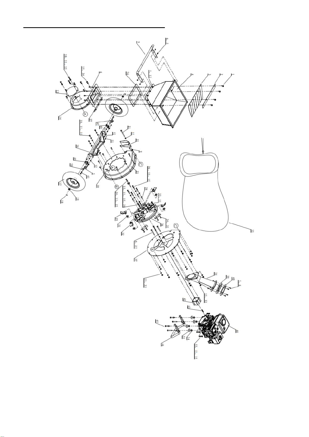
26
EXPLODED VIEW AND PARTS LIST

27
Item
Stock# Description Qty.
Item
Stock# Description Qty.
1 PS1130-001 Flange Bolt M8 x
16 4
29 PS1130-029
L-Hammer 2
2 PS1130-002 Batten 1
30 PS1130-030
Socket Head Cap Screw
M8x20 2
3 PS1130-003 Hopper Flap 1
31 PS1130-031
Washer 4
4 PS1130-004 Hopper 1
32 PS1130-032
Rectangular Hammer 2
5 PS1130-005 Lock Nut M6 22
33 PS1130-033
Lock Nut M8 31
6 PS1130-006 Bolt M6 x 16 15
34 PS1130-034
Socket Head Cap Screw
M8x25 4
7 PS1130-007 Handle 1
35 PS1130-035
Chipper Blade 2
8 PS1130-008 Bolt
5/16-24UNF×80 4
36 PS1130-036
Rotor Assembly 1
9 PS1130-009 Flange Nut M8 1
37 PS1130-037
Engine Plate 1
10 PS1130-010 Bolt M8 x 16 6
38 PS1130-038
Chipper Chute 1
11 PS1130-011 Spring washer 8 25
39 PS1130-039
Chipper Chute Flap 1
12 PS1130-012 Flat Washer 6 18
40 PS1130-040
Chipper Chute Mounting
Ring 1
13 PS1130-013 Access Panel 1
41 PS1130-041
Spring washer 6 2
14 PS1130-014 Rotor Housing 1
42 PS1130-042
Engine Mounting Block 1
15 PS1130-015 Flat Washer 8 50
43 PS1130-043
Engine Flat Key 1
16 PS1130-016 Axle Assembly 1
44 PS1130-044
Engine 1
17 PS1130-017 Wheel 2
45 PS1130-045
Bolt M8 x 65 4
18 PS1130-018 Cotter Pin 4x30 2
46 PS1130-046
Support Leg 1
19 PS1130-019 Flat Washer 16 2
47 PS1130-047
Left Brake Lever 1
20 PS1130-020 Bolt M8 x 20 10
48 PS1130-048
Left Brake Pad 1
21 PS1130-021 Socket Head Cap
Screw M8 x 100 1
49 PS1130-049
Right Brake Pad 1
22 PS1130-022 Discharge Port
Cover 1
50 PS1130-050
Right Brake Lever 1
23 PS1130-023 Main Housing 1
51 PS1130-051
Socket Head Cap Screw
M6 x 16 2
24 PS1130-024
Socket Head Cap
Screw
5/16-24UNF×130
1
52 PS1130-052
Socket Head Cap Screw
M6 x 25 2
25 PS1130-025 Cutter plate 1
53 PS1130-053
Shock Absorber 4
26 PS1130-026 Socket Head Cap
Screw M8x50 4
54 PS1130-054
Flat Washer 8 4
27 PS1130-027 Locking strip 1
55 PS1130-055
Discharge Bag 1340x540
1
28 PS1130-028 Long Spacer
Bushing 4
56 PS1130-056
Hopper Gasket 1
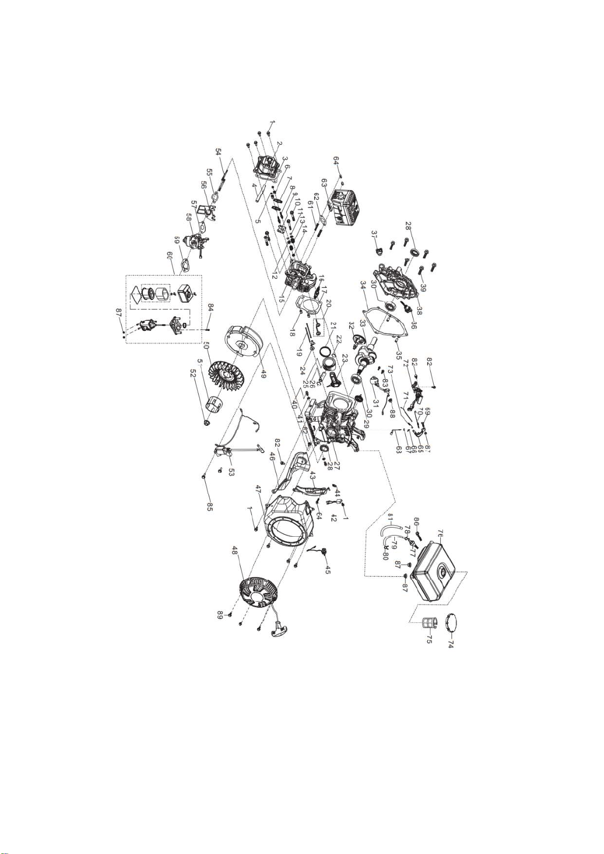
28
Engine explode view and part list

29
Item Stock# Description Qty.
1 90001-0612-01 BOLT 9
2 12410-Z440110-0099 COVER SUBASSEMBLY, CYLINDER HEAD
1
3 12004-Z440110-00A0 GASKET, CYLINDER HEAD COVER 1
4 17004-Z010310-0000 TUBE, BREATHER 1
5 14312-Z010110-0000 NUT, VALVE LOCK 2
6 14314-Z010110-0000 NUT, VALVE ADJUSTING 2
7 14311-Z010110-0000 ROCKER, VALVE 2
8 14313-Z010110-0000 BOLT, ROCKER SHAFT 2
9 14090-Z010110-0000 PLATE SUBASSEMBLY, LIFTER STOPPER 1
10 12003-Z010110-0000 BOLT, CYLINDER HEAD 4
11 12109-Z810110-0000 CLAMP, VALVE LOCK 4
12 12112-Z810210-0000 SEAT, VALVE SPRING 2
13 12103-Z010110-0000 SPRING, VALVE 2
14 12101-Z810210-0000 GUIDE, SEAL 1
15 12140-Z810210-00A0 HEAD SUBASSEMBLY, CYLINDER 1
16 30010-Z010210-0000 PLUG, SPARK 1
17 12131-Z950110-0000 GASKET, CYLINDER HEAD 1
18 90502-1114-00 PIN 2
19 14071-Z440110-0000 LIFTER, VALVE 2
20 12110-Z810120-0099 VALVES SET 1
21 13200-Z140210-00A9 RING ASSY, PISTON 1
22 13122-Z010110-0000 CLIP, PISTON PIN 2
23 13010-Z440210-00A9 ROD, CONNECTING 1
24 14081-Z040110-0000 TAPPET, VALVE 2
25 13111-Z140220-0099 PISTON 1
26 13121-Z010110-0000 PIN, PISTON 1
27 11310-Z530420-00A9 CRANKCASE SUBASSEMBLY. 1
28 90682-Z300110-0000 SEAL, OIL 2
29 16400-Z010110-0000 GEAR ASSY, GOVERNOR 1
30 90547-0205-CL BEARIN, DEEP GROOVE BALL 2
31 37060-Z010120-0000 SENSOR, ENGINE OIL 1
32 14200-Z530110-0099 CAMSHAFT ASSY. 1
33 13300-Z530210-0000 CRANKSHAFT ASSY. 1

30
Item Stock# Description Qty.
34 11001-Z440110-00A0
GASKET, CRANKCASE 1
35 90502-0912-00 PIN 2
36 15010-Z010130-Q500
DIPSTICK SUBASSEMBLY, OIL 1
37 15030-Z010130-Q500
PLUG SUBASSEMBLY, ENGINE OIL 1
38 11411-Z440410-00A0
COVER, CRANKCASE 1
39 90001-0832-01 BOLT 6
40 11007-Z010110-0000 BOLT, DRAIN PLUG 2
41 90408-Z010110-0000 WASHER, FLAT 2
42 37050-Z010210-0000 PROTECTOR, OIL 1
43 19340-Z010120-0000 SHIELD,LOWER 1
44 90740-Z010110-0000 COLLAR 1
45 35540-Z010410-QG00
SWITCH SUBASSEMBLY, STOP ENGINE 1
46 19304-Z010610-0000 SHROUD, CYLINDER BODY 1
47 28110-Z010410-H700
SHROUD 1
48 28200-Z440110-H700
STARTER ASSY, RECOIL 1
49 13510-Z440410-0000 FLYWHEEL SUBASSEMBLY 1
50 19352-Z440110-00A0
IMPELLER 1
51 28002-Z010310-0000 PULLEY,STARTER 1
52 13501-Z010110-0000 NUT, FLYWHEEL 1
53 30400-Z010210-0000 COIL, IGNITION 1
54 90204-Z010310-0000 BOLT 2
55 16002-Z050110-0000 GASKET, CARBURETOR INSULATOR 1
56 16003-Z010110-0000 PLATE, CARBURETOR INSULATOR 1
57 16001-Z010110-0000 GASKET, CARBURETOR 1
58 16100-Z530610-00M0
CARBURETOR ASSY. 1
59 17001-Z010210-0000 GASKET, AIR CLEANER 1
60 17100-Z010210-0000 CLEANER, AIR 1
61 90203-Z010110-0000 BOLT 2
62 18001-Z440110-00A0
GASKET, EXHAUST OUTLET 1
63 18100-Z012410-H300
MUFFLER ASSY. 1
64 90303-0800-31 NUT 2
65 16070-Z010110-0000 SUPPORT SUBASSEMBLY, GOVERNOR 1
66 90501-Z010110-0000 PIN 1

31
Item Stock# Description Qty.
67 90408-Z010210-0000 WASHER, FLAT 1
68 16061-Z010110-0000 ARM, GOVERNOR 1
69 16072-Z010110-0000 BOLT, GOVERNOR SUPPORT 1
70 16063-Z050510-0000 SPRING, GOVERNOR 1
71 16062-Z010110-0000 ROD, GOVERNEOR 1
72 16520-Z010430-0001 CONTROL ASSY, THROTTLE 1
73 16012-Z010110-0000 SPRING, THROTTLE VALVE RETURNING 1
74 16730-Z440810-LK00 COVER, FUEL TANK 1
75 16652-Z010710-00A0 STRAINER,FUEL 1
76 16620-Z440410-H70P TANK, FUEL 1
77 16680-Z010210-0000 OUTLET SUBASSEMBLY, FUEL TANK OIL
1
78 90685-Z080110-0000 CLAMP 1
79 90686-Z010710-00M0 TUBE, FUEL 1
80 90685-Z030610-0400 CLAMP 1
81 30431-Z010110-0000 JACKET, RUBBER 1
82 90001-0610-01 BOLT 4
83 90001-0614-01 BOLT 2
84 90001-0616-01 BOLT 1
85 90001-0625-01 BOLT 2
86 90001-0630-01 BOLT 1
87 90305-0600-31 NUT 5
88 90305-Z010210-0100 NUT 1
89 90001-0608-01 BOLT 3

32
TWO (2) YEARS LIMITED WARRANTY
PowerSmart is committed to building equipment that will provide years of dependable service. Our warranties
are consistent with our commitment and dedication to quality.
TWO (2) YEARS LIMITED WARRANTY OF POWER SMART PRODUCTS FOR HOME USE.
PowerSmart (“Seller") warrants to the original purchaser only, that all PowerSmart consumer power tools will
be free from defects in material or workmanship for a period of two (2) years from date of purchase. If the
tool(s) is used while providing professional or commercial services, the warranty coverage shall be for a
maximum of (90) days.
SELLER’S SOLE OBLIGATION AND YOUR EXCLUSIVE REMEDY under this Two (2) Years Limited
Warranty and, to the extent permitted by law, any warranty or condition implied by law, shall be the repair or
replacement of parts, without charge, which are defective in material or workmanship and which have not been
misused, carelessly handled, or improperly repaired, by person(s) other than an Authorized Seller or Service
Center.
Please be aware that normal wear parts are not covered this warranty. This includes drive belts, blades and
discharge bags. Carburetor issues, and/or other damage found to be the result of stale, contaminated or
compromised fuel, is not covered under this limited warranty.
To make a claim under this Limited Warranty, you must return the entire power tool product; transportation
prepaid, to PowerSmart. The owner must include a legible copy of the original receipt, which shall list the date
of purchase, along with the company’s name where the product was purchased.
THIS LIMITED WARRANTY DOES NOT APPLY TO ANY ACCESSORY ITEMS INCLUDED WITH
THE TOOL SUCH AS CIRCULAR SAW BLADES OTHER RELATED ITEMS OR TO ANY
REPLACEMENT PARTS LISTED UNDER MAINTENANCE.
ANY IMPLIED WARRANTIES SHALL BE LIMITED IN DURATION TO TWO (2) YEARS FROM DATE
OF PURCHASE. SOME STATES IN THE U.S. AND SOME CANADIAN PROVINCES DO NOT ALLOW
LIMITATIONS ON HOW LONG AN IMPLIED WARRANTY LASTS, SO THE ABOVE LIMITATION
MAY NOT APPLY TO YOU.
IN NO EVENT SHALL SELLER BE LIABLE FOR ANY INCIDENTAL OR CONSEQUENTIAL
DAMAGES (INCLUDING BUT NOT LIMITED TO LIABILITY FOR LOSS OF PROFITS) ARISING
FROM THE SALE OR USE OF THIS PRODUCT. SOME STATES IN THE U.S. AND SOME CANADIAN
PROVINCES DO NOT ALLOW THE EXCLUSION OR LIMITATION OF INCIDENTAL OR
CONSEQUENTIAL DAMAGES, SO THE ABOVE LIMITATION OR EXCLUSION MAY NOT APPLY
TO YOU.
THIS LIMITED WARRANTY GIVES YOU SPECIFIC LEGAL RIGHTS, AND YOU MAY ALSO HAVE
OTHER RIGHTS WHICH VARY FROM STATE TO STATE IN THE U.S., PROVINCE TO PROVINCE IN
CANADA AND FROM COUNTRY TO COUNTRY.
Please call toll free at: 1-800-791-9458(M-F 9am – 5pm EST) Email: support@amerisuninc.com
PLEASE SAVE ALL OF YOUR ORIGINAL RECEIPTS. THIS WARRANTY IS VOID WITHOUT THEM.