
Loading ...
Loading ...
Loading ...
English
10
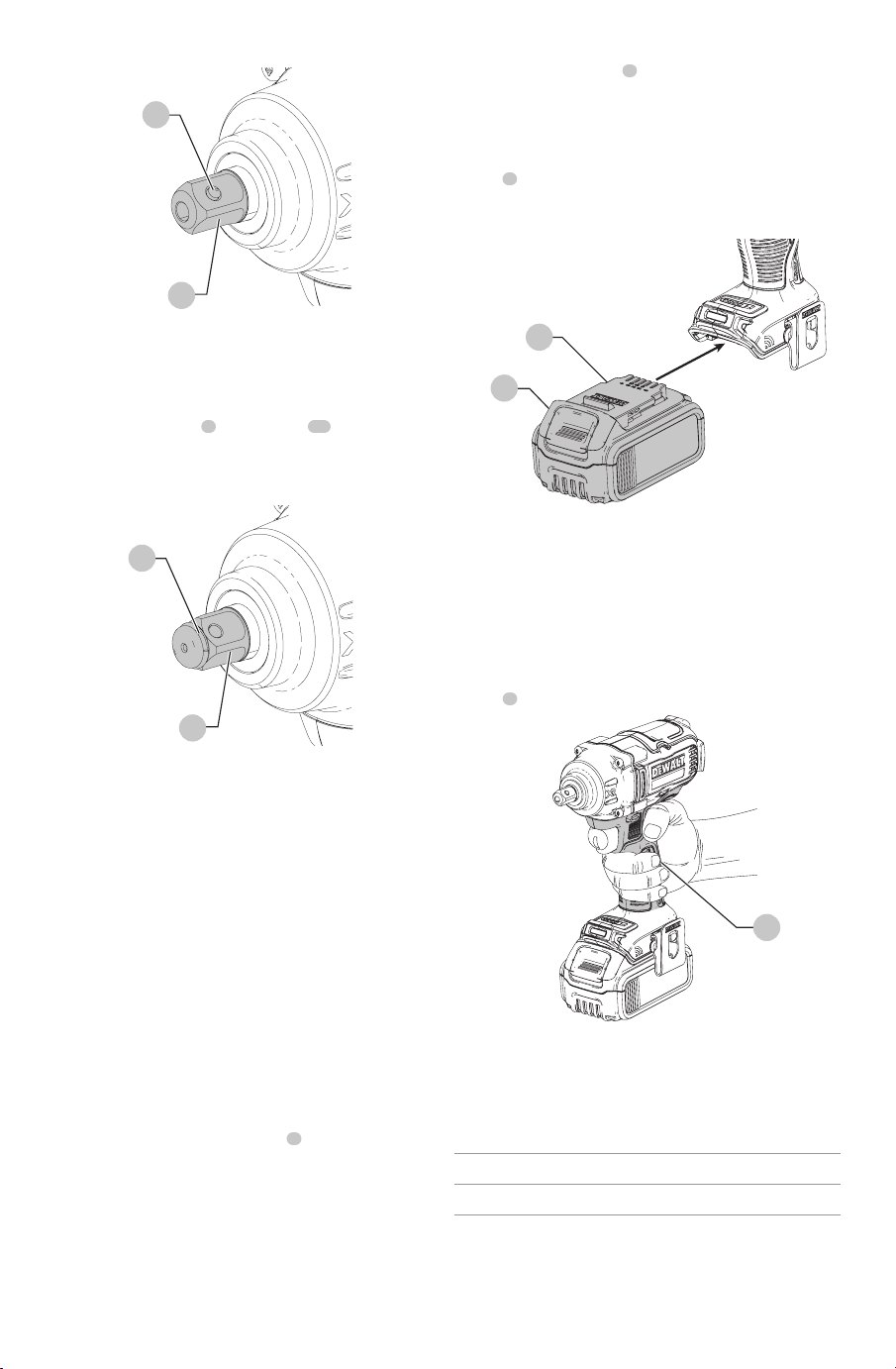
Fig. E
DCF896
9
3
Anvil with Hog Ring (Fig. F)
DCF896H
To install an accessory on the hog ring anvil, firmly push
accessory onto the anvil
3
. The hog ring
10
compresses
to allow the accessory to slide on. After accessory is
installed, the hog ring applies pressure to help provide
accessoryretention.
Fig. F
DCF896h
10
3
To remove an accessory, grasp the accessory and firmly
pull itoff.
nOTE: The thru-hole (Fig.F) allows an O-ring with retaining
pin or a 1-piece retaining pin to be used to help secure
sockets and accessories to thetool.
OPERATION
WARNING: To reduce the risk of serious personal
injury, turn unit off and remove the battery pack
before making any adjustments or removing/
installing attachments or accessories. An
accidental start-up can causeinjury. Exception—Tool
Connect™ functions and mode adjustments require
battery to beinstalled.
NOTICE: Always check the tool configuration prior
to use. If you are unsure of the current configuration,
press the mode selector button
8
(Fig. D) to set the
tool to the Home setting as described on the label and
thismanual.
Installing and Removing the Battery Pack
(Fig. G)
nOTE: For best results, make sure your battery pack is
fullycharged.
To install the battery pack
6
into the tool handle, align the
battery pack with the rails inside the tool’s handle and slide
it into the handle until the battery pack is firmly seated in
the tool and ensure that it does notdisengage.
To remove the battery pack from the tool, press the release
button
5
and firmly pull the battery pack out of the tool
handle. Insert it into the charger as described in the charger
section of thismanual.
Fig. G
5
6
Proper Hand Position (Fig. H)
WARNING: To reduce the risk of serious personal injury,
ALWAYS use proper hand position as shown.
WARNING: To reduce the risk of serious personal
injury, ALWAYS hold securely in anticipation of a
suddenreaction.
Proper hand position requires one hand on the main
handle
4
.
Fig. H
4
Using the Tool
Your impact tool can generate the following maximum
tightening torque values (Speed 3, Speed 2, Speed 1).
Ft.-lbs. nm
Cat # Speed 3/2/1 Speed 3/2/1
DCF896, DCF896H 330/330/150 3960/3960/1800
nOTE: Tool Connect™ custom speed settings will affect the
maximum torque output of the tool. Speeds lower than the
Home setting generally result in lower maximumtorque.
CAUTION: Ensure fastener and/or system will
withstand the level of torque generated by the tool.
Loading ...
Loading ...
Loading ...