m _m_B
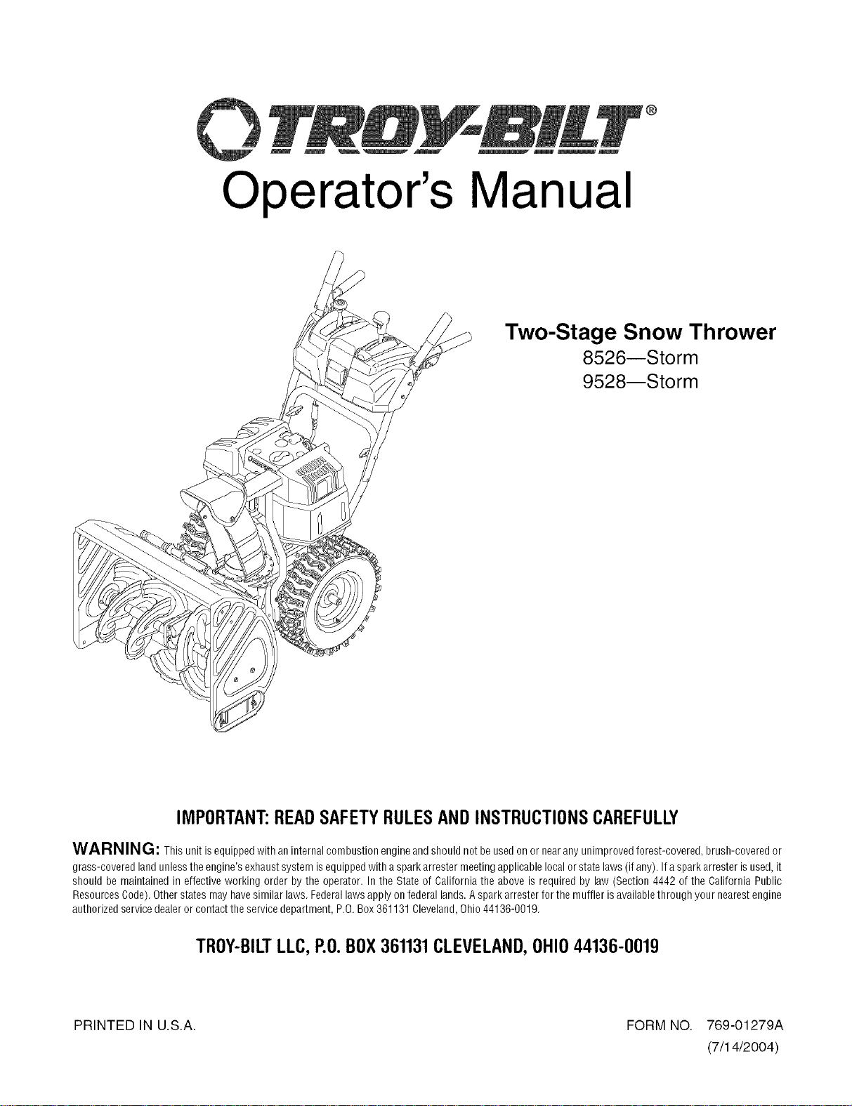
Operator's Manual
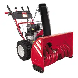
Two-Stage Snow Thrower
8526--Storm
9528--Storm
IMPORTANT:READSAFETYRULESANDINSTRUCTIONSCAREFULLY
WARNING: This unit isequippedwith an internal combustion engineand should not be usedon or nearany unimproved forest-covered, brush-covered or
grass-covered land unless theengine's exhaustsystem isequipped with aspark arrester meeting applicable local or state laws(if any). If aspark arrester isused, it
should be maintained in effective working order by the operator. In the State of California the above is required by law (Section 4442 of the California Public
ResourcesCode). Other states may havesimilar laws. Federallaws apply on federal lands.A spark arrester for the muffler isavailable through your nearest engine
authorized service dealer or contactthe service department, P.0. Box 361131 Cleveland,Ohio44136-0019.
TROY-BILTLLC,P.O.BOX361131CLEVELAND,OHIO44136-0019
PRINTED IN U.S.A. FORM NO. 769-01279A
(7/14/2004)
Content
ImportantSafeOperationPractices
AssemblingYourSnowThrower
KnowYourSnowThrower
OperatingYourSnowThrower
MakingAdjustments
TABLEOFCONTENTS
Page
3
6
8
10
13
Content Page
Maintaining Your Snow Thrower 15
Servicing Your Snow Thrower 15
Troubleshooting 20
Illustrated Parts List 22
Warranty Back Cover
FINDINGMODELNUMBER
This Operator's Manual is an important part of your new rear-tine tiller. It will help you assemble, prepare and
maintain the unit for best performance. Please read and understand what it says.
Before you start assembling your new equipment, please locate the model plate on the equipment
and copy the information from it in the space provided below. A sample model plate is also given below.
You can locate the model plate by standing behind the unit and looking down at rear surface of the frame.
This information will be necessary to use the manufacturer's web site and/or help from the Customer
Support Department or an authorized service dealer.
P. O. BOX 361131
w'ww.troybilt.com CLEVELAND, OH 44136
338-558-7228
1-800-520-5520
Copy the model number here:
Copy the serial number here:
CUSTOMERSUPPORT
Pleasedo NOTreh/m thel/nit totheretailer fromwhereit waspurchased,withoutfirstcontactingCustomerSupport.
If you have difficulty assembling this product or have any questions regarding the controls, operation or
maintenance of this unit, you can seek help from the experts. Choose from the options below:
Engine
Visit troy-bilt.com for many useful suggestions. Click on Customer Support button and you
will get the four options reproduced here. Click on the appropriate button and help is
immediately available.
F_nd Alsswe_s
I QII(+
leel I lli_ iI IIi_ _I {)+,_ AI <I
If you prefer to reach a Customer Support Representative, please call 1(800) 520-5520.
The engine manufacturer is responsible for all engine-related issues with regards to
)erformance, power-rating, specifications, warranty and service. Please refer to the engine
manufacturer's Owner's/Operator's Manual, packed separately with your unit, for more
information.
SECTION1: IMPORTANTSAFEOPERATIONPRACTICES
WARNING: Engine Exhaust, some of its constituents, and certain vehicle components
contain or emit chemicals known to the State of California to cause cancer, birth defects or
other reproductive harm.
DANGER: This machine was built to be operated according to the rules for safe operation in this
manual. As with any type of power equipment, carelessness or error on the part of the operator can
result in serious injury. This machine is capable of amputating hands and feet and throwing objects.
Failure to observe the following safety instructions could result in serious injury or death.
Training
1. Read, understand, and follow all instructions on the
machine and in the manual(s) before attempting to
assemble and operate. Keep this manual in a safe
place for future and regular reference and for
ordering replacement parts.
2. Be familiar with all controls and their proper
operation. Know how to stop the machine and
disengage them quickly.
3. Never allow children under 14 years old to operate
this machine. Children 14 years old and over
should read and understand the operation
instructions and safety rules in this manual and
should be trained and supervised by a parent.
4. Never allow adults to operate this machine without
proper instruction.
5. Thrown objects can cause serious personal injury.
Plan your snow-throwing pattern to avoid discharge
of material toward roads, bystanders and the like.
6. Keep bystanders, helpers, pets and children at
least 75 feet from the machine while it is in
operation. Stop machine if anyone enters the area.
7. Exercise caution to avoid slipping or falling,
especially when operating in reverse.
Preparation
1. Thoroughly inspect the area where the equipment
is to be used. Remove all doormats, newspapers,
sleds, boards, wires and other foreign objects,
which could be tripped over or thrown by the auger/
impeller.
2. Always wear safety glasses or eye shields during
operation and while performing an adjustment or
repair to protect your eyes. Thrown objects which
ricochet can cause serious injury to the eyes.
3. Do not operate without wearing adequate winter
outer garments. Do not wear jewelry, long scarves
or other loose clothing, which could become
entangled in moving parts. Wear footwear which
will improve footing on slippery surfaces.
4.
5.
6.
7.
8.
9.
Use a grounded three-wire extension cord and
receptacle for all units with electric start engines.
Adjust collector housing height to clear gravel or
crushed rock surfaces.
Disengage all control levers beforestarting the engine.
Never attempt to make any adjustments while
engine is running, except where specifically
recommended in the operator's manual.
Let engine and machine adjust to outdoor
temperature before starting to clear snow.
To avoid personal injury or property damage use
extreme care in handling gasoline. Gasoline is
extremely flammable and the vapors are explosive.
Serious personal injury can occur when gasoline is
spilled on yourself or your clothes, which can ignite.
Wash your skin and change clothes immediately.
a. Use only an approved gasoline container.
b. Extinguish all cigarettes, cigars, pipes and
other sources of ignition.
c. Never fuel machine indoors.
d. Never remove gas cap or add fuel while the
engine is hot or running.
e. Allow engine to cool at least two minutes
before refueling.
f. Never over fill fuel tank. Fill tank to no more
than Y2inch below bottom of filler neck to
provide space for fuel expansion.
g. Replace gasoline cap and tighten securely.
h. If gasoline is spilled, wipe it off the engine
and equipment. Move machine to another
area. Wait 5 minutes before starting the
engine.
i. Never store the machine or fuel container
inside where there is an open flame, spark or
pilot light (e.g. furnace, water heater, space
heater, clothes dryer etc.).
j. Allow machine to cool at least 5 minutes
before storing.

Operation
1. Donotputhandsorfeetnearrotatingparts,in the
auger/impeller housing or chute assembly. Contact
with the rotating parts can amputate hands and
feet.
2. The auger/impeller control lever is a safety device.
Never bypass its operation. Doing so makes the
machine unsafe and may cause personal injury.
3. The control levers must operate easily in both
directions and automatically return to the
disengaged position when released.
4. Never operate with a missing or damaged chute
assembly. Keep all safety devices in place and
working.
5. Never run an engine indoors or in a poorly
ventilated area. Engine exhaust contains carbon
monoxide, an odorless and deadly gas.
6. Do not operate machine while under the influence
of alcohol or drugs.
7. Muffler and engine become hot and can cause a
burn. Do not touch.
8. Exercise extreme caution when operating on or
crossing gravel surfaces. Stay alert for hidden
hazards or traffic.
9. Exercise caution when changing direction and
while operating on slopes.
10. Plan your snow-throwing pattern to avoid discharge
towards windows, walls, cars etc. Thus, avoiding
possible property damage or personal injury
caused by a ricochet.
11. Never direct discharge at children, bystanders and
pets or allow anyone in front of the machine.
12. Do not overload machine capacity by attempting to
clear snow at too fast of a rate.
13. Never operate this machine without good visibility
or light. Always be sure of your footing and keep a
firm hold on the handles. Walk, never run.
14. Disengage power to the auger/impeller when
transporting or not in use.
15. Never operate machine at high transport speeds on
slippery surfaces. Look down and behind and use
care when backing up.
16. If the machine should start to vibrate abnormally,
stop the engine, disconnect the spark plug wire and
ground it against the engine. Inspect thoroughly for
damage. Repair any damage before starting and
operating.
17. Disengage all control levers and stop engine before
you leave the operating position (behind the
handles). Wait until the auger/impeller comes to a
complete stop before unclogging the chute
assembly, making any adjustments, or inspections.
18. Never put your hand in the discharge or collector
openings. Always use the clean-out tool provided to
unclog the discharge opening. Do not unclog chute
assembly while engine is running. Shut off engine
and remain behind handles until all moving parts
have stopped before unclogging.
19. Use only attachments and accessories approved
by the manufacturer (e.g. wheel weights, tire
chains, cabs etc.).
20. If situations occur which are not covered in this
manual, use care and good judgment. Contact your
dealer or call (800) 520-5520 for assistance and the
name of your nearest servicing dealer.
Maintenance&Storage
1. Never tamper with safety devices. Check their
proper operation regularly. Refer to the
maintenance and adjustment sections of this
manual.
2. Before cleaning, repairing, or inspecting machine
disengage all control levers and stop the engine.
Wait until the auger/impeller come to a complete
stop. Disconnect the spark plug wire and ground
against the engine to prevent unintended starting.
3. Check bolts and screws for proper tightness at
frequent intervals to keep the machine in safe
working condition. Also, visually inspect machine
for any damage.
4. Do not change the engine governor setting or over-
speed the engine. The governor controls the
maximum safe operating speed of the engine.
5. Snow thrower shave plates and skid shoes are
subject to wear and damage. For your safety
protection, frequently check all components and
replace with original equipment manufacturer's
(OEM) parts only. "Use of parts which do not meet
the original equipment specifications may lead to
improper performance and compromise safety!"
6. Check controls periodically to verify they engage
and disengage properly and adjust, if necessary.
Refer to the adjustment section in this operator's
manual for instructions.
7. Maintain or replace safety and instruction labels, as
necessary.
8. Observe proper disposal laws and regulations for
gas, oil, etc. to protect the environment.
9. Prior to storing, run machine afew minutes to clear
snow from machine and prevent freeze up of auger/
impeller.
10. Never store the machine or fuel container inside
where there is an open flame, spark or pilot light
such as a water heater, furnace, clothes dryer etc.
11. Always refer to the operator's manual for proper
instructions on off-season storage.
YOURRESPONSIBILITY
Restrict the use of this power machine to persons who read, understand and follow the warnings and instructions in
this manual and on the machine.
Donotmodifyengine
To avoid serious injury or death, do not modify engine
in any way. Tampering with the governor setting can
lead to a runaway engine and cause it to operate at
unsafe speeds. Never tamper with factory setting of
engine governor.
Notice regarding Emissions
Engines which are certified to comply with California
and federal EPA emission regulations for SORE (Small
Off Road Equipment) are certified to operate on regular
unleaded gasoline, and may include the following
emission control systems: Engine Modification (EM)
and Three Way Catalyst (TWC) if so equipped.
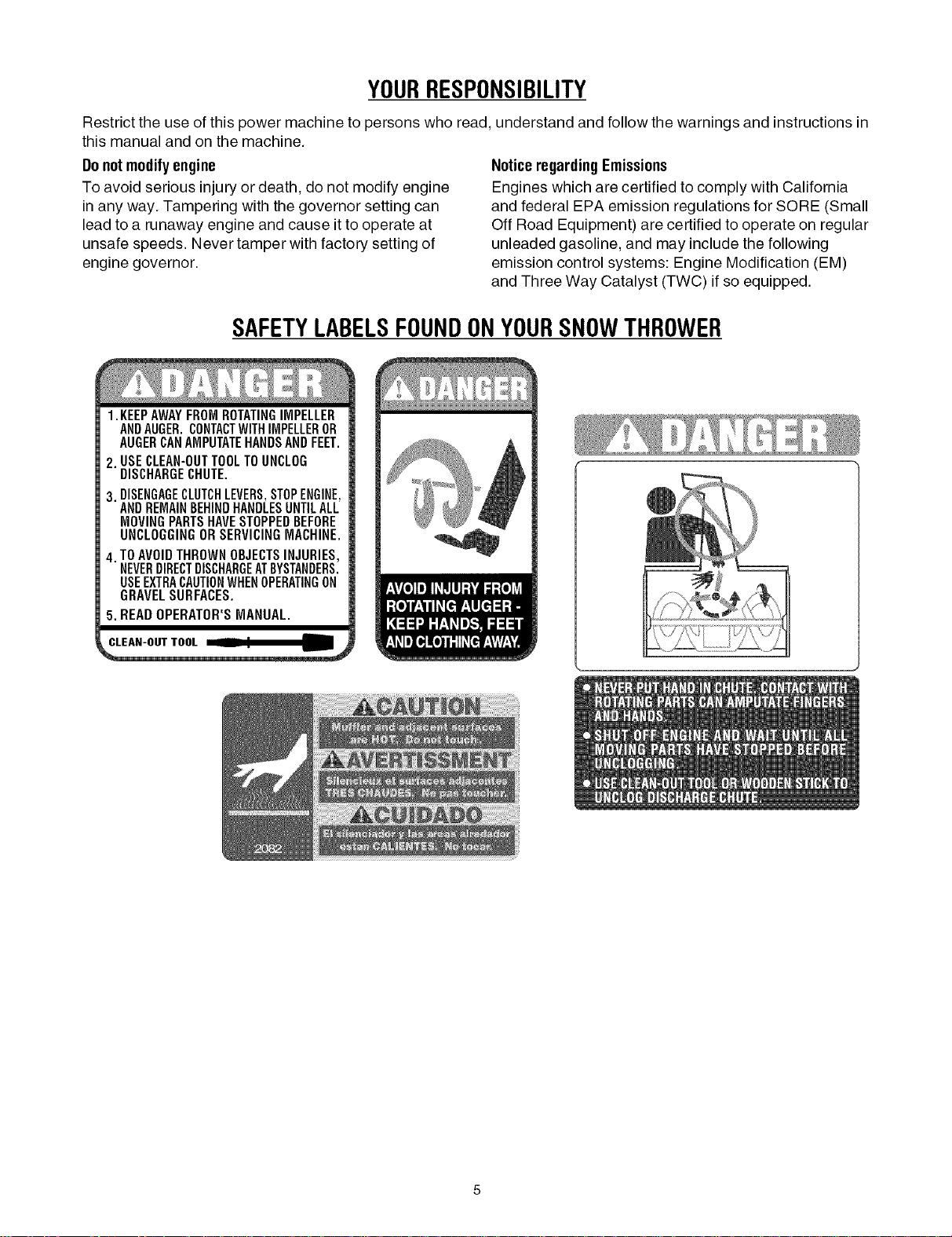
SAFETYLABELSFOUNDONYOURSNOWTHROWER
1.KEEPAWAYFROMROTATINGIMPELLER
ANDAUGER.CONTACTWITHIMPELLEROR
AUGERCANAMPUTATEHANDSANDFEET.
2. USECLEAN-OUTTOOLTOUNCLOG
DISCHARGECHUTE.
3. DISENGAGECLUTCHLEVERS,STOPENGINE,
ANDREMAINBEHINDHANDLESUNTILALL
MOVINGPARTSHAVESTOPPEDBEFORE
UNCLOGGINGORSERVICINGMACHINE.
4. TOAVOIDTHROWNOBJECTSINJURIES,
NEVERDIRECTDISCHARGEATBYSTANDERS.
USEEXTRACAUTIONWHENOPERATINGON
GRAVELSURFACES.
5. READOPERATOR'SMANUAL.
SECTION2: ASSEMBLINGYOURSNOWTHROWER
NOTE: References to right or left side of the snow
thrower are determined from behind the unit in the
operating position (standing directly behind the snow
thrower, facing the handle panel).
IMPORTANT:Two replacement auger shear pins are
included with this manual (or stowed in the plastic
handle panel). Refer to Augerson page 19 for more
information regarding shear pin replacement.
,_ CAUTION: Prior to operating your snow
thrower, refer to AugerControlTeston page 11.
Read and follow all instructions carefully and
perform all adjustments to verify your snow
thrower is operating safely and properly.
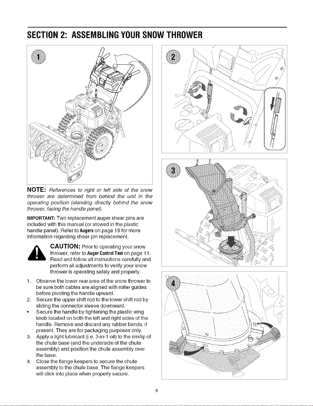
1. Observe the lower rear area of the snow thrower to
be sure both cables are aligned with roller guides
before pivoting the handle upward.
2. Secure the upper shift rod to the lower shift rod by
sliding the connector sleeve downward.
•Secure the handle by tightening the plastic wing
knob located on both the left and right sides of the
handle. Remove and discard any rubber bands, if
present. They are for packaging purposes only.
3. Apply a light lubricant (i.e. 3-in-1 oil) to the rim/lip of
the chute base (and the underside of the chute
assembly) and position the chute assembly over
the base.
4. Close the flange keepers to secure the chute
assembly to the chute base. The flange keepers
will click into place when properly secure.
NOTE: If the flange keepers will not easily click into
place, use the palm of your hand to apply swift, firm
pressure to the back of each.
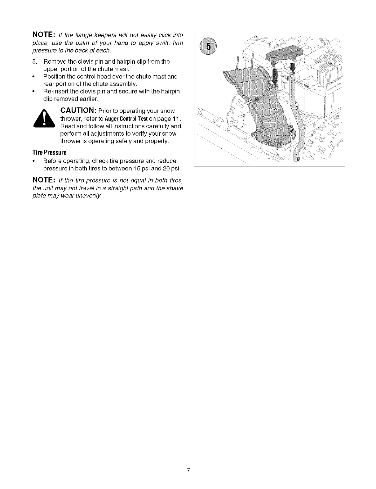
5. Remove the clevis pin and hairpin clip from the
upper portion of the chute mast.
• Position the control head over the chute mast and
rear portion of the chute assembly.
• Re-insert the clevis pin and secure with the hairpin
clip removed earlier.
,_ CAUTION: Prior to operating your snow
thrower, refer to AugerControlTeston page 11.
Read and follow all instructions carefully and
perform all adjustments to verify your snow
thrower is operating safely and properly.
Tire Pressure
• Before operating, check tire pressure and reduce
pressure in both tires to between 15 psi and 20 psi.
NOTE: If the tire pressure is not equal in both tires,
the unit may not travel in a straight path and the shave
plate may wear unevenly.
©
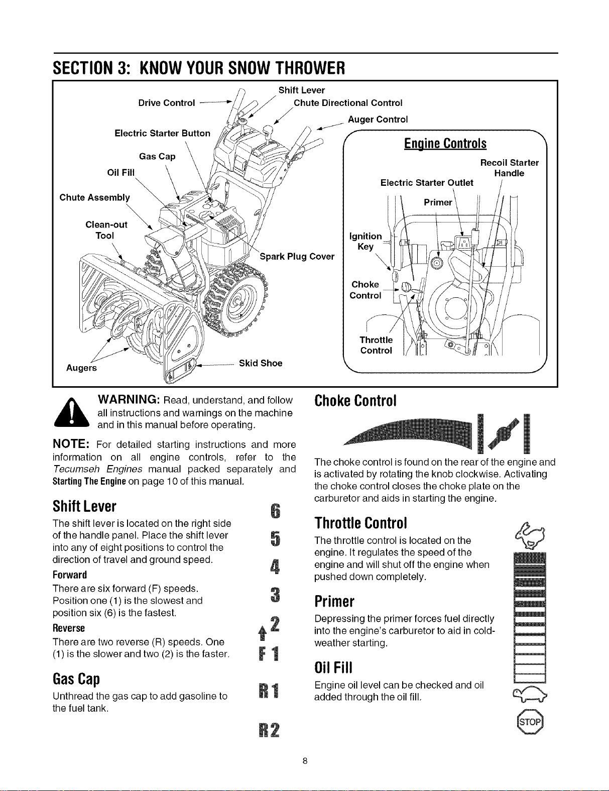
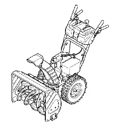
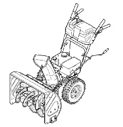
SECTION3: KNOWYOURSNOWTHROWER
Drive Control
Electric Starter Button
Gas Cap
Oil Fill
Chute Assembly
Clean-out_
Tool
Shift Lever
Chute Directional Control
Auger Control
fEngineControls
Electric Starter Outlet
Ignition
Key
Spark Plug Cover
Choke
Control
Recoil Starter
Handle
Augers Skid Shoe
Throttle
Control
,J
,_ WARNING: Read, understand, and follow
all instructions and warnings on the machine
and in this manual before operating.
NOTE: For detailed starting instructions and more
information on all engine controls, refer to the
Tecumseh Engines manual packed separately and
StartingTheEngineon page 10 of this manual.
ShiftLever 6
The shift lever is located on the right side
of the handle panel. Place the shift lever
into any of eight positions to control the v
direction of travel and ground speed, j
Ferward
There are six forward (F) speeds.
Position one (1) is the slowest and U
position six (6) is the fastest.
Reverse _ 2
There are two reverse (R) speeds. One
(1) is the slower and two (2) is the faster. F 1
GasCap
Unthread the gas cap to add gasoline to
the fuel tank. R1
B2
ChokeControl ii1
The choke control isfound on the rear of the engine and
is activated by rotating the knob clockwise. Activating
the choke control closes the choke plate on the
carburetor and aids in starting the engine.
ThrottleControl
The throttle control islocated on the
engine. It regulates the speed of the
engine and willshut off the engine when
pushed down completely.
Primer
Depressing the primer forces fuel directly
into the engine's carburetor to aid in cold-
weather starting.
0il Fill
Engine oil level can be checked and oil
added through the oil fill.
©
m
/
@
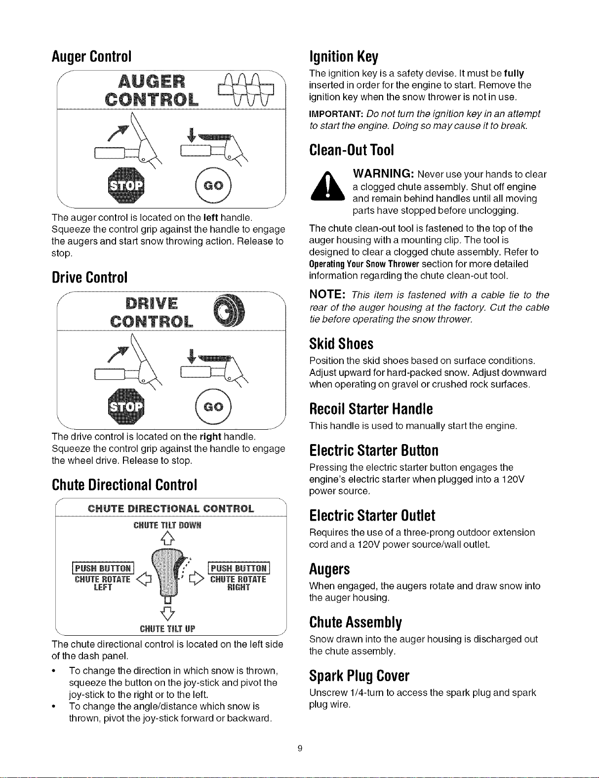
AugerControl
f
The auger control is located on the left handle.
Squeeze the control grip against the handle to engage
the augers and start snow throwing action. Release to
stop.
DriveControl
f
The drive control is located on the right handle.
Squeeze the control grip against the handle to engage
the wheel drive. Release to stop.
ChuteDirectionalControl
fCHUTE DIRECTIONAL CONTROL \
CHUTETiLT#SWN
[PUSH BUTTON1
CHUTEROTME
RIGHT
©
CHUTETiLTUP
The chute directional control islocated on the left side
of the dash panel.
•To change the direction in which snow is thrown,
squeeze the button on the joy-stick and pivot the
joy-stick to the right or to the left.
• To change the angle/distance which snow is
thrown, pivot the joy-stick forward or backward.
IgnitionKey
The ignition key is a safety devise. It must be fully
inserted in order for the engine to start. Remove the
ignition key when the snow thrower is not in use.
IMPORTANT:Do not turn the ignition key in an attempt
to start the engine. Doing so may cause it to break.
Clean-OutTool
WARNING: Never use your hands to clear
a clogged chute assembly. Shut off engine
and remain behind handles until all moving
parts have stopped before unclogging.
The chute clean-out tool is fastened to the top of the
auger housing with a mounting clip. The tool is
designed to clear a clogged chute assembly. Refer to
OperatingYeurSnewThrewer section for more detailed
information regarding the chute clean-out tool.
NOTE: This item is fastened with a cable fie to the
rear of the auger housing at the factory. Cut the cable
tie before operating the snow thrower.
SkidShoes
Position the skid shoes based on surface conditions.
Adjust upward for hard-packed snow. Adjust downward
when operating on gravel or crushed rock surfaces.
RecoilStarterHandle
This handle is used to manually start the engine.
ElectricStarterButton
Pressing the electric starter button engages the
engine's electric starter when plugged into a 120V
power source.
ElectricStarterOutlet
Requires the use of a three-prong outdoor extension
cord and a 120V power source/wall outlet.
Augers
When engaged, the augers rotate and draw snow into
the auger housing.
ChuteAssembly
Snow drawn into the auger housing is discharged out
the chute assembly.
SparkPlugCover
Unscrew 1/4-turn to access the spark plug and spark
plug wire.
SECTION4: OPERATINGYOURSNOWTHROWER
BeforeStarting
,_ WARNING: Read, understand, and followall instructions and warnings on the machine
and in this manual before operating.
Gas& OilFill-Up
Service the engine with gasoline and oil as instructed in
the Tecumseh Engines manual packed separately with
your snow thrower. Read instructions carefully.
,_ WARNING: Use extreme care when
handling gasoline. Gasoline is extremely
flammable and the vapors are explosive.
Never fuel the machine indoors or while the
engine is hot or running. Extinguish cigarettes,
cigars, pipes and other sources of ignition.
• A small plastic cup may be located inside the fuel fill
opening beneath the gas cap. Remove and discard
this cup before filling up the tank.
StartingTheEngine
• Attach spark plug wire to spark plug. Make certain
the metal loop on the end of the spark plug wire
(inside the rubber boot) is fastened securely over
the metal tip on the spark plug.
• Make certain both the auger control and drive
control are in the disengaged (released) position.
• Move throttle control up to FAST position. Insert
ignition key into slot. Make sure it snaps into place.
Do not attempt to turn the key.
NOTE: The engine cannot start unless the key is
inserted into ignition switch.
Electric Starter
• Determine that your home's wiring is a three-wire
grounded system. Ask a licensed electrician if you
are not certain.
CAUTION: Ifyour home's wiring system
is not a three-wire grounded system, do
not use this electric starter under any
conditions.
WARNING: The optional electric starter is
equipped with a grounded three-wire power
cord and plug, and is designed to operate on
120 volt AC household current. It must be
used with a properly grounded three-prong
receptacle at all times to avoid the possibility
of electric shock. Follow all instructions
carefully prior to operating the electric starter.
WARNING: If your home electrical
system is grounded, but a three-hole
receptacle is not available, do not use your
snow thrower's electric starter.
If you have a grounded three-prong receptacle,
proceed as follows:
• Plug the extension cord into the outlet located on
the engine's surface. Plug the other end of
extension cord into a three-prong 120-volt,
grounded, AC outlet in a well-ventilated area.
• Rotate choke control to FULL choke position (cold
engine start).
NOTE: If the engine is already warm, place choke
control in the OFF position instead of FULL.
• Push the primer two or three times for cold engine
start, making sure to cover vent hole in the center of
the primer when pushing.
NOTE: DO NOT use primer to restart a warm engine
after a short shutdown.
• Push starter button to start engine.
• Once the engine starts, immediately release starter
button.
• As the engine warms, slowly rotate the choke
control to the OFF position. If the engine falters,
quickly rotate the choke control back to FULL and
then slowly into the OFF position again.
• When disconnecting the extension cord, always
unplug the end at the three-prong wall outlet before
unplugging the opposite end from the snow
thrower.
RecoilStarter
• Rotate choke control to FULL choke position (cold
engine start).
NOTE: If the engine is already warm, place choke
control in the OFF position instead of FULL.
• Push the primer two or three times for cold engine
start, making sure to cover vent hole in the center of
the primer when pushing.
NOTE: DO NOT use primer to restart a warm engine
after a short shutdown.
NOTE: Additional priming may be necessary if the
temperature is below 15° Fahrenheit.
Grasp the recoil starter handle and slowly pull the
rope out. At the point where it becomes slightly
harder to pull the rope, slowly allow the rope to
recoil.
10
• Pull the starter handle with a firm, rapid stroke.
IMPORTANT: Do not release the handle and allow it to
snap back. Keep a firm hold on the starter handle and
allow it to slowly recoil.
• As the engine warms, slowly rotate the choke
control to the OFF position. If the engine falters,
quickly rotate the choke control back to the FULL
position and then slowly into the OFF position
again.
StoppingTheEngine
• Run engine for a few minutes before stopping to
help dry off any moisture on the engine.
• To help prevent possible starter freeze-up, proceed
as follows:
ElectricStarter (on models so equipped)
1. Connect extension cord to the electric starter outlet
on the engine, then to 120 volt AC outlet.
2. With the engine running, push the starter button
and allow the starter for spin for several seconds.
The noise made by the starter is normal. The
engine's starter is not being harmed.
3. When disconnecting the extension cord, always
unplug the end at the three-prong wall outlet before
unplugging the opposite end from the snow
thrower.
4. Move throttle control to STOP position.
5. Remove the ignition key.
6. Wipe all snow and moisture from the area around
the engine as well as the area in and around the
drive control and auger control. Also, engage and
release both controls several times.
NOTE: Keep the key in a safe place. The engine
cannot start without the ignition key.
RecoilStarter
1. With engine running, pull starter rope with a rapid,
continuous full arm stroke three or four times.
Pulling the starter rope will produce a loud
clattering sound, which is not harmful to engine.
2. Move throttle control to STOP position.
3. Remove the ignition key.
NOTE: Keep the key in a safe place. The engine
cannot start without the ignition key.
4. Wipe all snow and moisture from the area around
the engine as well as the area in and around the
drive control and auger control. Also, engage and
release both controls several times.
ToEngageDrive
• With the throttle control in the Fast (rabbit) position,
move shift lever into one of the six forward (F)
positions or two reverse (R) positions. Select a
speed appropriate for the snow conditions and a
pace you're comfortable with.
IMPORTANT:Use the slower speeds until you are
comfortable and familiar with the operation of the snow
thrower.
• Squeeze the drive control against the handle the
snow thrower will move. Release it and drive
motion will stop.
IMPORTANT:NEVER reposition the shift lever (change
speeds or direction of travel) without first releasing the
drive control and bringing the snow thrower to a
complete stop. Doing so will result in premature wear to
the snow thrower's drive system.
ToEngageAugers
• To engage the augers and start throwing snow,
squeeze the auger control against the left handle.
Release to stop the augers.
AugerControl Test
IMPORTANT:Perform the following test before
operating your snow thrower for the first time and at the
start of each winter season.
Check the adjustment of the auger control as follows:
• When the auger control is released and in the
disengaged "up" position, the cable should have
very little slack. It should NOT be tight.
• In a well-ventilated area, start the snow thrower
engine as instructed earlier in this section under the
heading StartingtheEngine.Make sure the throttle is
set in the FAST position.
• While standing in the operator's position (behind
the snow thrower), engage the auger.
• Allow the auger to remain engaged for
approximately ten (10) seconds before releasing
the auger control. Repeat this several times.
• With the throttle control in the FAST (rabbit)
position and the auger control in the disengaged
"up" position, walk to the front of the machine.
• Confirm that the auger has completely stopped
rotating and shows NO signs of motion.
IMPORTANT:If the auger shows ANY signs of rotating,
immediately return to the operator's position and shut
off the engine. Wait for ALL moving parts to stop before
re-adjusting the auger control.
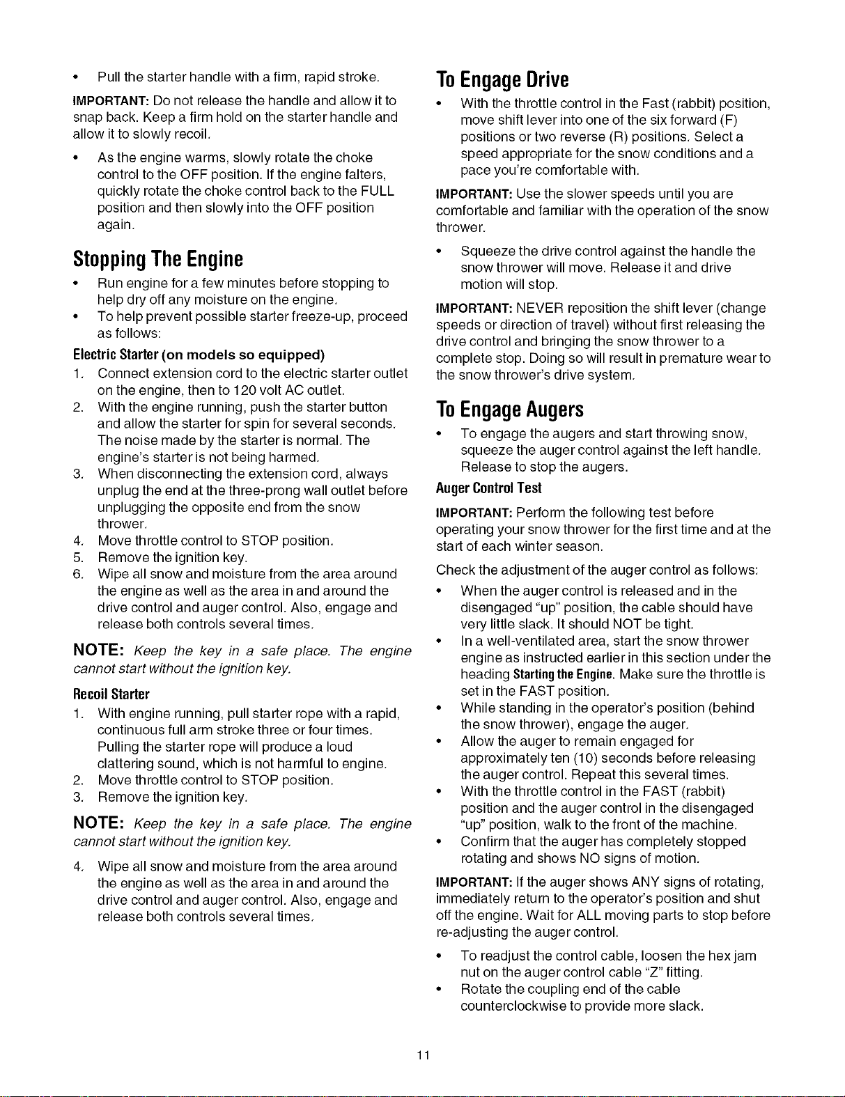
• To readjust the control cable, loosen the hexjam
nut on the auger control cable "Z" fitting.
• Rotate the coupling end of the cable
counterclockwise to provide more slack.
11
• Retighten the hex jam nut. See Figure 1.
• Repeat Auger Control Test to verify proper
adjustment has been achieved.
\
Figure 1
ChuteClean-OutTool
The chute clean-out tool is conveniently fastened to the
rear of the auger housing with a mounting clip. Should
snow and ice become lodged in the chute assembly
during operation, proceed as follows to safely clean the
chute assembly and chute opening:
• Release both the Auger Control and the Drive
Control.
• Stop the engine by removing the ignition key.
• Remove the clean-out tool from the clip which
secures it to the rear of the auger housing.
• Use the shovel-shaped end of the clean-out tool to
dislodge and scoop any snow and ice which has
formed in and near the chute assembly.
,_ WARNING: Never use your hands to clean
snow and ice from the chute assembly or
auger housing
• Refasten the clean-out tool to the mounting clip on
the rear of the auger housing, reinsert the ignition
key and start the snow thrower's engine.
While standing in the operator's position (behind
the snow thrower), engage the auger control for a
few seconds to clear any remaining snow and ice
from the chute assembly.
Drive/AugerLock
The drive/auger lock allows the user to operate the
snow thrower with one hand, leaving the left hand free
to operate the chute directional control.
• Engage both the Auger Control and the Drive
Control at the same time.
• Release the Auger Control and it will remain
engaged until the Drive Control is also released.
OperatingTips
NOTE: Allow the engine to warm up for a few minutes
after starting. The engine will not develop full power
until it reaches operating temperature.
_, WARNING: The muffler, engine and
surrounding areas become hot and can
cause a burn. Do not touch.
• Discharge snow downwind whenever possible.
• Slightly overlap each previous swath.
• Set the skid shoes 1/4" below the scraper bar for
normal usage. The skid shoes may be adjusted
upward for hard-packed snow. Adjust downward
when using on gravel or crushed rock.
• Avoid possible starter freeze-up. Clean the snow
thrower thoroughly after each use.
12
SECTION5: MAKINGADJUSTMENTS
WARNING: Never attempt to make anyadjustments while the engine is running,
except where specified in operator's manual.
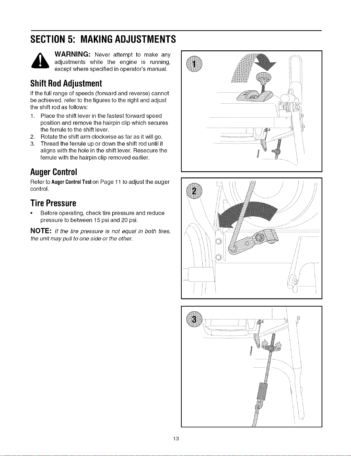
ShiftRodAdjustment
If the full range of speeds (forward and reverse) cannot
be achieved, refer to the figures to the right and adjust
the shift rod as follows:
1. Place the shift lever in the fastest forward speed
position and remove the hairpin clip which secures
the ferrule to the shift lever.
2. Rotate the shift arm clockwise as far as it will go.
3. Thread the ferrule up or down the shift rod until it
aligns with the hole in the shift lever. Resecure the
ferrule with the hairpin clip removed earlier.
AugerControl
Refer to AugerControlTeston Page 11 to adjust the auger
control.
TirePressure
• Before operating, check tire pressure and reduce
pressure to between 15 psi and 20 psi.
NOTE: If the tire pressure is not equal in both tires,
the unit may pull to one side or the other.
13
DriveControl
When the drive control is released and in the
disengaged "up" position, the cable should have very
little slack. It should NOT be tight.
Check the adjustment of the drive control as follows:
1. With the drive control released, push the snow
thrower gently forward. The unit should roll freely.
2. Engage the drive control and gently attempt to push
the snow thrower forward. The wheels should not
turn. The unit should not roll freely.
3. With the drive control released, move the shift lever
back and forth between the R2 position and the F6
position several times. There should be no
resistance in the shift lever.
If any of the above tests failed, the drive cable is in need
of adjustment, refer to the figure at the right and
proceed as follows:
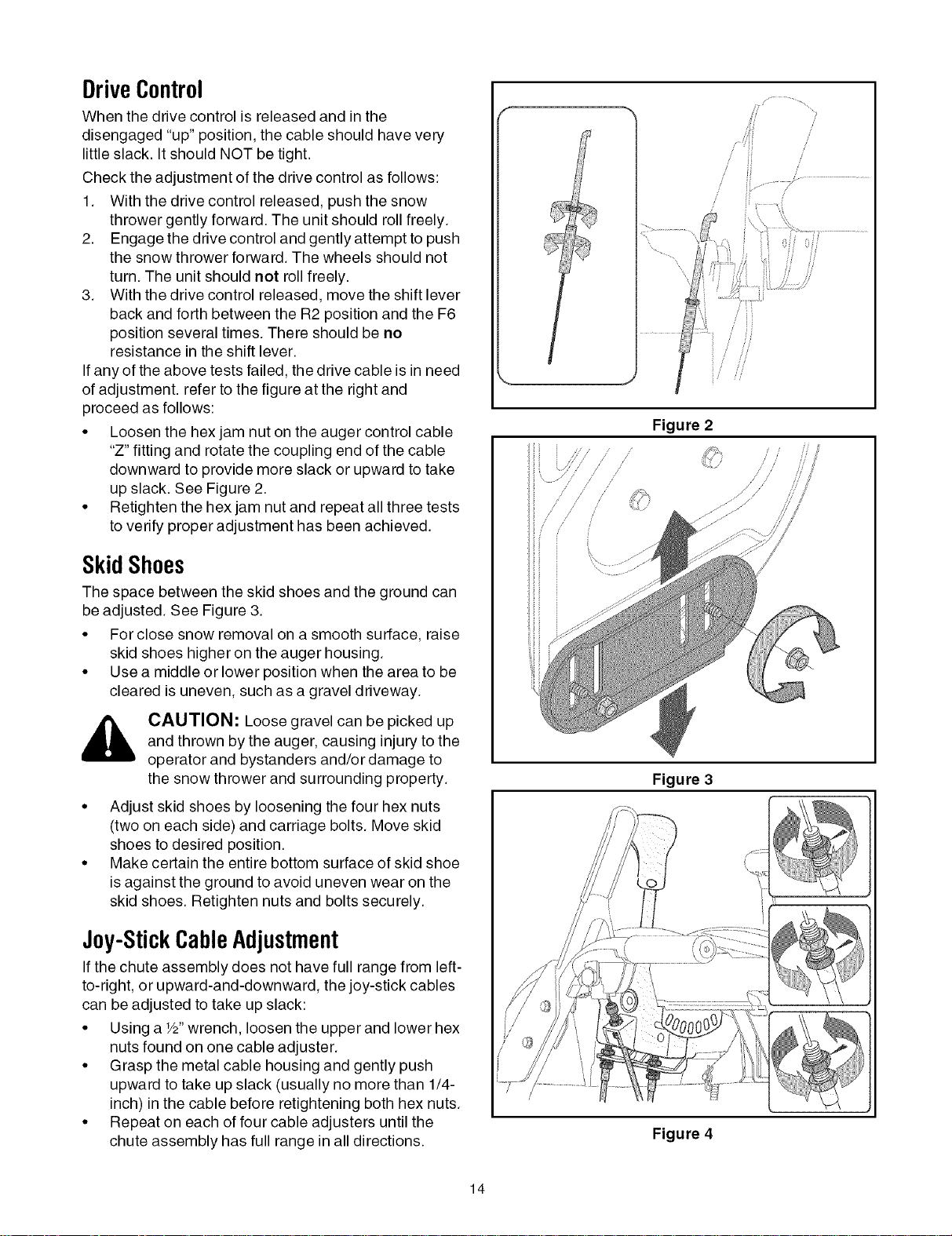
• Loosen the hex jam nut on the auger control cable
"Z" fitting and rotate the coupling end of the cable
downward to provide more slack or upward to take
up slack. See Figure 2.
• Retighten the hex jam nut and repeat all three tests
to verify proper adjustment has been achieved.
SkidShoes
The space between the skid shoes and the ground can
be adjusted. See Figure 3.
• For close snow removal on a smooth surface, raise
skid shoes higher on the auger housing.
• Use a middle or lower position when the area to be
cleared is uneven, such as a gravel driveway.
CAUTION: Loose gravel can be picked up
and thrown by the auger, causing injury to the
operator and bystanders and/or damage to
the snow thrower and surrounding property.
• Adjust skid shoes by loosening the four hex nuts
(two on each side) and carriage bolts. Move skid
shoes to desired position.
• Make certain the entire bottom surface of skid shoe
is against the ground to avoid uneven wear on the
skid shoes. Retighten nuts and bolts securely.
Joy-StickCableAdjustment
If the chute assembly does not have full range from left-
to-right, or upward-and-downward, the joy-stick cables
can be adjusted to take up slack:
• Using a W' wrench, loosen the upper and lower hex
nuts found on one cable adjuster.
• Grasp the metal cable housing and gently push
upward to take up slack (usually no more than 1/4-
inch) in the cable before retightening both hex nuts.
• Repeat on each of four cable adjusters until the
chute assembly has full range in all directions.
/
/
/
/
Figure 2
/
/
Figure 3
Figure 4
14
SECTION6: MAINTAININGANDSERVICINGYOURSNOWTHROWER
WARNING: Before lubricating, repairing, or
inspecting, disengage all controls and stop
engine. Wait until all moving parts have come
to a complete stop.
Engine
Refer to the separate TecumsehEngines manual
packed with your unit for all engine maintenance.
Lubrication
Engine
Refer to the separate Tecumseh Engines manual
packed with your unit for all engine lubrication
instructions.
GearShaft
The gear (hex) shaft should be lubricated at least once
a season or after every 25 hours of operation.
• Remove the lower frame cover by removing the two
screws which secure it.
• Apply a light coating of an all-weather multi-
purpose grease to the hex shaft. See Figure 5.
Figure 5
IMPORTANT:Keep lubricant off the friction wheel and
drive plate.
Wheels
• At least once a season, remove both wheels. Clean
and coat the axles with a multipurpose automotive
grease before reinstalling wheels.
ChuteDirectionalControl
• Once a season, the joystick should be lubricated
with petroleum jelly, linseed oil, mineral oil, paraffin
wax or 3-in-1 oil.
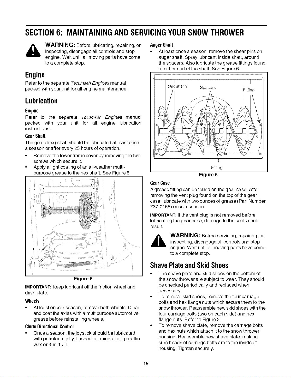
AugerShaft
• At least once a season, remove the shear pins on
auger shaft. Spray lubricant inside shaft, around
the spacers. Also lubricate the grease fittings found
at either end of the shaft. See Figure 6.
-m T
Shear Pin Spacers Fitting
Fitting
Figure 6
GearCase
A grease fitting can be found on the gear case. After
removing the vent plug found on the top of the gear
case, lubricate with two ounces of grease (Part Number
737-0168) once a season.
IMPORTANT:If the vent plug is not removed before
lubricating the gear case, damage to the seals could
result.
WARNING: Before servicing, repairing, or
inspecting, disengage all controls and stop
engine. Wait until all moving parts have come
to a complete stop.
ShavePlateandSkid Shoes
• The shave plate and skid shoes on the bottom of
the snow thrower are subject to wear. They should
be checked periodically and replaced when
necessary.
• To remove skid shoes, remove the four carriage
bolts and hex flange nuts which secure them to the
snow thrower. Reassemble new skid shoes with the
four carriage bolts (two on each side) and hex
flange nuts. Refer to Figure 3.
• To remove shave plate, remove the carriage bolts
and hex nuts which attach it to the snow thrower
housing. Reassemble new shave plate, making
sure heads of carriage bolts are to the inside of
housing. Tighten securely.
15
/
/
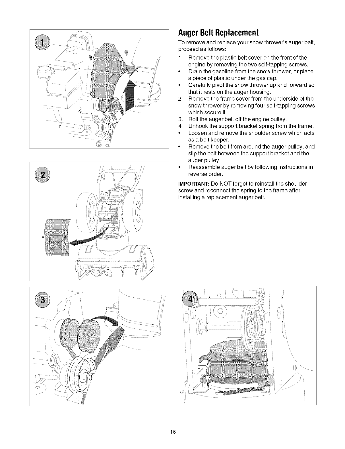
AugerBeltReplacement
To remove and replace your snow thrower's auger belt,
proceed as follows:
1. Remove the plastic belt cover on the front of the
engine by removing the two self-tapping screws.
•Drain the gasoline from the snow thrower, or place
a piece of plastic under the gas cap.
• Carefully pivot the snow thrower up and forward so
that it rests on the auger housing.
2. Remove the frame cover from the underside of the
snow thrower by removing four self-tapping screws
which secure it.
3. Roll the auger belt off the engine pulley.
4. Unhook the support bracket spring from the frame.
• Loosen and remove the shoulder screw which acts
as a belt keeper.
• Remove the belt from around the auger pulley, and
slip the belt between the support bracket and the
auger pulley
• Reassemble auger belt by following instructions in
reverse order.
IMPORTANT: Do NOT forget to reinstall the shoulder
screw and reconnect the spring to the frame after
installing a replacement auger belt.
.......... t
............ !/
_ %.
16
/
/
/
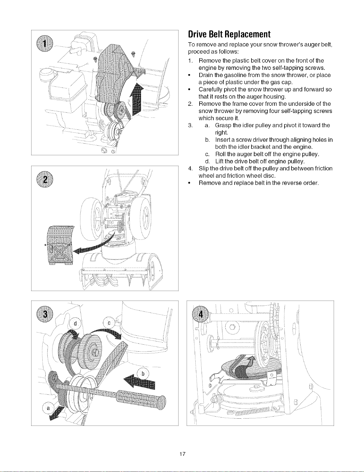
DriveBeltReplacement
To remove and replace your snow thrower's auger belt,
proceed as follows:
1. Remove the plastic belt cover on the front of the
engine by removing the two self-tapping screws.
•Drain the gasoline from the snow thrower, or place
a piece of plastic under the gas cap.
• Carefully pivot the snow thrower up and forward so
that it rests on the auger housing.
2. Remove the frame cover from the underside of the
snow thrower by removing four self-tapping screws
which secure it.
3. a. Grasp the idler pulley and pivot it toward the
right.
b. Insert a screw driver through aligning holes in
both the idler bracket and the engine.
c. Roll the auger belt off the engine pulley.
d. Lift the drive belt off engine pulley.
4. Slip the drive belt off the pulley and between friction
wheel and friction wheel disc.
• Remove and replace belt in the reverse order.
ijj • •-. -
17
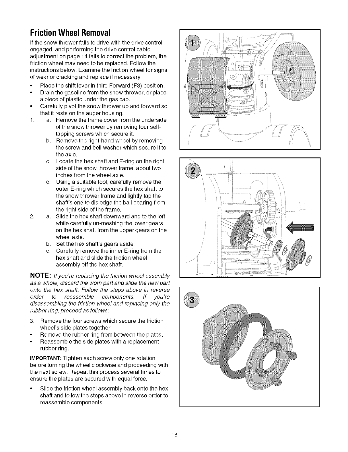
FrictionWheelRemoval
If the snow thrower fails to drive with the drive control
engaged, and performing the drive control cable
adjustment on page 14 fails to correct the problem, the
friction wheel may need to be replaced. Follow the
instructions below. Examine the friction wheel for signs
of wear or cracking and replace if necessary
• Place the shift lever in third Forward (F3) position.
• Drain the gasoline from the snow thrower, or place
a piece of plastic under the gas cap.
• Carefully pivot the snow thrower up and forward so
that it rests on the auger housing.
1. a. Remove the frame cover from the underside
of the snow thrower by removing four self-
tapping screws which secure it.
b. Remove the right-hand wheel by removing
the screw and bell washer which secure it to
the axle.
c. Locate the hex shaft and E-ring on the right
side of the snow thrower frame, about two
inches from the wheel axle.
c. Using a suitable tool, carefully remove the
outer E-ring which secures the hex shaft to
the snow thrower frame and lightly tap the
shaft's end to dislodge the ball bearing from
the right side of the frame.
2. a. Slide the hex shaft downward and to the left
while carefully un-meshing the lower gears
on the hex shaft from the upper gears on the
wheel axle.
b. Set the hex shaft's gears aside.
c. Carefully remove the inner E-ring from the
hex shaft and slide the friction wheel
assembly off the hex shaft.
NOTE: If you're replacing the friction wheel assembly
as a whole, discard the worn part and slide the new part
onto the hex shaft. Follow the steps above in reverse
order to reassemble components. If you're
disassembling the friction wheel and replacing only the
rubber ring, proceed as follows:
3. Remove the four screws which secure the friction
wheel's side plates together.
• Remove the rubber ring from between the plates.
• Reassemble the side plates with a replacement
rubber ring.
IMPORTANT:Tighten each screw only one rotation
before turning the wheel clockwise and proceeding with
the next screw. Repeat this process several times to
ensure the plates are secured with equal force.
• Slide the friction wheel assembly back onto the hex
shaft and follow the steps above in reverse order to
reassemble components.
i ii
\
/
/
..... J;;:
18
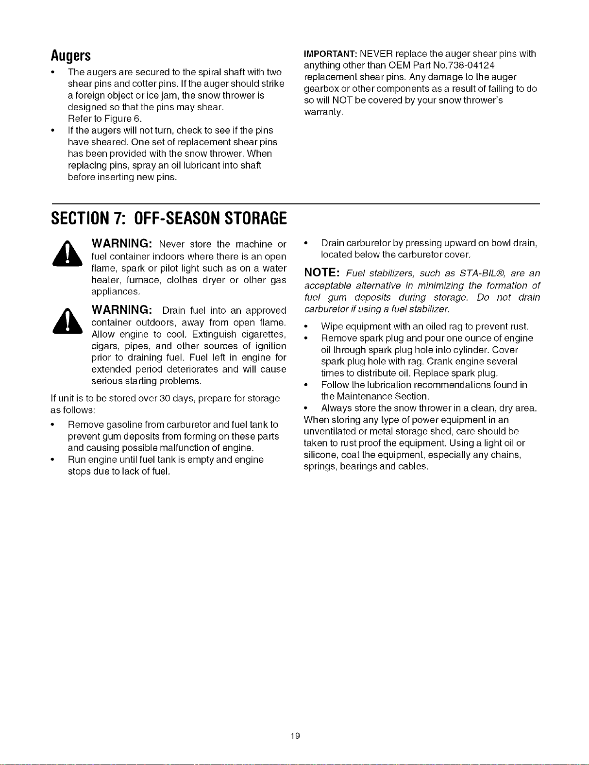
Augers
• The augers are secured to the spiral shaft with two
shear pins and cotter pins. If the auger should strike
a foreign object or ice jam, the snow thrower is
designed so that the pins may shear.
Refer to Figure 6.
• If the augers will not turn, check to see if the pins
have sheared. One set of replacement shear pins
has been provided with the snow thrower. When
replacing pins, spray an oil lubricant into shaft
before inserting new pins.
IMPORTANT:NEVER replace the auger shear pins with
anything other than OEM Part No.738-04124
replacement shear pins. Any damage to the auger
gearbox or other components as a result of failing to do
so will NOT be covered by your snow thrower's
warranty.
SECTION7: OFF-SEASONSTORAGE
WARNING: Never store the machine orfuel container indoors where there is an open
flame, spark or pilot light such as on a water
heater, furnace, clothes dryer or other gas
appliances.
,_ WARNING: Drain fuel into an approved
container outdoors, away from open flame.
Allow engine to cool. Extinguish cigarettes,
cigars, pipes, and other sources of ignition
prior to draining fuel. Fuel left in engine for
extended period deteriorates and will cause
serious starting problems.
If unit is to be stored over 30 days, prepare for storage
as follows:
• Remove gasoline from carburetor and fuel tank to
prevent gum deposits from forming on these parts
and causing possible malfunction of engine.
• Run engine until fuel tank is empty and engine
stops due to lack of fuel.
• Drain carburetor by pressing upward on bowl drain,
located below the carburetor cover.
NOTE: Fuel stabilizers, such as STA-BIL®, are an
acceptable alternative in minimizing the formation of
fuel gum deposits during storage. Do not drain
carburetor if using a fuel stabilizer.
• Wipe equipment with an oiled rag to prevent rust.
• Remove spark plug and pour one ounce of engine
oil through spark plug hole into cylinder. Cover
spark plug hole with rag. Crank engine several
times to distribute oil. Replace spark plug.
• Follow the lubrication recommendations found in
the Maintenance Section.
• Always store the snow thrower in a clean, dry area.
When storing any type of power equipment in an
unventilated or metal storage shed, care should be
taken to rust proof the equipment. Using a light oil or
silicone, coat the equipment, especially any chains,
springs, bearings and cables.
19
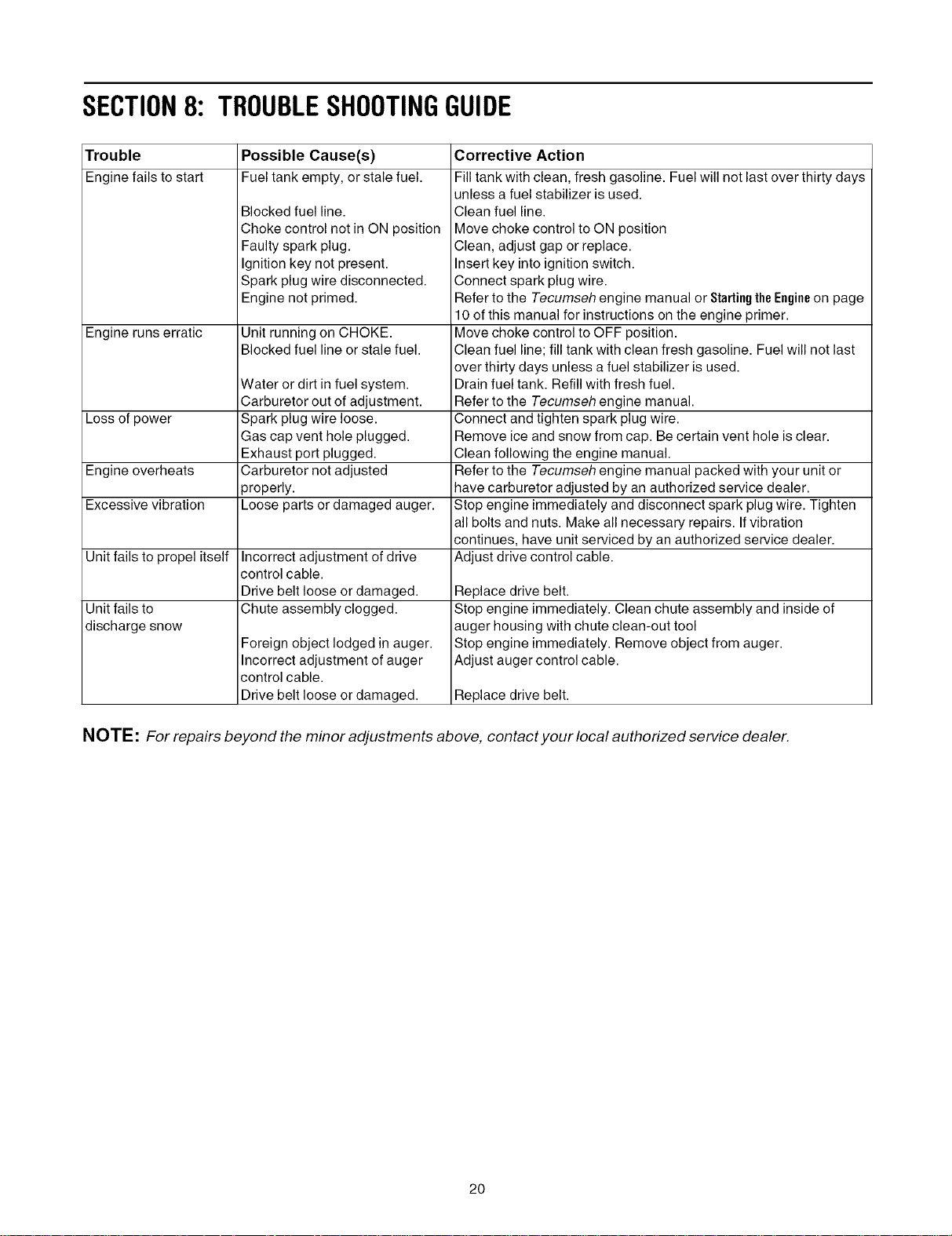
SECTION8: TROUBLESHOOTINGGUIDE
Trouble Possible Cause(s)
Engine fails to start Fuel tank empty, or stale fuel.
Blocked fuel line.
Choke control not in ON position
Faulty spark plug.
Ignition key not present.
Spark plug wire disconnected.
Engine not primed.
Engine runs erratic Unit running on CHOKE.
Blocked fuel line or stale fuel.
Water or dirt in fuel system.
Carburetor out of adjustment.
Loss of power Spark plug wire loose.
Gas cap vent hole plugged.
Exhaust port plugged.
Engine overheats Carburetor not adjusted
properly.
Excessive vibration Loose parts or damaged auger.
Unit fails to propel itself Incorrect adjustment of drive
control cable.
Drive belt loose or damaged.
Unit fails to Chute assembly clogged.
discharge snow Foreign object lodged in auger.
Incorrect adjustment of auger
control cable.
Drive belt loose or damaged.
Corrective Action
Fill tank with clean, fresh gasoline. Fuel will not last over thirty days
unless a fuel stabilizer is used.
Clean fuel line.
Move choke control to ON position
Clean, adjust gap or replace.
Insert key into ignition switch.
Connect spark plug wire.
Refer to the Tecumseh engine manual or StartingtheEngineon page
10 of this manual for instructions on the engine primer.
Move choke control to OFF position.
Clean fuel line; fill tank with clean fresh gasoline. Fuel will not last
over thirty clays unless a fuel stabilizer is used.
Drain fuel tank. Refill with fresh fuel.
Refer to the Tecumseh engine manual.
Connect and tighten spark plug wire.
Remove ice and snow from cap. Be certain vent hole is clear.
Clean following the engine manual.
Refer to the Tecumseh engine manual packed with your unit or
have carburetor adjusted by an authorized service dealer.
Stop engine immediately and disconnect spark plug wire. Tighten
all bolts and nuts. Make all necessary repairs. Ifvibration
continues, have unit serviced by an authorized service dealer.
Adjust drive control cable.
Replace drive belt.
Stop engine immediately. Clean chute assembly and inside of
auger housing with chute clean-out tool
Stop engine immediately. Remove object from auger.
Adjust auger control cable.
Replace drive belt.
NOTE: For repairs beyond the minor adjustments above, contact your local authorized service dealer.
2O

NOTES
21
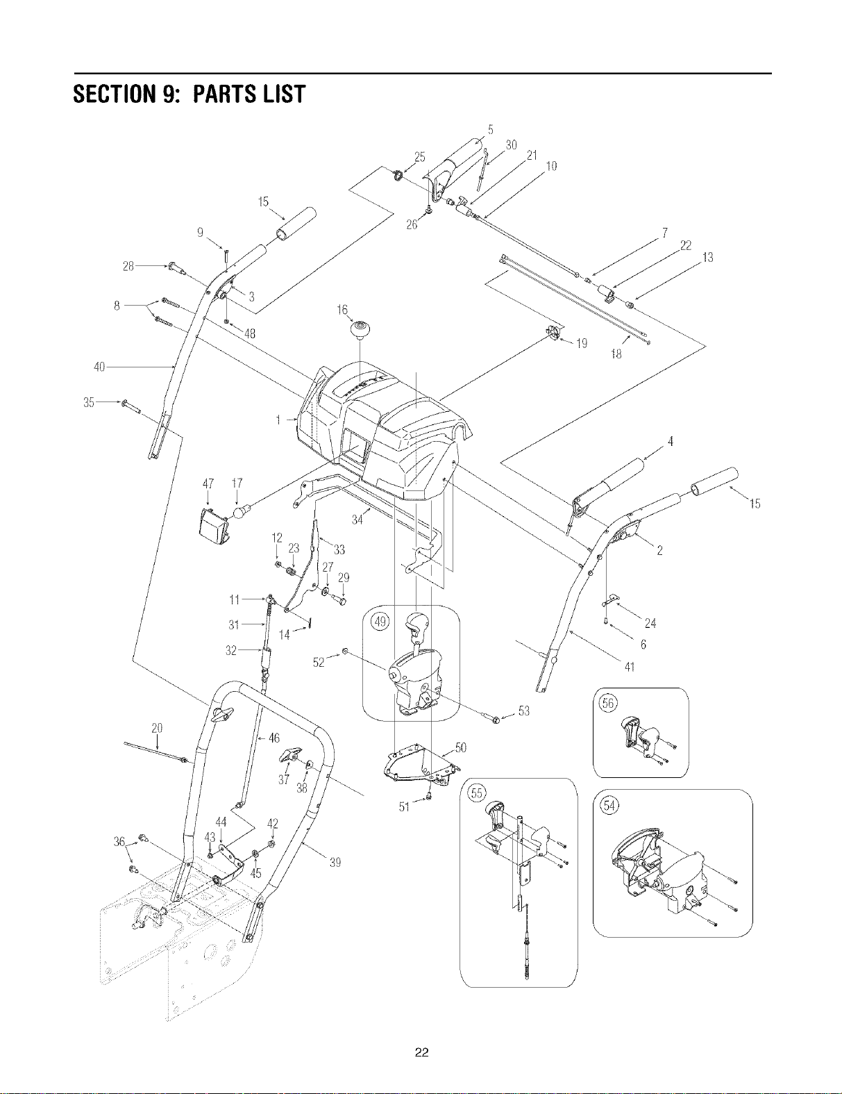
SECTION9: PARTSLIST
9
15
4O
25
530 21 10
18
22 13
2O
47 17
29
39
53
_15
22
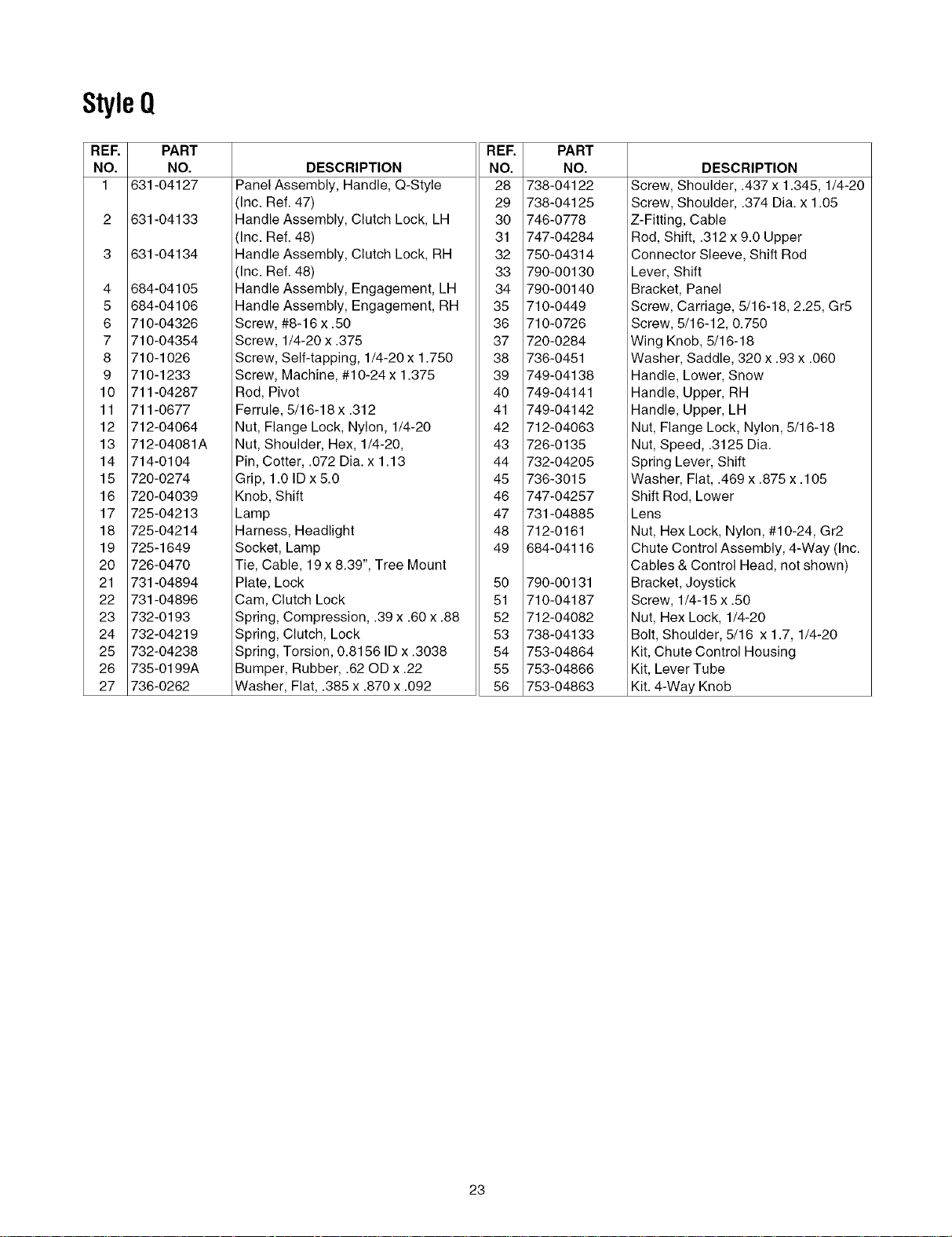
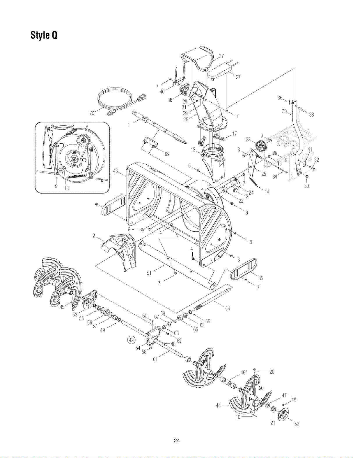
StyleQ
REF. PART
NO. NO.
1 631-04127
2 631-04133
3 631-04134
4 684-04105
5 684-04106
6 710-04326
7 710-04354
8 710-1026
9 710-1233
10 711-04287
11 711-0677
12 712-04064
13 712-04081A
14 714-0104
15 720-0274
16 720-04039
17 725-04213
18 725-04214
19 725-1649
20 726-0470
21 731-04894
22 731-04896
23 732-0193
24 732-04219
25 732-04238
26 735-0199A
27 736-0262
DESCRIPTION
Panel Assembly, Handle, Q-Style
Inc. Ref. 47)
Handle Assembly, Clutch Lock, LH
Inc. Ref. 48)
Handle Assembly, Clutch Lock, RH
Inc. Ref. 48)
Handle Assembly, Engagement, LH
Handle Assembly, Engagement, RH
Screw, #8-16 x .50
Screw, 1/4-20 x .375
Screw, Self-tapping, 1/4-20 x 1.750
Screw, Machine, #10-24 x 1.375
Rod, Pivot
Ferrule, 5/16-18 x .312
Nut, Flange Lock, Nylon, 1/4-20
Nut, Shoulder, Hex, 1/4-20,
Pin, Cotter, .072 Dia. x 1.13
Grip, 1.0 ID x 5.0
Knob, Shift
Lamp
Harness, Headlight
Socket, Lamp
Tie, Cable, 19 x 8.39", Tree Mount
Plate, Lock
Cam, Clutch Lock
Spring, Compression, .39 x .60 x .88
Spring, Clutch, Lock
Spring, Torsion, 0.8156 ID x .3038
Bumper, Rubber, .62 OD x .22
Washer, Fiat, .385 x .870 x .092
REF.
NO.
28
29
30
31
32
33
34
35
36
37
38
39
4O
41
42
43
44
45
46
47
48
49
5O
51
52
53
54
55
56
PART
NO.
738-04122
738-04125
746-0778
747-04284
750-04314
790-00130
790-00140
710-0449
710-0726
720-0284
736-0451
749-04138
749-04141
749-04142
712-04063
726-0135
732-04205
736-3015
747-04257
731-04885
712-0161
684-04116
790-00131
710-04187
712-04082
738-04133
753-04864
753-04866
753-04863
DESCRIPTION
Screw, Shoulder, .437 x 1.345, 1/4-20
Screw, Shoulder, .374 Dia. x 1.05
Z-Fitting, Cable
Rod, Shift, .312 x 9.0 Upper
Connector Sleeve, Shift Rod
Lever, Shift
Bracket, Panel
Screw, Carriage, 5/16-18, 2.25, Gr5
Screw, 5/16-12, 0.750
Wing Knob, 5/16-18
Washer, Saddle, 320 x .93 x .060
Handle, Lower, Snow
Handle, Upper, RH
Handle, Upper, LH
Nut, Flange Lock, Nylon, 5/16-18
Nut, Speed, .3125 Dia.
Spring Lever, Shift
Washer, Flat, .469 x .875 x .105
Shift Rod, Lower
Lens
Nut, Hex Lock, Nylon, #10-24, Gr2
Chute Control Assembly, 4-Way (Inc.
Cables & Control Head, not shown)
Bracket, Joystick
Screw, 1/4-15 x .50
Nut, Hex Lock, 1/4-20
Bolt, Shoulder, 5/16 x 1.7, 1/4-20
Kit, Chute Control Housing
Kit, Lever Tube
Kit. 4-Way Knob
23
StyleQ
9 18
7O
38/31
27
22
34
32
30
56
2
49
51
©54"
68
62
61
4
64
65
e\ 35
7
10 21 52
24
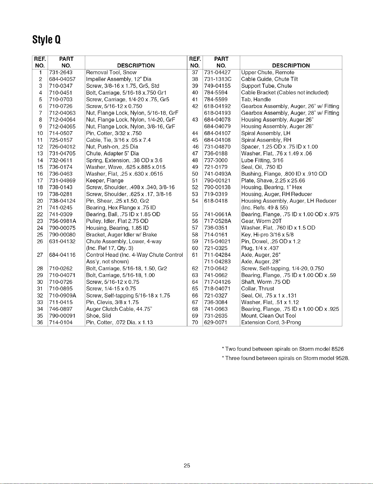
StyleQ
REE PART
NO. NO.
1 731-2643
2 684-04057
3 710-0347
4 710-0451
5 710-0703
6 710-0726
7 712-04063
8 712-04064
9 712-04065
10 714-0507
11 725-0157
12 726-04012
13 731-04705
14 732-0611
15 736-0174
16 736-0463
17 731-04869
18 738-0143
19 738-0281
20 738-04124
21 741-0245
22 741-0309
23 756-0981A
24 790-00075
25 790-00080
26 631-04132
27 684-04116
28 710-0262
29 710-04071
30 710-0726
31 710-0895
32 710-0909A
33 711-0415
34 746-0897
35 790-00091
36 714-0104
REF.
DESCRIPTION NO.
Removal Tool, Snow 37
Impeller Assembly, 12" Dia 38
Screw, 3/8-16 x 1.75, Gr5, Std 39
Bolt, Carriage, 5/16-18 x.750 Grl 40
Screw, Carriage, 1/4-20 x .75, Gr5 41
Screw, 5/16-12 x 0.750 42
Nut, Flange Lock, Nylon, 5/16-18, GrF
Nut, Flange Lock, Nylon, 1/4-20, GrF 43
Nut, Flange Lock, Nylon, 3/8-16, GrF
Pin, Cotter, 3/32 x .750 44
Cable, Tie, 3/16 x .05 x 7.4 45
Nut, Push-on, .25 Dia 46
Chute, Adapter 5" Dia 47
Spring, Extension, .38 OD x 3.6 48
Washer, Wave, .625 x.885 x.015 49
Washer, Flat, .25 x .630 x .0515 50
Keeper, Flange 51
Screw, Shoulder, .498 x .340, 3/8-16 52
Screw, Shoulder, .625 x .17, 3/8-16 53
Pin, Shear, .25 x1.50, Gr2 54
Bearing, Hex Flange x .75 ID
Bearing, Ball, .75 ID x 1.85 OD 55
Pulley, Idler, Flat 2.75 OD 56
Housing, Bearing, 1.85 ID 57
Bracket, Auger Idler w/Brake 58
Chute Assembly, Lower, 4-way 59
(Inc. Ref 17, Qty. 3) 60
Control Head (Inc. 4-Way Chute Control 61
Ass'y, not shown)
Bolt, Carriage, 5/16-18, 1.50, Gr2 62
Bolt, Carriage, 5/16-18, 1.00 63
Screw, 5/16-12 x 0.75 64
Screw, 1/4-15 x 0.75 65
Screw, Self-tapping 5/16-18 x 1.75 66
Pin, Clevis, 3/8 x 1.75 67
Auger Clutch Cable, 44.75" 68
Shoe, Slid 69
Pin, Cotter, .072 Dia. x 1.13 70
PART
NO.
731-04427
731-1313C
749-04155
784-5594
784-5599
618-04192
618-04193
684-04078
684-04079
684-04107
684-04108
731-04870
736-0188
737-3000
721-0179
741-0493A
790-00121
790-00138
719-0319
618-0418
741-0661A
717-0528A
736-0351
714-0161
715-04021
721-0325
711-04284
711-04283
710-0642
741-0662
717-04126
718-04071
721-0327
736-3084
741-0663
731-2635
629-0071
DESCRIPTION
Upper Chute, Remote
Cable Guide, Chute Tilt
Support Tube, Chute
Cable Bracket (Cables not included)
Tab, Handle
Gearbox Assembly, Auger, 26" w/Fitting
Gearbox Assembly, Auger, 28" w/Fitting
Housing Assembly, Auger 26"
Housing Assembly, Auger 28"
Spiral Assembly, LH
Spiral Assembly, RH
Spacer, 1.25 OD x .75 ID x 1.00
Washer, Flat, .76 x 1.49 x .06
Lube Fitting, 3/16
Seal, Oil, .750 ID
Bushing, Flange, .800 ID x .910 OD
Plate, Shave, 2.25 x 25.66
Housing, Bearing, 1" Hex
Housing, Auger, RH Reducer
Housing Assembly, Auger, LH Reducer
(Inc. Refs. 49 & 55)
Bearing, Flange, .75 ID x 1.00 OD x .975
Gear, Worm 20T
Washer, Flat, .760 ID x 1.50D
Key, Hi-pro 3/16 x 5/8
Pin, Dowel, .25 OD x 1.2
Plug, 1/4 x .437
Axle, Auger, 26"
Axle, Auger, 28"
Screw, Self-tapping, 1/4-20, 0.750
Bearing, Flange, .75 ID x 1.00 OD x .59
Shaft, Worm .75 OD
Collar, Thrust
Seal, Oil, .75 x 1 x .131
Washer, Flat, .51 x 1.12
Bearing, Flange, .75 ID x 1.00 OD x .925
Mount, Clean Out Tool
Extension Cord, 3-Prong
*Two found between spirals on Storm model 8526
*Three found between spirals on Storm model 9528.
25
StyleQ
53
57
58 760
50
55
41
52
49
58 62
61
J
33
51 48
56
36 24
3
21
43
14
4
16j
1 12
15 27
14"
26
/34 28
32
38
9
63f67
25
66
26
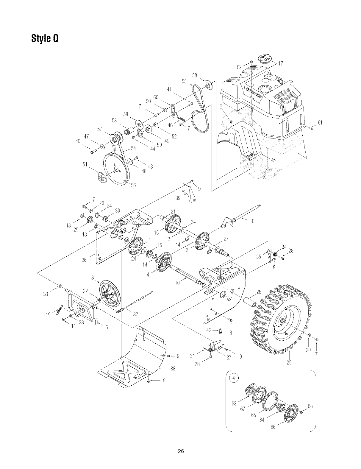
StyleQ
REE PART
NO. NO.
1 617-04026
2 617-04025
3 656-0012A
4 684-04066
5 684-04045
6 684-04139
7 710-0627
8 710-0788
9 710-1652
10 711-04246A
11 712-0711
12 714-0161
13 716-0231
14 716-0136
15 717-04129a
16 717-04137a
17 684-04014A
18 726-0221
19 732-0264
20 736-0242
21 736-04161
22 736-0300
23 736-0105
24 736-0287
25 634-04147
634-04148
26 731-04873
27 738-04095A
28 738-0924
29 741-0563
30 741-0245
31 746-0897
32 746-04086
33 748-0190
34 756-0625
REE
DESCRIPTION NO.
Gear Assembly, 16/44T 35
Gear Assembly, 16/44T 36
Disc Assembly, Friction Wheel, .375 37
Wheel Assembly, Friction, 4.90D 38
Support Bracket Ass'y, Friction Wheel 39
PART
NO.
784-5687A
790-00072
790-00096
790-00054
790-00055
DESCRIPTION
Guide Bracket, Auger Cable
Frame
Guide Bracket, Front, Auger Cable
Cover, Frame
Roller Bracket, Drive Cable
Shift Assembly, Rod 40
Screw, 5/16-24 x .750, Gr5 41
Screw, 1/4-20 x 1.000 42
Screw, 1/4-20 x .625 43
Hex Shaft, Drive, .75 44
Nut, Jam, 3/8-24, Gr2 45
Key, Hi-pro 3/16 x 5/8 46
Ring, E Type, .750 47
Ring, E-Type, .875 48
Pinion, 16T 49
Gear, 44T 50
Shroud Assembly, Troy-Bilt 51
Nut, Speed, .500 52
Extension Spring 53
Washer, Bell, .340 x .872 x .060 54
Washer, Fiat, .75 x 1.00 x .060 55
Washer, Flat, .406 x .875 x .059 56
Washer, Bell, .375 x .870 x .063 57
Washer, Flat, .793 x 1.24 x .060 58
Wheel, Complete, 15 x 5 x 6, LH 59
Wheel, Complete,15 x 5 x 6, RH 60
Spacer, 1.25 OD x .75 ID x 3.00 61
Axle, .75 x 22 62
Screw, 1/4-28 x .375 63
Bearing, Ball, 17 x 40 x 12 64
Bearing, Hex Flange x .75 ID 65
Cable, Auger, 44.75 66
Cable, Drive, 41.75 67
Spacer, .508 ID x .75 OD x .68 68
Roller, Cable
710-0191
710-0597
710-0654A
710-1245B
712-04064
731-04792
732-0710
736-0247
736-0505
741-0919
748-0234
748-04053
750-04230
750-04303
754-04050
754-0456
756-04109
756-04113
756-04114
790-00062
790-00082
710-04082
712-3004A
618-04169
718-04070
735-0243B
790-00010
790-00011
710-0896
Screw, 3/8-24 x 1.25, Gr8
Screw, 1/4-20 x 1.00, Gr5
Screw, Sems, 3/8-16 x 1.00
Screw, 5/16-24 x .875, Gr8
Nut, Flange Lock, Nylon, 1/4-20, GrF
Cover, Belt
Spring, Extension, .38 OD x 2.68
Washer, Flat, .406 x 1.25 x.157
Washer, Flat, .34 x 1.50 x .150
Bearing, Ball, 20 x 47 x 14
Shoulder Spacer
Pulley, Adapter, .75 Dia.
Spacer, .777 OD x .260 ID x.550
Spacer, .875 ID x 1.185 OD
V-Belt, 1/2"
V-Belt, 3/8"
Pulley, Auger, 8.1 x .50
Pulley, Half, 2.600 OD
Pulley, Half, 2.20D
Washer, Bearing, 2.12 OD x .255 ID
Idler, Bracket, Drive
Screw, #10-16 x .75
Nut, Flange Lock, 5/16-18, Gr5
Bearing Assembly, Friction Wheel
Hub, Friction Wheel
Friction Wheel Rubber, 4.875 OD
Plate, Friction, 12 Pt 4.60 Dia
Plate, Friction, Extrs, 12 Pt 4.60 Dia
Screw, Self-tapping, 1/4-14 x 0.625
Wheel Assembly
Complete
634-04147
634-04148
Wheel Size
15x5
15x5
Rim Only
634-04151
634-04151
Tire Only
734-04012
734-04012
Air Valve
734-0255
734-0255
27
MANUFACTURER'S LIMITED WARRANTY FOR:
®
m m
The limited warranty set forth below is given by Troy-Bilt LLC
with respect to new merchandise purchased and used in the
United States and/or its territories and possessions, and by
MTD Products Limited with respect to new merchandise
purchased and used in Canada and/or its territories and
possessions (either entity respectively, "Troy-Bilff).
"Troy-Bilt" warrants this product (excluding its normal wear
parts as described below) against defects in material and
workmanship for a period of two (2) years commencing on the
date of original purchase and will, at its option, repair or
replace, free of charge, any part found to be defective in
materials or workmanship. This limited warranty shall only
apply if this product has been operated and maintained in
accordance with the Operator's Manual furnished with the
product, and has not been subject to misuse, abuse,
commercial use, neglect, accident, improper maintenance,
alteration, vandalism, theft, fire, water, or damage because of
other peril or natural disaster. Damage resulting from the
installation or use of any part, accessory or attachment not
approved by Troy-Bilt for use with the product(s) covered by
this manual will void your warranty as to any resulting
damage.
Normal wear parts are warranted to be free from defects in
material and workmanship for a period of thirty (30) days from
the date of purchase. Normal wear parts include, but are not
limited to items such as: batteries, belts, blades, blade
adapters, grass bags, rider deck wheels, seats, snow thrower
skid shoes, friction wheels, shave plates, auger spiral rubber
and tires.
HOW TO OBTAIN SERVICE: Warranty service is available,
WITH PROOF OF PURCHASE, through your local authorized
service dealer. To locate the dealer in your area:
In the U.S.A.
Check your Yellow Pages, or contact Troy-Bilt LLC at P.O.
Box 361131, Cleveland, Ohio 44136-0019, or call 1-866-840-
6483 or 1-330-558-7220, or log on to our Web site at
www.troybilt.com.
In Canada
Contact MTD Products Limited, Kitchener, ON N2G 4J1, or
call 1-800-668-1238 or log on to our Web site at
www.mtdcanada.com.
This limited warranty does not provide coverage in the
following cases:
a. The engine or component parts thereof. These items
may carry a separate manufacturer's warranty. Refer
to applicable manufacturer's warranty for terms and
conditions.
b. Log splitter pumps, valves, and cylinders have a
separate one- year warranty.
c. Routine maintenance items such as lubricants, filters,
blade sharpening, tune-ups, brake adjustments, clutch
adjustments, deck adjustments, and normal
m_m
deterioration of the exterior finish due to use or
exposure.
d. Service completed by someone other than an
authorized service dealer.
e. Troy-Bilt does not extend any warranty for products
sold or exported outside of the United States and/or
Canada, and their respective possessions and
territories, except those sold through Troy-Bilt's
authorized channels of export distribution.
f. Replacement parts that are not genuine Troy-Bilt parts.
g. Transportation charges and service calls.
h. If Products are used commercially. (Troy-Biltmay
separately offer Limited Commercial Warranties on
certain select products. Ask your dealer or retailer for
details or contact Troy-Bilt Service for more
information.)
No implied warranty, including any implied warranty of
merchantability of fitness for a particular purpose,
applies after the applicable period of express written
warranty above as to the parts as identified. No other
express warranty, whether written or oral, except as
mentioned above, given by any person or entity,
including a dealer or retailer, with respect to any product,
shall bind Troy-Bilt. During the period of the warranty, the
exclusive remedy is repair or replacement of the product
as set forth above.
The provisions as set forth in this warranty provide the
sole and exclusive remedy arising from the sale. Troy-Bilt
shall not be liable for incidental or consequential loss or
damage including, without limitation, expenses incurred
for substitute or replacement lawn care services or for
rental expenses to temporarily replace a warranted
product.
Some jurisdictions do not allow the exclusion or limitation of
incidental or consequential damages, or limitations on how
long an implied warranty lasts, so the above exclusions or
limitations may not apply to you.
In no event shall recovery of any kind be greater than the
amount of the purchase price of the product sold. Alteration
of safety features of the product shall void this warranty.
You assume the risk and liability for loss, damage, or injury to
you and your property and/or to others and their property
arising out of the misuse or inability to use the product.
This limited warranty shall not extend to anyone other than
the original purchaser or to the person for whom it was
purchased as a gift.
HOW LOCAL LAWS RELATE TO THIS WARRANTY: This
limited warranty gives you specific legal rights, and you may
also have other rights that vary in different jurisdictions.
IMPORTANT: Owner must present Original Proof of
Purchase to obtain warranty coverage.
Troy-Bilt LLC, P.O.BOX361131CLEVELAND,OHIO44136-0019; Phone:1-866-840-6483,1-330-558-7220
MTDCanadaLimited- KITCHENER,ONN2G4J1; Phone1-800-668-1238