
6E/ARS
®
MODEL 917.258691 OWNER'SMANUAL
oAssembly
oOperation
oCustomer Responsibilities
oService and Adjustments
oRepair Parts
CAUTION: Read and follow all safety rules and instructions before operating this equipment.
FOR CONSUMER ASSISTANCE HOT LINE, CALL THiS TOLL FREE NUMBER: 1-800-659-5917
v II I'1 _ IIIIII'lr"llll' ' I111Irlllll
SAFETY RULES
_hb Safe Operation Practices for Ride-On Mowers
IMPORTANT: THIS CUTTING MACHINE IS CAPABLE OF AMPUTATING HANDS AND FEET AND THROWING OBJECTS
FAILURE TO OBSERVE THE FOLLOWING SAFETY INSTRUCTIONS COULD RESULT tN SERIOUS INJURY OR DEATH.
I, GENERAL OPERATION
• Read, understand, and follow all instructions in the manual
and on the machine before starting.
• Only allow responsible adults, who are familiar with the
instructions, to operate the machine.
• Clear the area of objects such as rocks, toys, wire, etc,
which could be picked up and thrown by the blade
• Be sure the area is clear of other people before mowing.. Step
machine if anyone enters the area.
• Never carry passengers.
• Do not mow in reverse unless absolutely necessary Always
look down and behind belore and while backing
• Be aware of the mower discharge direction and do not point
it at anyone. Do not operate the mower without either the
entire grass catcher or the guard in place
• Slow down before turning.
• Never leave a running machine unattended. Always turn off
blades, set parking brake, stop engine, and remove keys
before dismounting.
• Turn off blades when not mowing
• Stop engine before removing grass catcher or unclogging
chute
• Mow only in daylight or good adificiai light
• Do not operate the machine while under the influence of
alcohol or drugs
• Watch for traffic when operating near or crossing roadways
• Use extra care when loading or unloading the machine into
a trailer or truck
II. SLOPE OPERATION
Slopes are a major factor related to loss-of-control and
tipover accidents, which can result in severe injury or death.
A{i slopes require extra caution. If you cannot back up the
slope or if you feel uneasy on it, do not mow it.
DO:
,, Mow up and down slopes, not across.
• Remove obstacles such as rocks, tree limbs, etc
• Watch for holes, ruts, or bumps. Uneven terrain could
overturn the machiner Tatl grass can hide obstac/es_
• Use slow speed Choose a low gear so that you witl not have
to slop or shift whi[e on the slope.
• FoLtow the manufacturer's recommendations for wheel
weights or counterweights to improve siabillty
• Use extra care with grass catchers or other attachments..
These can change the stability of the machine.
• Keep ai! movement on the slopes slow and gradual Do not
make sudden changes in speed or direction.
• Avoid starting or stopping on a slope_ It tires lose traction,
disengage the blades and proceed slowly straight down the
sfope.
DO NOT:
• Donotturnonslopesunlessnecessary, andthen,tumslowty
and gradually downhill, if possible.
• Do not mow near drop-offs, ditches, or embankments The
mower could suddenly turn over if a wheel is over the edge
of a clil{ or ditch, or il an edge caves in
• Do not mow on wet grass. Reduced traction coutd cause
sliding
• Do not try to stabilize the machine by putting your foot on the
ground_
• Do not use grass catcher on steep slopes.
2
III. CHILDREN
Tragic accidents can occur if the operator is not alert to the
presence of childreno Children are often attracted to the
machine and the mowing activity Never assume that
children will remain where you last saw them.
° Keep chitdren out of the mowing area and under the watcllIul
care of another responsible adult.
* Be alert and turn machine off if children enter the area
• Before and when backing, look behind and down for small
children
. Never carry children. They may fail off and be serlous[y
injured or interfere with sate machine operation
. Never allow children to operate the machine
• Use extra care when approaching btind corners, shrubs,
trees, or other objects that may obscure vision.
A
H IHHH,,HI,I
lYe SERVICE
• Use extra care in handling gasoline and other fuels They are
flammable and vapors are explosive.
Use only an approved container
Never remove gas cap or add fuel with the engine
lunning. Atlow engine to cool before relueling Do not
smoke
Never refue_ the machine indoors
Never store the machine or fuel container inside where
there is an open flame, such as a water heater.
o Never run a machine inside a closed area
• Keep nuts and bolts, especially blade attachment bolts, tight
and keep equipment in good condition.
• Never tamper with safety devices Check their proper
operation reguJariy.
• Keep machine free of grass, leaves, or other debris build-up.
Clean oil or fuel spillage. Allow machine to cool before
storing
• Stop and inspect the equipment if you strike an object
Repair, if necessary, before restarting
• Never make adjustments or repa[|s with the engine running
• Grass calchercomponents are subject towear, damage, and
deterioration, which could expose moving pads or aliow
objects to be thrown. Frequently check components and
replace with manufacturer's recommended pads, when nec-
essary.
• Mower blades are sharp and can cut W_ap the blade(s) or
wear gloves, and use extra caution when servicing them
° Check brake operalion frequentlyo Adjust and service as
required.
Look for this symbol to point out im-
portant safety precautions. It means
CAUTION!!! BECOME ALERTt!! YOUR
SAFETY IS INVOLVED.
CAUTION: Always disconnect spark plug
wire and place wire where it cannot contact
spark plug in order to prevent accidental
starting when setting up, transporting,
adjusting or making repairs.
WARNING A
The engine exhaust from this product con-
tains chemicals known to the State of Califor-
nia to cause cancer, birth defects, or other
reproductive harm.

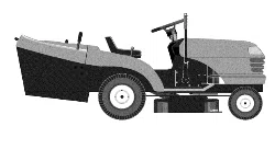
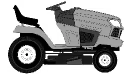
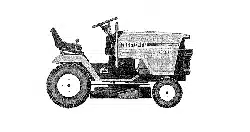
CONGRATULATIONS on your purchase of a Sears
Tractor. It has been designed, engineered and manufac-
tured to give you the best possible dependability and
performance
Should you experience any problem you cannot easily
remedy, please contact your nearest Sears Authorized
Service Center/Department,, We have competent, well-
trained technicians and the proper tools to service or repair
this tractor,
Please read and retain this manual. The instructions wilt
enable you to assemble and maintain your tractor properly°
Always observe the "SAFETY RULES",.
MODEL
NUMBER 917,258691
SERIAL
NUMBER
DATE OF PURCHASE
THE MODELAND SERIAL NUMBERS WILL BE FOUND
ON A PLATE UNDER THE SEAT_
YOU SHOULD RECORD BOTH SERIAL NUMBER AND
DATE OF PURCHASE AND KEEP IN A SAFE PLACE
FOR FUTURE REFERENCE.
MAINTENANCE AGREEMENT
A Sears Maintenance Agreement is available on this prod-
ucL Contact your nearest Sears store for details.
CUSTOMER RESPONSIBlUTIES
• Read and observe the safety rules°
• Folfow a regutar schedule in maintaining, caring for and
using your tractor_
o Follow the instructions under"Customer Responsibili-
ties" and "Storage" sections of this owner's manual.
PRODUCT SPECmFnCATOONS
HORSEPOWER: 18.0
GASOLINE CAPACITY 35 GALLONS
AND TYPE: UNLEADED REGULAR
OIL TYPE (API-SF/SG/SH): SAE 30 (above 32'_F)
SAE 5W-30 (below 32°F)
OIL CAPACITY: W/FILTER: 4.0 PINTS
W/O FILTER: 3.5 PINTS
SPARK PLUG: CHAMPION RV17YC
(GAP: .025")
VALVE CLEARANCE: INTAKE: .003" - 006"
EXHAUST: 013"-.016"
GROUND SPEED (MPH): FORWARD: 5 5
REVERSE: 24
TIRE PRESSURE: FRONT: 14 PSI
REAR: 10 PSI
CHARGING SYSTEM: 15 AMPS @ 3600 RPM
BATTERY: AMP/HR: 30
MIN CCA: 240
CASE SIZE: U1R
BLADE BOLT TORQUE: 30-35 FT. LBS
WARNING: This tractor is equipped with an internal
combustion engine and should not be used on or near any
unimproved forest_covered, brush-covered or grass-cov-
ered land unless the engine's exhaust system is equipped
with a spark arrester meeting applicable local or state laws
(if any). If a spark arrester is used, it should be maintained
in effective working order by the operator.
In the state of California the above is required by law
(Section 4442 of the California Public Resources Code).
Other states may ha_'e similar laws. Federal laws apply on
federal lands. A spark arrester for the muffler is available
through your nearest Sears Authorized Service Center/
Department (See REPAIR PARTS section of this manual),
u iiiiiii, _ ' ,,,............... ,' J,i................... i r,, i , i
LIMITED TWO YEAR WARRANTY ON CRAFTSMAN RIDING EQUIPMENT
For two (2) years from the date of purchase, if this Craftsman Riding Equipment is maintained, lubricated and tuned up according
to the instructions in the owner's manual, Sears will repair or replace, free of charge, any parts found to be defective in material or
workmanship
This Warranty does not cover:
,, Expendable ilems which become worn during normal use, such as blades, spark plugs, air cleaners, belts, etc..
• Tire replacement or repair caused by punctures from outside objects, such as nails, thorns, stumps, or glass.
,, Repairs necessary because of operator abuse, negligence, improper storage or accident or the failure to maintain the
equipment according to the instructions contained in the owner's manual
• Riding equipment used for commercial or rental purposes.
LIMITED 90 DAY WARRANTY ON BATTERY
For ninety (90) days from date of purchase, if any battery included with this riding equipment proves defective in material or
workmanship and our testing determines the battery will not hold a charge, Sears wilt replace the battery at no charge
IN-HOME WARRANTY SERVICE ON YOUR CRAFTSMAN RIDING EQUIPMENT IS AVAILABLE AT NO-CHARGE FOR 30
DAYS FROM THE DATE OF PURCHASE. PLEASE CONTACT YOUR NEAREST SERVICE CENTER. AFTER 30 DAYS FROM
THE DATE OF PURCHASE, WARRANTY SERVICE IS AVAILABLE BY TAKING YOUR CRAFTSMAN RIDING EQUIPMENT TO
YOUR NEAREST SEARS SERVICE CENTER. (IN-HOME WARRANTY SERVICE WILL STILL BE AVAILABLE AFTER 30 DAYS
FROM THE DATE OF PURCHASE BUT A STANDARD TRIP CHARGE WILL APPLY°) THIS WARRANTY APPLIES ONLY
WHILE THIS PRODUCT IS IN THE UNITED STATES°
This Warranty gives you specific legal rights, and you may also have oEher rights which may vary from state to state,.
SEARS, ROEBUCK AND CO.., D/817 WA, HOFFMAN ESTATES, IL 60179
.......... 11,1.... i ..... i,rll..... ,,,,,n .... ,m .............. r
TABLE OF
llil..................................
SAFETY RULES ............................................................ 2
PRODUCT SPECIFICATIONS ...................................... 3
CUSTOMER RESPONSIBILITIES ................ ;....3, 16"19
WARRANTY ........................ ;......................................... 3
TRACTOR ACCESSORIES .......................................... 5
ASSEMBLY ............... :.............................................. 7-10
OPERATION ........................................................... 11-15
CONTENTS
i ii,ilii ,ul, '""" ..... .................. :_
MAINTENANCE SCHEDULE ...................................... 16
SERVICE AND ADJUSTMENTS ............................ 20-25
STORAG E ...................................................................26
TROUBLESHOOTING ............................................ 27-28
REPAIR PARTS - TRACTOR ................................. 30-47
REPAIR PARTS - ENGINE .................................... 48-57
PARTS ORDERING/SERVICE ................ BACK COVER
INDEX
A
Accessories ................................................. 5
Adjustments:
Brake .................................................. 23
Carburetor, ...........................................25
Mowe
Front-To-Back ..............................21
Side-To-Side .............................. 20
Throttle Control Cable ................... 25
Air Filter, Engine .........................................18
Air Screen, Engine .................................19
Assembly .................................................7-I0
B
Battery:
Charging ............................................. 8
Cleaning ........................................... 17
Starting with Weak Battery ........... 24
Storage .................................................26
Terminals ...........................................16
Belt:
Motion Drive
RemovaVReplacement .............23
Mower Belt(s)
RemovaVReplacement ..............22
Blade:
Sharpening ........................................17
Replacement .................................. 17
Brake Adjustment ......................................22
C
Carburetor Adjustment .............................25
Controls, Tractor .......................................11
Customer Responsibilities .............. 16-19
Engine:
Air Filter......................................... 18
Air Screen ............................... 18
Cooling Fins ..................................18
Engine Oil ............................... 14,18
Fuel Filter .................................... 19
Spark Plug(s) .............................. 19
Tractor:
Battery ........................................... 17
Blade ............................................. I7
Lubrication Chart ....................... 16
Maintenance Schedule ............. 16
Tire Care ............................8,17,23
Transaxle .......................................18
Cutting Height, Mower ............................13
E
Electrical:
Interlocks and Relays ................... 24
Schematic ............................................29
Wiring Diagram ............................... 30
Engine:
Air Filter ...............................................18
Air Screen ............................................19
Cooling Fins ........................................ 18
Oil Change ..........................................18
OilLevel...............................................14
Oil Type ................................... 14,18
Preparation ..........................................14
Repair Parts ............................... 48-57
Starting .............................................15
Storage ............................................26
F
Filter:
Air Fitter ................................................18
Fuel .....................................................19
Fuel:
Type ...................................................14
Storage ............................................ 26
Fuse ...................................................... 24
H
Hood Removal/Installation .....................24
L
Leveling Mower Deck ..............................20
Lubrication:
Chart ...............................................16
Engine ............................................18
M
Maintenance Schedule .......................16
Mower:
Adjustment, Front-to-Back ............ 21
Adjustment, Side-to*Side .............. 20
Blade Replacement ..................... 17
Blade Sharpening .......................... 17
Cutting Height ................................... 13
Installation ...................................... 20
Operation........................................14
Removal ..................................................20
Mowing Tips ..............................................15
Muffler ..................................................... 19
Spark Arrester .............................. 3,38
O
Oil:
Cold Weather Conditions ........ 14,18
Engine ............................................... 18
Storage ............................................ 26
Operation ......................................... 11-15
4
Operating Mower ........................ 14
Options:
Accessories .................................... 5
Spark Attester ..................................3,38
P
Parking Brake .................................. 12-13
Parts Bag ............................................. 6
Parts, Replacement/Repair ............. 30-47
Product Specifications ............................ 3
R
Repair Parts ...................................... 30-47
S
Safety Rules ............................................ 2
Seat ............................................................ 8
Service and Adjustments ....................20-25
Carburetor ..................................... 25
Fuse ................................................... 24
Hood Removaltlnstallation .... 24
Motion Drive Belt
RemovallReplacement ....... 23
Mower Belt(s)
RemovallReplacement .......... 22
Mower Adjustment
Front*to-Back ........................... 21
Side-to-Side ....................................20
Mower Removal/Installation ........ 20
Tire Care ......................................8,17,23
Slope Guide Sheet .................................. 59
Spark Plug(s) ............................................19
Specifications ...............................................3
Starting the Engine ........................ 14-15
Steering Wheel ................................... ..... 7,23
8topping the Tractor .............................. 13
Storage ...........................................................26
T
Throttle Control CaMe Adjustment . 25
Tires.................................................. 8,17,23
Troubleshooting Chart ........................27-28
Transaxle ............................................... 18
W
Warranty ............................................................3
Wiring Diagram ...........................................30
Wiring Schematic ...........................................29
ACCESSORIES AND ATTACHMENTS
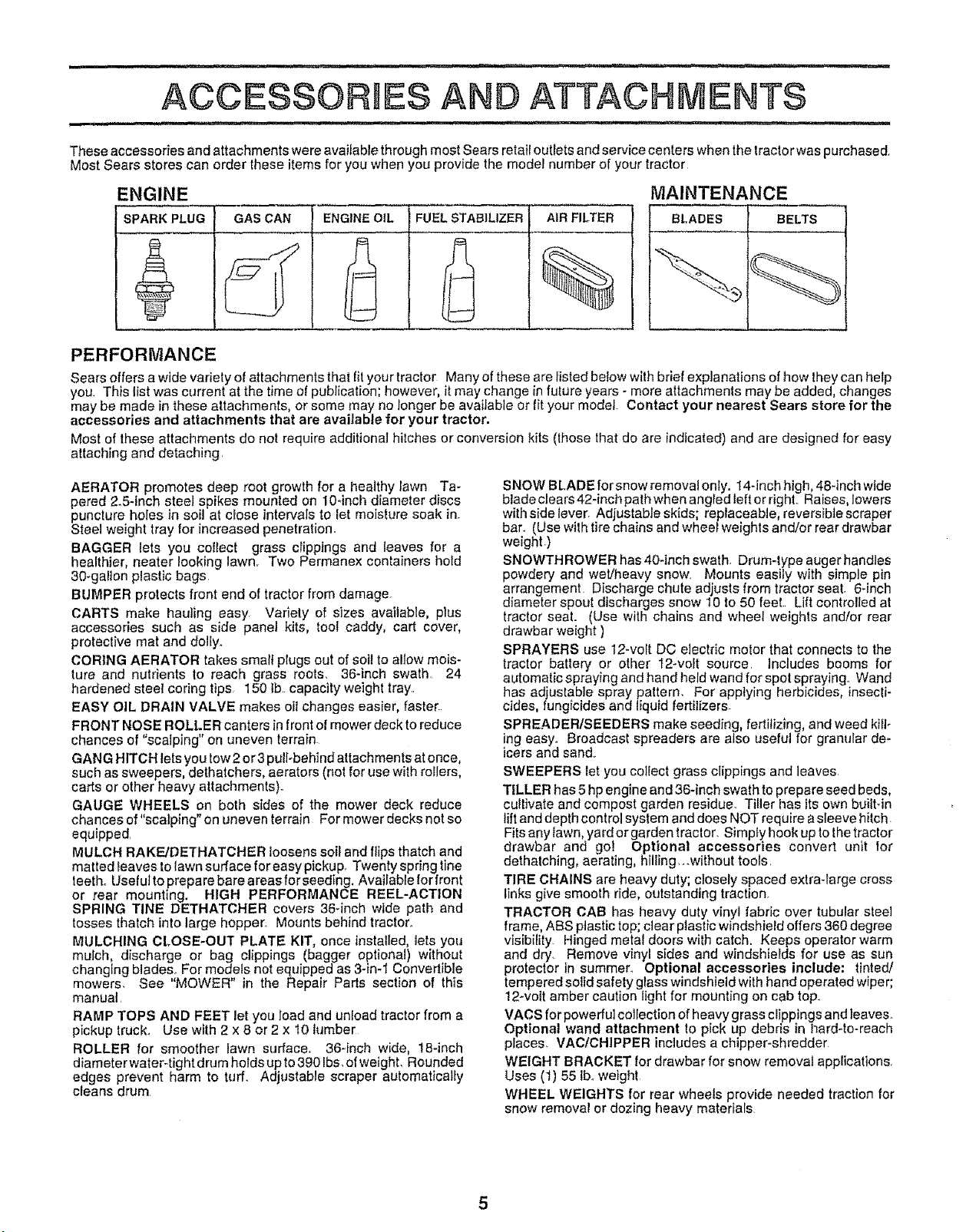
These accessories and attachments were available through most Sears reta!i outlets and service centers when the tractor was purchased,
Most Sears stores can order these items for you when you provide the mode! number of your tractor
MAINTENANCE
[ BLADES 1 BELTS
ENGINE
SPARK PLUG GAS CAN
FUEL STABILIZER AIR FILTER
%
PERFORMANCE
Sears offers a wide variety of attachments that fityour tractor Many of these are Iisted below wlth brief explanations of how they can help
you, This list was current at the time ol publication; however, itmay change infuture years - more attachments may be added, changes
may be made in these attachments, or some may no Ionger be available or fit your model Contact your nearest Sears store for the
accessories and attachments that are available for your tractor.
Most of these attachments do not require additional hitches or conversion kits (lhose that do are indicated) and are designed for easy
attaching and detaching
AERATOR promotes deep root growth for a healthy lawn Ta-
pered 2.5-inch steel spikes mounted on 104nch diameter discs
puncture holes in soil at close intervals to let moisture soak in.
Steel weight tray for increased penetration
BAGGER lets you coIIect grass clippings and leaves for a
healthier, neater looking lawnr Two Permanex containers hold
30-gallon plastic bags
BUMPER protects front end of tractor from damage.
CARTS make hauling easy Variety of sizes available, plus
accessories such as side panel kits, tool caddy, cart cover,
protective mat and doily.
CORING AERATOR takes small plugs out of soi! to allow mois-
ture and nutrients to reach grass roots. 36-inch swath 24
hardened steel coring tips 150 Ib capacity weight tray,.
EASY OIL DRAIN VALVE makes oil changes easier, faster
FRONT NOSE ROLLER canters in front of mower deck to reduce
chances of "scalping" on uneven terra!n
GANG HITCH lets you tow2 or3 pulFbehlnd attachments at once,
such as sweepers, dethatchers, aerators (not for use with rollers,
carts or other heavy attachments)°
GAUGE WHEELS on both s!des of the mower deck reduce
chances of "scalping" on uneven terrain For mower decks not so
equipped.
MULCH RAKE/DETHATCHER loosens suit and flips thatch and
matted _eaves tolawn surface for easy pickup. Twenty spring tine
teeth. Usefut to prepare bare areas for seeding. Available for front
or rear mounting. HIGH PERFORMANCE REEL-ACTION
SPRING TINE DETHATCHER covers 36qnch wide path and
tosses thatch into large hopper, Mounts behind tractor,,
MULCHING CLOSE-OUT PLATE KIT, once installed, lets you
mulch, discharge or bag clippings (bagger optional) without
changing blades, For models not equipped as 34n-1 Convertible
mowers. See "MOWER" in the Repair Parts section of this
manual
RAMP TOPS AND FEET let you load and unload tractor from a
pickup truck., Use with 2 x 8 or 2 x 10 hJmber
ROLLER for smoother lawn surface, 36-inch wide, 18-inch
diameter water4ight drum holds up to390 Ibs.ofwe!ght Rounded
edges prevent harm to turf. Adjustable scraper automatically
cleans drum
SNOW BLADE forsnow removal only. 14-inch high, 48-inch wide
blade clears 42-inch path when angled left or right, Raises, lowers
with side lever Adjustable skids; replaceable, reversible scraper
bar. (Use with tire chains and wheel weights and/or rear drawbar
weight _)
SNOWTH ROWER has 40-inch swath. Drum-type auger handles
powdery and wet/heavy snow, Mounts easily with simple pin
arrangement Discharge chute adjusts from tractor seat, 6-inch
diameter spout discharges snow 10 to 50 feel Lift controlled at
tractor seat. (Use with chains and wheel weights and/or rear
drawbar weight )
SPRAYERS use 12-volt DC electric motor that connects to the
tractor battery or other 12-volt source, includes booms for
automatic spraying and hand held wand for spot spraying. Wand
has adjustable spray pattern. For applying herbicides, insecti-
cides, fungicides and liquid fertilizers_
SPREADER/SEEDERS make seeding, fertilizing, and weed kiN.
ing easy° Broadcast spreaders are also useful for granular de-
icers and sand.,
SWEEPERS let you collect grass clippings and leaves
TILLER has 5 hp engine and 36-inch swath to prepare seed beds,
cultivate and compost garden residue Tiller has its own builtqn
lift and depth control system and does NOT require asleeve hitch.
Fits any lawn, yard or garden tractor, Simply hook up tothe tractor
drawbar and got Optional accessories convert unit for
dethatching, aerating, hilling _.without tools,
TIRE CHAINS are heavy duty; closely spaced extra-large cross
links give smooth ride, outstanding traction.
TRACTOR CAB has heavy duty vinyl fabric over tubular steel
frame, ABS plastic top; clear plastic windshield offers 360 degree
visibility Hinged metal doors with catch. Keeps operator warm
and dry, Remove vinyl sides and windshierds for use as sun
protector in summer.. Optional accessories include: tinted/
tempered solid safety glass windshield with hand operated wiper;
12-volt amber caution light for mounting on cab top.
VACS for powerful collection of heavy grass clippings and leaves
Optional wand attachment to pick up debris in l_ardqo-reach
places. VAC/CHIPPER includes a chipper-shredder
WEIGHT BRACKET for drawbar for snow removal appflcations,
Uses (t) 55 tb. weight
WHEEL WEIGHTS for rear wheels provide needed traction for
snow removal or dozing heavy materials
CONTENTS OF HARDWARE PACK
........... t Ir .................. iiiiir,nfflIW, ii ,,.1, ,
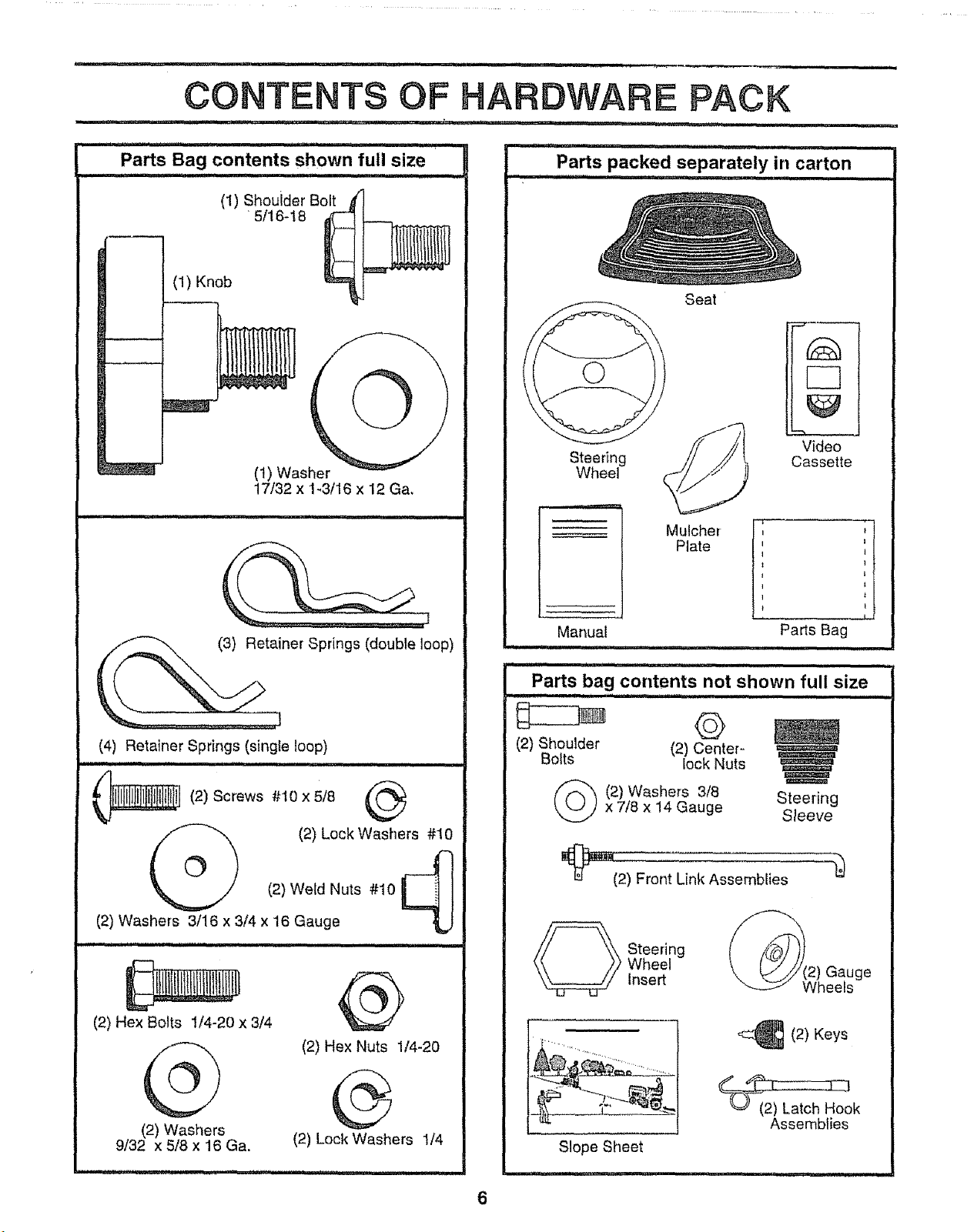
Parts Bag contents shown full size
(1) Shouider Bolt
' 5/16-18
(!) Knob
(1) Washer
17/32 x 1-3/16 x 12 Ga,
ner Springs (double loop)
(4) Retainer Springs (single loop)
,I,HI i i,iii ,, ,,,,,,',,,,,,, i i
_ (2) Screws #10 x 5/8
(2) Lock Washers #10
(2) Weld Nuts #10
(2) Washers 3/16 x 3/4 x 16 Gauge
(2) Hex Bolts 1/4-20 x 3/4
(2) Washers
9/32 x 5/8 x 16 Ga.
@
(2) Hex Nuts 1/4-20
®
(2) Lock Washers !/4
iii i ................... ...................r =
Parts packed separately in carton
................... i iii1,
©
Steering
Wheel
Seat
Mulcher
Plate
Video
Cassette
I ,t
Parts Bag
ii, ,,,,
Manual
,i i
i , H ,ll!ll ,HII, ii1,,,i ,,,H
Parts bag contents not shown full size
i H, i , i ................... i HHI, I
©
(2) Shoulder (2) Center-
Bolts lock Nuts
(_(2) Washers 3/8 Steering
x 7/8 x 14 Gauge Sleeve
_nt Link Assemblies
_ teering
Wheel
Insert
Slope Sheet
,i..............................
_(2) Keys
Assemblies
6

ASSEMBLY
Your new tractor has been assembled at the factory with exception ofthose parts left unassembled for shipping purposes.
To ensure safe and proper operation of yourtractor all parts and hardware you assemble must be tightened securely,. Use
the correct tools as necessary to insure proper tightness,
TOOLS REQUIRED FOR ASSEMBLY
A socket wrench set will make assembly easier_ Standard
wrench sizes are listed,
(2) 7/16" wrenches Pliers
(1) 9/16" wrench Tire pressure gauge
(1) 3/4" Socket w/drive ratchet Phillips Screwdriver
Utility knife
When right or left hand is mentioned in this manual, it
means when you are in the operating position (seated
beh{nd the steering wheel),
TO REMOVE TRACTOR FROM CARTON
UNPACK CARTON
• Remove all accessible loose parts and parts cartons
from carton (See page 6).
o Cut, from top to bottom, along lines on al! four corners
of carton, and fay panels flat.
. Remove mower and packing materials.
= Check for any additional loose parts or cartons and
remove.
STEERING__
_ TEERING WHEEL
INSERT
.- HEX LOCKNUT
FLAT WASHER
STEERING
WHEE I"
I I / / /
/ t 1/ /
_'_._ zI
FIG, 1
BEFORE ROLLING TRACTOR OFF SKiD
ATTACH STEERING WHEEL (See Fig. 1)
o Remove locknut and large flat washer from steering
shaft.
• Position front wheels of the tractor so they are pointing
straight forward.
• Slide the steering sleeve over the steering shaft,
. Position steering wheel so cross bars are horizontal
(left to right) and slide onto adapter.
• Secure steering wheel to steering shaft with iocknut
and large flat washer previously removed° Tighten
securely.
,, Snap steering wheel insert into center of steering
wheel,
• Remove protective materials from tractor hood and
gdll,
IMPORTANT: CHECK FOR AND REMOVE ANY STAPLES
IN SKID THAT MAY PUNCTURE TIRES WHERE TRACTOR
IS TO ROLL OFF SKID,
TO ROLL TRACTOR OFF SKID (See Operation
section for location and function of controls)
• Press lift lever plunger and raise attachment lift lever to
its highest position_
o Release parking brake by depressing clutch/brake
pedal°
= Place freewheel control in freewheeling position to
disengage transmission (See "TO TRANSPORT" in
the Operation section of this manual).
• Roll tractor backwards off skid.
7
............. i .......... iii
LY
ill i i iUl .... i ....
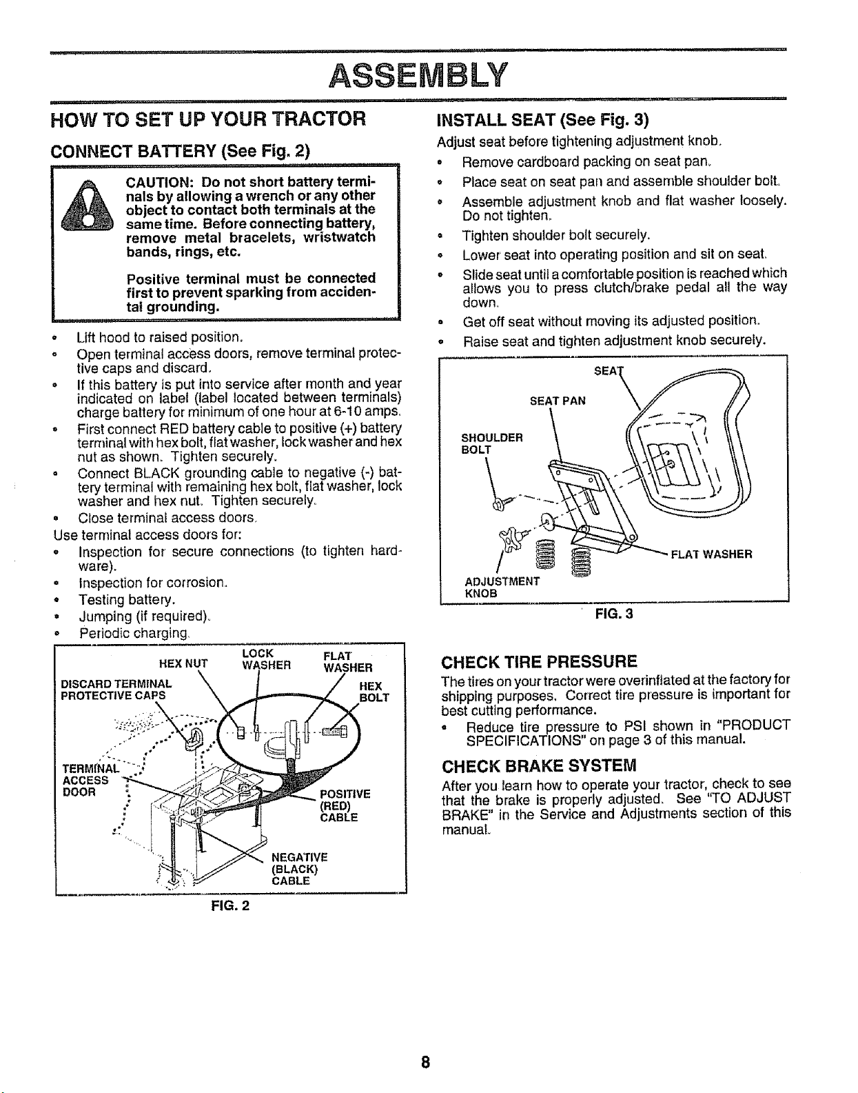
HOW TO SET UP YOUR TRACTOR INSTALLSEAT(See Fig. 3)
CONNECT BATTERY (See Fig. 2) Adjust seat before tightening adjustment knob,
........_ ii ilU ........ i.i ii iliiiilillilii I
CAUTION: Do not short battery termi- •
nals by allowing a wrench or any other
object to contact both terminals at the °
same time. Before connecting battery,
remove metal bracelets, wristwatch
bands, rings, etc.
Positive terminal must be connected
first to prevent spartdng from acciden-
tal grounding.
...................... ii iliii I I
° Lift hood to raised position.
° Open terminal access doors, remove terminal protec-
tive caps and discard.
• If this battery is put into service after month and year
indicated on label (label located between terminals)
charge battery for minimum of one hour at 6-10 amps,
° First connect RED battery cable to positive (+) battery
terminal with hex bolt, fiat washer, lock washer and hex
nut as shown. Tighten securely.
= Connect BLACK grounding cable to negative (-) bat-
tery terminal with remaining hex belt, flat washer, lock
washer and hex nut. Tighten securely°
= Ctose terminal access doors.
Use terminal access doors for:
= Inspection for secure connections (to tighten hard-
ware).
• inspection for co[rosion°
• Testing battery.
• Jumping (if required)°
Periodic charging,
LOCK FLAT
HEX NUT WASHER WASHER
D,SCARD TERM,NAL _ I / HEoXLT
PROTECTIVE CAPS i._._B
ACCESS
DOOR "_/1_ _ POSITIVE
__ - - (RED)
Remove cardboard packing on seat pan.
Place seat on seat pan and assemble shoulder bolto
Assemble adjustment knob and flat washer loosety.
Do not tighten°
. Tighten shoulder bolt securely.
° Lower seat into operating position and sit on seat,
° Slide seat until acomfortable position isreached which
allows you to press clutch/brake pedal all the way
down.
. Get off seat without moving its adjusted position.
o Raise seat and tighten adjustment knob securely.
SEAT PAN
SHOULDER
BOLT
ADJUSTMENT
KNOB
FIG. 3
"FLAT WASHER
CHECK TIRE PRESSURE
The tires onyourtractor'were overinflated at the factory for
shipping purposes, Correct tire pressure is important fer
best cutting performance.
= Reduce tire pressure to PSI shown in "PRODUCT
SPECIFICATIONS" on page 3 of this manual.
CHECK BRAKE SYSTEM
After you learn how to operate your tractor, check to see
that the brake is properly adjusted, See 'q'O ADJUST
BRAKE" in the Service and Adjustments section of this
manual
FIG. 2
8
= r= H =, == = HHHHH = rrH'IHH= ' ='=" "H'"'=H" = H,IHI,
ASSEMBLY
,,,H,,,,,=,,, = i ' ,,=,H,,=...... , .................
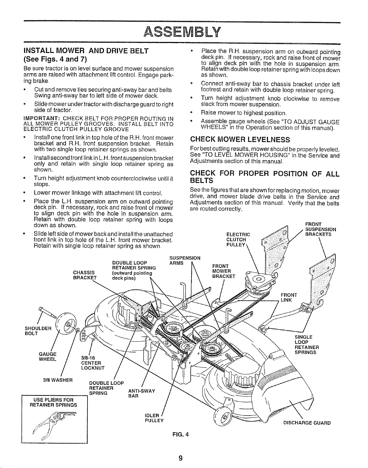
INSTALL MOWER AND DRIVE BELT • Place the R.Ho suspension arm on outward pointing
(See Figs. 4 and 7) deck pin. If necessary, rock and raise front of mower
to align deck pin with the hole in suspension arm
Be sure tractor is on levei surface and mower suspension Retain with double loop retainer spring with loops down
arms are raised with attachment lift control Engage park- as shown.
ing brake o Connect anti-sway bar to chassis bracket under left
• Cut and remove ties securing anti-sway bar and belts footrest and retain with double loop retainer spring.,
Swing anti-sway bar to left side of mower deck,, • Turn height adjustment knob clockwise to remove
° Slide mower under tractor with discharge guard to right slack from mower suspension_
side of tractor, o Raise mower to highest position,
o Assemble gauge wheels (See "TO ADJUST GAUGE
WHEELS" in the Operation section of this manual)°
IMPORTANT: CHECK BELT FOR PROPER ROUTING IN
ALL MOWER PULLEY GROOVES. INSTALL BELT_NTO
ELECTRIC CLUTCH PULLEY GROOVE,
o Install one front link in top hole of the R Hofront mower
bracket and R H. front suspension bracket. Retain
with two single loop retainer springs as shown.
o Install second front link in L,H. front suspension bracket
only and retain with single loop retainer spring as
shown,
- Turn height adjustment knob counterclockwise until it
stops.
o Lower mower linkage with attachment lift control.
• Place the Loll suspension arm on outward pointing
deck pin, If necessary, rock and raise front of mower
to align deck pin with the hofe in suspension arm.
Retain with double loop retainer spring with loops
down as shown,,
o SIide left side of mower back and install the unattached
front link in top hole of the Loll. front mower bracket.
Retain with single loop retainer spring as shown,
CHECK MOWER LEVELNESS
For best cutting results, mower should be properly leveled,
See "TO LEVEL MOWER HOUSING" in the Service and
Adjustments section of this manual
CHECK FOR PROPER POSITION OF ALL
BELTS
See the figures that are shown for replacing motion, mower
drive, and mower blade drive belts in the Service and
Adjustments section of this manual Verify that the belts
are routed correctly,,
ELECTRIC
CLUTCH
PULLEY
FRONT
SUSPENSION
BRACKETS
DOUBLE LOOP
RETAINER SPRING
CHASSIS (outward pointing
BRACKET deck pins)
SUSPENSION
ARMS
FRONT
MOWER
BRACKET
FRONT
LINK
SHOULDER
BOLT
GAUGE
WHEEL
3/B WASHER
USEPLIERSFOR
RETAINER SPRINGS
318-16
CENTER
LOCKNUT
DOUBLE LOOP
RETAINER
SPRING
ANTI-SWAY
BAR
IDLER
PULLEY
FIG. 4
SINGLE
LOOP
RETAINER
SPRINGS
DISCHARGE GUARD

, =H'H I N IHHN='
'== HHHH
INSTALL MULCHER PLATE (See Figs. 5 and 6)
• Install two latch hooks to mulcher plate using screw,
washer, lock washer', and weld nut as shown°
NOTE: Pre-assemble we!d nut to latch hook by inserting
weld nut from the top with hook pointing down.
ii
II
O
I
O
Tighten hardware securely.
Raise and hold deflector shield in upright position.
Place front of mulcher ptate over front of mower deck
opening and slide into place, as shownl
Hook front latch into hole on front of mower deck°
Hook rear latch into hole on back of mower deck.
,,, 11,,,==,H=
CAUTION: Do not remove discharge
guard from mower. Raise and hold
guard when attaching mulcher plate
and allow it to rest on plate while in
operation.
DEFLECTOR
SHIELD
LATCH
HOOKS
FIG. 6
TO CONVERT TO BAGGING OR
DISCHARGING
Simply remove mulchet plate and store in a safe place.
Your mower is now ready for discharging or installation of
optional grass catcher accessory.
NOTE: tt is not necessary to change btades, The mulcher
blades are designed for discharging and bagging also.
WELD NUT
FROM TilE TOP
HOOK POINTS
DOWN
LOCK
WASHER
WELD.
NUT _ SCREW
LATCH
HOOK
WASHER
MULCHER
PLATE
LOCK
WASHER
FIG. 5
WELD
NUT
1"CHECKLIST
BEFORE YOU OPERATE AND ENJOY YOUR NEW
TRACTOR, WE WISH TO ASSURE THAT YOU RECEIVE
THE BEST PERFORMANCE AND SATISFACTION FROM
THIS QUALITY PRODUCT
PLEASE REVIEW THE FOLLOWING CHECKLIST:
#" All assembly instructions have been completed
I No remaining loose parts in carton°
,/" Battery is properly prepared and charged (Minimum
1 hour at 6 amps)o
,/ Seat is adjusted comfortably and tightened securely.
,,/ AUtires are properly inflated. (For shipping purposes,
the tires were overinflated at the factory).
,l Be sure mower deck is properly leveled side-to-side/
front=to-rear for best cutting results. (Tires must be
propedy inflated for leveling).
€" Check mower and drive belts. Be sure they are routed
properly around pulleys and inside all belt keepers
v' Check wiring, See that all connections are still secure
and wires are properly damped.
i Before driving tractor, be sure freewheel control is in
drive position+
WHILELEARNING HOWTO USE YOUR TRACTOR, PAY
EXTRA ATTENTION TO THE FOLLOWING IMPORTANT
ITEMS.:
,,/ Engine oil is at proper level.
v' Fuel tank is filled with fresh, clean, regular unleaded
gasoline,
t Become familiar with all controls - their location and
function. Operate them before you start the engine.
,/ Be sure brake system is in safe operating condition.
•/ It isimportant to purge the transmission before operat-
ingyour tractor for the first time. Follow proper starting
and transmission purging instructions (See "TO START
ENGINE" and "PURGE TRANSMISSION" in the Op-
eration section of this manuaf)_
10
, i uulu,, i u,u u,ul,
OPERATION
UUl,U,U,,UUM,U,,,,,U,UUI,,,,, I ' II ,I,,I
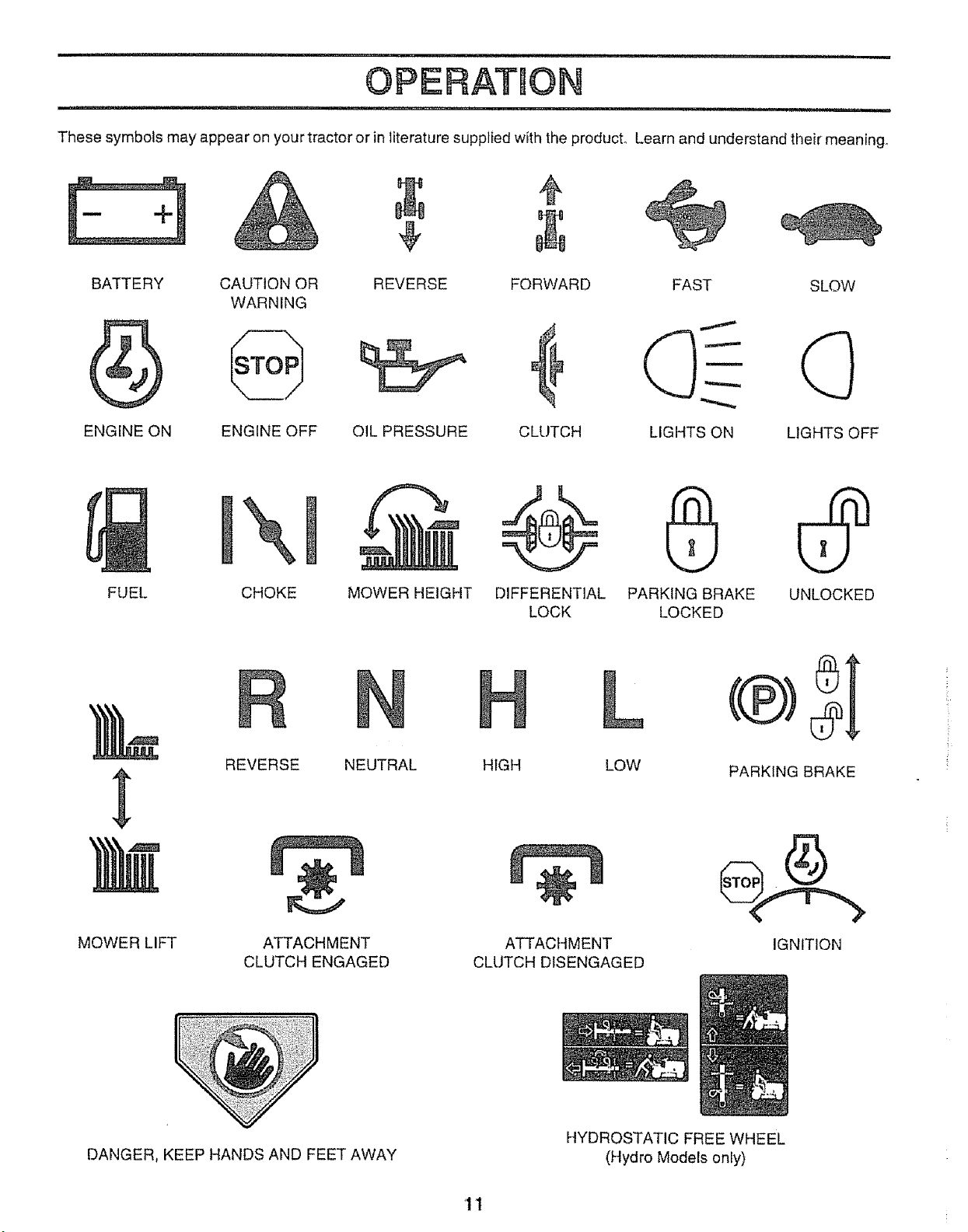
These symbols may appear on your tractor or in literature supplied with the product° Learn and understand their meaning°
BATTERY CAUTION OR REVERSE FORWARD FAST SLOW
WARNING
ENGINE ON ENGINE OFF OIL PRESSURE CLLITCH LIGHTS ON LIGHTS OFF
FUEL
\
CHOKE
MOWER HEIGHT DIFFERENTIAL PARKING BRAKE UNLOCKED
LOCK LOCKED
MOWER LIFT
REVERSE NEUTRAL
ATTACHMENT
CLUTCH ENGAGED
L
HIGH LOW
÷
ATTACHMENT
CLUTCH DISENGAGED
PARKING BRAKE
IGNITION
DANGER, KEEP HANDS AND FEET AWAY
HYDROSTATIC FREE WHEEL
(Hydro Models only)
'11
i HH=H!==!'
OPERATmO
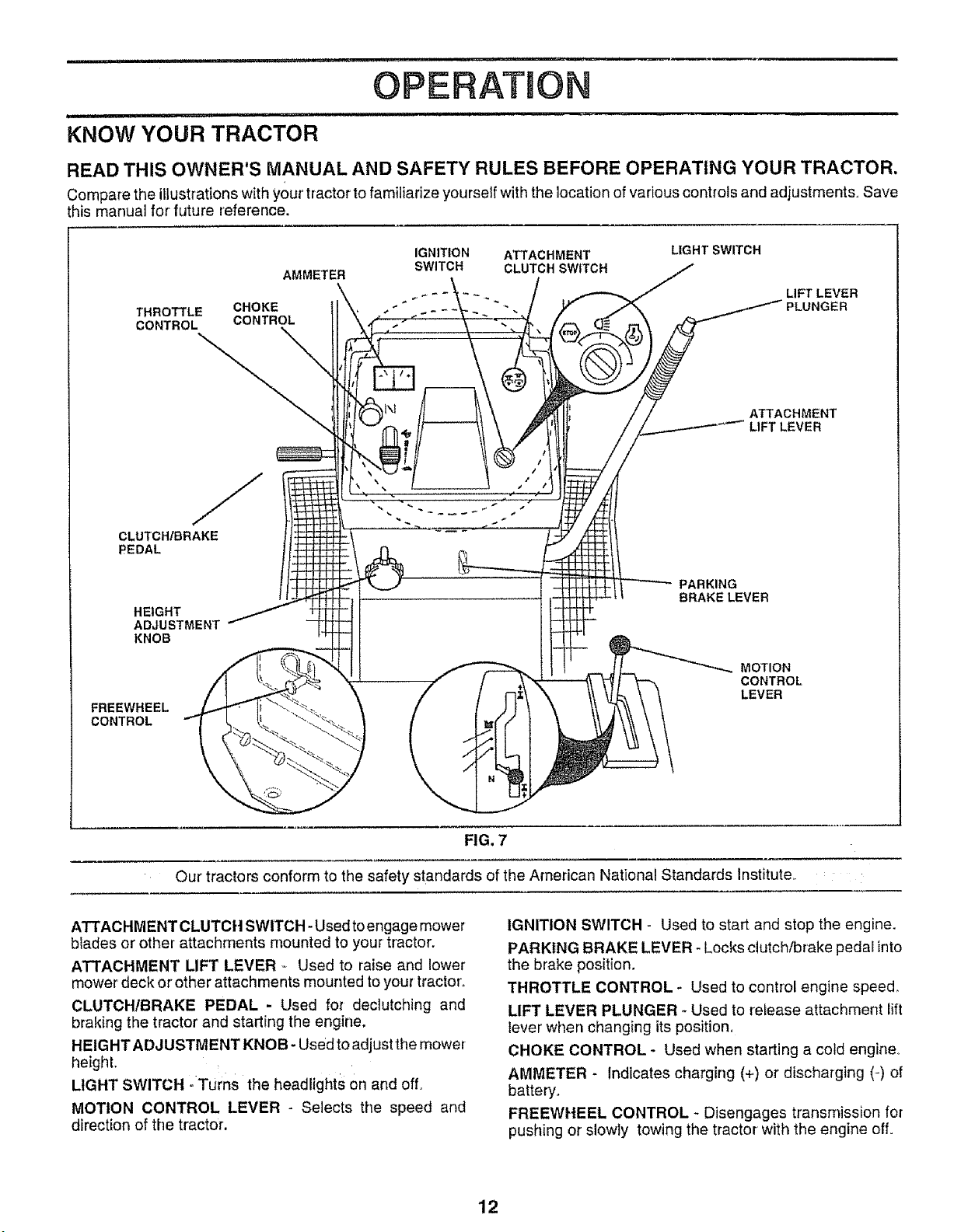
KNOW YOUR TRACTOR
READ THIS OWNER'S MANUAL AND SAFETY RULES BEFORE OPERATING YOUR TRACTOR.
Compare the illustrations with your'tractor to familiarize yourself with the location of various controls and adjustments, Save
this manual for future reference.
AMMETER
THROTTLE CHOKE
CONTROL CONTROL
CLUTCH/BRAKE
PEDAL
HEIGHT
ADJUSTMENT
KNOB
FREEWHEEL
CONTROL
IGNITION ATTACHMENT LIGHT SWITCH
SWITCH CLUTCH SWITCH
PARKING
BRAKE LEVER
ATTACHMENT
LIFT LEVER
MOTION
CONTROL
LEVER
FIG. 7
Our tractors conform to the safety standards of the American National Standards lnstitute_
ATTACHMENT CLUTCH SWITCH- Used toengage mower
blades or other attachments mounted to your tractor.
ATTACHMENT LIFT LEVER _ Used to raise and lower
mower' deck or other attachments mounted toyour tractor',,
CLUTCH/BRAKE PEDAL - Used for declutching and
braking the tractor and starting the engine,
HEIGHT ADJUSTMENT KNOB - Used to adjust the mower
height.
LIGHT SWITCH oTurns the headlights on and off,
MOTION CONTROL LEVER - Selects the speed and
direction of the tractor.
IGNITION SWITCH - Used to start and stop the engine.
PARKING BRAKE LEVER - Locks clutch/brake pedal into
the brake position,
THROTTLE CONTROL _ Used to control engine speed
LIFT LEVER PLUNGER - Used to release attachment lift
lever when changing its position,
CHOKE CONTROL - Used when starting a cold engine_
AMMETER - Indicates charging (+) or discharging (-) of
battery.
FREEWHEEL CONTROL _ Disengages transmission for
pushing or slowly towing the tractor with the engine off=
12
i, i
OPE AT ON
I
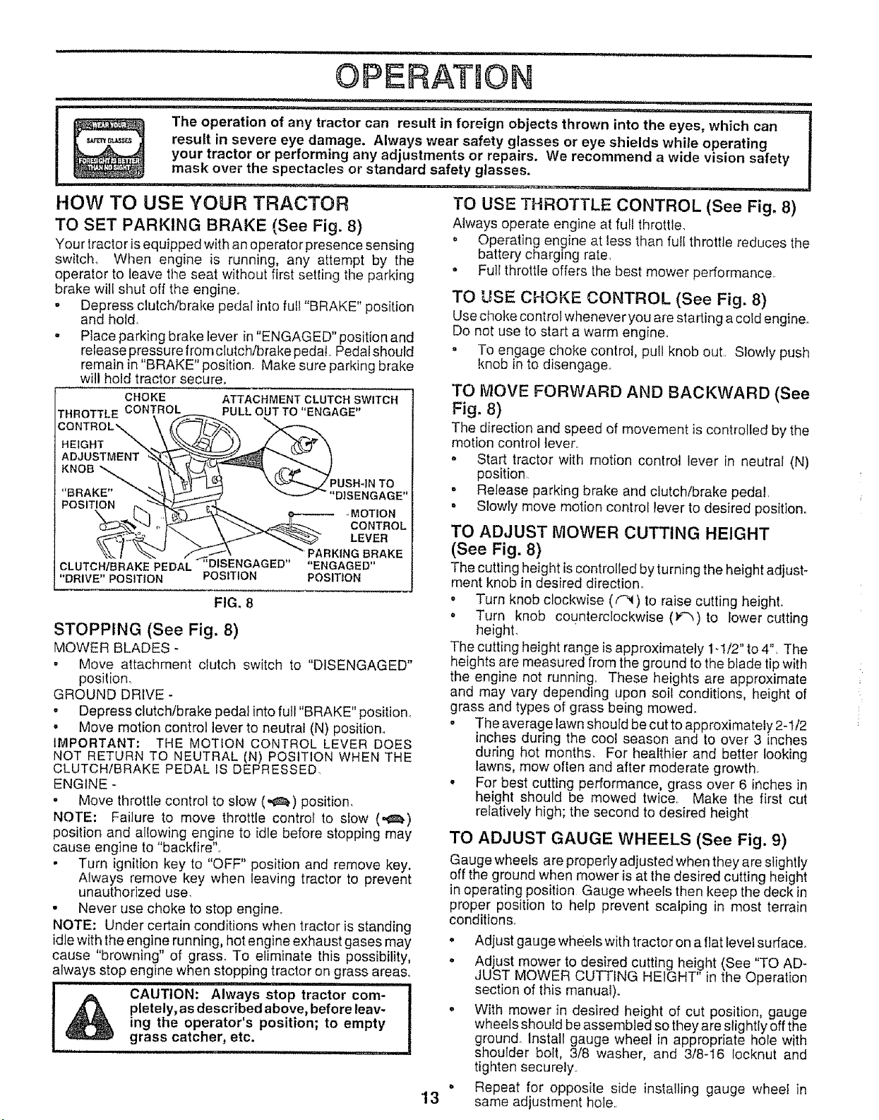
HOW TO USE YOUR TRACTOR
TO SET PARKING BRAKE (See Fig, 8)
Your tractor is equipped with an operator presence sensing
switch° When engine is running, any attempt by the
operator to leave the seat without first setting the parking
brake will shut off the engine_
° Depress clutch/brake pedal into full "BRAKE" position
and hotd_
• Place parking brake lever in "ENGAGED" position and
release pressure from clutch/brake pedal Pedal should
remain in"BRAKE" position. Make sure parking brake
will hold tractor secure.
CHOKE ATTACHMENT CLUTCH SWITCH
HROTTLE CONTROL PULL OUT TO "ENGAGE"
HEIGHT _'_.,._,_.,.,-'_2__J_,)_ {._>_""_
ADJUSTMENT _--'_-<_'__ _ I
KNOB "_ \_. _,__ r{_'@_'_
, _ \ \ '_- I_ ',..'_,_',-...._/PUSH-IN TO
' BRAKE" _'_'_ _'_ _ _ "DISENGAGE"
POSI N -'_ _"
T I__ LCMEOOv_T_#OL
k_ "'___ARK,N G BRAKE
CLUTCH/BRAKE PEDAL DISENGAGED ENGAGED
"DRIVE" POSIT!ON POSITION POSITION
......... ,,,........ , ........ i._rii_ , , ", ,, ,,,. ,,
The operation of any tractor can result in foreign objects thrown into the eyes, which can
result in severe eye damage. Always wear safety glasses or eye shields while operating
your tractor or performing any adjustments or repairs. We recommend a wide vision safety
mask over the spectacles or standard safety glasses.
TO USE THROTTLE CONTROL (See Fig. 8)
Always operate engine at full throttle.
o Operating engine at less than fult throttle reduces the
battery charging rate
o Full throttle offers the best mower performance_
FIG. 8
STOPPING (See Fig. 8)
MOWER BLADES -
• Move attachment clutch switch to "DISENGAGED"
position_
GROUND DRIVE -
,, Depress clutch/brake pedal into full "BRAKE" position
• Move motion control lever to neutral (N) position.
IMPORTANT: THE MOTION CONTROL LEVER DOES
NOT RETURN TO NEUTRAL (N) POSITION WHEN THE
CLUTCH/BRAKE PEDAL IS DEPRESSED.
ENGINE -
• Move throttle control to slow (,,,_) position.
NOTE: Failure to move throttle control to slow (,_)
position and allowing engine to idle before stopping may
cause engine to "backfire".
• Turn ignition key to "OFF" position and remove key.
Always remove key when leaving tractor to prevent
unauthorized use,
° Never use choke to stop engine°
NOTE: Under certain conditions when tractor is standing
idle with the engine running, hot engine exhaust gases may
cause "browning" of grass_ To eliminate this possibility,
always stop engine when stopping tractor on grass areas.
CAUTION: Always stop tractor com-
pletely, as described above, before leav-
ing the operator's position; to empty
grass catcher, etc.
.11,.i i .i,m,,i,ii i
TO USE CHOKE CONTROL (See Fig. 8)
Use choke control whenever you are starting acold engine°
Do not use to start a warm engine.
= To engage choke control, pull knob out Slowly push
knob in to disengage.
TO MOVE FORWARD AND BACKWARD (See
Fig. 8)
The direction and speed of movement is controlled by the
motion control lever
o Start tractor with motion control lever in neutral (N)
position
= Release parking brake and clutch/brake pedal
o Slowly move motion control lever to desired position°
TO ADJUST MOWER CUTTING HEIGHT
(See Fig. 8)
The cutting height is controlled by turning the height adjust-
merit knob in desired direction°
. Turn knob clockwise (f_) to raise cutting heighL
- Turn knob counterclockwise (_)to lower cutting
height.
The cutting height range is approximately ld/2" to 4". The
heights are measured from the ground to the blade tip with
the engine not running. These heights are approximate
and may vary depending upon soil conditions, height of
grass and types of grass being mowed°
o The average lawn should be cut to approximately 2-1/2
inches during the cool season and to over 3 inches
during hot months. For healthier and better looking
lawns, mow often and after moderate growth.
o For best cutting performance, grass over 6 inches in
height should be mowed twtce Make the first cut
relatively high; the second to desired height
13
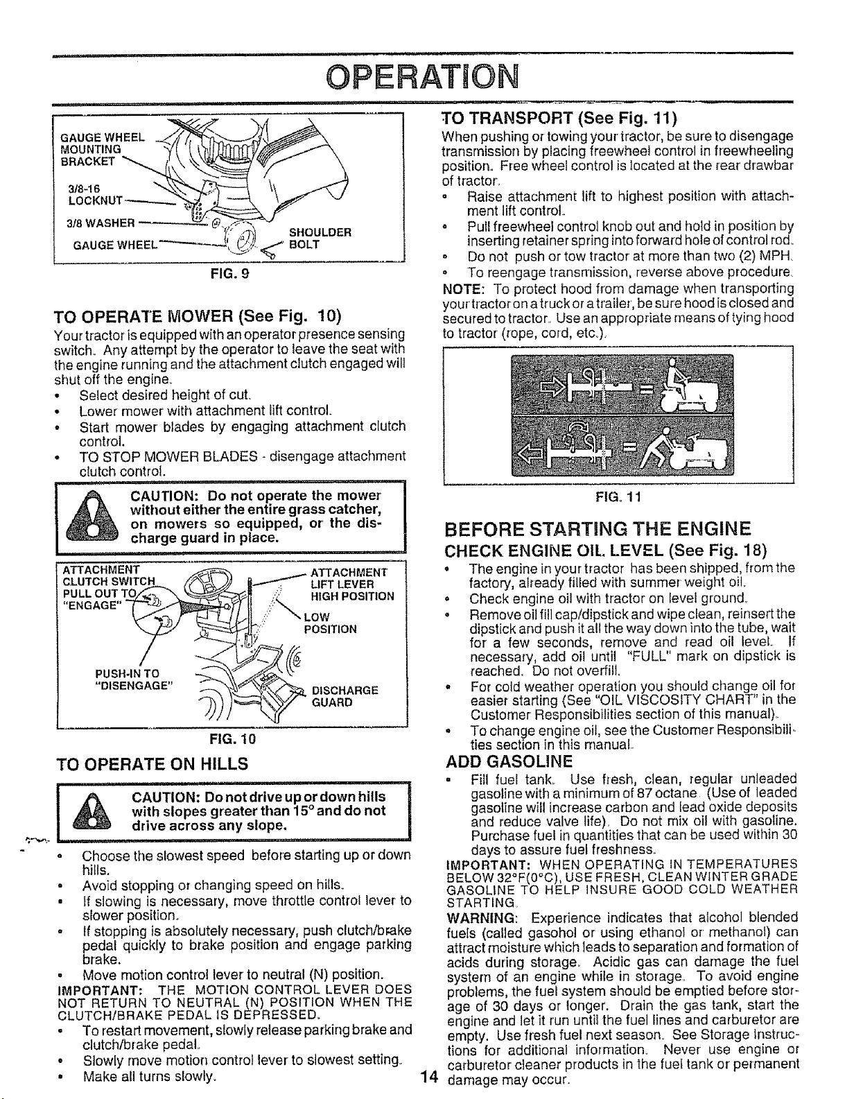
TO ADJUST GAUGE WHEELS (See Fig. 9)
Gauge wheels are properly adjusted when theyare slightly
off the ground when mower isat the desired cutting height
in operating position Gauge wheels then keep the deck in
proper position to help prevent scalping in most terrain
conditions.
• Adjust gauge wheels with tractor on a flat level surface.
• Adjust mower to desired cutting height (See "TO AD-
JUST MOWER CUTTING HEIGHT" in the Operation
section of this manual).
o With mower in desired height of cut position, gauge
wheels should be assembled so they are slightly off the
ground. Install gauge wheel in appropriate hole with
shoulder bolt, 3/8 washer, and 3/8-I6 Iocknut and
tighten securely
• Repeat for opposite side installing gauge wheet in
same adjustment hole.
iil,lllllllli, iii iiiiiiii i iiiiii1,1,111 • •
OPERATION
........................ i ,,, i 'N
GAUGE WHEEL
MOUNTING
BRACKET
3/8-!6
LOCKNUT---------
3/8 WASHER
GAUGE WHEEL'
SHOULDER
BOLT
FIG. 9
TO OPERATE MOWER (See Fig. 10)
Your tractor is equipped with an operator presence sensing
switch_ Any attempt by the operator to leave the seat with
the engine running and the attachment clutch engaged will
shut off the engine.
• Select desired height of cut.
• Lower mower with attachment lift control.
• Start mower blades by engaging attachment clutch
control
• TO STOP MOWER BLADES - disengage attachment
clutch control.
CAUTION: Do not operate the mower
without either the entire grass catcher,
on mowers so equipped, or' the dis-
charge guard in place.
........................ [
ATTACHMENT _ ATTACHMENT
CLUTCH SWITCH iY_ _._ _..,_p-"_ LIFT LEVER
PUSH IN TO --.. \"
"DISENGAGE" "_'\_\ fTk'_"/_ DISCHARGE
FIG. 10
TO OPERATE ON HILLS
! A CAUTION: Do not drive up or down hills !
I _ with slopes greater than 15° and do not
i
..._ I _ drive across any slope,
Ili ,i i, ilii,lii,llii i i
• Choose the slowest speed before starting up or down
hills.
° Avoid stopping or changing speed on hills.
• If slowing is necessary, move throttle control lever to
slower position°
° If stopping is absolutely necessary, push clutch/brake
pedal quickly to brake position and engage parking
brake,
• Move motion control lever to neutral (N) position.
IMPORTANT: THE MOTION CONTROL LEVER DOES
NOT RETURN TO NEUTRAL (N) POSITION WHEN THE
CLUTCH/BRAKE PEDAL 1SDEPRESSED.
. To restart movement, slowly release parking brake and
clutch/brake pedal
• Stowly move motion control lever to slowest setting.
• Make all turns slowly.
14
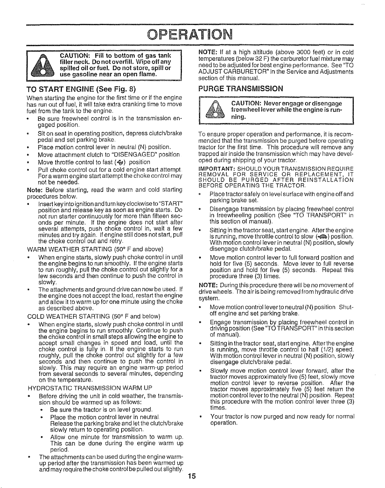
TO TRANSPORT (See Fig. 11)
When pushing or towing your tractor, be sure to disengage
transrnission by placing freewheel control in freewheeling
position, Free wheel control is located at the rear drawbar
of tractor',
• Raise attachment lift to highest position with attach-
ment lift control,
- Pull freewheel control knob out and hold in position by
inserting retainer spring intoforward hole of control rod
= Do not push or tow tractor at more than two (2) MPH
° To reengage transmission, reverse above procedure
NOTE: To protect hood from damage when transporting
your tractor on a truck or a trailer, be sure hood isclosed and
secured to tractor, Use an appropriate means of tying hood
to tractor (rope, cord, etc.).
FIGo 11
BEFORE STARTING THE ENGINE
CHECK ENGINE OIL LEVEL (See Fig. 18)
° The engine in your tractor has been shipped, from the
factory, already filled with summer weight oil
. Check engine oil with tractor on Ieve{ ground_
o Remove oil fill cap/dipstick and wipe clean, reinsert the
dipstick and push itall the way down into the tube, wait
for a few seconds, remove and read oil level If
necessary, add oil until "FULL" mark on dipstick is
reached. Do not overfill
° For cold weather operation you should change oil for
easier starting (See "OIL VISCOSITY CHART" in the
Customer Responsibilities section of this manual)
• To change engine oil, see the Customer Responsibilio
ties section in this manual
ADD GASOLINE
• Fill fuel tank,, Use fresh, clean, regular unleaded
gasoline with a minimum of 87 octane (Use of leaded
gasoline will increase carbon and lead oxide deposits
and reduce valve life), Do not mix oil with gasoline.
Purchase fuel in quantities that can be used within 30
days to assure fuel freshness
IMPORTANT: WHEN OPERATING IN TEMPERATURES
BELOW 32°F(0°C), USE FRESH, CLEAN WINTER GRADE
GASOLINE TO HELP iNSURE GOOD COLD WEATHER
STARTING,
WARNING: Experience indicates that alcohol blended
fuets (called gasohol or' using ethanol or methanol) can
attract moisture which leads to separation and formation of
acids during storage. Acidic gas can damage the fuel
system of an engine while in storage° To avoid engine
problems, the fuef system should be emptied before stor-
age of 30 days or longer. Drain the gas tank, start the
engine and let it run until the fuel lines and carburetor are
empty. Use fresh fuel next season, See Storage Instruc-
tions for additional information. Never use engine or
carburetor cleaner products in the fuel tank or permanent
damage may occur,
] ,_,_. filler neck. Do not overfill. Wipeoffany
,_ spilled oil or fuel. Do not store, spill or
I _ use gasoline near an open flame.
TO START ENGINE (See Fig. 8)
When starting the engine for the first time or if the engine
has run out of fuel, itwill take extra cranking time to move
fuel from the tank to the engine°
. Be sure freewheel control is in the transmission en-
gaged position..
• Sit on seat in operating position, depress clutch/brake
pedal and set parking brake.
° Ptace motion control lever in neutral (N) position.
• Move attachment clutch to "DISENGAGED" position
o Move throttle control to fast (,¢_) position
• Pull choke control out for a cold engine start attempt
For a warm engine start attempt the choke control may
not be needed.
Note: Before starting, read the warm and cold starting
procedures below.
° Insert key into ignition and turn key clockwise to"START"
position and release key as soon as engine starts. Do
not run starter continuously for more than fifteen sec-
onds per minute.. If the engine does not start after
several attempts, push choke control in, wait a few
minutes and try again, tfengine still does not start, pull
the choke control out and retry..
WARM WEATHER STARTING (50 ° F and above)
o When engine starts, slowly push choke control in until
the engine begins to run smoothly. If the engine starts
to run roughly, pull the choke control out slightly for a
few seconds and then continue to push the control in
slowly.
o The attachments and ground drive can now be used. If
the engine does not accept the load, restart the engine
and allow it to warm up for one minute using the choke
as described above.
COLD WEATHER STARTING (50° F and below)
• When engine starts, slowly push choke control in until
the engine begins to run smoothly. Continue to push
the choke control in small steps allowing the engine to
accept small changes in speed and load, until the
choke control is fully in. If the engine starts to run
roughly, pull the choke control out slightly for a few
seconds and then continue to push the control in
slowly. This may require an engine warm-up period
from several seconds to several minutes, depending
on the temperature_
HYDROSTATIC TRANSMISSION WARM UP
• Before driving the unit in cold weather, the transmis-
sion should be warmed up as follows:
o Be sure the tractor is on level ground.
• Place the motion control lever in neutral.
Release the parking brake and let the clutch/brake
slowly return to operating position.
o Allow one minute for transmission to warm up..
This can be done during the engine warm up
period.
- The attachments can be used during the engine warm-
up period after the transmission has been warmed up
and may require the choke control bepulled out slightly.
i ..................
NOTE; If at a high altitude (above 3000 feet) or in cold
temperatures (below 32 F) the carburetor fuel mixture may
need to be adjusted for best engine performance. See "TO
ADJUST CARBURETOR" in the Service and Adjustments
section of this manual.
PURGE TRANSMISSION
'__'---CAUTION:Neve__r engageor disengag_
freewheel lever while the engine is run-
To ensure proper operation and performance, it is recom-
mended that tile transmission be purged before operating
tractor for the first time. This procedure will remove any
trapped air inside the transmission which may have devel-
oped during shipping of your tractor.
IMPORTANT: SHOULD YOUR TRANSMISSION REQUIRE
REMOVAL FOR SERVICE OR REPLACEMENT, tT
SHOULD BE PURGED AFTER REINSTALLATION
BEFORE OPERATING THE TRACTOR,
o Place tractor safely on level surface with engine off and
parking brake set°
o Disengage transmission by placing freewheel control
in freewheeling position (See "TO TRANSPORT" in
this section of manual)
. Sitting in the tractor seat, start engineo After the engine
isrunning, move throttle control to slow (,,,_) position..
With motion control lever in neutral (N) position, slowly
disengage ciutchtbrake pedal°
o Move motion control lever to full forward position and
hold for five (5) seconds. Move lever to full reverse
position and hold for five (5) seconds. Repeat this
procedure three (3) times.
NOTE: During this procedure there will be no movement of
drive wheels. The air isbeing removed from hydraulic drive
system°
o Move motion control leverto neutral (N) position Shut-
off engine and set parking brake.
• Engage transmission by placing freewheel control in
driving position (See "TO TRANSPORT" in this seclion
of manual).,
° Sitting in the tractor seat, start engine. After the engine
is running, move throttle control to half (112) speed.
With motion control lever inneutral (N) position, slowly
disengage clutch/brake pedal.
o Slowly move motion control lever forward, after the
tractor moves approximately five (5) feet, slowly move
motion control lever to reverse position. After the
tractor moves approximately five (5) feet return the
motion control lever tothe neutral (N) position. Repeat
this procedure with the motion control lever three (3)
times.
. Your tractor is now purged and now ready for normal
operation,.
15
OPERATION
MOWING TiPS
• Tire chainscannot be used when the mower housingis
attached to tractor,_
• Mower should be properly leveled for best mowing
performance.. See "TO LEVEL MOWER HOUSING" in
the Service and Adjustments section of this manual
o The left hand side of mower should be used for trim-
ming.
= Drive so that clippings are discharged onto the area
that has been cut. Have the cut area to the rightof the
machine_ This will result in a more eve'n distribution of
clippings and more uniform cutting,
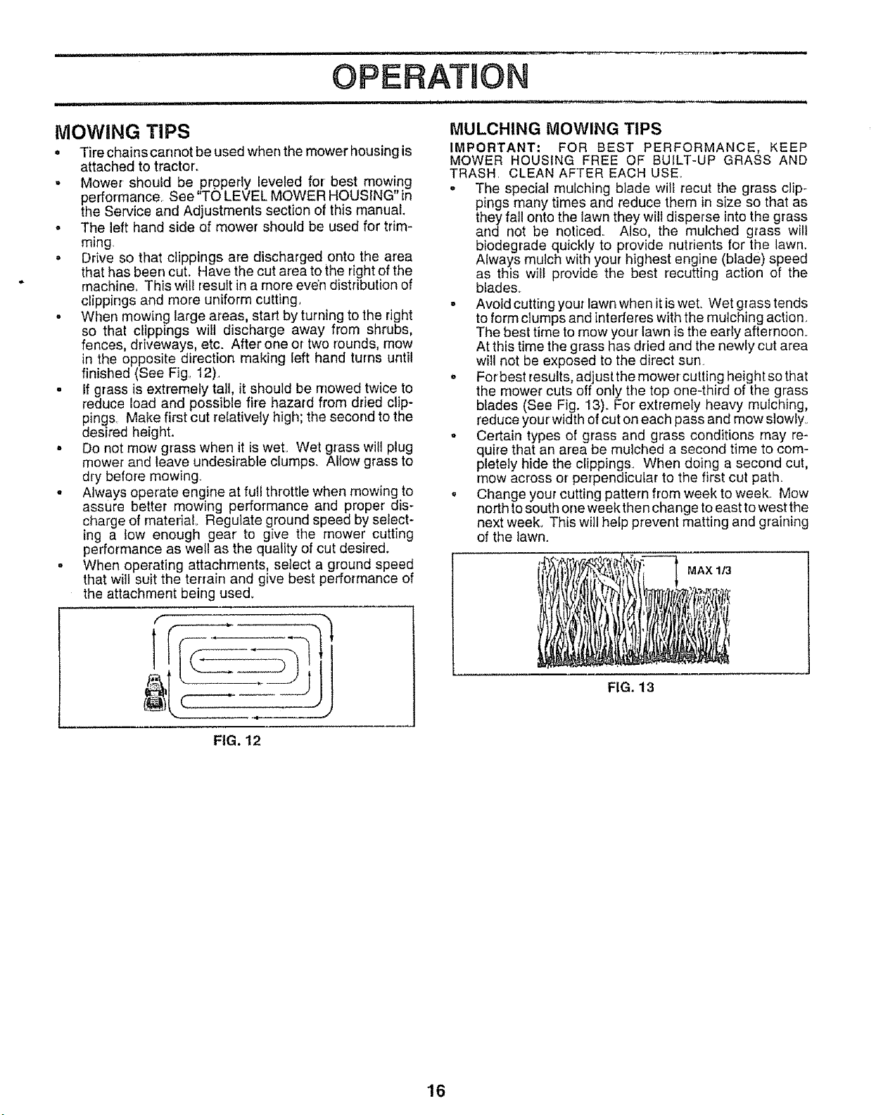
. When mowing large areas, start by turning to the right
so that clippings will discharge away from shrubs,
fences, driveways, etc. After one or two rounds, mow
in the opposite direction making left hand turns until
finished (See Fig_12),
. If grass is extremely tall, it should be mowed twice to
reduce load and possible fire hazard from dried clip-
pings, Make first cut relatively high; the second to the
desired height.
• Do not mow grass when it iswet, Wet grass will plug
mower and leave undesirable clumps. Allow grass to
dry before mowing_
• Always operate engine at full throttle when mowing to
assure better mowing performance and proper dis-
charge of material Regulate ground speed by select-
ing a low enough gear to give the mower cutting
performance as well as the quality of cut desired.
= When operating attachments, select a ground speed
that will suit the terrain and give best performance of
the attachment being used.
MULCHING MOWING TIPS
IMPORTANT; FOR BEST PERFORMANCE, KEEP
MOWER HOUSING FREE OF BUILT-UP GRASS AND
TRASH. CLEAN AFTER EACH USE.
- The special mulching blade will recut the grass clip-
pings many times and reduce them in size so that as
they fall onto the lawn they will disperse intothe grass
and not be noticed., Also, the mulched grass will
biodegrade quickly to provide nutrients for the lawn.
Always mulch with your highest engine (blade) speed
as this wilt provide the best recutting action of the
blades°
o Avoid cutting your lawn when it is wet. Wet grass tends
to form clumps and interferes with the mulching action.
The best time to mow your lawn is the early afternoon.
At this time the grass has dried and the newly cut area
will not be exposed to the direct sun
,, For best results, adjust the mower cutting height so that
the mower cuts off only the top one-third of the grass
blades (See Fig. 13). For'extremely heavy mulching,
reduce your width of cut on each pass and mow slowly°
- Certain types of grass and grass conditions may re-
quire that an area be mulched a second time to com-
pletely hide the clippings. When doing a second cut,
mow across or perpendicular to the first cut path_
, Change your cutting pattern from week to week.. Mow
north tosouth one week then change to east to west the
next week. This will hetp prevent matting and graining
of the lawn.
MAX 113
FIG. 13
FIG. 12
16
..... ,i,,,_,_ _ ......'"' ' i,u,,,,i,,,,,,,,,i,,ii,, i .... i1,,, i
CUSTOMER RESPONS BBLUTnES
,11,, , _ .......................... ii, ¸ i u , ,........
MAINTENANC'E SCH"EDULE "4_'_ __ _D
FILL,NDATES
ASYOUCOMPL E
REGULAR SERVICE ..................................f_.f- <¢4,_/_-4_..f_ __?_
/_-,"./ _-7.,"_-C ATES
CheckBrakeOperation _ _ .............. .......
CheckTire Pressure
T CheckforLoose Fasteners
R '""'S'l_'a';p'entRepfaceMowerBlades
C LubricationCha"
T Check Battery Level/Recha!ge .....
0 CleanBatteryandTerminals
R CheckTransaxteCoottng
Adjust Blade Belt(s) Tension
AdjustMotionDriveBelt(s)Tension
CheckEngineOil Level 6#4
ChangeEngineO1_
E ,,C!,ean,AirFilter
,,6*4
......V;,,,.....¢
v'
...... _,_ II1_'_
N CteanAir Screen
G InspectMuffler/SparkAttester if
J Replace Oil Filter (If equipped) Q4_1,2 ..........
N ....
Clean Engln,e,O,ooli,ng Fills , 6#42
,Replao_SparkPl,_ _"' _ .....
Replace Air Filter Paper Cartridge _42 .........
ReplaceFuelFilter E_#' "
1 - Change more often when operating under a heavy load or in high ambient temperatures
2., Service more often when operating in dirty or dusty conditions
3 - If equipped with oil filler, change oil every 50 hours
4 - Replace blades more ellen when mowing tnsandy soil
5 - If equipped with ad_uslable system
6 - Not requited if equipped with maintenance4ree battery
7 _Tighlen frost axle pivot belt to 35 ft -Ibe maximum
Do not oveltlghten,
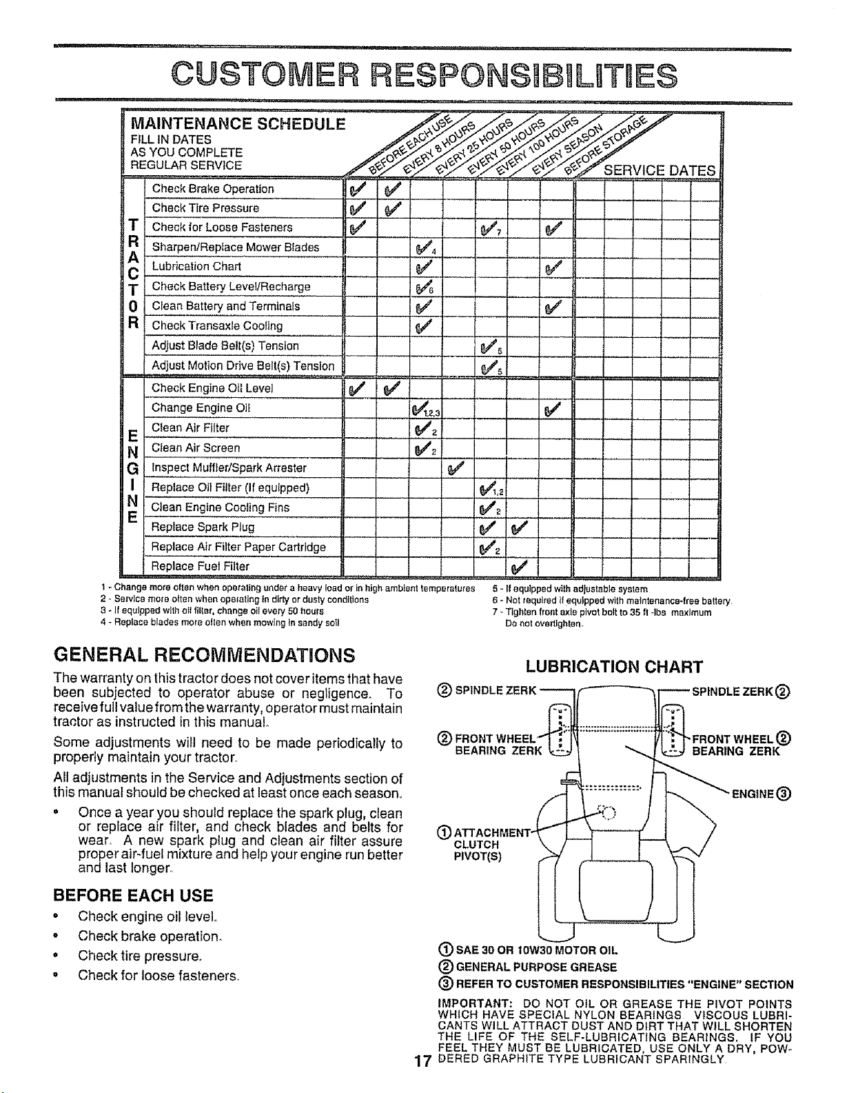
GENERAL RECOMMENDATIONS
The warranty on this tractor does not cover items that have
been subjected to operator abuse or negligence. To
receive full value from the warranty, operator must maintain
tractor as instructed in this manual.
Some adjustments will need to be made periodically to
properly maintain your tracton
All adjustments in the Service and Adjustments section of
this manual should be checked at least once each season,,
• Once a year you should replace the spark plug, clean
or replace air filter, and check blades and belts for
wear, A new spark plug and clean air filter assure
proper air-fuel mixture and help your engine run better
and last longer.
LUBRICATION CHART
®
(_) FRONT
BEARING ZERK
(_) CLUTCH
PIVOT(S)
®
"FRONT WHEEL (_)
BEARINGZERK
ENGtNE(_)
BEFORE EACH USE
° Check engine oil level°
° Check brake operation.
o Check tire pressure.
. Check for loose fasteners.
(_) SAE 30 OR 10W30 MOTOR OIL
® GENERAL PURPOSE GREASE
(_) REFER TO CUSTOMER RESPONSIBILITIES "ENGINE" SECTION
IMPORTANT: DO NOT OIL OR GREASE THE PIVOT POINTS
WHICH HAVE SPECIAL NYLON BEARINGS VISCOUS LUBRI-
CANTS WILL ATTRACT DUST AND DIRT THAT WILL SHORTEN
THE LIFE OF THE SELF-LUBRICATING BEARINGS. IF YOU
FEEL THEY MUST BE LUBRICATED, USE ONLY A DRY, POW-
17 DERED GRAPHITE TYPE LUBRICANT SPARINGLY

CUSTO RESPONSIBILITIES
TRACTOR
Always observe safety rules when performing any mainte-
nance,
BRAKE OPERATION
iftractor requires more than six (6) feet stopping distance
at high speed in highest gear, then brake must be adjusted.
(See "TO ADJUST BRAKE" in the Service and Adjust-
ments section of this manual).
TIRES
o Maintain proper air pressure in all tires (See "PROD-
UCT SPECIFICATIONS" on page 3 of this manual).
• Keep tires free of gasoline, oil, or insectcontrol chemi-
cals which can harm rubber.
• Avoid stumps, stones, deep ruts, sharp objects and
other hazards that may cause tire damage.
NOTE: To seal tire punctures and prevent flat tires due to
slow leaks, tire sealant may be purchased from your local
parts dealer. Tire sealant also prevents tire dry rot and
corrosion,
BLADE CARE
For best results mower blades must be kept sharp. Re-
place bent or damaged blades.
TO SHARPEN BLADE (See Fig, 15)
Care should be taken to keep the blade balanced. An
unbalanced blade will cause excessive vibration and even-
tual damage to mower and engine.
• The blade can be sharpened with a file or on a grinding
wheel.. Do not attempt to sharpen while on the mower.
• To check blade balance, you will need a 5/8" diameter
steel bolt, pin, or a cone balancer_ (When using a cone
balancer, follow the instructions supplied with bal-
ancer.)
o Slide blade onto an unthreaded portion of the steel bolt
or pin and hold the bolt or pin pala!iel with the ground.
If blade is balanced, it should remain in a horizontal
position. If either end of the blade moves downward,
sharpen the heavy end until the blade is balanced.
NOTE: Do not use a nail for balancing blade. The lobes of
the center hole may appear' to be centered, but are not..
CENTER HOLE / //
/
/ /
518" BOLT
BLADE
BLADE REMOVAL (See Fig, 14)
• Raise mower to highest position to allow access to
blades..
• Remove hex bolt, lock washer and flat washer securing
blade..
o Install new or resharpened blade with trailing edge up
towards deck as shown.
• Reassemble hex bolt, lock washer and ftat washer in
exact order as shown.
. Tighter] bolt securely (30-35 Ft. Lbs. torque).
IMPORTANT: BLADE BOLT ISGRADE 8 HEATTREATEDo
NOTE= We do not recommend sharpening blade- but ifyou
do, be sure the blade is balanced,
BLADEx __
TRAILING EDGE
LATWA=HER Z
L__
_" HEX BOLT (GRADE 8)*
*A GRADE 8 HEAT TREATED BOLT CAN BE
IDENTIFIED BY SIX LINES ON THE BOLT HEAD.
FIG. 15
BATI'ERY
Your tractor has a battery charging system which is suffi-
cient for normal use. However, periodic charging of the
battery with an automotive charger will extend its life.,
. Keep battery and terminals clean.
° Keep battery bolts tighL
° Keep small vent holes open,
o Recharge at 6-10 amperes for 1 hour.
TO CLEAN BATTERY AND TERMINALS
Corrosion and dirt on the battery and terminals can cause
the battery to "leak" power.
• Remove terminal guard.
• Disconnect BLACK battery cable first then RED
battery cable and remove battery from tractor.
• Rinse the battery with plain water and dry,
• Clean terminals and battery cable ends with wire brush
until bright..
• Coat terminals with grease or petroleum jelly,
• Reinstall battery (See "CONNECT BATTERY" in the
Assembly section of this manual).
FIG. 14
18
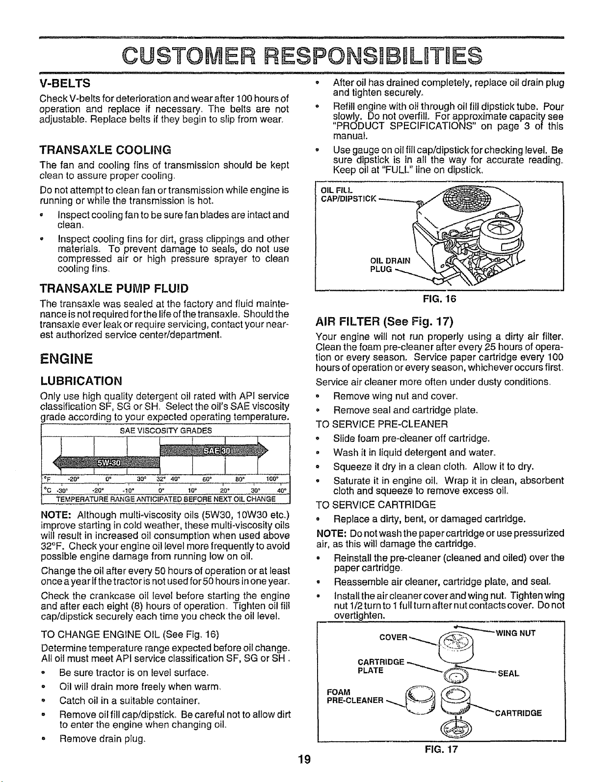
V-BELTS
Check V-belts for deterioration and wear after 100 hours of
operation and replace if necessary. The belts are not
adjustable. Replace belts ifthey begin to slip from wear.
TRANSAXLE COOLING
The fan and cooting fins of transmission should be kept
clean to assure proper cooling,
Do not attempt to clean fan or transmission while engine is
running or while the transmission is hot.
• Inspect cooling fan to be sure fan blades are intactand
clean,
° Inspect cooling fins for dirt, grass clippings and other
materials. To prevent damage to seals, do not use
compressed air or high pressure sprayer to clean
cooling fins.
TRANSAXLE PUMP FLUID
The transaxle was sealed at the factory and fluid mainte-
nance is not required for the life of the transaxle, Should the
transaxle ever leak or require servicing, contact your near-
est authorized service center/department°
ENGINE
LUBRICATION
Only use high quality detergent oil rated with API service
classification SF, SG or SH_ Select the oil's SAE viscosity
grade according to your expected operating temperature,
SAE VISCOSITY GRADES
_F -20 ° 0_ 30 _ 32" 40" 60 _ 80 _ 100 _
_c,._'oo .2oo .lo° o° lo. _o• 30° 40°
TEMPERATURE RANGE ANTICIPATED BEFORE NEXT OiL CHANGE _=.,=
NOTE: Although multi-viscosity oils (5W30, 10W30 etco)
improve starting in cold weather, these multi-viscosity oils
will result in increased oil consumption when used above
32°F. Check your engine oil [evet more frequently to avoid
possibte engine damage from running tow on oil.
Change the oil after every 50 hours of operation or at least
once ayear ifthe tractor isnot used for 50 hours inone year.
Check the crankcase oil level before starting the engine
and after each eight (8) hours of operation Tighten oil fill
cap/dipstick securely each time you check the oil level.
TO CHANGE ENGINE OIL (See Fig. 16)
Determine temperature range expected before oil change.
All oil must meet API service classification SF, SG or SHo
• Be sure tractor ison level surface.
o Oil wil! drain more freely when warm,
° Catch oil in a suitable container.
° Remove oil fill cap/dipstick1 Be careful not to allow dirt
to enter the engine when changing oil,
° Remove drain pIug.
_1,,,,,,,,1,1,, , i.......................... ,....................
= After oil has drained completely, replace oil drain plug
and tighten securely.
o Reffil engine with oil through oil fill dipstick tube, Pour
slowly. Do not overfill. For approximate capacity see
"PRODUCT SPECIFICATIONS" on page 3 of this
manual.
o Use gauge on oil fitl cap/dipstick for checking level. Be
sure dipstick is in alt the way for accurate reading.
Keep oil at "FULL" line on dipstick,
OIL FiLL
OIL DRA|N
FIG. 16
AIR FILTER (See Fig. 17)
Your engine will not run properly using a dirty air filter,
Clean the foam pre-cleaner after every 25 hours of opera-
tion or every season. Service paper cartridge every 100
hours of operation or every season, whichever occurs first,
Service air cleaner more often under dusty conditions,
= Remove wing nut and cover,
o Remove seal and cartridge plate_
TO SERVICE PRE-CLEANER
o Slide foam pre-dleaner off cartridge.
o Wash it in liquid detergent and water.
o Squeeze it dry in a clean cloth. Allow it to dry.
o Saturate it in engine oil, Wrap it in clean, absorbent
cloth and squeeze to remove excess Oilo
TO SERVICE CARTRIDGE
o Replace a dirty, bent, or damaged cartridge.
NOTE" Do notwashthe paper cartridge or use pressurized
air, as this will damage the cartridge.
- Reinstall the pre-cteaner (cleaned and oiled) over the
paper cartridge_
o Reassemble air cleaner, cartridge plate, and seal
° Install the air cleaner cover and wing nut° Tighten wing
nut 1/2tumtol fuliturnafter nutcontactscover. Donot
overtighten.
FOAM
PRE-CLEANER _'_-_, _""-_'CARTRIDGE
@
FIG. 17
19
i, ii .................................. ---.
CUSTOMER RESPONSIBILITIES
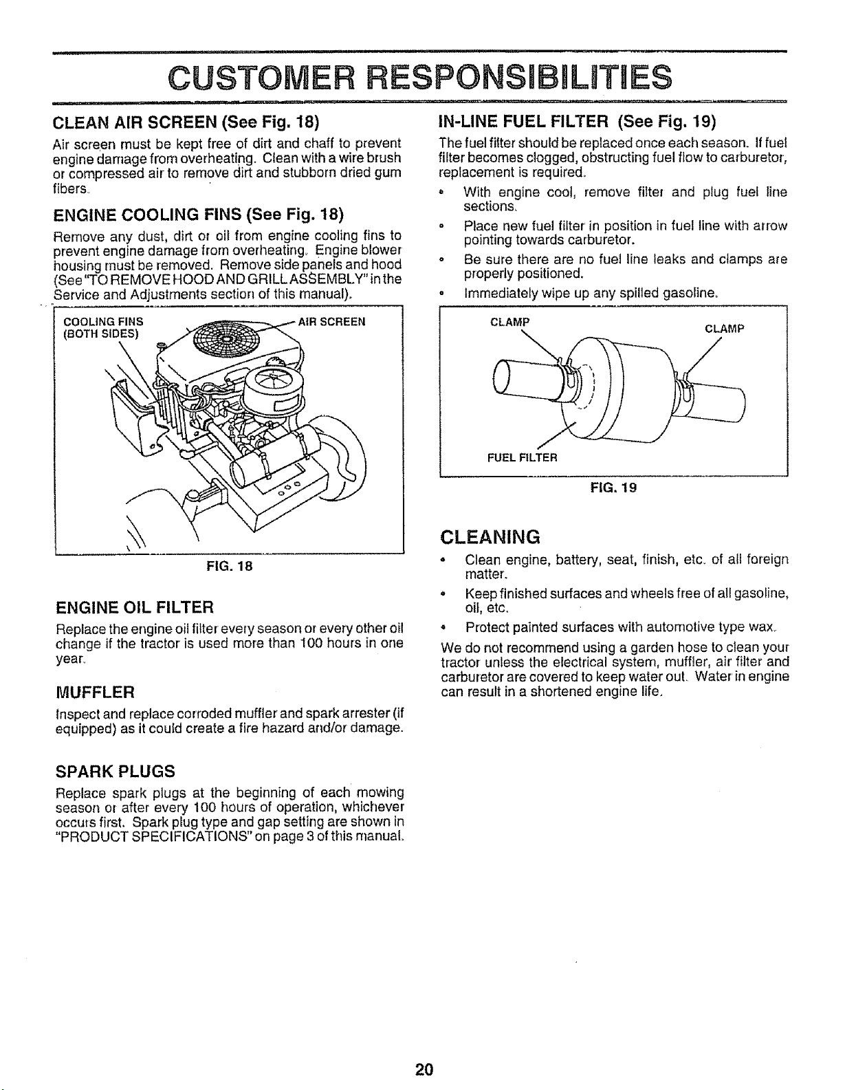
CLEAN AIR SCREEN (See Fig. 18)
Air screen must be kept free of dirt and chaff to prevent
engine damage from overheating. Ctean with a wire brush
or compressed air to remove dirt and stubborn dried gum
fibers
ENGINE COOLING FINS (See Fig. 18)
Rernove any dust, dirt or oil from engine cooling fins to
prevent engine damage from overheating. Engine blower
housing must be removed. Remove side panels and hood
(See"TO REMOVE HOOD AND GRILLASSEMBLY" inthe
Service and Adjustments section of this manual)..
IN-LINE FUEL FILTER (See Fig. 19)
The fuel fitter should be replaced once each season. Iffuel
filter becomes clogged, obstructing fuel flow to carburetor,
replacement is required..
o With engine coot, remove filter and plug fuel line
sections_
= Place new fuel filter in position in fuel line with arrow
pointing towards carburetor.
o Be sure there are no fuel line leaks and clamps are
properly positioned.
= Immediately wipe up any spilled gasoline_
COOLING FINS SCREEN
(BOTH SIDES)
\
FIG. 18
ENGINE OIL FILTER
Replace the engine oilfitterevery season or every other oil
change if the tractor is used more than 100 hours in one
year_
MUFFLER
inspect and replace corroded muffler and spark arrester (if
equipped) as itcoufd create a fire hazard and/or damage.
CLAMP
FUEL FILTER
FIG. 19
CLEANING
= Clean engine, battery, seat, finish, etc. of all foreign
matter.
o Keep finished surfaces and wheels free of all gasoline,
oil, etc.
o Protect painted surfaces with automotive type waxy.
We do not recommend using a garden hose to clean your
tractor unless the electrical system, muffler, air filter and
carburetor are covered to keep water out. Water inengine
can result in a shortened engine life.
SPARK PLUGS
Replace spark plugs at the beginning of each mowing
season or after every 100 hours of operation, whichever
occurs first. Spark plug type and gap setting are shown in
"PRODUCT SPECIFICATIONS" on page 3 of this manual
2O
,&
0
Q
+
i
TRACTOR
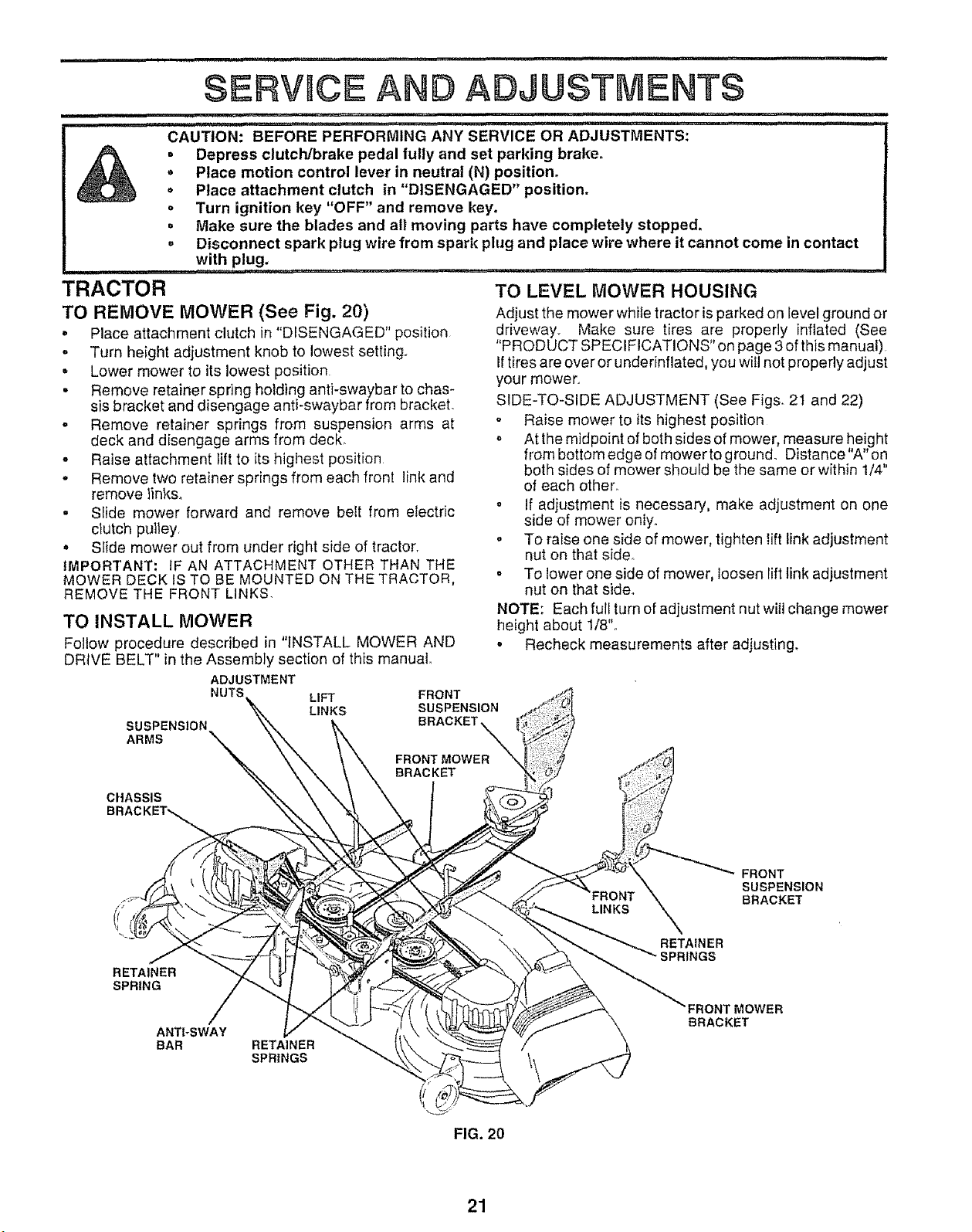
TO REMOVE MOWER (See Fig. 20)
° Place attachment clutch in "DISENGAGED" position
. Turn height adjustment knob to lowest setting+
• Lower mower to its lowest position
• Remove retainer spdng holding anti-swaybar to chas-
sis bracket and disengage anti-swaybar from bracket.
o Remove retainer springs from suspension arms at
deck and disengage arms from deck_
o Raise attachment lift to its highest position
,, Remove two retainer springs from each front linkand
remove links.
° Sfide mower forward and remove belt from electric
clutch pulley,
', Slide mower out from under right side of tractor+
IMPORTANT: IF AN ATTACHMENT OTHER THAN THE
MOWER DECK IS TO BE MOUNTED ON THE TRACTOR,
REMOVE THE FRONT LINKS.
SERVICE AND ADJUSTMENTS
.....::-:..... i.i...... IH ,11,1................................... i1,. i,.Ul._._. ,
........................ _ ,.......... u...1.
CAUTION: BEFORE PERFORMING ANY SERVICE OR ADJUSTMENTS:
. Depress clutch/brake pedal fully and set parking brake.
+ Place motion control lever in neutral (N) position.
,, Place attachment clutch in "DISENGAGED" position+
Turn ignition key "OFF" and remove key+
Make sure the blades and all moving parts have completely stopped.
Disconnect spark plug wire from spark plug and place wire where it cannot come in contact
with plug+
........................ .......1. _, .... N,.,.. ,...,,,,..
TO INSTALL MOWER
Follow procedure described in "INSTALL MOWER AND
DRIVE BELT" in the Assembly section of this manual
SUSPENSION
ARMS
TO LEVEL MOWER HOUSING
Adjust the mower white tractor is parked on level ground or
driveway., Make sure tires are properly inflated (See
"PRODUCT SPECIFICATIONS" on page 3 of this manual)
If tires are over or underinflated, you will not properly adjust
your mower+.
SIDE+TO-SIDE ADJUSTMENT (See Fig& 2I and 22)
* Raise mower to its highest position
o At the midpoint of both sides of mower, measure height
from bottom edge of mower to ground. Distance"A"on
both sides of mower should be the same or within 1/4"
of each other°
,' If adjustment is necessary, make adjustment on one
side of mower only+
° To raise one side of mower, tighten lift link adjustment
nut on that side+
o To lower one side of mower, loosen lift link adjustment
nut on that side+
NOTE: Each full turn of adjustment nut will change mower
height about 1/8"o
o Recheck measurements after adjusting+
ADJUSTMENT
NUT! LIFT
LINKS
FRONT
SUSPENSION
BRACKET
CHASSIS
FRONT
SUSPENSION
BRACKET
RETAINER
SPRING
ANTI+SWAY
BAR RETAINER
SPRINGS
RETAINER
SPRINGS
RONT MOWER
BRACKET
FIG. 20
21
==H 'HH'i Ir,,"TI
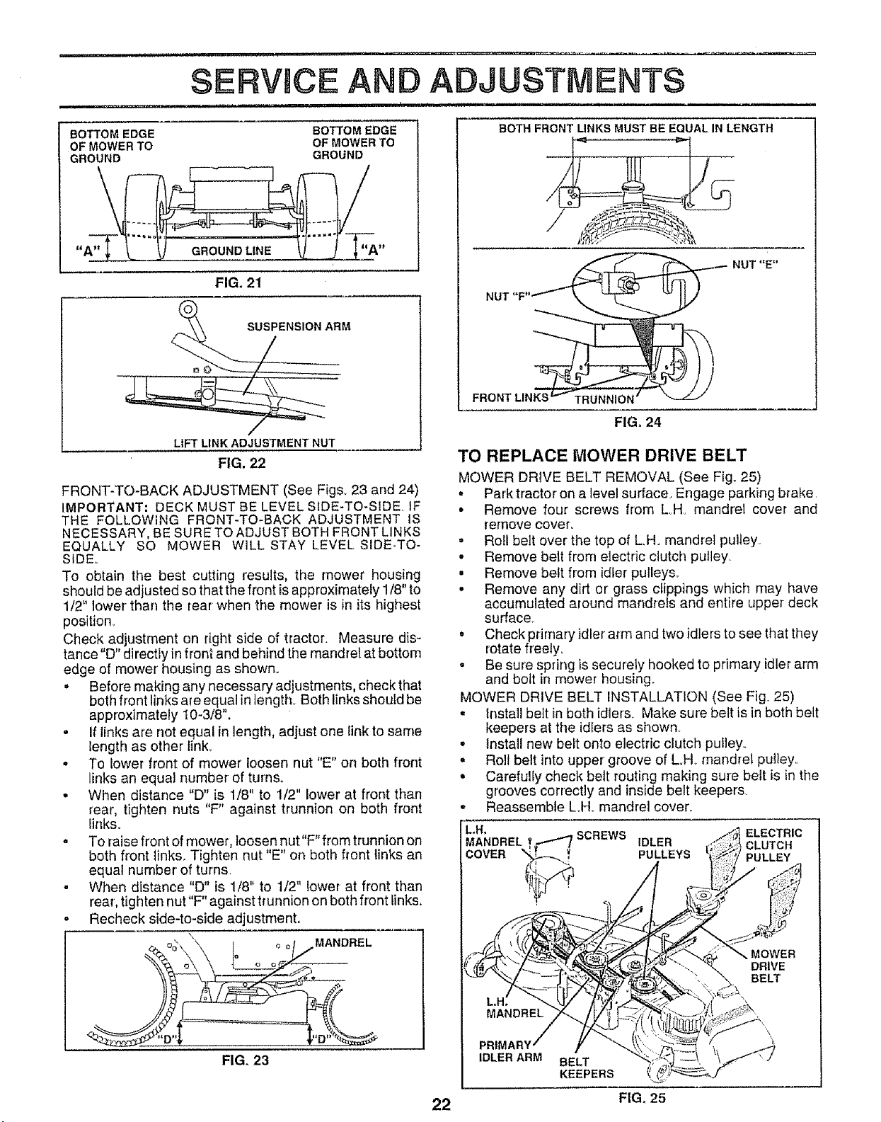
BOTTOM EDGE
OF MOWER TO
GROUND
GROUND LINE
FIG. 21
BOTTOM EDGE
OF MOWER TO
GROUND
LIFT LINK ADJUSTMENT NUT
FIG. 22
FRONT-TO-BACK ADJUSTMENT (See Figs,. 23 and 24)
IMPORTANT; DECK MUST BE LEVEL SIDE-TO-SIDE. IF
THE FOLLOWING FRONT-TO-BACK ADJUSTMENT IS
NECESSARY, BE SURE TO ADJUST BOTH FRONT LINKS
EQUALLY SO MOWER WILL STAY LEVEL SIDE-TO-
SIDE_
To obtain the best cutting results, the mower housing
should be adjusted so that the front isapproximately 1/8" to
1/2" lower than the rear when the mower is in its highest
position_
Check adjustment on right side of tractor. Measure dis-
tance "D" directly in front and behind the mandrel at bottom
edge of mower' housing as shown..
• Before making any necessary adjustments, check that
both front links are equal in lengthy Both links should be
approximately 10-3/8",
• If links are not equal in length, adjust one link to same
length as other link_
° To lower front of mower loosen nut "E" on both front
links an equal number of turns,
• When distance "D" is 1/8" to 1/2" lower at front than
rear, tighten nuts "F" against trunnion on both front
links_
, To raise front of mower, loosen nut"F"from trunnion on
both front links. Tighten nut "E" on both front links an
equal number of turns.
° When distance "D" is 1/8" to 1/2" lower at front than
rear, tighten nut"F" against trunnion on both front links,
- Recheck side-to-side adjustment.
MANDREL
FIG. 23
i ........................................................
ADJUSTMENTS
= 1, 111 = ...................
BOTH FRONT LINKS MUST BE EQUAL IN LENGTH
NUT "F"_ NUT "E"
FRONT LINKS _'_- TRUNNION _
FIG_24
TO REPLACE MOWER DRIVE BELT
MOWER DRIVE BELT REMOVAL (See Fig. 25)
° Park tractor on a level surface. Engage parking brake
• Remove four screws from LoHo mandrel cover and
remove cover°
• Roll belt over the top of L.Ho mandrel pulley..
- Remove belt from electric clutch pulley.
- Remove belt from idler pulleys_
• Remove any dirt or grass clippings which may have
accumulated around mandrels and entire upper deck
surface.
,, Check primary idler arm and two idlers to see that they
rotate freely=
• Be sure spring is securely hooked to prirnary idler'arm
and bolt in mower housing_
MOWER DRIVE BELT INSTALLATION (See Fig. 25)
• Install bett in both idlers. Make sure belt is in both belt
keepers at the idfers as shown.
• Install new belt onto electric clutch pulley.
° Roll belt into upper groove of L..H_mandrel pulley..
• Carefully check belt routing making sure belt is in the
grooves correctly and inside belt keepers.
,, Reassemble L.H. mandrel cover°
MOWER
DRIVE
BELT
PRIM
IDLER ARM
BELT
KEEPERS
22 FIG, 25
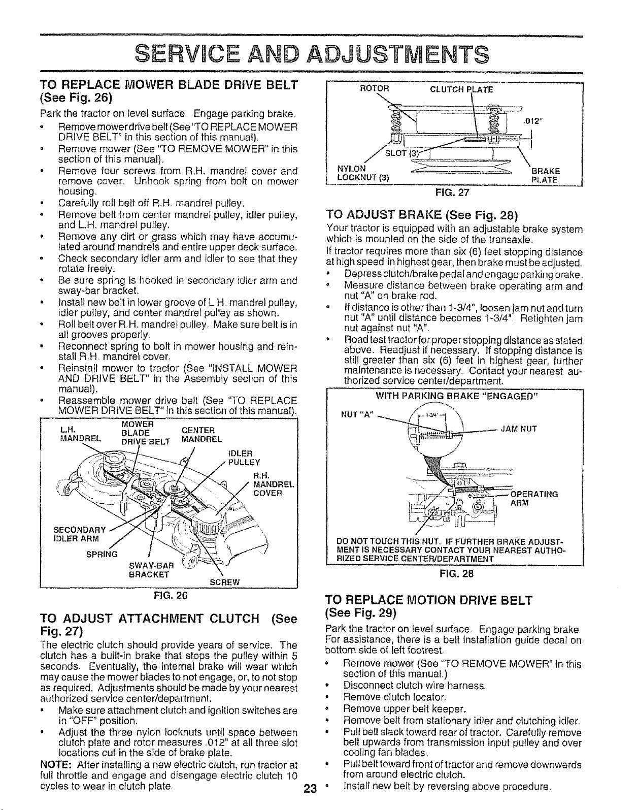
TO REPLACE MOWER BLADE DRIVE BELT
(See Fig. 26)
Park the tractor on level surface. Engage parking braker
• Remove mower drive belt (See'q"O REPLACE MOWER
DRIVE BELT" in this section of this manual).
° Remove mower (See "TO REMOVE MOWER" in this
section of this manual).
o Remove four screws from R_H, mandrel cover and
remove cover° Unhook spring from bolt on mower
housing,,
• Carefully rolt belt off RH, mandrel pulley,,
• Remove belt from center mandrel pulley, idler pulley,
and Loll. mandrel pultey,
o Remove any dirt or grass which rnay have accumu-
lated around mandrels and entire upper deck surface,,
• Check secondary idler arm and idler to see that they
rotate freely.
• Be sure spring is hooked in secondary idler arm and
sway-bar bracket,
° Install new belt in lower groove of LH,, mandrel pulley,
idler pulley, and center mandrel pulley as shown,
o Roll belt over R.H,,mandrel pulley_ Make sure belt is in
all grooves properly.
- Reconnect spring to bolt in mower housing and rein-
stall RH, mandrel cover.
• Reinstall mower to tractor (See "iNSTALL MOWER
AND DRIVE BELT" in the Assembly section of this
manual)°
. Reassemble mower drive belt (See "TO REPLACE
MOWER DRIVE BELT" inthis section of this manual),,
MOWER
L.H. BLADE CENTER
MANDREL DRIVE BELT MANDREL
_/ ,DLEB
, •.... .. RH.
SPRING
SWAY-BAR_._f_ _'f
ROTOR CLUTCH ELATE
NYLO ]BRAKE
LOCKNUT (3) PLATE
FIG. 27
TO ADJUST BRAKE (See Fig. 28)
Your tractor is equipped with an adjustable brake system
which is mounted on the side of the transaxfeo
If tractor requires more than six (6) feet stopping distance
at high speed inhighest gear, then brake must be adjusted,,
o
BRACKET SCREW
FIG. 26
TO ADJUST ATTACHMENT CLUTCH (See
Fig. 27)
The electric clutch should provide years of service. The
clutch has a built-in brake that stops the pulley within 5
Depress clutch/brake pedal and engage parking brake°
Measure distance between brake operating arm and
nut "A" on brake ro&
If distance is other than 1-3/4", loosen jam nut and turn
nut "A" until distance becomes 1-3/4", Retighten jam
nut against nut "A"_
Road test tractor for proper stopping distance as stated
above, Readjust if necessary. If stopping distance is
still greater than six (6) feet in highest gear, further
maintenance is necessary° Contact your nearest au*
thorized service center/department.
WITH PARKING BRAKE "ENGAGED"
seconds, Eventually, the internal brake will wear which
may cause the mower blades to not engage, or, to not stop
as required. Adjustments should be made by your nearest
authorized service center/department,
° Make sure attachment clutch and ignition switches are
in "OFF" position.
o Adjust the three nylon Iocknuts until space between
clutch plate and rotor measures .,012" at all three slot
locations cut in the side of brake plate.
NOTE: After installing a new electric clutch, run tractor at
full throttle and engage and disengage electric clutch 10
cycles to wear in clutch plate
o
23 °
NUT "A"
JAM NUT
ARM
NG
DO NOT TOUCH THIS NUT° IF FURTHER BRAKE ADJUST-
MENT IS NECESSARY CONTACT YOUR NEAREST AUTHO-
RIZED SERVICE CENTER/DEPARTMENT
FIG. 28
,, Remove mower (See "TO REMOVE MOWER" in this
section of this manual.)
o Disconnect clutch wire harness,.
• Remove clutch locatoro
• Remove upper belt keeper.
• Remove belt from stationary idler and clutching idler.
• Pull belt slack toward rear o! tractor. Carefully remove
belt upwards from transmission input pulley and over
cooling fan blades,,
Pull belt toward front of tracto r and remove downwards
from around electric clutch.
Install new belt by reversing above procedure,
TO REPLACE MOTION DRIVE BELT
(See Fig. 29)
Park the tractor on level surface, Engage parking brake
For assistance, there is a belt installation guide decal on
bottom side of left footrest°
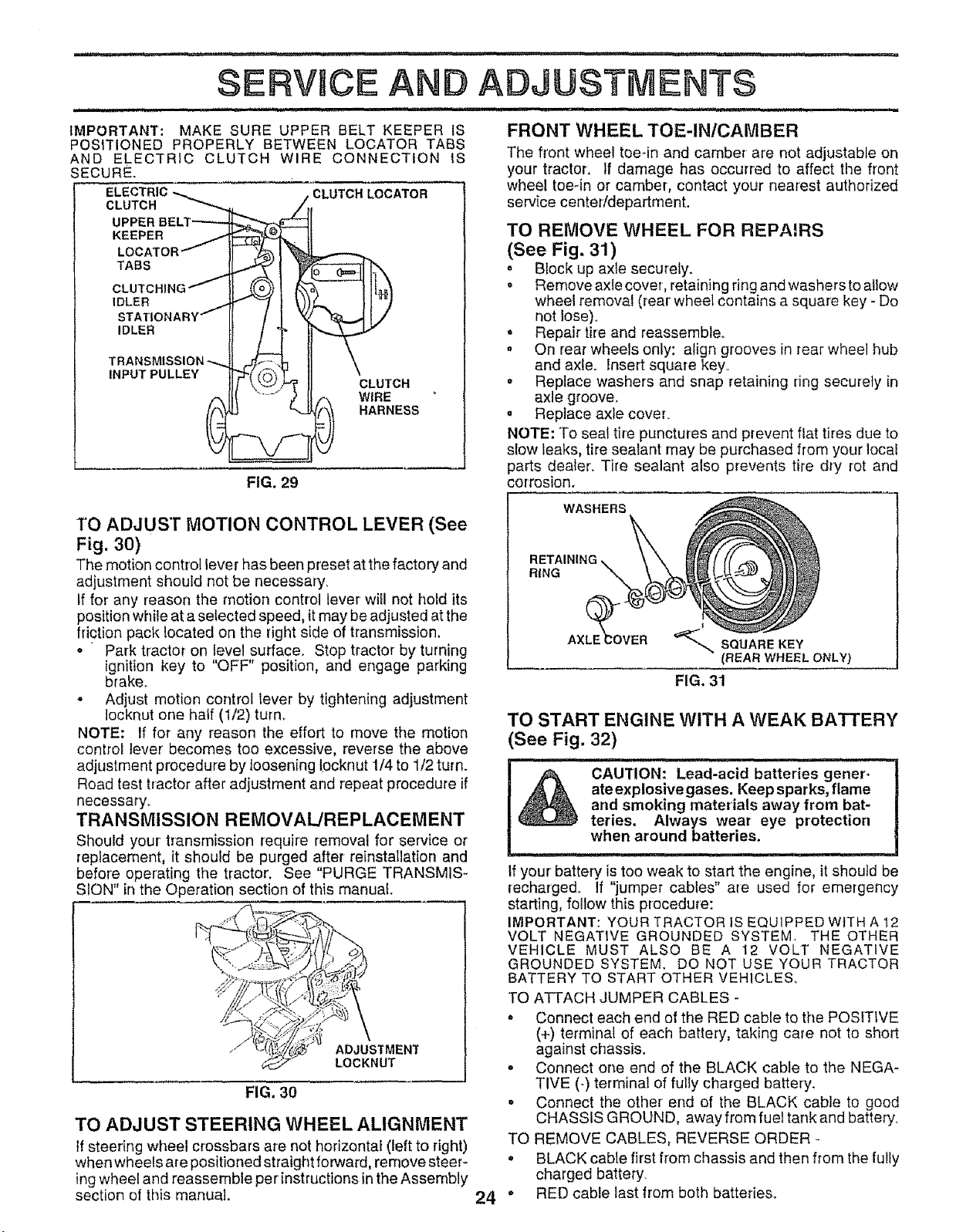
IMPORTANT: MAKE SURE UPPER BELT KEEPER IS
POSITIONED PROPERLY BETWEEN LOCATER TABS
AND ELECTRIC CLUTCH WIRE CONNECTION IS
SECURE.
ELECTRIC _.,,._ , CLUTCH LOCATER
CLUTCH
/,r
:,
UPPER BELT _",_._[
KEEPER / _.|I
LOCATER/ ._ [ '_,.....-..--__
TABS _ I _ b'.
OL°TO.,.GJ
,DLER J "-"-/ t V)_. tl "7
STATIONARY-- / I _ "_--_!/
'°L'" LTP'M"
TRANSMISSION-.......J1-:7.h 11 \
,.PUTPOLLE II ' LO.OH
f', "_2 1!Z". WIRE "
FRONT WHEEL TOE-IN/CAMBER
The front wheel toe-in and camber are not adjustable on
your tractor, If damage has occurred to affect the front
wheel toe-in or camber, contact your nearest authorized
service center/department.
TO REMOVE WHEEL FOR REPAIRS
(See Fig. 31)
° Block up axle securely.
= Remove axle cover, retaining ring and washers to allow
wheel removal (rear wheel contains a square key - Do
not Iose)o
o
Repair tire and reassemble_
, On rear wheels only: align grooves in rear wheel hub
and axle. Insert square key,
• Replace washers and snap retaining ring securely in
axle groove.
o Replace axle coveL
NOTE: To seal tire punctures and prevent flat tires due to
slow leaks, tire sealant may be purchased from your local
parts dearer. Tire sealant also prevents tire dry rot and
corrosion.FIG. 29
TO ADJUST MOTION CONTROL LEVER (See
Fig. 30)
The motion control lever has been preset at the factory and
adjustment shoutd not be necessary.
tf for any reason the motion control lever' will not hold its
position while at a selected speed, it may be adjusted atthe
friction pack located on the right side of transmission.
o Park tractor on level surface. Stop tractor by turning
ignition key to "OFF" position, and engage parking
brake,_
° Adjust motion control lever by tightening adjustment
Iocknut one half (1/2) turn_
NOTE: If for any reason the effort to move the motion
control lever becomes too excessive, reverse the above
adjustment procedure by loosening Iocknut 1/4 to 1/2 turn.
Road test tractor after adjustment and repeat procedure if
necessary..
TRANSMISSION REMOVAL/REPLACEMENT
Should your' transmission require removal for service or
replacement, it should be purged after reinstatlation and
before operating the tractor. See "PURGE TRANSMIS*
SION" in the Operation section of this manual.
FIG. 30
TO ADJUST STEERING WHEEL ALIGNMENT
tf steering wheel crossbars are not horizontal (left to right)
when wheels are positioned straight forward, remove steer_
ing wheel and reassemble perinstructions in the Assembly
section of this manual.
WASHERS
RETAINING
RING
AXLE_OVER
_-,,,SQUAREKEY
(REAR WHEEL ONLY)
FIG, 31
o
o
TO
Q
24"
TO START ENGINE WITH A WEAK BATTERY
(See Fig. 32)
CAUTION: Lead'acid batteries gener. [
A ate explosivegases. Keep sparks, flame
arid smoking materials away from bat- I
teries, Always wear eye protection ]
when ar°und batterles"
your battery is toe weak to start the engine, itshould be
recharged, If "jumper cables" are used for emergency
starting, follow this p_ecedure:
IMPORTANT: YOUR TRACTOR iS EQUIPPED WITH A 12
VOLT NEGATIVE GROUNDED SYSTEM. THE OTHER
VEHICLE MUST ALSO BE A 12 VOLT NEGATIVE
GROUNDED SYSTEM. DO NOT USE YOUR TRACTOR
BATTERY TO START OTHER VEHICLES,
TO ATTACH JUMPER CABLES -
= Connect each end of the RED cable to the POSITIVE
(+) terminal of each battery, taking care not to short
against chassis.
Connect one end of the BLACK cable to the NEGA-
TIVE (-) terminal of fully charged battery.
Connect the other end of the BLACK cable to good
CHASSIS GROUND, away from fuet tank and battery.
REMOVE CABLES, REVERSE ORDER
BLACK cable first from chassis and then from the fully
charged battery.
RED cable last from both batteries.

..... iii
SERVICE AN
i1,111,11,1,1ii
"POSITIVE .... NEGATIVE"
(+) (-)
FIG. 32
TO REPLACE HEADLIGHT BULB
• Raise hood,
. Pull bulb holder out of the hole in the backside of the
grill,
• Replace bulb in holder and push bulb holder securely
back into the hole in the backside of the grill
• Close hood_
INTERLOCKS AND RELAYS
Loose or damaged wiring may cause your tractor to run
poorly, stop running, or prevent it from starting.
• Check wiring, See electrical wiring diagram in the
Repair Parts section of this manual,
TO REPLACE FUSE
Replace with 30 amp automotive-type plug-in fuse, The
fuse holder is located behind the dash,,
TO REMOVE HOOD AND GRILL ASSEMBLY
(See Fig. 33)
o Raise hood.
o Unsnap headlight wire connector.
o Stand infront oftractor. Grasp hood at sides, tilttoward
engine and lift off of tractor.
o To replace, reverse above procedure°
HOOD
ENGINE
FIG. 33
TO ADJUST THROTFLE CONTROL CABLE
(See Figs. 34 & 35)
The throttle control has been preset at the factory and
adjustment should not be necessary, Check adjustment as
described below before loosening cable If adjustment is
necessary, proceed as follows:
,,11,1,,11,1111111,i i ................
ADJUSTMENTS
iiiiii1,,111,,,i,ii, , i i .................iiiiiii, ,i,i, i
• With engine not running, move throttle control lever to
fast (,_) position_
o Check that speed control lever isagainst stop screw. If
it is not, loosen casing clamp screw and pull throttle
cable until lever is against screw. Tighten clamp screw
securely.
CASING STOP SCREW SPEED CONTROL
CLAMP LEVER
SCREW
THROTTLE
CABLE
FIG. 34
STOP
SCREW
SPEED
CONTROL
LEVER
FIG, 35
TO ADJUST CARBURETOR (See Fig. 36)
The carburetor has been present at the factory and adjust-
ment should not be necessary_ However, minor adjustment
may be required to compensate for differences in fuel,
temperature, altitude or load. If the carburetor does need
adjustment, proceed as fol{ows:
In general, turning the adjusting needles in (clockwise)
decreases the supply of fuel to the engine giving a leaner
fuel/air mixture. Turning the adjusting needles out (coun-
terclockwise) increases the supply of fuel to the engine
giving a richer fue!/air mixture
IMPORTANT; DAMAGE TO THE NEEDLES AND THE
SEATS IN CARBURETOR MAY RESULT IF SCREW IS
TURNED 1NTOO TIGHT.
PRELIMINARY SETTING -
. Be sure you have a clean air filter, and the throttle
control cable is adjusted properly (see above)°
• With engine off turn idlefuel adjusting needle in (clock-
wise) closing it finger tight and then turn out (counter-
clockwise) 1-1/4 turns.
o Turn main fuel adjusting needle in (clockwise) closing
finger tight and then turn out (counterclockwise) 1 turn°
25
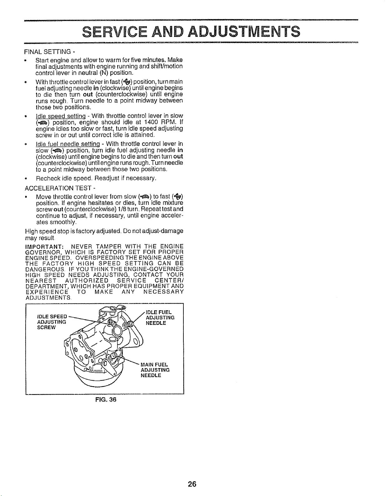
...... i= ,,, =, ,=,-H= .... = i • ,,, ,=,
SERVICE AND ADJUSTMENTS
FINAL SETTING -
= Start engine and allow to warm for five minutes. Make
final adjustments with engine running and shift/motion
control lever' in neutral (N) position°
= With throttle control lever'in fast (,_) position, turn main
fuef adjusting needle in (clockwise) until engine begins
to die then turn out (counterclockwise) until engine
runs rough. Turn needle to a point midway between
those two positions.
= Idle speed settinq - With throttle control lever in stow
(,_) position, engine should idle at 1400 RPM. if
engine idles too stow or fast, turn idrespeed adjusting
screw in or out until correct idle is attained_
o Idle fue! needle settin.q * With throttle control lever in
slow (,_.) position, turn idle fuel adjusting needle in
(clockwise) until engine begins to die and then turn out
(counterctockwise) until engine runsrough°Turn needle
to a point midway between those two positions.
- Recheck idle speed.. Readjust if necessary_
ACCELERATION TEST -
• Move throttle control lever from slow (,_) to fast (,'_)
position._ If engine hesitates or dies, turn idle mixture
screw out (counterclockwise) !/8 turn. Repeat test and
continue to adjust, if necessary, until engine acceler-
ates smoothly.
High speed stop isfactory adjusted. Do not adjust-damage
may result
IMPORTANT: NEVER TAMPER WITH THE ENGINE
GOVERNOR, WHICH iS FACTORY SET FOR PROPER
ENGINE SPEED. OVERSPEEDINGTHEENG[NEABOVE
THE FACTORY HIGH SPEED SETTING CAN BE
DANGEROUS IF YOUTHtNKTHEENGINE-GOVERNED
HIGH SPEED NEEDS ADJUSTING, CONTACT YOUR
NEAREST AUTHORIZED SERVICE CENTER/
DEPARTMENT, WHICH HAS PROPER EQUIPMENT AND
EXPERIENCE TO MAKE ANY NECESSARY
ADJUSTMENTS.
iDLE SPEED
ADJUSTING
SCREW
FUEL
ADJUSTING
NEEDLE
/IAIN FUEL
ADJUSTING
NEEDLE
FIG. 36
26

=n,, ,, r ,=,,,=,,=,,=,==,,= ,, , ,,,i,=1==,== , =,=
STORAGE
1, = = ,, 111 r =,u,i,,u,,, = = m,,r,,,H,,,,,u .... n ' =
Immediately prepare your tractor for storage at the end of ENGnNE
the season or if the tractor will not be used for 30 days or
more, FUEL SYSTEM
CAUTION: Never store the tractor with
gasoline in the tank inside a building
where fumes may reach an open flame
or spark. Allow the engine to cool
before storing in any enclosure,
TRACTOR
Remove mower from tractor for winter storage. When
mower is to be stored for a period of time, clean it thor-
oughly, remove all dirt, grease, leaves, etco Store in a
clean, dry area.
- Clean entire tractor (See"CLEANING" in the Customer
Responsibilities section of this manual),
• Inspect and replace belts, if necessary (See belt re-
placement instructions inthe Service and Adjustments
section of this manual).
• Lubricate as shown in the Customer Responsibilities
section of this manual..
• Be sure that all nuts, bolts and screws are securely
fastened. Inspect moving parts for damage, breakage
and wear. Replace if necessary.
• Touch up all rusted or chipped paint surfaces; sand
lightly before painting.
IMPORTANT: IT IS IMPORTANT TO PREVENT GUM
DEPOSITS FROM FORMING IN ESSENTIAL FUEL
SYSTEM PARTS SUCH AS CARBURETOR, FUEL FILTER,
FUEL HOSE, OR TANK DURING STORAGE. ALSO,
EXPERIENCE INDICATES THAT ALCOHOL BLENDED
FUELS (CALLED GASOHOL OR USING ETHANOL OR
METHANOL) CAN ATTRACT MOISTURE WHICH LEADS
TO SEPARATION AND FORMATION OF ACIDS DURING
STORAGE. ACIDIC GAS CAN DAMAGE THE FUEL
SYSTEM OF AN ENGINE WHILE IN STORAGE
. Drain the fuel tank_
o Start the engine and let it run until the fuel Pinesand
carburetor are empty..
o Never use engine or carburetor cleaner products inthe
fuel tank or permanent damage may occur
o Use fresh fuel next season..
NOTE: Fuel stabilizer is an acceptable alternative in
minimizing the formation of fuel gum deposits during stor-
age,. Add stabilizer to gasoline in fuel tank or storage
container, Always follow the mix ratio found on stabilizer
container. Run engine at least 10 minutes after adding
stabilizer to allow the stabilizer to reach the carburetor. Do
not drain the gas tank and carburetor if using rue} stabilizer.
BATTERY
o Fully charge the battery for storage°
o After a period of time in storage, battery may require
recharging.
• To help prevent corrosion and power leakage during
long periods of storage, battery cables should be
disconnected and battery cleaned thoroughly (see "TO
CLEAN BATTERY AND TERMINALS" in the Cus-
tomer Responsibilities section of this manual).
" After cleaning, leave cables disconnected and place
cables where they cannot come in contact with battery
terminals_
, Be sure battery drain tube is securely attached.
- If battery is removed from tractor for storage, do not
store battery directly on concrete or damp surfaces°.
ENGINE OIL
Drain oil (with engine warm) and replace with clean engine
oil (See "ENGINE" in the Customer Responsibilities
section of this manual).
CYLINDERS
o Remove spark pfug(s).
° Pour one ounce of oil through spark plug hole(s) into
cylinder(s).
• Turn ignition key to"START" position for a few seconds
to distribute oil.
o Replace with new spark plug(s),
OTHER
o Do not store gasoline from one season to another.
, Replace your gasoline can if your can starts to rust.
Rust and/or dirt in your gasoline will cause problems.
° If possible, store your tractor indoors and cover it to
g_ve protection from dust and dirt°
- Cover your tractor with a suitable protective cover that
does not retain moisture. Do not use plastic. Plastic
cannot breathe which allows condensation to form and
will cause your tractor to rust,
IMPORTANT: NEVER COVER TRACTOR WHFLEENGINE
AND EXHAUST AREAS ARE STILL WARM.
27

PROBLEM
Will not start
Hard to start
Engine will not turn over
Engine clicks but will not
start
Loss of power
Excessive vlbratlon
TRO LESHOOTI POINTS
CAUSE CORRECTION
1_ Out of fuel
2. Engine not "CHOKED" properly.
3 Engine flooded.
4 Bad spark plug_
5 Didy a{r filter.
6 Dirty fuel filter,
7_ Water in fuel
8. Looseor damaged wIring
9. Carburetor out of adjustment
10. Engine valves out of adjustmenL
1.. Dldy air filter.
2 Bad spark plug_
3 Weak or dead battery.
4. Dirty fuel filter.
5 Stale or dirty fuel
6 Loose or damaged wiring.
7 Carburetor out of adjustment
8. Engine valves out of adjustment.
1 Clutch/brake pedal not depressed.
2 Attachment clutch is engaged
3_ Weak or dead battery.
4 Blown fuse..
5. Corroded battery terminals.
6_ Loose or damagedwtdng.
7. Faulty ignition switch_
8 Faulty solenoid or starter
9 Faulty operator presence switch(as)
1 Weak or dead battery°
2. Corroded battery terminals.
3. Loose or damaged widng
4. Faultysolenoid or starter..
t Cutting too much grass/too fast.
2 Throttle in "CHOKE" position.
3 Build-up of grass, leaves and trash under mower.
4. Dirty air filter.
5. Low oil leveVdirty oil
6. Faulty spark piug
7. Dirty fuel filter..
8 Stale or dirty fue!.
9 Water in fuel.
10.
11.
12
13_
14o
5o
Spark plug wire Ioose.
Dirty engine air screen/tins.
Dirty/clogged muffler.
Loose or damaged widng..
Carburetor out of adjustment.
Engine valves out of adjustment.
1_ Worn. bent or loose blade.
2. Bent blade mandrel.
3. Loose/damaged part(s).
1_ Filtfuel tank
2 See "TO START ENGINE" in Operation section
3. Wait several minutes before attempting to start
4. Replace spark plug.
5.. Clean/replace air filter.
6 Replace fuel filter
7. Drain fuel tank and carburetor, refill tank with fresh
gasoline and replace fuel filter
8 Check all wiring.
9 See "To Adjust Carburetor" in Service Adjustments
section.
10r ContaCt an authorized servicecenter/department
1. Cieanlreplace air filter
2 Replace spark plug
3 Recharge or replace battery
4 Replace fuel filter
5. Drain fuel tank and refill with fresh gasoline
6_ Check all wiring.
7. See "To Adjust Carburetor" in Service Adjustments
section.
8_ Contact an authorized service center/department
1 Depress clutct_/brake pedal
2. Disengage attachment clutch..
3 Recharge or reptace battery
4 Replace fuse
5 Clean battery terminals.
6. Check all wiring
7. Check/replace ignition switch.
8. Check/replace solenoid or starter.
9 Contact an authorized service centerldepartment
1.. Recharge or replace battery.
2 C_ean battery terminals
3_ Check all wiring
4 Check/replace solenoid or starter
1o Set in "Higher Cut" position/reduce speed
2 Adjust throttle control,
3_ Clean underside of mower housing
4. Clean/replace air filter
5. Check oil leveltchange oil
6. Clean and regap or change spark plug_
7. Replace fuet filter..
8.. Drain fuel tank and refill with fresh gasoline
9r Drain fuel tank and carburetor, refill tank with fresh
gasoline and replace fueEfilter.
10 Connect and tighten spark plug wire.
11 Clean engine air screen]lins
12 Cleantreplsee muffler.
13 Check all wiring.
14 See "To Adjust Carburetor" in Service Adjuslments
section.
15. Contact an authorized service centerldepartmenL
t. Replace blade. Tighten blade bolt
2. Replace blade mandrel.
3. Tightenloose part(s). Replace damaged parts
28

,=m== , =,== =, = ,,4, m,=
TROUBLESHOOTING POmNTS
,,,,,,,,,,,, ,, --.
PROBLEM CORRECTION
Engine continues to run
when operator leaves seat
with attachment clutch
engaged
i = =n =,= Hun =,==,, =4 , = =
Poor cut - uneven
Mower blades will not
rotate
Poor grass discharge
Headlight(s) not working
(if so equipped)
nH = == n== = =
Battery witl not charge
Loss of drive
===
Engine "backfires"
when turning engine
"OFF"
CAUSE
1 Faulty operator-safety presence control system.
I, Worn, bent or loose blade
2, Mower deck nottevel
3 Buildup of grass, leaves, and trash under mower
4., Bent blade mandrel
5 Clogged mower deck vent holes from buildup of
grass, leaves, and trash around mandrels.
1 Obstruction in clutch mechanism
2, Worn/damaged mower drive belt
3 Frozen idler puney
4,, Frozen blade mandret
1r Engine speed too slow
2, Travel speedtoo fast,
3 Wetgrass_
4 Mower deck not level
5 Low/uneven tire air pressure
6 Worn, bent orloose blade
7, Buildup of grass, leaves and trash under mower
8 Mower drive belt worn
9. Blades improperly instalted
10 _mproper blades used
11, Clogged mower deck vent holes from buildup of
grass, leaves, and trash around mandrels.
! Switch is "OFF"
2 Bulb(s) burned out
3 Faulty tight switch
4 Loose or damaged wiring
5 Btown fuse,
1,, Bad battery cell(s)
2, Poorcable connections.
3. Faulty regulator (if so equipped)
4 Faulty alternator
1 Freewheel control in "disengaged" position
2. Motion drive belt worn, damaged, or broken
3 Air trapped in transmission dudng shipment
or servicing
=,u,,,n4,,, =
Check wiring, switches and connections If not
corrected, contact an authorized service center/
department,
1 Replace b_ade Tighten blade bolt
2. Level mower deck
3 Clean underside of mower housing
4 Repface blade mandrel
5 Clean around mandreEs to open vent holes
1, Remove obstruction,
2 Replace mower drive bell
3 Replace idler pulley,,
4 Replace blade mandrel
! Place throttie control in "FAST" position
2 Shift to slower speed
3 Allow grass to dry before mowing
4. Level mower deck
5. Check tires for proper air pressure
6 Replace!sharpen blade Tighten blade bolt,
7_ Clean underside of mower housing,
8. Replace mower drive belt.
9. Reinstall blades sharp edge down
10 Replace with blades listed in this manuat
11 Clean around mandrels to open vent holes
1. Turn switch "ON"
2 Replace bulb(s),
3 Check/replace light switch,
4. Check wiring and connections
5. Replace fuse_,
1 Replace battery,
2 Check/clean all connections
3 Replace regulatOro
4 Replace alternator
1 Place freewheel control in "engaged" position
2. Replace motion drive belt,
3, Purge transmission
Engine throttle control not set at "SLOW"
position for 30 seconds before stopping engine
i,m 4 =,=
1, Move throttle control to "SLOW" position and aIlow
to idle for 30 seconds before stopping engine
29

3O