

®
MODEL NUMBER 917.256430 OWNER'SMANUAL
=Assembly
•Operation
• Customer Responsibilities
•Service and Adjustments
•Repair Parts
CAUTION: Read and follow all safety rules and instructions before operating this equipment.
FOR CONSUMER ASSISTANCE HOT LINE, CALL THIS TOLL FREE NUMBER: 1-800-659-5917
',ll IHIIII!! !1111IIIIIIIIIInl ......
ITo HIHI/ .... ........ _

SAFETY RULES
Safe Operation Practices for Ride-On Mowers
IMPORTANT: THIS CUTTING MACHINE IS CAPABLE OF AMPUTATING HANDS AND FEET AND THROWING OBJECTS.
FAILURE TO OBSERVE THE FOLLOWING SAFETY INSTRUCTIONS COULD RESULT IN SERIOUS INJURY OR DEATH.
I. GENERAL OPERATION
Read, understand, and follow alt instructions in the manual
and on the machine before starting.
Only allow responsible adults, who are familiar with the
instructions, to operate the machine.
•Clear the area of objects such as rocks, toys, wire, etc.,
which could be picked up and thrown by the blade.
Be sura the area isclearofother people before mowing. Stop
machine ifanyone enters the area.
Never carry passengers.
•Do not mow inreverse unless absolutely necessary. Always
look down and behind before and while backing.
• Be aware of the mower discharge _rectlen anO do not point
it at anyone. Do not operate the mower without either the
entire grass catcher or the guard in place,
Slow down before turning,
Never leave a running machine unattended. Always turn off
blades, set parking brake, stop engine, and remove keys
before dismounting.
• Turn off blades when net mowing.
• Stop engine before removing grass catcher or unclogging
chute.
Mow only in daylight or good artificial light.
" Do not operate the machine white under the influence of
alcohol or drugs.
Watch for traffic when operating near or crossing roadways.
Use extra care when loading or unloading the machine into
a trailer or truck.
IL SLOPE OPERATION
Slopes are a major factor related to loss-of-control and
tipover accidents, which can result in severe injury or death.
All slopes require extra caution. If you cannot back up the
slope or if you feel uneasy on it, do not mow it.
DO: Mow up and down slopes, not across.
•Remove obstacles such as rocks, tree limbs, etc.
Watch for holes, ruts, or bumps. Uneven terrain could
overturn the machine. Tall grass can hide obstacles,
• Use slow speed. Choose a low gear so that you willnot have
to stop or shift while on the slope.
• Follow the manufacturer's recommendations for wheel
weights or counterweights to improve stability.
• Use extra care with grass catchers or other attachments.
These can change the stability of the machine.
Keep all movement on the slopes slowand gradual Do not
make sudden changes in speed or direction,
Avoid starting or stopping on a slope. If tires lose traction,
disengage the blades and proceed slowly straight down the
slope.
DO NOT:
•Donotturoonslopesuntessnecessary, andthen, turos_owly
and gradually downhill, if possible.
•Do notmow near drop-offs, ditches, or embankments. The
mower could suddenly turn over if a wheel is over the edge
of a cliff or ditch, or if an edge caves in,
•Do not mow on wet grass. Reduced traction could cause
sliding.
•Do not try to stabilize the machine by puttingyour foot on the
ground.
•Do not use grass catcher on steep slopes.
2
IlL CHILDREN
Tragic accidents can occur if the operator is not alert to the
presence of children, Children are often attracted to the
machine and the mowing activity. Never assume that
children will remain where you last saw them.
Keep children out of the mowing area and under the watchfuI
care of another responsible adult.
Be alert and turn machine off if children enter the area.
•Before and when backing, look behind and down for small
children.
Never carry children, They may fall off and be seriously
injured or interfere with safe machine operation,
Never allow children to operate the machine.
Use extra care when approaching blind corners, shrubs,
trees, or other objects that may obscure vision.
&
IV, SERVICE
Useextracareinhandlinggasolineandotherfuels, They are
flammable and vapors are explosive.
Use only an approved container.
Never remove gas cap or add fuel with the engine
running. Allow engine to cool before refueling. Do not
smoke.
Never refuel the machine indoors.
Never store the machine or fuel container inside where
there is an open flame, such as a water heater.
• Never run amachine inside aclosed area.
Keep nuts and bolts, especially blade attachment bolts, tight
and keep equipment in good condition.
• Never tamper with safety devices. Check their proper
operation regularly.
•Keep machine free of grass, leaves, or other debris build-up.
Clean oil or fuel spillage. Allow machine to cool before
stodng.
Stop and inspect the equipment if you stdke an object.
Repair, if necessary, before restading,
•Never make adjustments or repairs with the engine running,
Grass catcher components are subject towear, damage, and
deterioration, which could expose moving parts or allow
objects to be thrown. Frequently check components and
replace with manufacturer's recommended parts, when nec-
essary.
Mower blades are sharp and can cut. Wrap the blade(s) or
wear gloves, and use extra caution when servicing them,
Check brake operation frequently. Adjust and service as
required. ii
Look for this symbol to point out ira-
pedant safety precautions. It means
CAUTION!t! BECOMEALERT!!! YOUR
SAFETY IS INVOLVED.
CAUTION: Always disconnect spark plug
wire and place wire where It cannot contact
spark plug tn order to prevent accidental
starting when setting up, transporting,
adjusting or making repairs,
•ILWARNING ,A
The engine exhaust from this product con_.
tains cnemicals known to the State of Calit'or
nJa to cause cancer, birth defects, or other
reproductive harm.

CONGRATULATIONS on your purchase of a Sears
Tractor. It has been designed, engineered and manufac-
tured to give you the best possible dependability and
performance.
Should you experience any problem you cannot easily
remedy, please contact your nearest Sears Authorized
Service Center/Department, We have competent, well-
trained technicians and the proper tools to service or repair
this tractor.
Please read and retain this manual. The instructions wilt
enable you to assemble and maintain your tractor properly.
Always observe the "SAFETY RULES".
MODEL
NUMBER 917.256430
SERIAL
!NUMBER
DATEOFPURCHASE
TH E MODEL AND SERIAL NUMBERS WILL BE FOUND
ON A PLATE UNDER THE SEAT.
YOUSHOULDRECORDBOTHSERIALNUMBERAND
DATE OF PURCHASE AND KEEP IN A SAFE PLACE
FOR FUTURE REFERENCE.
PRODUCT SPECIFICATIONS
HORSEPOWER: 15.5
GASOLINE CAPACITY 5 QUARTS
AND TYPE: UNLEADED REGULAR
OIL TYPE (API-SF/SG): SAE 30 (above 32°F)
SAE 5W-30 (below 32"F)
OIL CAPACITY: 30 PINTS
SPARK PLUG: CHAMPION RJ19LM
GAP: .030") STD361458
VALVE CLEARANCE: INTAKE: .005" - ,007"
EXHAUST: .009" -.0t t"
GROUND SPEED (MPH}: FORWARD: 5.5
REVERSE: 2.4
TIRE PRESSURE: FRONT: 14PS!
REAR: 10 PSI
CHARGlNG SYSTEM: 3 AMPS BATTERY
5 AMPS HEADLIGHTS
BATTERY: AMPiHR: 25
MIN, CCA: 190
CASE SIZE: U1R
BLADE BOLT TORQUE: 30_35 FT. LBS.
MAINTENANCE AGREEMENT
A Sears Maintenance Agreement is available on this prod-
uct. Contact your nearest Sears store for details.
CUSTOMER RESPONSIBILITIES
Read and observe the safety rules.
• Follow a regular schedule in maintaining, caring for and
using your tractor.
Follow the instructions under "Customer Responsibili-
ties" and "Storage" sections of this owner's manual.
WARNING: This tractor is equipped with an internal
combustion engine and should not be used on or near any
unimproved forest*covered, brush-covered or grass-cov-
ered land unless the engine's exhaust system is equipped
with a spark arrester meeting applicable local or state taws
(if any). If a spark arrester is used, it should be maintained
in effective working order by the operator.
In the state of California the above is required by law
(Section 4442 of the California Public Resources Code).
Other states may have similar laws. Federal laws apply on
federal lands. A spark arrester for the muffler is available
through your nearest Sears Authorized Service Center/
Department (See REPAIR PARTS section of this manual
LIMITED TWO YEAR WARRANTY ON CRAFTSMAN RIDING EQUIPMENT
For two (2) years from the date of purchase if this Craftsman Riding Equipment is maintained, Inbricated and tuned up according
to the instructions in the owner's manual, Sears will repair or replace, free of charge, any palts found to be defective in material
or workmanship.
This Warranty does not cover:
Expendable items which become worn during normal use, such as blades, spark plugs, air cleaners, belts, etc.
Tire replacement or repair caused by punctures from outside objects, such as nails, thorns, stumps, or glass.
Repairs necessary because of operator abuse, negligence, improper storage or accident or the failure to maintain the
equipment according to the instructions contained in the owner's manual.
Riding equipment used for commercial or rental purposes.
LIMITED 90 DAY WARRANTY ON BATTERY
For ninety (90) days from date of purchase, if any battery included with this riding equipment proves defective in material or
workmanship and our testing determines the battery will not hold a charge, Sears will replace the battery at no charge
IN-HOME WARRANTY SERVICE ON YOUR CRAFTSMAN RIDING EQUIPMENT IS AVAILABLE AT NO-CHARGE FOR 30
DAYS FROM THE DATE OF PURCHASE. PLEASE CONTACT YOUR NEAREST SERVICE CENTER AFTER 30 DAYS
FROM THE DATE OF PURCHASE, WARRANTY SERVICE IS AVAILABLE BY TAKING YOUR CRAFTSMAN RIDING EQUIP-
MENT TO YOUR NEAREST SEARS SERVICE CENTER. (IN-HOME WARRANTY SERVICE WILL STILL BE AVAILABLE
AFTER 30 DAYS FROM THE DATE OF PURCHASE BUT A STANDARD TRIP CHARGE WILL APPLY.) THIS WARRANTY
APPLIES ONLY WHILE THIS PRODUCT IS IN THE UNITED STATES.
This Warranty gives you specific legal rights, and you may also have other rights which may vary from state to state.
SEARS, ROEBUCK AND CO., D/817 WA, HOFFMAN ESTATES, IL 60179
3
TABLE OF CONTENTS
SAFETY RULES ............................................................ 2
PRODUCT SPECIFICATIONS ...................................... 3
CUSTOMER RESPONSIBILITIES ..................... 3, 17-21
WARRANTY .................................................................. 3
TABLE OF CONTENTS ................................................. 4
INDEX ............................................................................ 4
TRACTOR ACCESSORIES .......................................... 5
ASSEMBLY ............................................................. 7-10
OPERATION .......................................................... 11-16
MAINTENANCE SCHEDULE ..................................... 17
SERVICE AND ADJUSTMENTS ........................... 22-27
STORAGE ................................................................... 28
TROUBLESHOOTING ......................................... ;. 29-30
REPAIR PARTS - TRACTOR ................................ 32-47
REPAIR PARTS - ENGINE .................................... 50-55
PARTS ORDERING/SERVICE .................. BACK PAGE
INDEX A
Accessories ............................................ 5
Adjustments:
Brake ........................................... 24
Carburetor ................................... 27
Mower:
Front-To-Back ........................ 23
Side-To-Side .......................... 23
Throttle Control Cable ................. 27
• o
Air Ftlter, Engine ................................. __o
Air Screen, Engine ............................. 20
Assembly ......................................... 7-10
B
Battery,:
Charging ....................................... 8
Cleaning ...................................... t 9
Connectin< .................................... 7
Starting with Weak Battery ......... 26
Storage ....................................... 28
Terminals .................................... 19
Belts:
Motion Drive
Removal/Replacement .......... 24
Mower Blade Driv3
Removal/Replacement .......... 23
Blade:
Sharpening ................................. 18
Replacement ............................... 18
Brake Adjustment ............................... 24
O
Carburetor Adjustment ....................... 27
Controls. Tractor .................... ............ I2
Customer Responsibilities ............ 17-21
Engine:
Air Filter ................................... 20
Air Screen, Engine .................. 20
Batten/ ..................................... ! 8
Cooling Fins, Engine ............... 21
Engine Oit ............................... 19
Fuel Filter ................................ 21
Spark Plugs ............................ 21
Tractor:
Blades .................................... 18
Lubrication Chart .................... 17
Maintenance Schedule ........... 17
Tire Care ........................ 8,18,27
Cutting Height, Mower ...................... 13
E
Electrical:
Interlocks and ReIays ................. 26
Schematic ................................... 31
Wiring Diagram ........................... 32
Engine:
Air Filter ....................................... 20
Air Screen ................................... 20
Cooling Fins, Engine ................... 20
Oit Change .................................. 19
Oil Level ................................. 15,19
Oil Type ....................................... 18
Preparation ................................. 15
Repair Parts ........................... 50-55
Starting ........................................ 15
Storage ....................................... 28
F
Filters:
Air ................................................ 20
Fuel ............................................. 21
Fuel:Type ............................................ 15
Storage ....................................... 28
Fuse ................................................... 26
G
Gauge Wheels ..................................... 9
H
Hood Removal/installation ................. 26
L
Leveling Mower Deck ......................... 23
Lubrication Chart ................................ 16
M
Maintenance Schedule ...................... ! 7
Mower:
Adjustment, FronFto-Baek .......... 23
Adjustment, Side-to-Side ............ 23
Blade Sharpening ....................... t8
Blade Replacement .................... ! 8
Cutting Height ............................. 13
installation................................... 22
Operation .................................... 14
Removal ...................................... 22
Mowing Tips ...................................... 16
Muffler ............................................... 21
Spark Arrestor ......................... 3,42
Mulcher Plate ................................. 10
4
O
OiI: Cold Weather Conditions ....... 15,19
Engine ......................................... 19
Storage ....................................... 28
Operation ...................................... t 1-16
Operating Mower ................................ 14
Options:
Accessories ................................... 5
Spark Arrester .......................... 3,42
P
Parking Brake .............................. 12-13
Parts Bag ............................................. 6
Parts. Replacement:Repair ........... 32-47
Product Specifications ........................... 3
R
Repair Parts .................................. 32-47
s
Safety Rules ......................................... 2
Seat ...................................................... 8
Service and Adjustments ............. 2t-26
Brake ........................................... 23
Carburetor ................................... 26
Fuse ............................................ 25
Hood Removal/Installation .......... 25
Motion Drive Belt
Removal/RepIacement ........... 23
Mower Blade Drive Belt
RemovaltReplacement ........... 23
Mower Adjustment:
Front-to-Back ......................... 22
Side-to-Side ........................... 22
Mower Installation ....................... 21
Mower Removal .......................... 21
Tire Care ............................. 8,17,24
Slope Guide Sheet ............................. 57
Spark P_ugs........................................ 20
Specifications ....................................... 3
Starling the Engine ........................... 14
Steering Wheel ................................ 7,24
Stopping the Tractor ........................... 12
Storage .............................................. 27
T
Throttle ControI Cable Adjustment .,... 26
Tires ........................................... 8,17,24
]rouble Shooting Chart .................. 28-29
Transaxte Repair Parts ................. 48-49
w
Warranty ............................................... 3
Wiring Diagram .................................. 32
Wiring Schematic ............................... 31
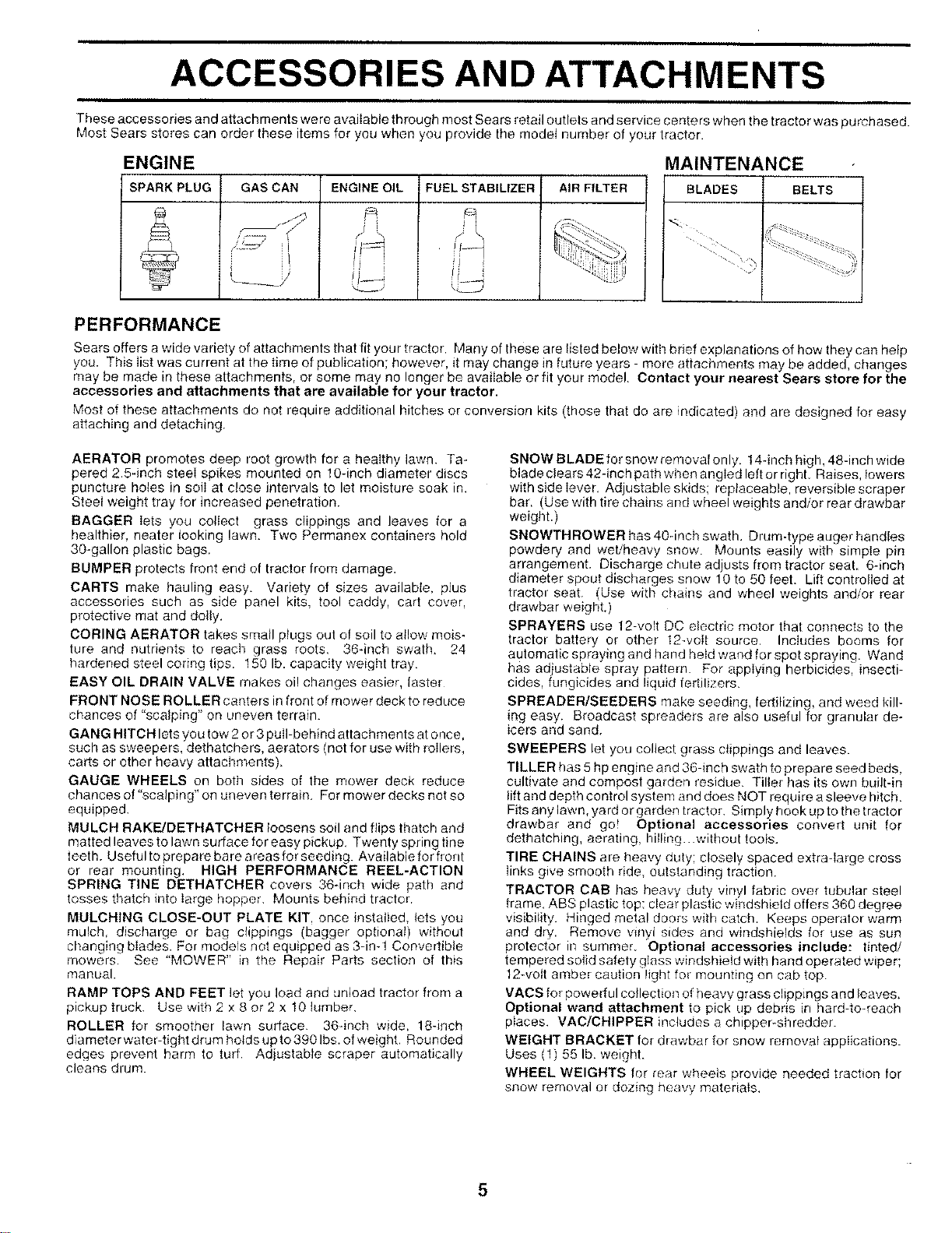
ACCESSORIES AND ATTACHMENTS
These accessories and attachments were available through most Sears retail outlets and service centers when the tractor was purchased.
Most Sears stores can order these items for you when you provide the model number of your tractor.
ENGINE MAINTENANCE
SPARK PLUG GAS CAN ENGINE OIL FUEL STABILIZER AIR FILTER BLADES BELTS
il _f ,! i
PERFORMANCE
Sears offers awide variety of attachments that fit your tractor. Many of these are listed below with brief explanations of how they can help
you. This Iist was current at the time of publication; however, it may change in future years - more attachments may be added, changes
may be made in these attachments, or some may no longer be available or fit your model. Contact your nearest Sears store for the
accessories and attachments that are available for your tractor.
Most of these attachments do not require additional hitches or conversion kits (those that do are indicated) and are des gned for easy
attaching and detaching.
AERATOR promotes deep root growth for a healthy lawn. Ta-
pered 2.5qnch steei spikes mounted on 10-inch diameter discs
puncture holes in soiI at close intervals to let moisture soak in.
Steel weight tray for increased penetration.
BAGGER lets you collect grass clippings and leaves for a
healthier heater looking lawn. Two Permanex containers hold
30-gallon plastic bags
BUMPER protects front end of tractor from damage.
CARTS make hauling easy. Variety of sizes available, plus
accessories such as side panel kits, tool caddy, cart cover,
protective mat and dolly.
CORING AERATOR takes small plugs out of soil to atlow mois-
ture and nutrients to reacI7 grass roots, 36*inch swath. 24
hardened steel coring tips. 150 lb. capacity weight tray.
EASY OIL DRAIN VALVE makes oi! changes easier, faster
FRONT NOSE ROLLER canters in front of mower deck to reduce
chances of "scalping" on uneven terrain.
GANG HITCH lets you tow 2 or 3 puII-behind attachments at once,
such as sweepers, dethatchers, aerators (not for use with rollers,
carts or other heavy attachments).
GAUGE WHEELS on both sides of the mower deck reduce
chances of "scalping" on uneven terrain. For mower decks not so
equipped.
MULCH RAKE/DETHATCHER loosens soil and flips thatch and
matted leaves to lawn surface for easy pickup, Twenty spring tine
teeth. Usefulto prepare hare areas for seeding. Available for front
or rear mounting, HIGH PERFORMANCE REEL-ACTION
SPRING TINE DETHATCHER covers 36dnch wide path and
tosses thatch into large hopper Mounts behind tractor.
MULCHING CLOSE-OUT PLATE KIT, once installed, lets you
mulch, discharge or bag clippings (bagger optional) without
changing blades. For models not equipped as 3-in-1 Convertible
mowers See "MOWER" in the Repair Parts section of this
manual.
RAMP TOPS AND FEET let you load and unload tractor from a
pickup truck_ Use with 2 x 8 or 2 x I0 lumber,
ROLLER for smoother lawn surface 36-inch wide, 18-inch
diameter water-tight drum holds up to 3901bs. of weight, Rounded
edges prevent harm to turf Adjustable scraper automatically
cleans drum
SNOW BLADE for snow removal only. 14qnch high, 48-inch wide
blade clears 42-inch path when angled left or right. Raises, lowers
with side lever, Adjustable skids; replaceable, reversible scraper
bar. (Use with tire chains and wheel weights and/or rear drawbar
weight.)
SNOWTHROWER has 404nch swath. Drumdype auger handles
powdery and wet/heavy snow. Mounts easily with simple pin
arrangement. Discharge chute adjusts from tractor seat 6-inch
diameter spout discharges snow 10 to 50 feet. Lift controlled at
tractor seat. (Use with chains and wheel weights and/or rear
drawbar weight.)
SPRAYERS use 12-volt DC electric motor that connects to the
tractor battery or other 12-volt source, Includes booms for
automatic spraying and hand held wand for spot spraying. Wand
has adjustahle spray pattern. For applying herbicides, insecti-
cides, fungicides and liquid fertilizers.
SPREADER/SEEDERS make seeding, fertilizing, and weed kill-
_ngeasy. Broadcast spreaders are also useful for granular de-
icers and sand.
SWEEPERS let you collect grass clippings and leaves.
TILLER has 5 hp engine and 36-inch swath to prepare seed beds,
cultivate and compost garden residue. Tiller has its own built-in
liftand depth control system and does NOT require asleeve hitch.
Fits any lawn, yard or garden tracton Simply hook up to the tractor
drawbar and go! Optional accessories convert unit for
dethatching, aerating, hilling..without tools.
TIRE CHAINS are heavy duty; closely spaced extra-large cross
links give smooth ride outstanding traction
TRACTOR CAB has heavy duty vinyl fabric over tubular steel
frame, ABS plastic top: clear plastic windshield offers 360 degree
visibitity. Hinged metal doors with catch. Keeps operator warm
and dry Remove wnyl sides and windshields for use as sun
protector in summer Optional accessories include: tinted/
tempered solid safety glass windshield with hand operated wiper;
12-volt amber caution light fo_ mounting on cab top
VACS for powedul collection of heavy grass clippings and leaves.
Optional wand attachment to pick Lip debris in hard-to-reach
places. VAC/CRIPPER includes a chipper-shredder
WEIGHT BRACKET for drawbar for snow removal applications.
Uses (1) 55 lb. weight.
WHEEL WEIGHTS for rear wheels provide needed traction for
snow removal or dozing heavy materials,
5

CONTENTS OF HARDWARE PACK
Parts Bag contents shown full size
(1) Large
Fiat Washer
Locknut 3/8-24
(1) Hex Bolt 5/16-18 x 1ol/4
(1) Locknut 5/16-18
(1) Hex Bolt
1/2-13 x 1
i , ./i,H
\\ <2),ookWashers,,lO_
"', (2) Screws #10 x 5/8
O (2) We,d Nuts #10L_
2) Washers 3/16 x 3/4 x 16 Gauge _L_
)/32 x 5/8 x 16 Gauge t2) Lock Washers 1/4
Parts packed separately in carton
Seat Mulcher
Plate
il .....,
Steering
Wheel --_
L.......I
I Video
I Cassette
m
........ .... i
Manual Pa_s Bag
g
Boot
i
Parts bag contents not shown full size
_"f-" (2) Washers 3/8
X _,/ x 7/8 x 14 Gauge
(2) Shoulder
Bolts (2) Center-
Q lock Nuts
" (2) Gauge
Wheels
Steering Wheel
Adapter (2) Keys
(2) Latch Hook
Assembiys
Slope Sheet
Steering
Extension
Shaft
= I
/--'--N
z
\
Steering
Wheel
Insert
6
ASSEMBLY
Your new tractor has been assembled at the factory with exception of those parts left unassembled for shipping purposes.
To ensure safe and proper operation of your tractor all parts and hardware you assemble must be tightened securely. Use
the correct tools as necessary to insure proper tightness.
TOOLS REQUIRED FOR ASSEMBLY
A socket wrench set will make assembly easier. Standard
wrench sizes are listed.
(1) 5/16" wrench (1) 3/4" Socket w/drive rachet
(2) 7/16" wrenches Phillips Screwdriver
(1) 1/2" wrench Tire pressure gauge
(1) 9/16" wrench Utility knife
When right or left hand is mentioned in this manual, it
means when you are in the operating position (seated
behind the steering wheel).
TO REMOVE TRACTOR FROM CARTON
UNPACK CARTON
• Remove all accessible loose parts and parts cartons
from carton (See page 6).
• Cut, from top to bottom, along lines on all four corners
of carton, and lay panels flat.
• Check for any additional loose parts or cartons and
remove.
BEFORE ROLLING TRACTOR OFF SKID
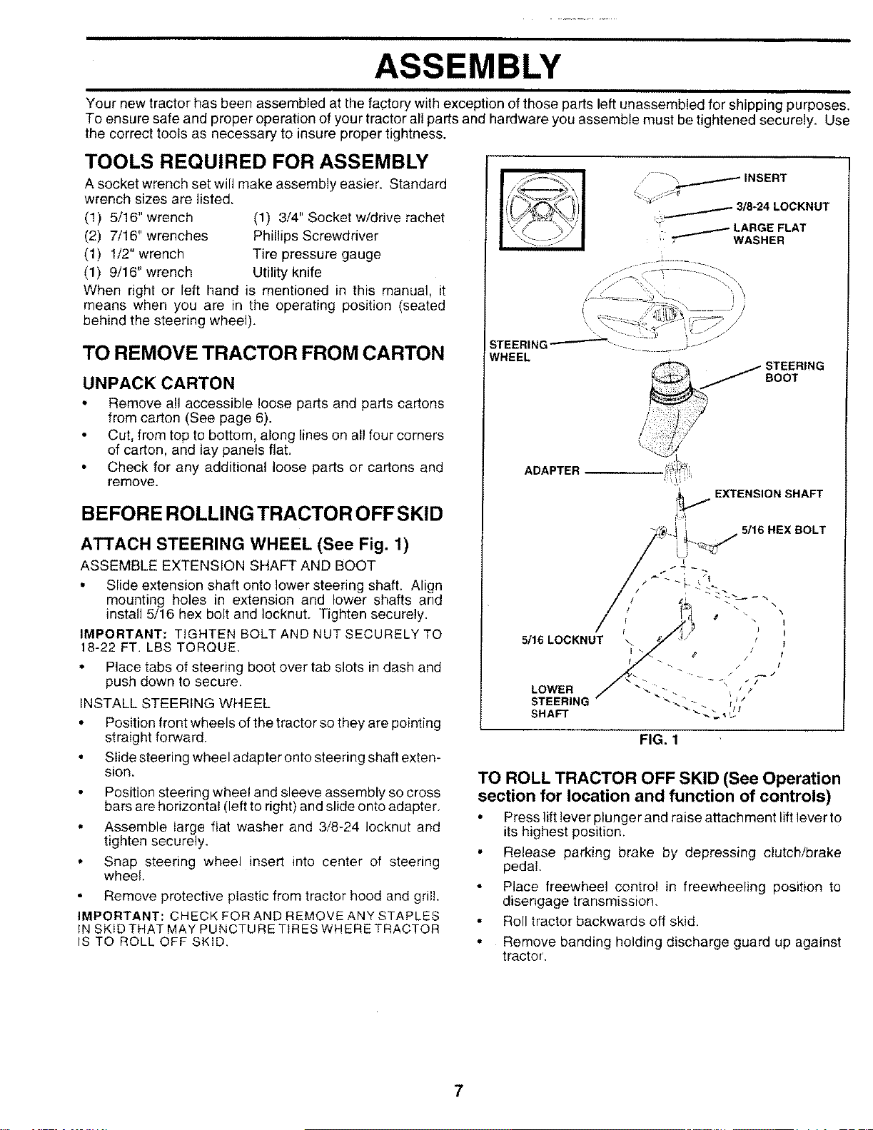
ATTACH STEERING WHEEL (See Fig. 1)
ASSEMBLE EXTENSION SHAFT AND BOOT
• Slide extension shaft onto lower steering shaft. Align
mounting holes in extension and lower shafts and
install 5/16 hex bolt and Iocknut. Tighten securely.
IMPORTANT: TIGHTEN BQLT AND NUT SECURELY TO
18-22 FT. LBS TORQUE.
Place tabs of steering boot over tab slots in dash and
push down to secure.
INSTALL STEERING WHEEL
Position front wheels of the tractor so they are pointing
straight forward.
Slide steering wheel adapter onto steering shaft exten-
sion.
Position steering wheel and sleeve assembly so cross
bars are horizontal (left to right) and slide onto adapter
Assemble large fiat washer and 3/8-24 Iocknut and
tighten securely.
Snap steering wheel insert into center of steering
wheel.
Remove protective plastic from tractor hood and grill.
IMPORTANT: CHECK FOR AND REMOVE ANY STAPLES
IN SKIDTHAT MAY PUNCTURE TIRES WHERE TRACTOR
IS TO ROLL OFF SKID.
I
,'- "'_, INSERT
/
./ 3/8-24 LOCKNUT
/LARGE FLAT
7"- WASHER
WHEEL STEERING
BOOT
ADAPTER
FIG. 1
TO ROLL TRACTOR OFF SKID (See Operation
section for location and function of controls)
Press lift lever plunger and raise attachment lift lever to
its highest position.
Release parking brake by depressing clutch/brake
pedal.
Place freewheel control in freewheeling position to
disengage transmission.
• Roll tractor backwards off skid.
•Remove banding holding discharge guard up against
tractor.
ASSEMBLY
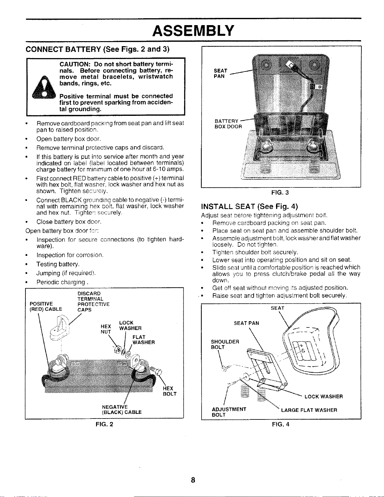
CONNECT BATTERY (See Figs. 2 and 3)
CAUTION: Do not short battery termi-
nals. Before connecting battery, re-
move metal bracelets, wristwatch
bands, rings, etc.
Positive terminal must be connected
first to prevent sparking from acciden-
tal grounding.
• Remove cardboard packing from seat pan and iift seat
pan to raised position.
• Open battery box door.
• Remove terminal protective caps and discard.
• If this battery is put into service after month and year
indicated on label (label located between terminals)
charge battery for minimum of one hour at 6-I0 amps.
First connect RED battery cable to positive (+) terminal
with hex bolt, fiat washer, lock washer and hex nut as
shown. Tighten se_ureJy.
Connect BLACK grounding cable to negative (-) termi-
nal with remaining hex bolt. flat washer, lock washer
and hex nut. Tighter_ securely.
Close battery box door.
Open battery box door fcr:
Inspection for secure connections (to tighten hard-
ware).
• Inspection for corrosion.
• Testing battery.
• Jumping (if required}.
• Periodic charging.
POSITIVE
(RED) CABLE
DISCARD
TERMfNAL
PROTECTIVE
CAPS
LOCK
HEX WASHER
NUT FLAT
WASHER
HEX
BOLT
NEGATIVE
(BLACK) CABLE
SEAT
PAN
BOX DOOR
FIG. 3
INSTALL SEAT (See Fig. 4)
Adjust sea__eTore tightening adjustmen_ boit.
• Remove cardboard packing on seat pan.
• Place seat on seat pan and assemble shoulder boit.
• AssemDle adjustment bott, Iock washer and flat washer
loosely. Do not tighten.
• Tighten shoulder bolt securely.
• Lower seat into operating position and sit on seat.
• Slide seat until a comfortable position is reached which
allows you to press clutch/brake pedal all the way
down,
Get off seat without moving its adjusted position.
Raise seat and tighten adjustment bolt securely,
SEAT
SEAT PAN
SHOULDER
BOLT
ADJUSTMENT
BOLT
LOCK WASHER
.AT WASHER
FIG. 2 FIG. 4
8
i i i i i i • i i ii ii ii i i
ASSEMBLY
CHECK TIRE PRESSURE
The tires on your tractor were overinflated at the factory for
shipping purposes. Correct tire pressure is important for
best cutting performance.
• Reduce tire pressure to PS! shown in "PRODUCT
SPECIFICATIONS" on page 3 of this manual.
CHECK DECK LEVELNESS
For best cutting results, mower housing should be properly
leveled, See "TO LEVEL MOWER HOUSING" in the
Service and Adjustments section of this manual.
CHECK FOR PROPER POSITION OF ALL
BELTS
See the figures that are shown for replacing motion and
mower blade drive belts in the Service and Adjustments
section of this manual. Verify that the belts are routed
correctly.
CHECK BRAKE SYSTEM
Afteryou learn how to operate your tractor, check to see that
the brake is properly adjusted. See "TO ADJUST BRAKE"
in the Service and Adjustments Section of this manual.
i i
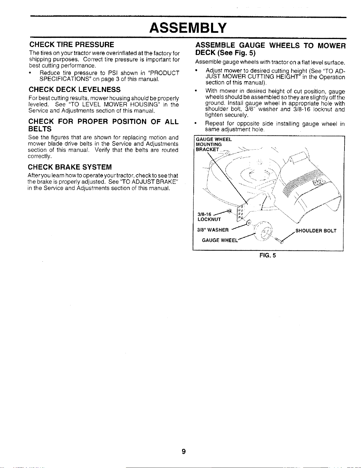
ASSEMBLE GAUGE WHEELS TO MOWER
DECK (See Fig. 5)
Assemble gauge wheels with tractor on a flat level surface.
• Adjust mower to desired cutting hei,_ht (See "TO AD-
JUST MOWER CUTTING HEIGHT in the Operation
section of this manual).
With mower in desired height of cut position, gauge
wheels should be assembled so they are slightly off the
ground. Install gauge wheel in appropriate hole with
shoulder bolt, 3/8" washer and 3/8-16 Iocknut and
tighten securely.
• Repeat for opposite side installing gauge wheel in
same adjustment hole.
GAUGE WHEEL
MOUNTING
BRACKET
3!8-16_
LOCKNUT
3/8" WASHER
GAUGE WHEEL
\\\
SHOULDER BOLT
FIG. 5
9
ASSEMBLY
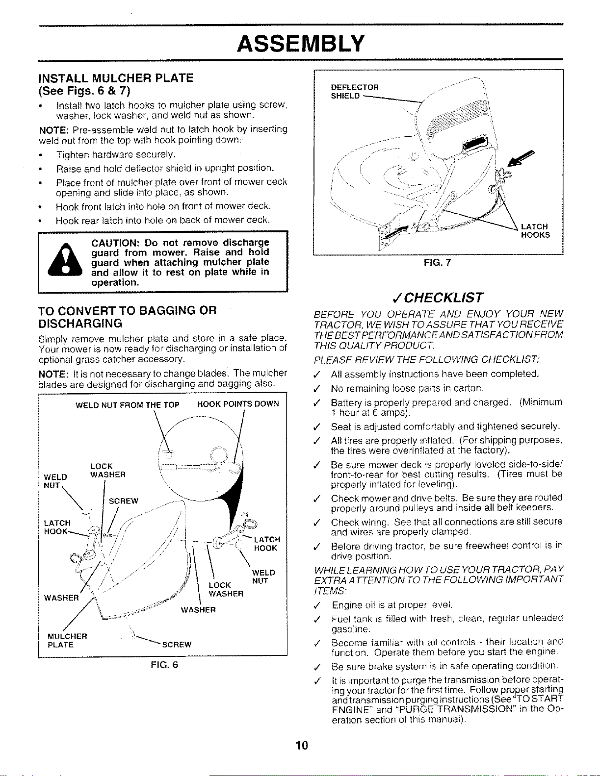
INSTALL MULCHER PLATE
(See Figs. 6 & 7)
Install two latch hooks to muIcher plate using screw,
washer, lock washer, and weld nut as shown.
NOTE: Pre-assembIe weld nut to latch hook by inserting
weld nut from the top with hook pointing down:.
Tighten hardware securely,
Raise and hold deflector shield in upright position.
• Place front of muIcher plate over front of mower deck
opening and slide into place, as shown.
Hook front latch into hole on front of mower deck.
• Hook rear latch into hole on back of mower deck.
&CAUTION: Do not remove discharge
guard from mower. Raise and hold
guard when attaching mulcher plate
and allow it to rest on plate while in
operation.
TO CONVERT TO BAGGING OR
DISCHARGING
Simply remove mulcher plate and store in a safe place.
Your mower is now ready for discharging or installation of
optional grass catcher accessory,
NOTE: it is not necessary to change blades The mulcher
blades are designed for discharging and bagging also,
WELD NUT FROM THE TOP HOOK POINTS DOWN
LOCK
WELD WASHER _,
NUT \
Z'
LATCH /," /
// /i I
s?' ILATCH
HOOK
WELD
NUT
MULCHER _'*_SCREW
PLATE
FIG. 6
DEFLECTOR
LATCH
HOOKS
FIG. 7
,/CHECKLIST
BEFORE YOU OPERATE AND ENJOY YOUR NEW
TRACTOR, WE WISH TO ASSURE THAT YOU RECEIVE
THE BEST PERFORMANCE AND SA TISFAC TION FROM
THIS QUALITY PRODUCT.
PLEASE REWEW THE FOLLOWING CHECKLIST."
,/ All assembly instructions have been completed.
,/ No remaining loose parts in carton.
¢" Battery is properly prepared and charged. (Minimum
1 hour at 6 amps).
¢" Seat is adjusted comfortably and tightened securely.
,/ All tires are properly inflated. (For shipping purposes,
the tires were overinfiated at the factory).
JBe sure mower deck is properly leveled side-to-side/
front-to rear for best cutting results. (Tires must be
properly inflated for leveling).
JCheck mower and drive belts. Be sure they are routed
properly around pulleys and inside all belt keepers.
,/ Check wiring. See that all connections are still secure
and wires are properly clamped.
JBefore driving tractor, be sure freewheel control is in
drive position.
WHILE LEARNING HOW TO USE YOUR TRACTOR, PAY
EXTRA ATTENTION TO THE FOLLOWING IMPORTANT
ITEMS:
¢" Engine oil is at proper level.
lFuel tank is filled with fresh, c;ean, regular unleaded
gasoline.
,/ Become familiar with all controls - their location and
function. Operate them before you start the engine.
,/ Be sure brake system is in safe operating condition.
¢" It isimportant to purge the transmission before operat-
ing your tractor for the first time. FolIow proper starting
and transmission purging instructions (See 'TO START
ENGINE" and "PURGE TRANSMISSION" in the Op-
eration section of this manual).
10

OPERATION
These symbols may appear on your product or in literature supplied with the product, Learn and understand their meaning.
BATTERY CAUTION OR
WARNING
ENGINE ON ENGINE OFF
REVERSE FORWARD
OIL PRESSURE CLUTCH
FAST SLOW
LIGHTS ON LIGHTS OFF
FUEL I'--,Ir-,-@
CHOKE MOWER HEIGHT DIFFERENTIAL
LOCK 0 @
PARKING BRAKE UNLOCKED
LOCKED
I
MOWER LIFT
REVERSE NEUTRAL
ATTACHMENT
CLUTCH ENGAGED
HL
HIGH LOW
i
ATTACHMENT
CLUTCH DISENGAGED
PARKING BRAKE
IGNITION
HYDROSTATIC FREE WHEEL
DANGER, KEEP HANDS AND FEET AWAY (Hydro Models only)
11
OPERATION
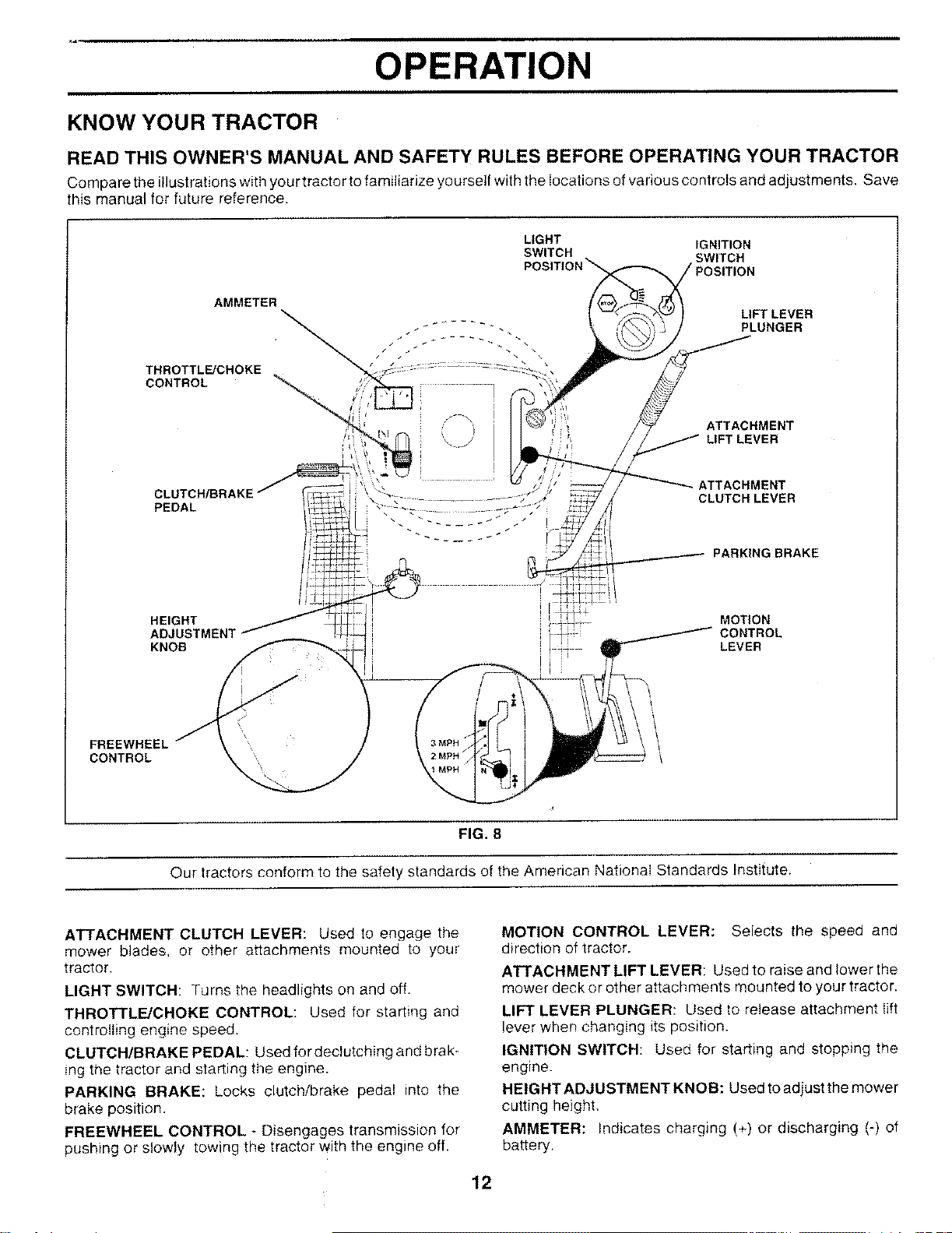
KNOW YOUR TRACTOR
READ THIS OWNER'S MANUAL AND SAFETY RULES BEFORE OPERATING YOUR TRACTOR
Compare the illustrations with your tractor to familiarize yourself with the locations of various controls and adjustments. Save
this manual for future reference.
LIGHT IGNITION
SWITCH
POSITION\ SWITCH
AMMETER
THROTTLE/CHOKE
CONTROL
LIFT LEVER
PLUNGER
PEDAL
;J ;IATTACHMENT
/, iLIFT LEVER
ATTACHMENT
CLUTCH LEVER
PARKING BRAKE
FREEWHEEL
CONTROL
HEIGHT
KNOB
MOTION
CONTROL
LEVER
FIG. 8
Our tractors conform to the safety standards of the American National Standards Institute.
ATTACHMENT CLUTCH LEVER: Used to engage the
mower blades, or other attachments mounted to your
tractor.
LIGHT SWITCH: Turns the headlights on and off.
THROTTLE/CHOKE CONTROL: Used for starting and
controlling engine speed.
CLUTCH/BRAKE PEDAL: Used for declutching and brak-
ing the tractor and starting the engine.
PARKING BRAKE: Locks clutch/brake pedal into the
brake position.
FREEWHEEL CONTROL *Disengages transmission for
pushing or slowly towing the tractor with the engine off.
MOTION CONTROL LEVER: Selects the speed and
direction of tractor,
ATTACHMENT LIFT LEVER: Used to raise and lower the
mower deck or other attachments mounted to your tractor.
LIFT LEVER PLUNGER: Used to release attachment lift
lever when changing its position.
IGNITION SWITCH: Used for starting and stopping the
engine.
HEIGHT ADJUSTMENT KNOB: Used to adjust the mower
cutting height,
AMMETER: Indicates charging (+) or discharging (-) of
battery.
12
OPERATION
I
The operation of any tractor can result in foreign objects thrown into the eyes, which can |
result in severe eye damage. Always wear safety glasses or eye shields while operating your I
tractor or performing any adjustments or repairs. We recommend a wide vision safety mask
over the spectacles or standard safety glasses.
HOW TO USE YOUR TRACTOR
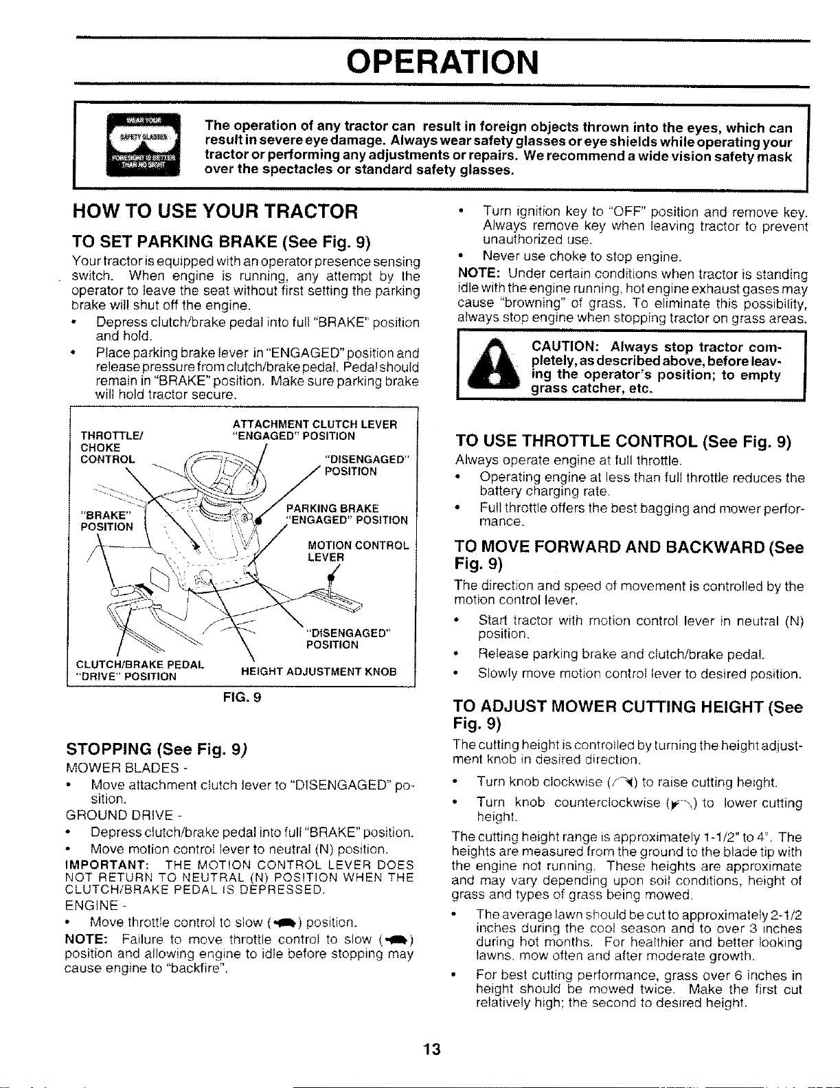
TO SET PARKING BRAKE (See Fig. 9)
Your tractor is equipped with an operator presence sensing
switch. When engine is running, any attempt by the
operator to leave the seat without first setting the parking
brake wil! shut off the engine.
• Depress clutch/brake pedal into full "BRAKE" position
and hold.
• Place parking brake lever in "ENGAGED" position and
release pressure from clutch/brake pedal, Pedal should
remain in "BRAKE" position. Make sure parking brake
will hold tractor secure.
• Turn ignition key to "OFF" position and remove key.
Always remove key when leaving tractor to prevent
unauthorized use.
• Never use choke to stop engine.
NOTE: Under certain conditions when tractor is standing
idle with the engine running, hot engine exhaust gases may
cause "browning" of grass. To eliminate this possibility,
always stop engine when stopping tractor on grass areas.
ICAUTION: Always stop tractor com-
pletely, as described above, before leav-
ing the operator's position; to empty
grass catcher, etc.
THROTTLE/
CHOKE
CONTROL
ATTACHMENT CLUTCH LEVER
"ENGAGED" POSITION
"DISENGAGED"
='BRAKE"
POSITION
PARKING BRAKE
'ENGAGED'POSITION
MOTION CONTROL
LEVER
"DISENGAGED"
POSITION
CLUTCH/BRAKEPEDAL
'=DRIVE'POSITION HEIGHT ADJUSTMENT KNOB
FIG. 9
STOPPING (See Fig. 9)
MOWER BLADES -
Move attachment clutch lever to "DISENGAGED" po-
sition.
GROUND DRIVE -
Depress clutch/brake pedal into full "BRAKE" position.
Move motion control lever to neutral (N) position.
IMPORTANT: THE MOTION CONTROL LEVER DOES
NOT RETURN TO NEUTRAL (1t) POSITION WHEN THE
CLUTCH/BRAKE PEDAL IS DEPRESSED.
ENGINE -
Move throttle control tO slow (,_b) position.
NOTE: Failure to move throttle control to slow (,,_t_)
position and allowing engine to idle before stopping may
cause engine to "backfire".
TO USE THROTTLE CONTROL (See Fig. 9)
Always operate engine at full throttle.
Operating engine at less than full throttle reduces the
battery charging rate.
• Full throttle offers the best bagging and mower perfor-
mance.
TO MOVE FORWARD AND BACKWARD (See
Fig, 9)
The direction and speed of movement is controlled by the
motion control lever.
• Start tractor with motion control lever in neutral (N)
position.
• Release parking brake and clutchibrake pedal.
• Slowly move motion control lever to desired position.
TO ADJUST MOWER CUTTING HEIGHT (See
Fig. 9)
The cutting height is controlled by turning the height adjust-
ment knob in desired direction.
Turn knob clockwise (,_-_1)to raise cutting height.
• Turn knob counterclockwise (1#-_,)to lower cutting
height.
The cutting height range is approximately 1-1/2" to 4'1.The
heights are measured from the ground to the blade tip with
the engine not running. These heights are approximate
and may vary depending upon soil conditions, height of
grass and types of grass being mowed.
The average lawn should be cutto approximately 2-1/2
inches during the coot season and to over 3 inches
during hot months. For healthier and better looking
lawns, mow often and after moderate growth.
• For best cutting performance, grass over 6 inches in
height should be mowed twice. Make the first cut
relatively high; the second to desired height.
13
OPERATION
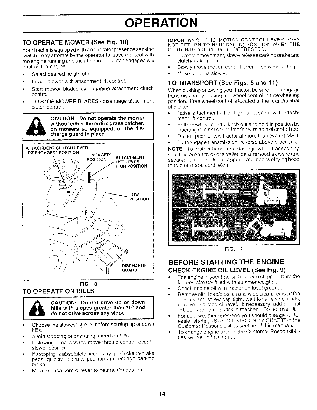
TO OPERATE MOWER (See Fig. 10)
Your tractor is equipped with an operator presence sensing
switch. Any attempt by the operator to leave the seat with
the engine running and the attachment clutch engaged wilt
shut off the engine.
• Select desired height of cut.
• Lower mower with attachment lift control.
• Start mower blades by engaging attachment clutch
control.
TO STOP MOWER BLADES - disengage attachment
clutch control.
ICAUTION: Do not operate the mower
without either the entire grass catcher,
on mowers so equipped, or the dis-
charge guard in place.
ATTACHMENT CLUTCH LEVER
"DISENGAGED" POSITION "ENGAGED"
POSITION ATTACHMENT
VER
HIGH POSITION
//LOW
I POSITION
I I
DISCHARGE
GUARD
FIG. 10
TO OPERATE ON HILLS I
CAUTION: Do not drive up or down I
hills with slopes greater than 15°and I
do not drive across any slope.
Choose the slowest speed before starting up or down
hills.
Avoid stopping or changing speed on hills.
If slowing is necessary, move throttle control lever to
slower position.
If stopping is absolutely necessary, push clutch/brake
pedal quickly to brake position and engage parking
brake.
Move motion control lever to neutral (N) position.
IMPORTANT: THE MOTION CONTROL LEVER DOES
NOT RETURN TO NEUTRAL (N) POSITION WHEN THE
CLUTCH/BRAKE PEDAL IS DEPRESSED.
• TOrestart movement, slowly release parking brake and
clutch!brake pedal.
Slowly move motion control lever to slowest setting.
° Make aHturns slowly.
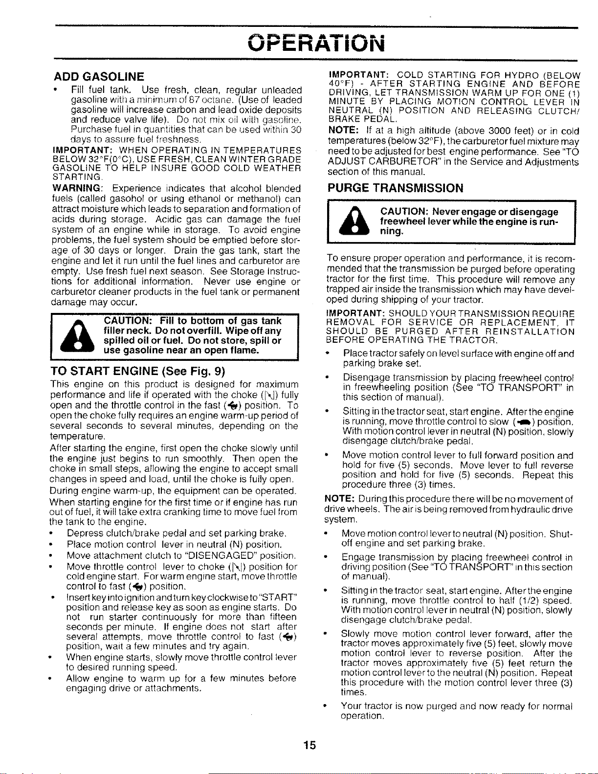
TO TRANSPORT (See Figs. 8and 11)
When pusMng or towing your tractor, be sure to disengage
transmission by placing freewheel control in freewheeling
position. Free wheel contro! is located at the rear drawbar
of tractor.
Raise attachment lift to highest position with attach-
ment lift control.
• Pull freewheel control knob out and hold in position by
inserting retainer spring into fo_Tard hole of control rod.
• Do not push or tow tractor at more than two (2) MPH.
• To reengage transmission, reverse above procedure.
NOTE: To protect hood from damage when transporting
your tractor on atrucker atrailer, be sure hood isctosed and
secured to tractor. Use an appropriate means oftying hood
to tractor (rope, cord. etc.).
FIG. 11
BEFORE STARTING THE ENGINE
CHECK ENGINE OIL LEVEL (See Fig. 9)
The engine in your tractor has been shipped, from the
factory, already filled with summer weight oil.
Check engine oil with tractor on levet ground.
Remove oil fill cap/dipstick and wipe clean, reinsert the
dipstick and screw cap tight, wait for a few seconds,
remove and read oil level. If necessary, add oil until
"FULL" mark on dipstick is reached. Do not oveKill.
• For cold weather operation you should change oil for
easier starting (See "OIL VISCOSITY CHART" in the
Customer ResponsibiNties section of this manual).
To change engine oil. see the Customer Responsibili-
ties section in this manual
14
OPERATION
ADD GASOLINE
Fill fuel tank. Use fresh, clean, regular unleaded
gasoline with a minimum of 87 octane. (Use of leaded
gasoline will increase carbon and lead oxide deposits
and reduce valve life). Do not mix oil with gasoline.
Purchase fuel in quantities that can be used within 30
days to assure fuel freshness.
IMPORTANT: WHEN OPERATING tN TEMPERATURES
BELOW 32"F(0 C), USE FRESH, CLEAN WINTER GRADE
GASOLINE TO HELP INSURE GOOD COLD WEATHER
STARTING.
WARNING: Experience indicates that alcohol blended
fuels (called gasohol or using ethanol or methanol) can
attract moisture which leads to separation and formation of
acids during storage. Acidic gas can damage the fuel
system of an engine while in storage. To avoid engine
problems, the fuel system should be emptied before stor-
age of 30 days or longer. Drain the gas tank, start the
engine and let it run until the fuel lines and carburetor are
empty. Use fresh fuel next season. See Storage Instruc-
tions for additional information. Never use engine or
carburetor cleaner products in the fuel tank or permanent
damage may occur.
_b AUTION: Fill to bottom of gas tank I
filler neck. Do not overfill. Wipe off any I
spilled oil or fuel. Do not store, spill or
use gasoline near an open flame.
TO START ENGINE (See Fig. 9)
This engine on this product is designed for maximum
performance and life if operated with the choke (N) fully
open and the throttle control in the fast (,_) position. To
open the choke fully requires an engine warm-up period of
several seconds to several minutes, depending on the
temperature.
After starting the engine, first open the choke slowly until
the engine just begins to run smoothly. Then open the
choke in small steps, allowing the engine to accept small
changes in speed and load, until the choke is fully open.
During engine warm-up, the equipment can be operated.
When starting engine for the first time or if engine has run
out of fuel, it will take extra cranking time to move fuel from
the tank to the engine.
Depress clutch!brake pedal and set parking brake.
Place motion control lever in neutral (N) position.
Move attachment clutch to "DISENGAGED" position.
Move throttle control lever to choke (N) position for
cold engine start. For warm engine start, move throtlle
control to fast (,_) position.
Insert key into ignition and turn key clockwise Io"START'
position and release key as soon as engine starts. Do
not run starter continuously for more than fifteen
seconds per minute. If engine does not start after
several attempts, move throttle control to fast (,1_)
position, wait a few minutes and try again.
When engine starts, slowly move throttle control lever
to desired running speed.
• Allow engine to warm up for a few minutes before
engaging drive or attachments.
IMPORTANT: COLD STARTING FOR HYDRO (BELOW
40°F) - AFTER STARTING ENGINE AND BEFORE
DRIVING, LET TRANSMISSION WARM UP FOR ONE (1)
MINUTE BY PLACING MOTION CONTROL LEVER iN
NEUTRAL (N) POSITION AND RELEASING CLUTCH/
BRAKE PEDAL,
NOTE: If at a high altitude (above 3000 feet) or in cold
temperatures (below 32°F), the carburetor fue! mixture may
need to be adjusted for best engine performance. See "TO
ADJUST CARBURETOR" in the Service and Adjustments
section of this manual.
PURGE TRANSMISSION
CAUTION: Never engage or disengage I
freewheel lever while the engine is run-
ning.
To ensure proper operation and performance, it is recom-
mended that the transmission be purged before operating
tractor for the first time. This procedure will remove any
trapped air inside the transmission which may have devel-
oped during shipping of your tractor.
IMPORTANT: SHOULD YOUR TRANSMISSION REQUIRE
REMOVAL FOR SERVICE OR REPLACEMENT, IT
SHOULD BE PURGED AFTER REINSTALLATION
BEFORE OPERATING THE TRACTOR.
• Place tractor safety on level surface with engine off and
parking brake set.
Disengage transmission by placing freewheel control
in freewheeling position (See "TO TRANSPORT" in
this section of manual).
• Sitting in thetractor seat, start engine. After the engine
is running, move throttle control to slow (,_b) position.
With motion control lever in neutral (N) position, slowly
disengage clutch/brake pedal.
• Move motion control lever to full forward position and
hold for five (5) seconds. Move lever to full reverse
position and hold for five (5) seconds. Repeat this
procedure three (3) times.
NOTE: During this procedure there will be no movement of
drive wheels. The air is being removed from hydraulic drive
system.
• Move motion control lever to neutral (N) position. Shut-
off engine and set parking brake.
Engage transmission by placing freewheel control in
driving position (See "TO TRANSPORT" in this section
of manual).
Sitting in the tractor seat, start engine. After the engine
is running, move throttle control to half (1/2) speed.
With motion control lever in neutral (N) position, slowly
disengage clutch/brake pedal.
Slowly move motion control lever forward, after the
tractor moves approximately five (5) feet, slowly move
motion control lever to reverse position. After the
tractor moves approximately five (5) feet return the
motion control lever to the neutral (N) position. Repeat
this procedure with the motion control lever three (3)
times.
Your tractor is now purged and now ready for normal
operation.
15
OPERATION
MOWING TIPS MULCHING MOWING TIPS
• Tire chains cannot be used when the mower housing
is attached to tractor.
•Mower should be properly leveled for best mow!,n.g
performance. See "TO LEVEL MOWER HOUSING in
the Service and Adjustments section of this manual.
• The left hand side of mower should be used for trim-
ming.
Drive so that clippings are discharged onto the area
that has been cut. Have the cut area to the right of the
machine. This will result in a more even distribution of
clippings and more uniform cutting.
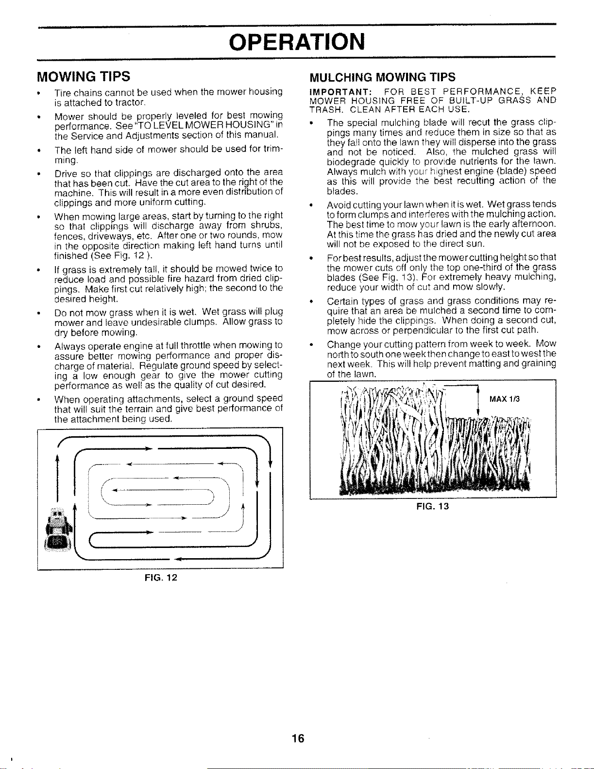
• When mowing large areas, start by turning to the right
so that clippings will discharge away from shrubs,
fences, driveways, etc. After one or two rounds, mow
in the opposite direction making left hand turns until
finished (See Fig. 12 ).
• If grass is extremely tail, it should be mowed twice to
reduce load and possible fire hazard from dried clip-
pings. Make first cut relatively high; the second to the
desired height.
• Do not mow grass when it is wet. Wet grass will plug
mower and leave undesirable clumps. Allow grass to
dry before mowing.
Always operate engine at full throttle when mowing to
assure better mowing performance and proper dis-
charge of material. Regulate ground speed by select-
ing a low enough gear to give the mower cutting
performance as well as the quality of cut desired.
When operating attachments, select a ground speed
that will suit the terrain and give best performance of
the attachment being used.
FIG. 12
IMPORTANT: FOR BEST PERFORMANCE, KEEP
MOWER HOUSING FREE OF BUILT-UP GRASS AND
TRASH, CLEAN AFTER EACH USE,
The special mulching blade will recur the grass clip-
pings many times and reduce them in size so that as
they fall onto the lawn they wiii disperse into the grass
and not be noticed. Also, the mulched grass will
biodegrade quickly to provide nutrients for the lawn.
Always mulch with your highest engine (blade) speed
as this will provide the best recutting action of the
blades.
• Avoid cutting your lawn when it iswet. Wet grass tends
to form clumps and interferes with the mulching action.
The best time to mow your lawn is the early afternoon.
At this time the grass has dried and the newly cut area
will not be exposed to the direct sun.
• For best results, adjust the mower cutting height so that
the mower cuts off only the top one-third of the grass
blades (See Fig. !3). For extremely heavy mulching,
reduce your width of cut and mow slowly.
• Certain types of grass and grass conditions may re-
quire that an area be mulched a second time to com-
pletely hide the clippings. When doing a second cut,
mow across or perpendicular to the first cut path.
Change your cutting pattern from week to week. Mow
north to south one week then change to east to west the
next week_ This will help prevent matting and graining
of the lawn.
MAXI_
FIG. 13
16
CUSTOMER RESPONSIBILITIES
1-Change more often when operating under a heavy load or in high ambient temperatures.
2 - Service more often when operabr)g in dirty or dusty conditions¸
g - I_equipped wiftl oir fi_tP.F,change oi_ every 50 hours¸
4 - Replace blades more, o fte,_ when mowing in sanely soiL
5-If equipped with adjustable system
6 • Not required if equipped with maintenance4ree battery
7 - Tighten front a×_e pivot bolt to 35 {t -Ibs. ma×irnum
DO r_ot overtighten
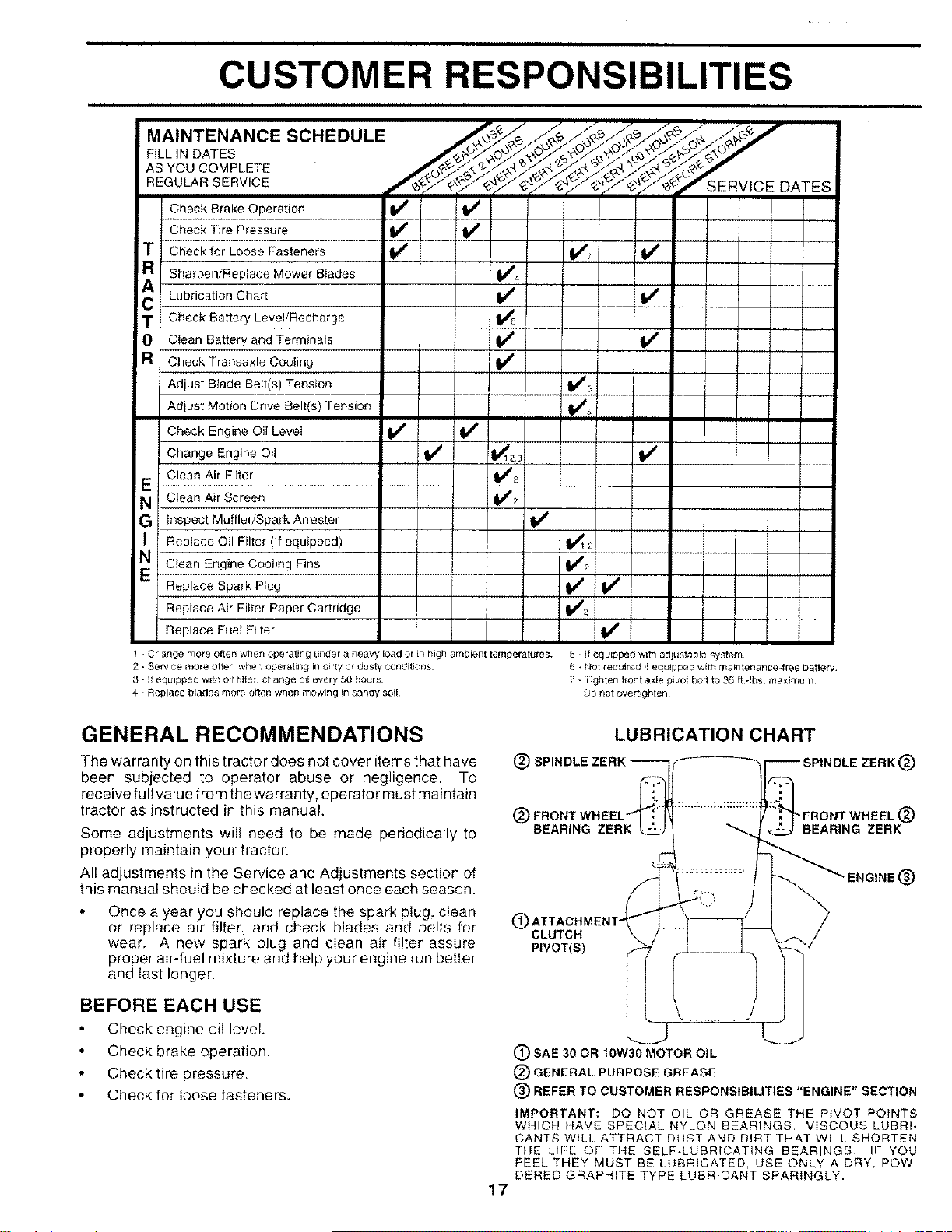
GENERAL RECOMMENDATIONS
The warranty on this tractor does not cover items that have
been subjected to operator abuse or negligence. To
receive ful! value from the warranty, operator must maintain
tractor as instructed in this manual.
Some adjustments will need to be made periodically to
properly maintain your tractor,
All adjustments in the Service and Adjustments section of
this manual should be checked at least once each season.
LUBRICATION CHART
(_) SPINDLE _)
(_) "FRONT WHEEL (_)
REARING ZERK BEARING ZERK
Once a year you should replace the spark plug, clean f_
or replace air filter and check blades and belts for LDCLUTCH
wear, A new spark plug and clean air filter assure PIVOT(S)
proper air-fuel mixture and help your engine run better
and last longer.
BEFORE EACH USE
Check engine oil level
Check brake operation.
Check tire pressure.
Check for loose fasteners•
ENGINE (_
(_) SAE 30 OR 10W30 MOTOR OIL
(_) GENERAL PURPOSE GREASE
(_) REFER TO CUSTOMER RESPONSIBILITIES "ENGINE" SECTION
IMPORTANT: DO NOT OIL OR GREASE THE PIVOT POINTS
WHICH HAVE SPECIAL NYLON BEARINGS, VISCOUS LUBRI-
CANTS WILL ATTRACT DUST AND DIRT THAT WILL SHORTEN
THE LIFE OF THE SELF-LUBRICATING BEARINGS IF YOU
FEEL THEY MUST BE LUBRICATED, USE ONLY A DRY, POW-
DERED GRAPHITE TYPE LUBRICANT SPARINGLY.
17
i
CUSTOMER RESPONSIBILITIES
TRACTOR
Always observe safety rules when performing any mainte-
nance.
BRAKE OPERATION
If tractor requires more than six (6) feet stopping distance
at high speed in highest gear, then brake must be adjusted.
(See "TO ADJUST BRAKE" in the Service and Adjust-
ments section of this manual).
TIRES
Maintain proper air pressure in all tires (See "PROD-
UCT SPECIFICATIONS" on page 3 of this manual),
Keep tires free of gasoline, oit, or insect control chemi-
cals which can harm rubber.
• Avoid stumps, stones, deep ruts, sharp objects and
other hazards that may cause tire damage.
BLADE CARE
For best results mower blades must be kept sharp, Re-
place bent or damaged blades.
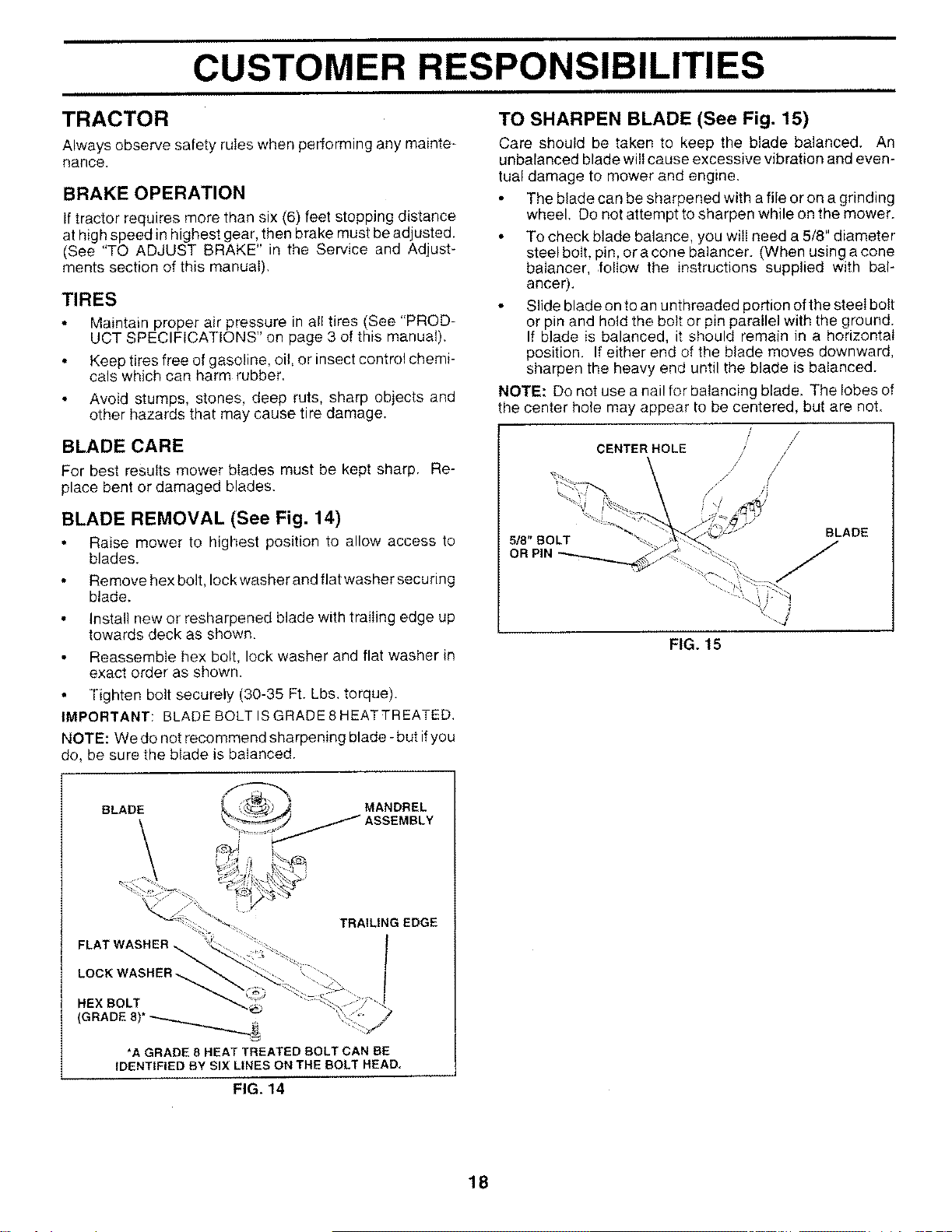
BLADE REMOVAL (See Fig. 14)
Raise mower to highest position to allow access to
blades.
Remove hex bolt, lock washer and flat washer securing
blade.
• Install new or resharpened blade with trailing edge up
towards deck as shown.
Reassemble hex bolt, lock washer and flat washer in
exact order as shown.
Tighten bolt securely (30-35 Ft. Lbs. torque).
IMPORTANT: BLADE BOLT ISGRADE8HEATTREATED.
NOTE: We do not recommend sharpening blade- but ifyou
do, be sure the blade is balanced.
BLADE MANDREL
\_) ASSEMBLY
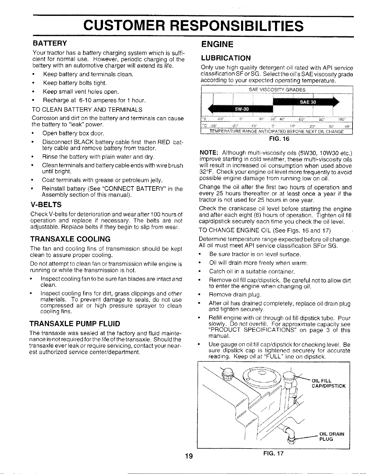
TO SHARPEN BLADE (See Fig. 15)
Care should be taken to keep the blade balanced. An
unbalanced blade will cause excessive vibration and even-
tual damage to mower and engine.
• The blade can be sharpened with a file or on a grinding
wheel. Do not attempt to sharpen while on the mower.
• To check blade balance, you will need a 5/8" diameter
steel bolt, pin, or a cone balancer. (When using a cone
baiancer, foliow the instructions supplied with bal-
ancer).
• Slide blade on to an unthreaded portion of the steel bolt
or pin and hold the bolt or pin parallel with the ground.
If blade is balanced, it should remain in a horizontal
position. If either end of the blade moves downward,
sharpen the heavy end until the blade is balanced.
NOTE: Do not use a nai! for balancing blade, The lobes of
the center hote may appear to be centered, but are not,
/
/
CENTER HOLE / /
/! //
5/8" BOLT
OR PIN
BLADE
FIG. 15
TRAILING EDGE
FLAT WASHER
LOCK WASHER
HEX BOLT
(GRADE 8)* _ _,
*A GRADE 8 HEAT TREATED BOLT CAN BE
IDENTIFIED BY SIX LINES ON THE BOLT READ,
FIG. 14
18
ii i
CUSTOMER RESPONSIBILITIES
ENGINE
BATTERY
Your tractor has a battery charging system which is suffi-
cient for normal use. However, periodic charging of the
battery with an automotive charger will extend its life,
Keep battery and terminals clean.
Keep battery bolts tight.
• Keep small vent holes open.
Recharge at 6-10 amperes for 1 hour.
TO CLEAN BATTERY AND TERMINALS
Corrosion and dirt on the battery and terminals can cause
the battery to "leak" power.
Open battery box door.
• Disconnect BLACK battery cable first then RED bat-
tery cable and remove battery from tractor•
• Rinse the battery with plain water and dry.
• Clean terminals and battery cable ends with wire brush
until bright.
• Coat terminals with grease or petroleum jelly.
• Reinstall battery (See "CONNECT BATTERY" in the
Assembly section of this manual).
V-BELTS
Check V-belts for deterioration and wear after I00 hours of
operation and replace if necessary. The belts are not
adjustable. Reptace belts if they begin to slip from wear•
TRANSAXLE COOLING
The fan and cooling fins of transmission should be kept
clean to assure proper cooling.
Do not attempt to clean fan or transmission while engine is
running or while the transmission is hot,
Inspect cooling fan to be sure fan blades are intact and
clean•
Inspect cooling fins for dirt, grass clippings and other
materials. To prevent damage to seals, do not use
compressed air or high pressure sprayer to clean
cooling fins.
TRANSAXLE PUMP FLUID
The transaxle was sealed at the factory and fluid mainte-
nance is.not required for the life of the transaxle, Should the
transaxle ever Ieak or require servicing, contact your near-
est authorized service center/department,
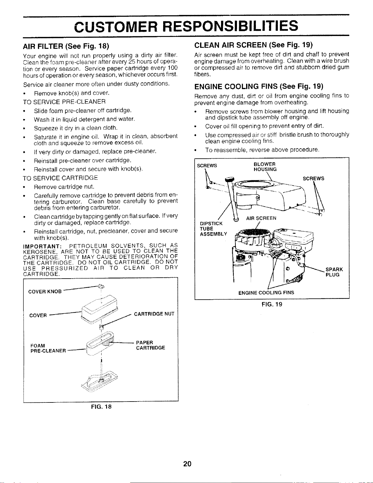
LUBRICATION
Only use high quality detergent oil rated with API service
classification SF or SG. Select the oil's SAE viscosity grade
according to your expected operating temperature.
SAEVISCOSITYGRADES
i
20' 0' 30 _ 32" 400 60 _' 80 n 100 °
-30 _ -20 _ 10 0° tOI 20 _ 30 _ 40 _'
TEMPERATURE RANGE ANT/CIRATED BEFORE NEXT OIL CHANGE
FIG. 16
NOTE: Although multi-viscosity oils (5W30, 10W30 etc.)
improve starting in cold weather, these multi-viscosity oils
wiii result in increased oil consumption when used above
32°F. Check your engine oil level more frequently to avoid
possible engine damage from running low on oil.
Change the oil after the first two hours of operation and
every 25 hours thereafter or at least once a year if the
tractor is not used for 25 hours in one year,
Check the crankcase oil level before starting the engine
and after each eight (8) hours of operation. Tighten oil fill
cap/dipstick securely each time you check the oil level.
TO CHANGE ENGINE OIL (See Figs. 16 and 17)
Determine temperature range expected before oil change.
All eli must meet API service classification SFor SG.
Be sure tractor is on level surface.
Oi! wil! drain more freely when warm.
Catch oil in a suitable container•
Remove oil fill cap/dipstick. Be careful not to allow dirt
to enter the engine when changing oil.
Remove drain plug.
After oil has drained completely, replace oil drain plug
and tighten secureJy.
Refill engine with oil through oil fill dipstick tube. Pour
slowly• Do not overfill Forapproximate capacity see
"PRODUCT SPECIFICATIONS" on page 3 of this
manual•
• Use gauge on oi! fill cap!dipstick for checking level. Be
sure dipstick cap is tightened securely for accurate
reading. Keep oi! at "FULL" line on dipstick•
CAP/DIPSTICK
• OIL DRAIN
PLUG
19 FIG. 17
CUSTOMER RESPONSIBILITIES
AIR FILTER (See Fig. 18)
Your engine will not run properly using a dirty air filter.
Clean the foam pre-cleaner after every 25 hours of opera-
tion or every season. Service paper cartridge every 100
hours of operation or every season, whichever occurs first.
Service air cleaner more often under dusty conditions.
Remove knob(s) and cover.
TQ SERVICE PRE-CLEANER
• Slide foam pre-cleaner off cartridge.
Wash it in liquid detergent and water,
Squeeze it dry in a clean cloth.
Saturate it in engine oil. Wrap it in ciean, absorbent
cloth and squeeze to remove excess oiI.
• If very dirty or damaged, replace pre-cleaner.
Reinstall pre-cteaner over cartridge.
• Reinstall cover and secure with knob(s).
TO SERVICE CARTRIDGE
Remove cartridge nut.
Carefully remove cartridge to prevent debris from en-
tering carburetor. Clean base carefully to prevent
debris from entering carburetor.
Clean cartridge by tapping gently on fiat surtace. Ifvery
dirty or damaged, replace cartridge.
Reinstall cartridge, nut, precleaner, cover and secure
with knob(s).
IMPORTANT: PETROLEUM SOLVENTS, SUCH AS
KEROSENE. ARE NOT TO BE USED TO CLEAN THE
CARTRIDGE. THEY MAY CAUSE DETERIORATION OF
THE CARTRIDGE. DO NOT OIL CARTRIDGE. DO NOT
USE PRESSURIZED AIR TO CLEAN OR DRY
:ARTRIDGE.
COVER CARTRIDGE NUT
_APER
FOAM _CARTRIDGE
PRE-CLEANER-_'-_" ._
CLEAN AIR SCREEN (See Fig. 19)
Air screen must be kept free of dirt and chaff to prevent
engine damage from overheating. Clean with a wire brush
or compressed ak to remove dirt and stubborn dried gum
fibers.
ENGINE COOLING FINS (See Fig. 19)
Remove any dust, dirt or oil from engine cooling fins to
prevent engine damage from overheating.
• Remove screws from blower housing and lift housing
and dipstick tube assembly off engine.
Cover oil filI opening to prevent entry of dirt.
Use compressed air or stiff bristle brush to thoroughly
clean engine cooling fins.
To reassemble, reverse above procedure.
SCREWS BLOWER
HOUSING
SCREWS
DIPSTICK
TUBE
ASSEMBLY
SPARK
PLUG
ENGINE COOLING FINS
FIG. 19
FIG. 18
20
i ii iii
CUSTOMER RESPONSIBILITIES
i
MUFFLER
Inspect and replace corroded muffler and spark arrester (if
equipped) as it could create a fire hazard and/or damage.
SPARK PLUGS
Replace spark plugs at the beginning of each mowing
season or after every 100 hours of operation, whichever
occurs first. Spark plug type and gap setting are shown in
"PRODUCT SPECIFICATIONS" on page 3 of this manual.
o
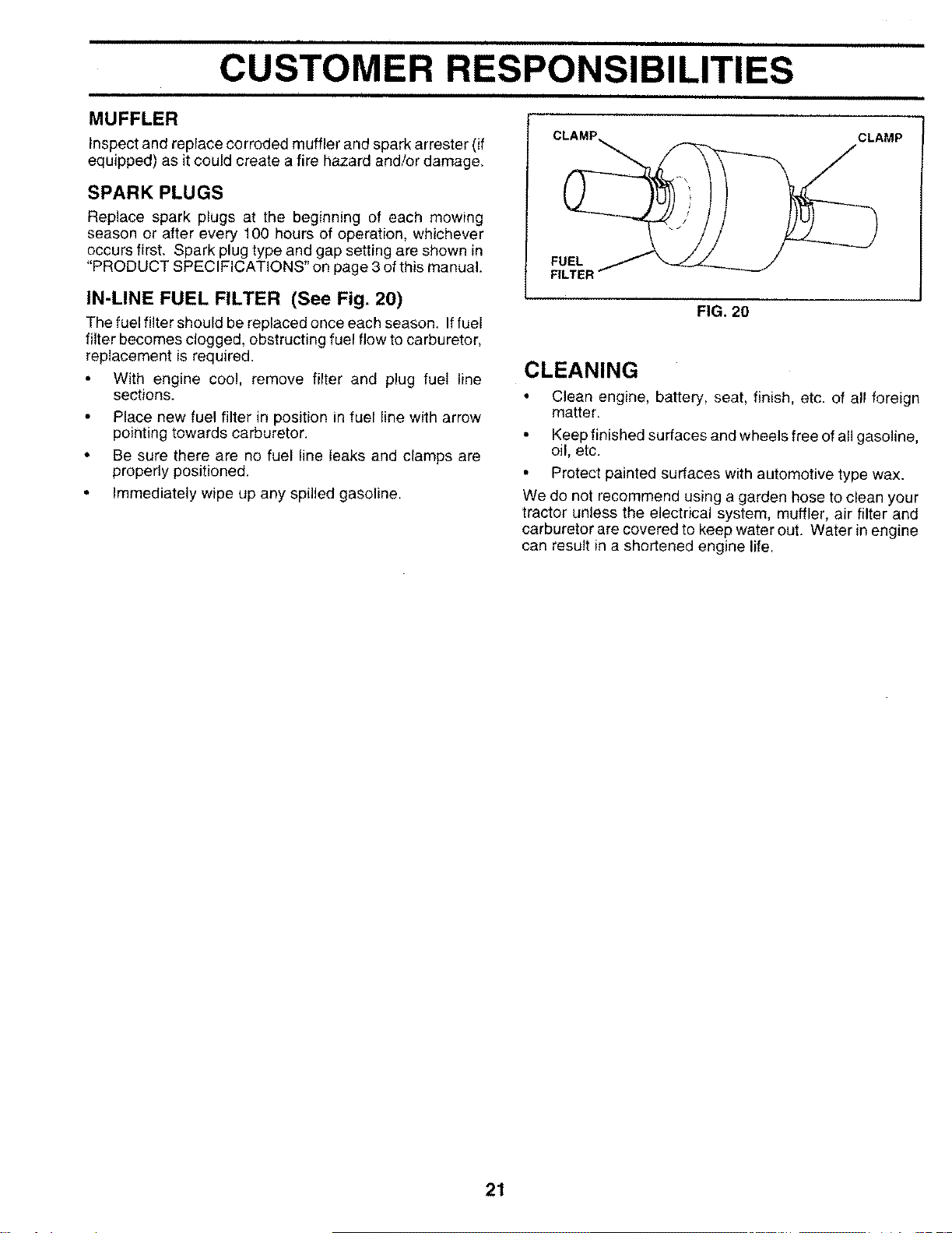
IN-LINE FUEL FILTER (See Fig. 20)
The fuel filter should be replaced once each season. If fuel
filter becomes clogged, obstructing fuel flow to carburetor,
replacement is required.
• With engine coo!, remove filter and plug fuel line
sections.
Place new fuel filter in position in fuel line with arrow
pointing towards carburetor.
Be sure there are no fuel line leaks and clamps are
properly positioned.
Immediately wipe up any spilled gasoline.
FUEL
FILTEI
CLEANING
ii
CLAMP
FIG. 20
• Clean engine, battery, seat, finish, etc. of all foreign
matter.
•Keep finished surfaces and wheels free of all gasoline,
oil, etc.
• Protect painted surfaces with automotive type wax.
We do not recommend using a garden hose to clean your
tractor unless the electrical system, muffler, air filter and
carburetor are covered to keep water out. Water in engine
can result in a shortened engine life.
21
, ii SERVICE AND ADJUSTMENTS
CAUTION: BEFORE PERFORMING ANY SERVICE OR ADJUSTMENTS:
•Depress clutch/brake pedal fully and set parking brake.
•Place motion control lever in neutral (N) position.
•Place attachment clutch in "DISENGAGED" position.
•Turn ignition key "OFF" and remove key.
•Make sure the blades and all moving parts have completely stopped,
• Disconnect spark plug wire from spark plug and place wire where itcannot come in contact with
plug.
TRACTOR
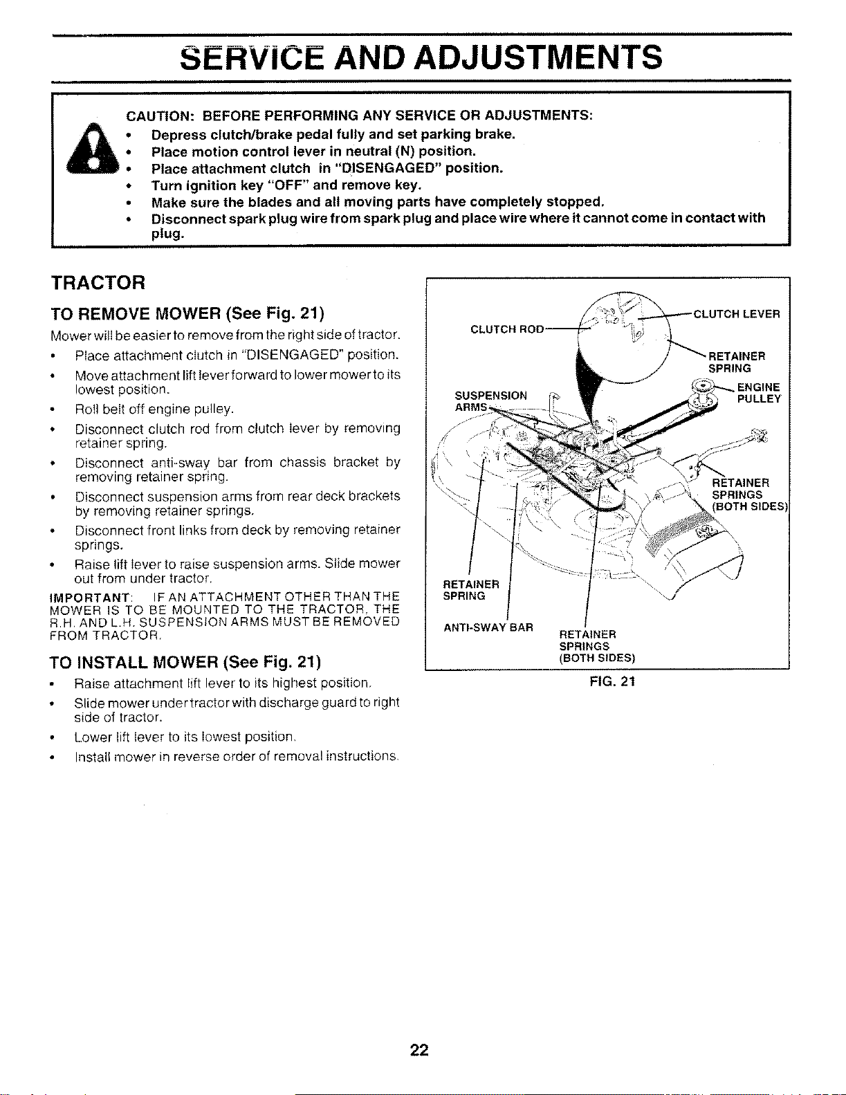
TO REMOVE MOWER (See Fig. 21)
Mower will be easier to remove from the right side oftractor.
• Place attachment clutch in "DISENGAGED" position.
Move attachment lift lever forward to lower mower to its
lowest position.
Roll belt off engine pulley.
• Disconnect clutch rod from clutch lever by removing
retainer spring.
• Disconnect anti-sway bar from chassis bracket by
removing retainer spring.
• Disconnect suspension arms from rear deck brackets
by removing retainer springs.
Disconnect front links from deck by removing retainer
springs.
• Raise lift lever to raise suspension arms. Slide mower
out from under tractor.
IMPORTANT: IF AN ATTACHMENT OTHER THAN THE
MOWER IS TO BE MOUNTED TO THE TRACTOR. THE
R.H. AND L.H. SUSPENSION ARMS MUST BE REMOVED
FROM TRACTOR.
TO INSTALL MOWER (See Fig. 21)
Raise attachment lift lever to its highest position,
Slide mower under tractor with discharge guard to right
side of tractor.
Lower lift lever to its lowest position,
Install mower in reverse order of removal instructions.
RETAINER
SPRING
ANTI-SWAY BAR RETAINER
SPRINGS
(BOTH SIDES)
FIG. 21
22
SERVICE AND ADJUSTMENTS
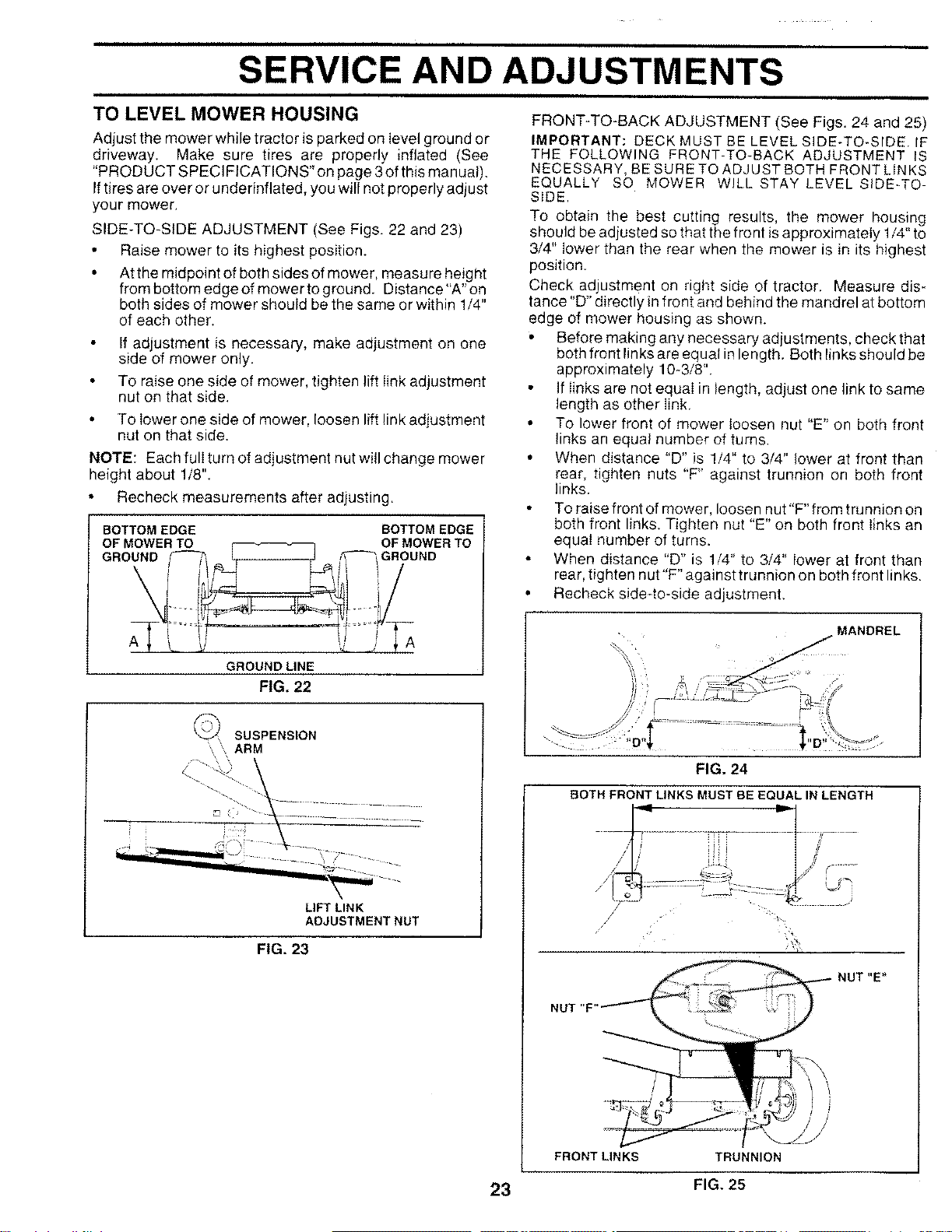
TO LEVEL MOWER HOUSING FRONT-TO-BACK ADJUSTMENT (See Figs. 24 and 25)
Adjust the mower while tractor is parked on level ground or
driveway. Make sure tires are properly inflated (See
"PROD UCT SPECIFICATIONS" on page 3 of this manual).
Iftires are over or underinflated, you will not properly adjust
your mower.
SIDE-TO-SIDE ADJUSTMENT (See Figs. 22 and 23)
•Raise mower to its highest position.
• Atthe midpoint of both sides of mower, measure height
from bottom edge of mower to ground. Distance"A" on
both sides of mower should be the same or within 1/4"
of each other.
If adjustment is necessary, make adjustment on one
side of mower only.
To raise one side of mower, tighten lift link adjustment
nut on that side.
To lower one side of mower, loosen lift link adjustment
nut on that side.
NOTE: Each full turn of adjustment nut will change mower
height about 1/8".
• Recheck measurements after adjusting.
BOTTOM EDGE BOTTOM EDGE
OF MOWER TO r • OF MOWER TO
GROUND f--_, L J ,_,GROUND
GROUND LINE
IMPORTANT: DECK MUST BE LEVEL SIDE-TO-SIDE. IF
THE FOLLOWING FRONT-TO-BACK ADJUSTMENT IS
NECESSARY, BE SURETOADJUSTBOTH FRONT LINKS
EQUALLY SO MOWER WILL STAY LEVEL SIDE-TO-
SIDE.
To obtain the best cutting results, the mower housing
should be adjusted so that the front is approximately 1/4" to
3/4" lower than the rear when the mower is in its highest
position.
Check adjustment on right side of tractor. Measure dis*
tance "D" directly in front and behind the mandrel at bottom
edge of mower housing as shown.
• Before making any necessary adjustments, check that
both front links are equal in length. Both links should be
approximately 10-3/8".
If links are not equal in length, adjust one link to same
length as other link.
• To lower front of mower loosen nut "E" on both front
links an equal number of turns.
• When distance "D" is 1/4" to 3/4" lower at front than
rear, tighten nuts "F' against trunnion on both front
links.
• Toraisefrontofmower, loosennut"F"fromtrunnionon
both front links. Tighten nut "E" on both front links an
equal number of turns.
When distance 'D" is 1/4" to 3/4" lower at front than
rear, tighten nut"F" against trunnion on both front links.
• Recheck side4o-side adjustment•
FIG. 22
SUSPENSION
'' ARM
\\
i
LIFT LINK
ADJUSTMENT NUT
FIG. 23
FIG. 24
BOTH FRONT LINKS MUST BE EQUAL IN LENGTH
NUT "F
NUT "E'*
FRONT LINKS TRUNNION
23 FIG. 25
SERVICE AND ADJUSTMENTS
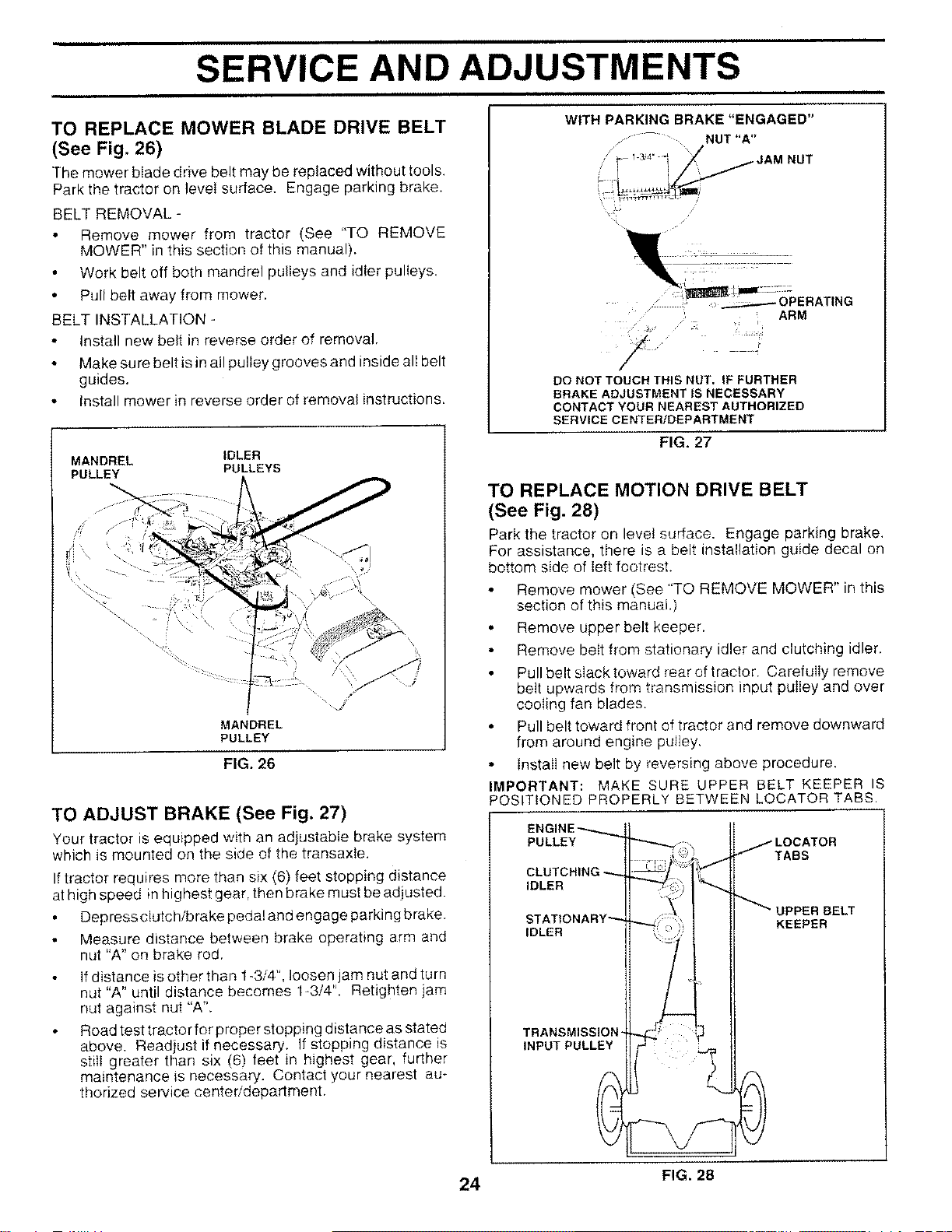
TO REPLACE MOWER BLADE DRIVE BELT
(See Fig. 26)
The mower blade drive belt may be replaced without tools.
Park the tractor on level surface. Engage parking brake.
BELT REMOVAL -
Remove mower from tractor (See "TO REMOVE
MOWER" in this section of this manual).
Work belt off both mandrel pulleys and idler pulleys.
Pull belt away from mower.
BELT INSTALLATION
Install new belt in reverse order of removal.
Make sure belt is in all pulley grooves and inside all belt
guides.
• Install mower in reverse order of removal instructions.
MANDREL IDLER
PULLEY PULLEYS
/,r /
MANDREL
PULLEY
FIG. 26
TO ADJUST BRAKE (See Fig. 27)
Your tractor is equipped with an adjustable brake system
which is mounted on the side of the transaxIe.
If tractor requires more than six (6) feet stopping distance
at high speed in highest gear, then brake must be adjusted.
Depress clutch/b rake pedal and engage parking brake.
Measure distance between brake operating arm and
nut "A" on brake rod.
If distance is other than t _3/4",loosen jam nut and turn
nut "A" until distance becomes 1_3/4". Retighten jam
nut against nut "A".
Road test tractor for proper stopping distance as stated
above. Readjust if necessary. If stopping distance is
still greater than six (6) feet in highest gear, further
maintenance _snecessary. Contact your nearest au-
thorized service center/department.
WITH PARKING BRAKE "ENGAGED"
..... NUT "A"
/\
. _ ' [ ARM
.J
DO NOTTOUCHTHISNUT. IFFURTHER
BRAKE ADJUSTMENTtS NECESSARY
CONTACT YOUR NEAREST AUTHORIZED
SERVICE CENTER/DEPARTMENT
FIG. 27
TO REPLACE MOTION DRIVE BELT
(See Fig. 28)
Park the tractor on level surface. Engage parking brake.
For assistance, there is a belt installation guide decal on
bottom side of left footrest.
Remove mower (See "TO REMOVE MOWER" in this
section of this manual.)
° Remove upper belt keeper.
Remove belt from stationary idler and clutching idler.
Pull belt slack toward rear of tractor. Carefully remove
belt upwards from transmission input pulley and over
cooling fan blades.
• Pull belt toward front of tractor and remove downward
from around engine pulley,
° Install new belt by reversing above procedure.
IMPORTANT: MAKE SURE UPPER BELT KEEPER IS
POSITIONED PROPERLY BETWEEN LOCATOR TABS.
ENGINE_
PULLEY _
CLUTCH
,DLER I[- 'i" /'"
S AT,ONARY''
IDLERIARY /
LOCATOR
TABS
_UPPER BELT
KEEPER
24 FIG. 28
SERVICE AND ADJUSTMENTS
TO ADJUST STEERING WHEEL ALIGNMENT
TO ADJUST MOTION CONTROL LEVER (See
Fig. 29)
The motion control lever has been preset at the factory and
adjustment should not be necessary.
If for any reason the motion control lever will not hold its
position while at a selected speed, it may be adjusted at the
friction pack located on the right side of transmission.
• Park tractor on level surface. Stop tractor by turning
ignition key to "OFF" position, and engage parking
brake.
Adjust motion control lever by tightening adjustment
Iocknut one half (1/2) turn.
NOTE: If for any reason the effort to move the motion
control lever becomes too excessive, reverse the above
adjustment procedure by loosening Iocknut 1/4 to 1/2 turn.
Road test tractor after adjustment and repeat procedure if
necessa_.
TRANSMISSION REMOVAL/REPLACEMENT
Should your transmission require removal for service or
replacement, it should be purged after reinstallation and
before operating the tractor. See "PURGE TRANSMIS-
SION" in the Operation section of this manual,
ADJUSTMENT
LOCKNUT
FIG. 29
If steering wheel crossbars are not horizontal (left to right)
when wheels are positioned straightforward, remove steer-
ing wheel and reassemble per instructions in the Assembly
section of this manual.
FRONT WHEEL TOE-IN/CAMBER
The front wheel toe-in and camber are not adjustable on
your tractor. If damage has occurred to affect the front
wheel toe-in or camber, contact your nearest authorized
service center/department.
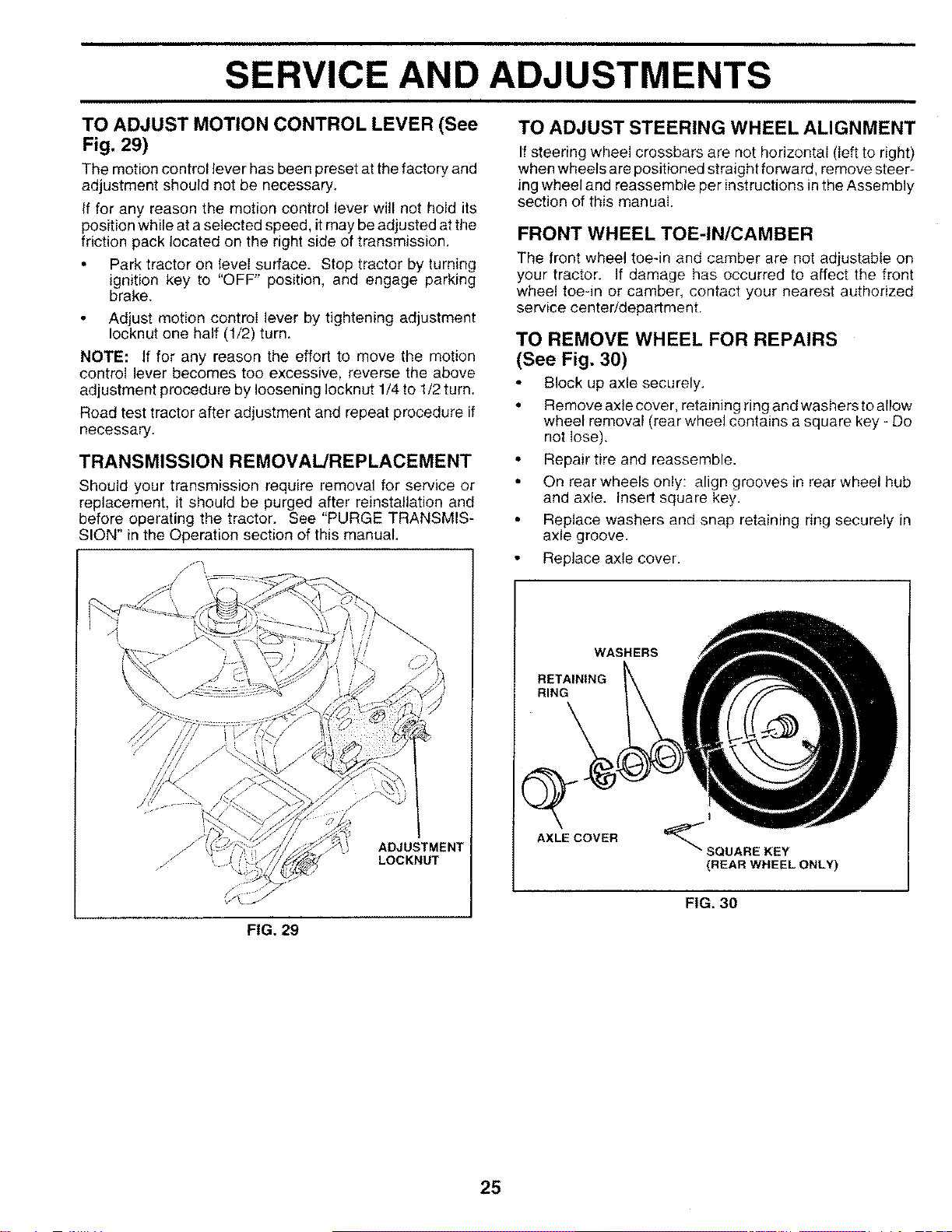
TO REMOVE WHEEL FOR REPAIRS
(See Fig. 30)
Block up axle securely.
° Remove axle cover, retaining ring and washers to allow
wheel removal (rear wheel contains a square key - Do
not lose).
• Repair tire and reassemble•
• On rear wheels only: align grooves in rear wheel hub
and axle. Insert square key.
• Replace washers and snap retaining ring securely in
axle groove.
• Replace axle cover.
WASHERS
RETAINING
RING
Q
AXLE COVER
I
"_"SQUARE KEY
(REAR WHEEL ONLY)
FIG. 30
25
SERVICE AND ADJUSTMENTS
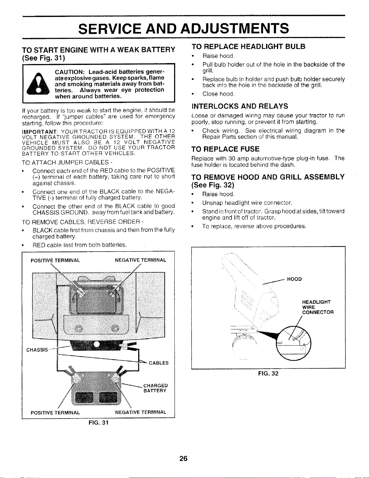
TO START ENGINE WITH A WEAK BATTERY
See Fig. 31)
CAUTION: Lead-acid batteries gener-
ate explosivegases, Keep sparks, flame
and smoking materials away from bat-
teries. Always wear eye protection
when around batteries.
If your battery is too weak to start the engine, it should be
recharged. If "jumper cables" are used for emergency
starting, follow this procedure:
IMPORTANT: YOUR TRACTOR IS EQUIPPED WITH A 12
VOLT NEGATIVE GROUNDED SYSTEM. THE OTHER
VEHICLE MUST ALSO BE A 12 VOLT NEGATIVE
GROUNDED SYSTEM. DO NOT USE YOUR TRACTOR
BATTERY TO START OTHER VEHICLES.
TO ATTACH JUMPER CABLES ÷
Connect each end of the RED cable to the POSITIVE
(÷) terminal of each battery, taking care not to short
against chassis.
Connect one end of the BLACK cable to the NEGA-
TIVE (-) terminal of fully charged battery.
• Connect the other end of the BLACK cable to good
CHASSIS GROUND. away from fuel tank and battery.
TO REMOVE CABLES, REVERSE ORDER -
• BLACK cable first from chassis and then from the fully
charged battery.
• RED cable last from both batteries.
TO REPLACE HEADLIGHT BULB
Raise hood.
• Pull bulb holder out of the hole in the backside of the
grill.
° Replace bulb in holder and push bulb holder securely
back into the hole in the backside of the grill.
Close hood.
INTERLOCKS AND RELAYS
Loose or damaged wiring may cause your tractor to run
poorly, step running, or prevent it from starting.
Check wiring. See electrical wiring diagram in the
Repair Parts section of this manual.
TO REPLACE FUSE
Replace with 30 amp automotive-type plug-in fuse. The
fuse holder is located behind the dash.
TO REMOVE HOOD AND GRILL ASSEMBLY
(See Fig. 32)
Raise hood.
Unsnap headlight wire connector.
• Stand in front of tractor. Grasp hood at sides, tilt toward
engine and Iift off of tractor.
To replace, reverse above procedures.
POSITIVE TERMINAL NEGATIVE TERMINAL
CHARGED
BATTERY
POSITIVE TERMINAL NEGATIVE TERMINAL
FIG. 31
_HOOD
HEADLIGHT
WIRE
CONNECTOR
FIG. 32
26
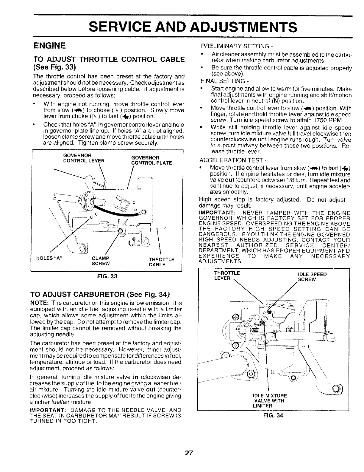
SERVICE AND ADJUSTMENTS
ENGINE PRELIMINARY SETTING-
TO ADJUST THROTTLE CONTROL CABLE
(See Fig. 33)
The throttle control has been preset at the factory and
adjustment should not be necessary. Check adjustment as
described below before loosening cable. If adjustment is
necessary, proceed as follows:
With engine not running, move throttle control lever
from slow (_l,) to choke (1\i) position. Slowly move
lever from choke (IX!) to fast (,_) position.
Checkthat holes "A" in governor controI lever and hole
in governor plate I!ne-up. tf holes "A" are not aligned,
loosen clamp screw and move throttle cable until holes
are aligned, Tighten clamp screw securely.
GOVERNOR
CONTROLLEVER GOVERNOR
CONTROLPLATE
\\
o
HOLES"A" CLAMP THROTTLE
SCREW CABLE
FIG. 33
TO ADJUST CARBURETOR (See Fig. 34)
NOTE: The carburetor on this engine islow emission. Itis
equipped with an idle fueI adjusting needle with a limiter
cap, which allows some adjustment within the limits al-
lowed by the cap. Do not attempt to remove the limiter cap.
The limiter cap cannot be removed without breaking the
adjusting needle.
The carburetor has been preset at the factory and adjust-
ment should not be necessary. However, minor adjust-
ment may be required tocompensate for differences infuel,
temperature, altitude or load. If the carburetor does need
adjustment, proceed as follows:
In general, turning idle mixture valve in (clockwise) de-
creases the supply of fuel to the engine giving a Ieaner fuel/
air mixture. Turning the idle mixture valve out (counter-
clockwise) increases the supply of fuel to the engine giving
a richer fuel/air mixture.
IMPORTANT: DAMAGE TO THE NEEDLE VALVE AND
THE SEAT IN CARBURETOR MAY RESULT IF SCREW IS
TURNED IN TOO TIGHT.
Air cleaner assembly must be assembled to the carbu-
retor when making carburetor adjustments.
• Be sure the throttle control cable is adjusted properly
(see above).
FINAL SETTING -
• Start engine and allow to warm for five minutes, Make
final adjustments with engine running and shift/motion
control lever in neutral (N) position.
Move throttle control lever to slow (,_) position. With
finger, rotate and hold throttle iever against idle speed
screw. Turn idle speed screw to attain 1750 RPM.
While still holding throttle lever against idle speed
screw, tum idle mixture valve full travel clockwise then
counterclockwise until engine runs rough. Turn valve
to a point midway between those two positions. Re-
lease throttle lever.
ACCELERATION TEST -
• Move throttle controi lever from slow (,_) to fast (,f_)
position. If engine hesitates or dies, turn idle mixture
valveout (counterclockwise) 1/8turn. Repeattestand
continue to adjust, if necessary, until engine acceler-
ates smoothly.
High speed stop is factory adjusted. Do not adjust -
damage may result,
IMPORTANT: NEVER TAMPER WITH THE ENGINE
GOVERNOR, WHICH IS FACTORY SET FOR PROPER
ENGINE SPEED. OVERSPEEDING THE ENGINE ABOVE
THE FACTORY HiGH SPEED SETTING CAN BE
DANGEROUS. IF YOU THINK THE ENGINE-GOVERNED
HIGH SPEED NEEDS ADJUSTING, CONTACT YOUR
NEAREST AUTHORIZED SERVICE CENTER/
DEPARTMENT, WHICH HAS PROPER EQUIPMENT AND
EXPERIENCE TO MAKE ANY NECESSARY
ADJUSTMENTS.
THROTTLE IDLE SPEED
LEVER SCREW
\\
IDLE MIXTURE
VALVE WITH
LIMtTER
FIG. 34
27
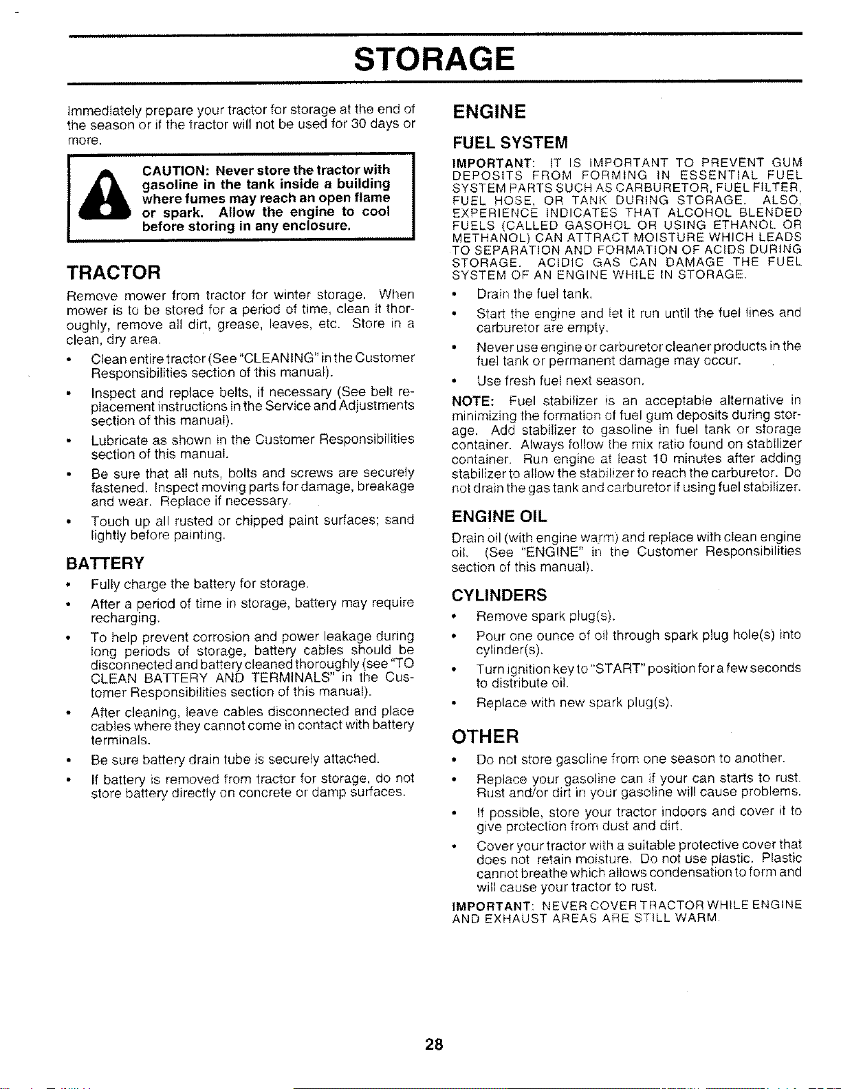
STORAGE
ENGINEImmediately prepare your tractor for storage at the end of
the season or if the tractor will not be used for 30 days or
more.
CAUTION: Never store the tractor with
gasoline in the tank inside a building
where fumes may reach an open flame
or spark. Allow the engine to cool
before storing in any enclosure.
TRACTOR
Remove mower from tractor for winter storage. When
mower is to be stored for a period of time, clean it thor-
oughly, remove all dirt, grease, leaves, etc. Store in a
clean, dry area.
Clean entire tractor (See "CLEANING" inthe Customer
Responsibilities section of this manual).
• Inspect and replace belts, if necessary (See belt re-
placement instructions in the Service and Adjustments
section of this manual).
Lubricate as shown in the Customer Responsibilities
section of this manual.
Be sure that ali nuts, bolts and screws are securely
fastened. Inspect moving parts for damage, breakage
and wear. Replace if necessary.
Touch up all rusted or chipped paint surfaces; sand
lightly before painting.
BATTERY
Fully charge the battery for storage.
After a period of time in storage, battery may require
recharging.
To help prevent corrosion and power leakage during
long periods of storage, battery cables should be
disconnected and battery cleaned thoroughly (see TQ
CLEAN BATTERY AND TERMINALS" in the Cus-
tomer Responsibilities section of this manuaI).
After cleaning, leave cables disconnected and place
cables where they cannot come in contact with battery
terminals.
Be sure battery drain tube is securely attached.
If battery is removed from tractor for storage, do not
store battery directly on concrete or damp surfaces.
FUEL SYSTEM
IMPORTANT: IT IS IMPORTANT TO PREVENT GUM
DEPOSITS FROM FORMING IN ESSENTIAL FUEL
SYSTEM PARTS SUCH AS CARBURETOR, FUEL FILTER,
FUEL HOSE, OR TANK DURING STORAGE. ALSO,
EXPERIENCE INDICATES THAT ALCOHOL BLENDED
FUELS (CALLED GASOHOL OR USING ETHANOL OR
METHANOL) CAN ATTRACT MOISTURE WHICH LEADS
TO SEPARATION AND FORMATION OF ACIDS DURING
STORAGE. ACIDIC GAS CAN DAMAGE THE FUEL
SYSTEM OF AN ENGINE WHILE IN STORAGE.
Drain the fuel tank.
I
Start the engine and tet it run until the fuel lines and
carburetor are empty.
Never use engine or carburetor cleaner products in the
fue; tank or permanent damage may occur.
Use fresh fueI next season.
NOTE: Fuel stabilizer is an acceptable alternative in
minimizing the formation of fuel gum deposits during stor-
age. Add stabilizer to gasoline in fuel tank or storage
container. Always follow the mix ratio found on stabilizer
container. Run engine at least !0 minutes after adding
stabilizer to aItow the stabilizer to reach the carburetor. Do
not drain the gas tank and carburetor ifusing fuel stabilizer.
ENGINE OIL
Drain oil (with engine warm) and replace with cIean engine
oil. (See 'ENGINE' in the Customer Responsibilities
section of this manual).
CYLINDERS
• Remove spark plug(s).
. Pour one ounce of oil through spark plug hole(s) into
cylinder(s).
Turn ignition key to "START" position for a few seconds
to distribute oil.
Replace with new spark plug(s).
OTHER
• Do not store gasoline from one season to another.
Replace your gasoline can if your can starts to rust.
Rust and/or dirt in your gasoline wil! cause problems.
If possible, store your tractor indoors and cover it to
give protection from dust and dirt.
Cover your tractor with a suitable protective cover that
does not retain moisture. Do not use plastic. Plastic
cannot breathe which allows condensation to form and
will cause your tractor to rust.
IMPORTANT: NEVER COVER TRACTOR WHILE ENGINE
AND EXHAUST AREAS ARE STILL WARM.
28

ii ii TROUBLESHOOTING POINTS
i
PROBLEM
Will not start
Herd to start
Engine will not turn over
Engine clicks but will not
start
Loss of power
Excessive vibration
CAUSE
1. Out of fuel.
2. Engine not "CHOKED" properiy.
3, Engine flooded.
4. Bad spark plug,
5 Dirty air filter
6 Dirty fuel filter,
7. Water in fuel
8. Loose or damaged wiring
9 Carburetor out of adjustment
10 Engine valves out of adjustment
1. Dirty air fiIter
2 Bad spark plug.
3, Weak or dead battery.
4. Dirty fuel filter,
5 Stale or dirty fuel.
& Loose or damaged winng.
7. Carburetor out of adjustment
8, Engine valves out of adjustment.
1. Clutch/brake pedal not depressed.
2. Attachment clutch is engaged.
3, Weak or dead battery.
4 Blown fuse.
5. Corroded battery terminals.
6 Loose or damaged wiring.
7, Faulty ignition switch.
8. Faulty solenoid or starter.
9. Faulty operator presence swkch(es).
I Weak or dead battery
2 Corroded battery terminals.
3 Loose or damaged wiring,
4 Faulty solenoid or starter.
1 Cutting too much grass/too fast
2, Throttle in 'CHOKE" position
3. Buitd_up of grass, !eaves and trash under mower.
4 Dirb/air filter
5 Low oil level!dirty oil
6 Faulb7 spark plug.
7 Dirty rue! filter,
8. Sta!e or dirty fuel.
g Water in fuel
10 Spark p!ug wire loose
11 Dirty engine air screen!fins.
12 Dirty/clogged muffler
13 Loose or damaged wiring.
14 Carburetor out of adjustment
15 Engine valves out of adjustment
1 Worn. bent or loose blade
2 Bent b!ade mandrel
3 Loose/damaged part(s).
CORRECTION
1, Fi!l fuel tank
2. See "TO START ENGINE" in Operation section.
3. Wait several minutes before attempting to start.
4. Reptace spark plug
5 Clean/replace air filter.
6. Rep!ace fuei filter
7. Drain fuel tank and carburetor, refill tank with fresh
gasoline and replace fuel filter.
8 Check all wiring,
9, Contact an authorized service center!departnnent.
10. Contact an authorized service center/department.
1 Clean!replace air filter.
2 Replace spark plug,
3. Recharge or replace battery.
4 Replace fuel filter.
5. Drain fuel tank and refi!l with fresh gasoIine.
6 Check all wiring
7 Contact an authorized service center/department,
8, Contact an authorized service center/department.
1. Depress clutch/brake pedal.
2. Disengage attachment dutch,
3. Recharge or replace battery,
4 Replace fuse.
5, Clean battery terminals.
6. Check al! wiring,
7, ChecWreplace ignition switch,
8. Check/replace solenoid or starter.
9 Contact an authorized service center/department.
1. Recharge or replace batten/,
2. Clean battery terminals.
3 Check atl wiring.
4 ChecWrepiace sotenoid or starter.
1 Set in "Higher Cut" position/reduce speed.
2 Adjust throttle control
3 Clean underside of mower housing
4 C}ean/repiace air filter.
5 Check oil level/change oii
6. Clean and regap or change spark plug,
7 Replace fuel filter.
8 Drain fuel tank and refill with fresh gasoline
9 Drain fuel tank and carburetor, refitf tank with fresh
gasoline and replace fuel tilter.
I0 Connect and tighten spark p_ug wire
t 1 Clean engine air screen/fins.
12. Clean/rep]ace muttler
13 Check all wiring
14 Contact an authorized service center/deparlment
15. Contact an authorized service center/department,
i Replace blade Tighten blade bolt
2 Replace blade mandrel.
3 Tighten loose part(s). Replace damaged parts,
29

TROUBLESHOOTING POINTS
PROBLEM CAUSE CORRECTION
Engine continues to run
when operator leaves seat
with attachment clutch
engaged
Poorcut-uneven
Mower blades will not
rotate
Poor grass discharge
Headlight(s) not working
(if so equipped)
Battery will not charge
Loss of drive
Engine "backfires"
when turning engine
*'OFF"
1 Fautb/operator-safety presence control system.
1 Worn, bent or loose blade.
2 Mower deck not level.
3 Buildup of grass, leaves, and trash under mower.
4. Bent blade mandrel
5. Clogged mower deck vent holes from buildup of
grass, leaves, and trash around mandrels,
1. Obstruction in clutch mechanism.
2. Worn/damaged mower drive belt.
3 Frozen idler pulley.
4. Frozen blade mandrel
1 Engine speed too slow.
2 Travel speed too fast.
3 Wet grass.
4, Mower deck not level
5. Low/uneven tire air pressure
6 Worn, bent or loose blade.
7 Buildup of grass, reaves and trash under mower.
8 Mower drive belt worn.
9 Blades improperly installed.
10. Improper blades used.
!1, Clogged mower deck vent holes from buildup of
grass, leaves, and trash around mandrels.
1 Switch is "OFF".
2. Butb(s) burned out
3 Faulty light switch.
4 Loose or damaged wiring
5 Blown fuse.
1. Bad battery celt(s)
2 Poor cable connections.
3 Faulty regulator (if so equipped)
4. Faulty alternator
1 Freewheel control irl "disengaged" position.
2 Motion drive belt worn, damaged, or broken
3 Air trapped in transmission dunng shipment
or servicing,
Engine throttle control not set at "SLOW"
position for 30 seconds before stopping engine
1 Check wiring, switches and connections. If not
corrected, contact an authorized service center/
department.
1. Repiace blade Tighten blade bolt.
2, Level mower deck.
3. Clean underside of mower housing.
4, Repiace blade mandrel.
5. Clean around mandrels to open vent holes.
1 Remove obstruction,
2 Replace mower drive belt
3 Repiace idler pultey.
4 Replace blade mandrel,
1. Place throttle co_trol in 'FAST" position.
2. Shift to slower speed.
3 A!tr_w grass to dry before mowing.
4 Level mower deck.
5. Check tires for proper air pressure.
6. Replace/sharpen blade. Tighten blade bolt.
7. Clean underside of mower housing.
8. Replace mower drive belt.
9. Reinstall blades sharp edge down.
10. Replace with biades iisted in this manual
11 Clean around mandrels to open vent holes.
1, Turn switch "ON",
2 Replace bulb(s)
3 ChecWreplaee Jight switch.
4. Check wiring and connections.
5 Replace fuse.
t Replace battery
2. Check/clean all connections
3 Replace regulator
4 Replace alternator,
1 Place freewheel control in "engaged' position.
2 Replace motion drive belt
3, Purge transmission
! Move throttle co_trol to "SLOW" position and allow
to idle for 30 seco_ds before stopping engine,
3O
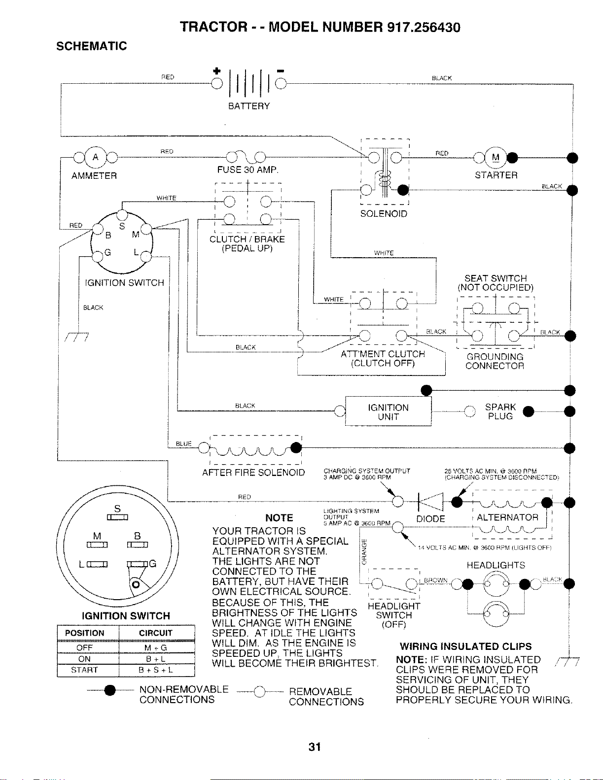
SCHEMATIC TRACTOR - - MODEL NUMBER 917.256430
!
L
RED
_ RED
AMMETER
WHITE
I
I
i RED S
)G L(
i SLAcKIGNITION SWITCH [
BATTERY
FUSE 30 AMP.
/
• -- _-T .....
&U CH/BRA E
(PEDAL UP)
BLACK
SOLENOID
STARTER
SEAT SWITCH
(NOT OCCUPIED)
BLACK
RED
WHITE ]
GROUNDING
CONNECTOR
" I
;_('_ I B', ACK
ATT'MENT CLUTCH _"
CLUTCH OFF) J
BLACK
POSITION
OFF
ON
START
B_CK
I
i BLUE
_LJLJLJLJ_L# _'
I
AFTER FIRE SOLENOID
RED
IGNITION SPARK O---41
UNIT PLUG i
CHARGING SYSTEM OUTPUT
3 AMP DC @ 3600 RPM 28 VOLTS AC MIN @ 3600 RPM
(CHARGING SYSTEM DISCONNECTED I
.... I
LIGHTING SYSTEM
NOTE OUTPUT DIODE ALTERNATOR
YOUR TRACTOR IS 6AMPAC @_'*_,3,_PM_
EQUIPPED WITH A SPECIAL I_ "-, , ,
ALTERNATOR SYSTEM I_ _4 VOLTS AC MiN @ 3600 RPM (LIGHTS OEI}
THE LIGHTS ARE NOT I_ HFAIblIGNT£
CONNECTED TO THE , - ........
IGNITION SWITCH
CIRCUIT
M+G
B+L
B+S-_L
NON-REMOVABLE ---_j-_-_ REMOVABLE
CONNECTIONS CONNECTIONS
BATTERY, BUT HAVE THEIR
OWN ELECTRICAL SOURCE.
BECAUSE OF THIS, THE
BRIGHTNESS OF THE LIGHTS
WILL CHANGE WITH ENGINE
SPEED. AT IDLE THE LIGHTS
WILL DIM. AS THE ENGINE IS
SPEEDED UP. THE LIGHTS
WILL BECOME THEIR BRIGHTEST.
t I
HEADLIGHT
SWITCH
(OFF)
WIRING INSULATED CLIPS
NOTE: IF WIRING INSULATED
CLIPS WERE REMOVED FOR
SERVICING OF UNIT, THEY
SHOULD BE REPLACED TO
PROPERLY SECURE YOUR WIRING.
/t/
31

REPAIR PARTSTRACTOR - - MODEL NUMBER 917,256430
ELECTRICAL
19
25
26 4O
36
\
\
\
15 \\:\ \
8/
45
6
/
52
29 \
32
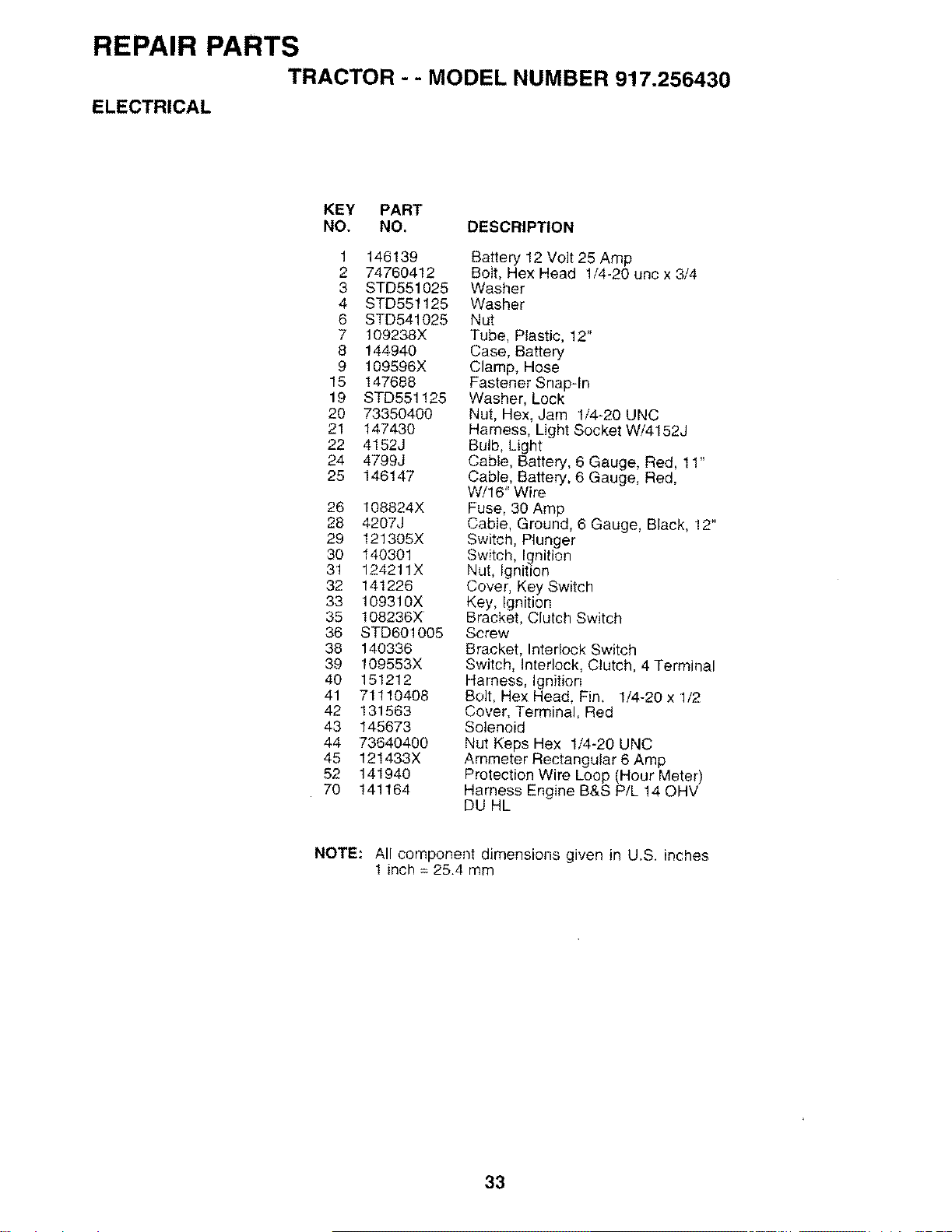
REPAIR PARTSTRACTOR --MODEL NUMBER 917.256430
ELECTRICAL
KEY PART
NO. NO, DESCRIPTION
1 146139
2 74760412
3 STD551025
4 STD551125
6 STD541025
7 109238X
8 144940
9 109596X
15 147688
19 STD551125
20 73350400
21 147430
22 4152J
24 4799J
25 146147
26 108824X
28 4207J
29 121305X
30 140301
31 124211X
32 141226
33 1093!0X
38 108236X
36 STD60!005
38 140336
39 109553X
40 151212
41 71110408
42 131563
43 145673
44 73640400
45 121433X
52 141940
70 141164
Battery 12 Volt 25 Amp
Bolt, Hex Head 1/4-20 unc x 3/4
Washer
Washer
Nut
Tube, Plastic, 12"
Case, Battery
Clamp, Hose
Fastener Snap-In
Washer, Lock
Nut, Hex, Jam 1/4-20 UNC
Harness, Light Socket W/4152J
Bulb, Light
Cable, Battery, 6 Gauge, Red, 11"
Cable, Battery, 6 Gauge, Red,
W/16" Wire
Fuse, 30 Amp
Cable, Ground, 6 Gauge, Black, 12"
Switch, Plunger
Switch, Ignition
Nut, Ignition
Cover, Key Switch
Key, Ignition
Bracket, Clutch Switch
Screw
Bracket, Interlock Switch
Switch, Interlock, Clutch, 4 Terminal
Harness, Ignition
Bolt, Hex Head, Fin, 1/4-20 x 1/2
Cover, Terminal, Red
Solenoid
Nut Keps Hex 1/4-20 UNC
Ammeter Rectangular 6 Amp
Protection Wire Loop (Hour Meter)
Harness Engine B&S P!L !4 QHV
DU HL
NOTE: All component dimensions given in U.S. inches
1 inch : 25.4 mm
33
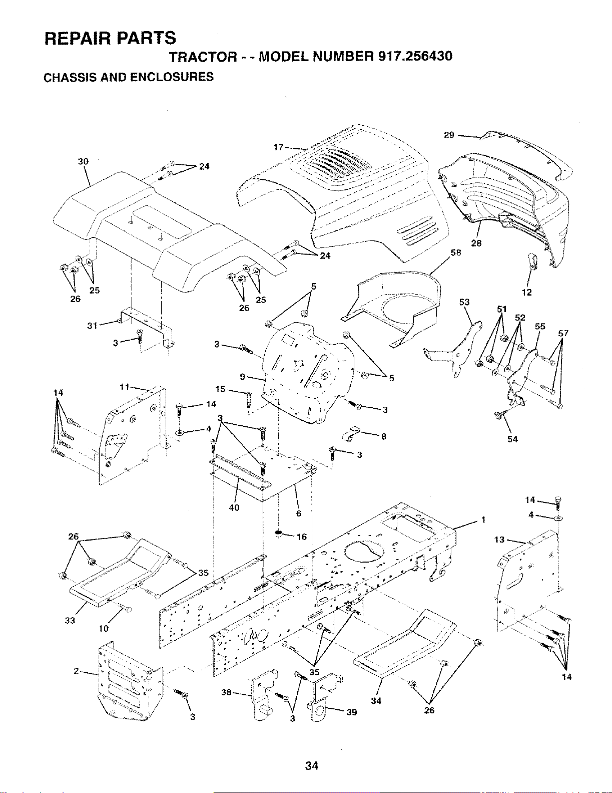
REPAIR PARTS
TRACTOR - -MODEL NUMBER 917.256430
CHASSIS AND ENCLOSURES
25
26
26
33 10
3
14
54
4O
34 26
4_
"i
34
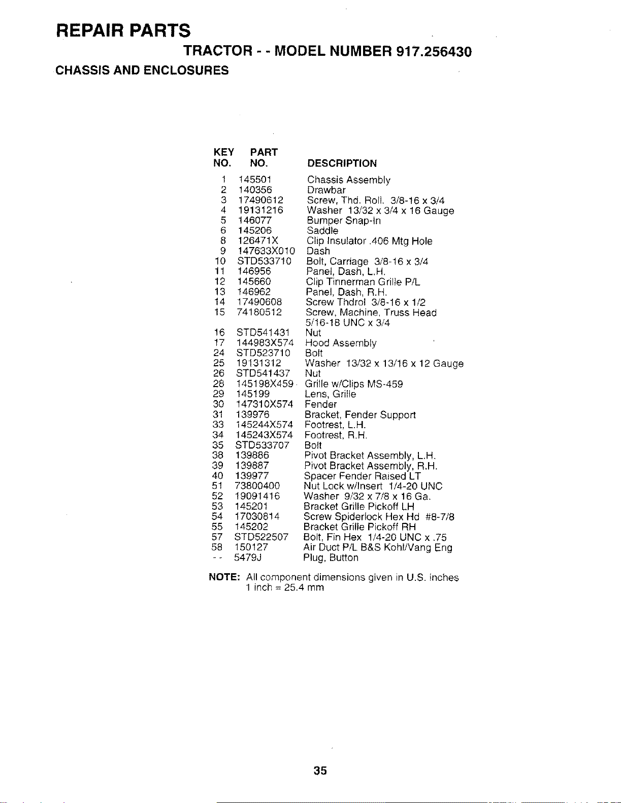
REPAIR PARTSTRACTOR - - MODEL NUMBER 917.256430
CHASSIS AND ENCLOSURES
KEY PART
NO. NO. DESCRIPTION
1 145501
2 140356
3 17490612
4 19131216
5 146077
6 145206
8 126471X
9 !47633X010
10 STD533710
11 146956
12 145660
13 146962
14 17490608
15 74180512
16 STD541431
17 144983X574
24 STD523710
25 19131312
26 STD541437
28 145198X459
29 145199
30 147310X574
31 139976
33 145244X574
34 145243X574
35 STD533707
38 139886
39 139887
40 139977
51 73800400
52 19091416
53 145201
54 17030814
55 145202
57 STD522507
58 150127
-- 5479J
Chassis Assembly
Drawbar
Screw, Thd. Roll, 3/8-16 x 3/4
Washer 13/32 x 3/4 x 16 Gauge
Bumper Snap-In
Saddle
Clip Insulator .406 Mtg Hole
Dash
Bolt, Carriage 3/8-16 x 3/4
Panel, Dash, L,H,
Clip Tinnerman Grille P/L
Panel, Dash, R.H.
Screw Thdrol 3/8-16 x 1/2
Screw, Machine, Truss Head
5/16-18 UNC x 3/4
Nut
Hood Assembly
Bolt
Washer 13/32 x 13/16 × 12 Gauge
Nut
Grille w/Clips MS-459
Lens, Grille
Fender
Bracket, Fender Support
Footrest, LH.
Footrest, R.H.
Bolt
Pivot Bracket Assembly, L.H.
Pivot Bracket Assembly, R.H.
Spacer Fender Raised LT
Nut Lock w/Insert 1/4-20 UNC
Washer 9/32 x 7/8 x 16 Ga.
Bracket Grille Pickoff LH
Screw SpiderIock Hex Hd #8-7/8
Bracket Grille Pickoff RH
Bolt, Fin Hex 1/4-20 UNC x .75
Air Duct P/L B&S Kohl/Vang Eng
Plug, Button
NOTE: All component dimensions given in U.S. inches
1 inch = 25.4 mm
35
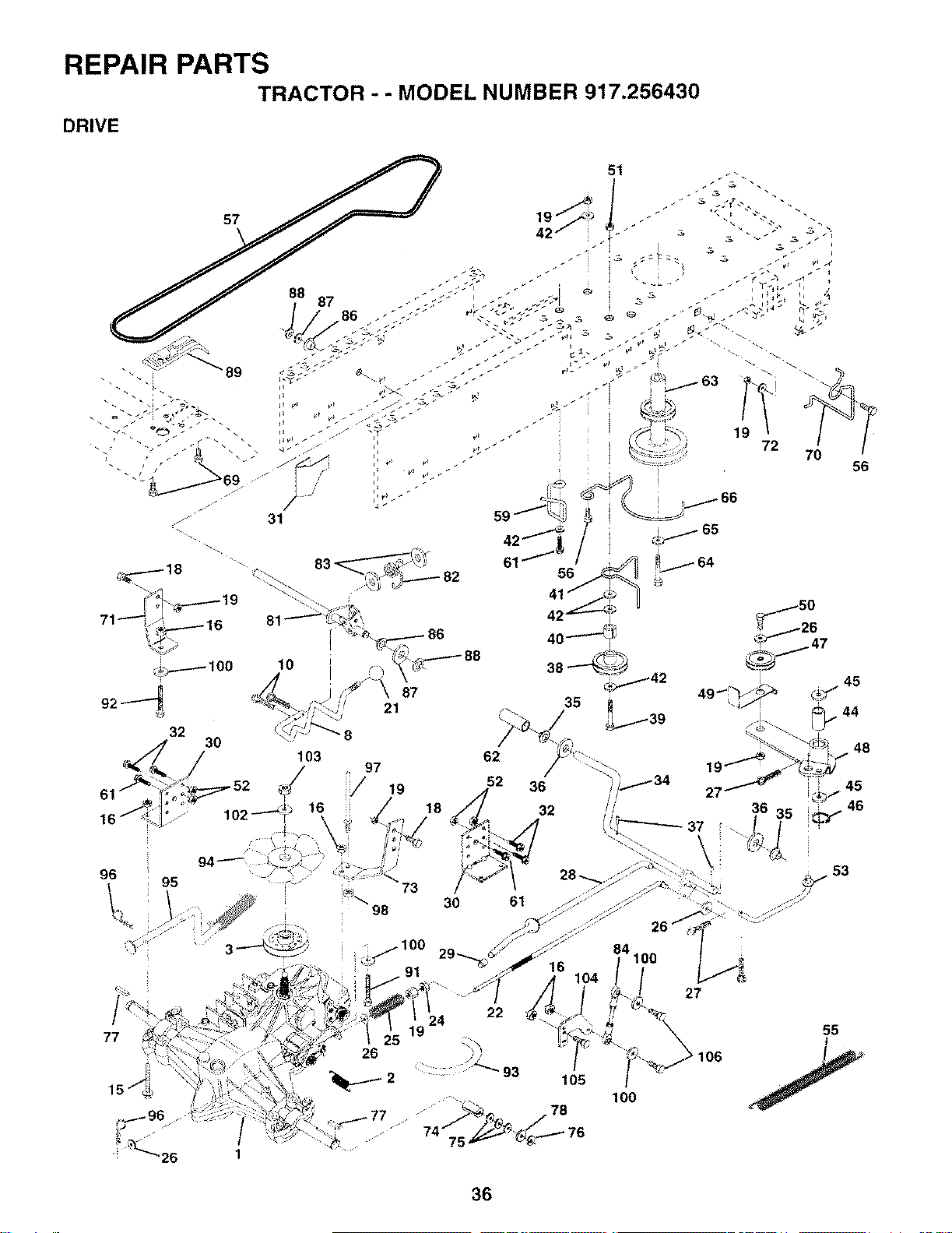
REPAIR PARTSTRACTOR - " MODEL NUMBER 917.256430
DRIVE
57
32
96 95
18
77
61
35
56
24
19
26
22
36
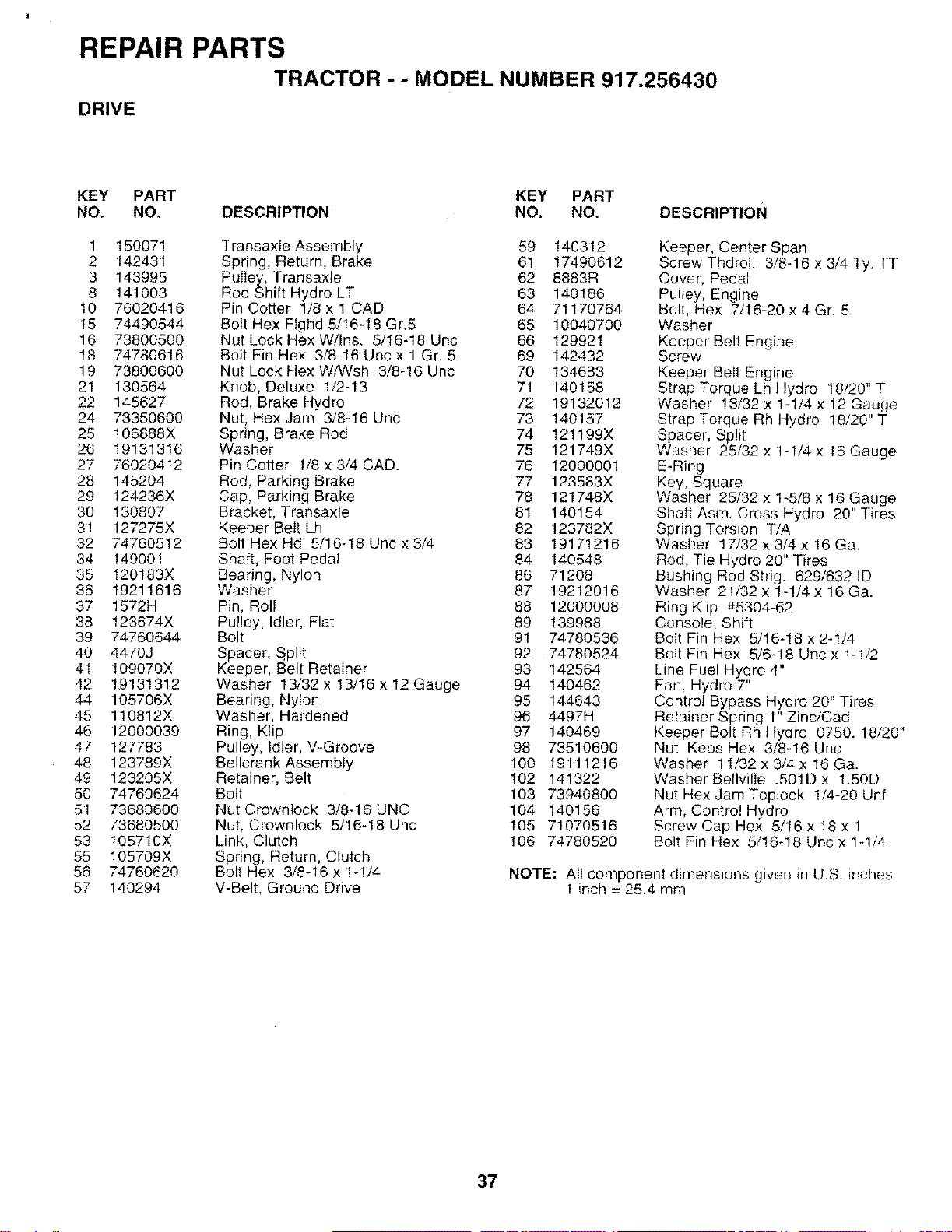
REPAIR PARTSTRACTOR --MODEL NUMBER 917.256430
DRIVE
KEY PART KEY PART
NO. NO, DESCRIPTION NO. NO. DESCRIPTION
1 150071
2 142431
3 143995
8 141003
10 76020416
15 74490544
16 73800500
18 74780616
19 73800600
21 130564
22 145627
24 73350600
25 106888X
26 19131316
27 76020412
28 145204
29 124236X
30 130807
31 127275X
32 74760512
34 149001
35 120183X
36 19211616
37 1572H
38 123674X
39 74760644
40 4470J
41 109070X
42 19131312
44 105706X
45 110812X
46 12000039
47 127783
48 123789X
49 123205X
50 74760624
51 73680600
52 73680500
53 105710X
55 105709X
56 74760620
57 140294
Transaxte Assembly 59 140312
Spring, Return, Brake 61 17490612
Pulley, Transaxle 62 8883R
Rod Shift Hydro LT 63 140186
Pin Cotter 1/8 x ! CAD 64 71170764
Bolt Hex Flghd 5/16-18 Gr.5 65 10040700
Nut Lock Hex W/Ins. 5/16-18 Unc 66 129921
Bolt Fin Hex 3/8-18 Unc x 1 Gr. 5 69 142432
Nut Lock Hex WiWsh 3/8-16 Unc 70 134683
Knob, Deluxe 1/2-13 71 140158
Rod, Brake Hydro 72 19132012
Nut, Hex Jam 3/8-16 Unc 73 140157
Spring, Brake Rod 74 121199X
Washer 75 121749X
Pin Cotter 1/8 x 3/4 CAD. 76 12000001
Rod, Parking Brake 77 123583X
Cap, Parking Brake 78 121748X
Bracket, Transaxle 81 140154
Keeper Belt Lh 82 123782X
Bolt Hex Hd 5/16-18 Unc x 3/4 83 19171216
Shaft, Foot Pedal 84 140548
Bearing, Nylon 86 71208
Washer 87 19212016
Pin, Roll 88 12000008
Pulley, Idler, Flat 89 139988
Bolt 91 74780536
Spacer, Split 92 74780524
Keeper, Belt Retainer 93 142564
Washer 13/32 x 13/16 x 12 Gauge 94 140462
Bearing, Nylon 95 144643
Washer, Hardened 96 4497H
Ring, Klip 97 140469
Pulley, Idler, V-Groove 98 73510600
Bellcrank Assembly 100 19111216
Retainer, Belt 102 141322
Bolt 103 73940800
Nut Crownlock 3/8-16 UNC 104 140156
Nut, Crownleck 5/16-18 Unc 105 71070516
Link, Clutch 106 74780520
Spring, Return, Clutch
Bolt Hex 3/8-16 x 1-1/4
V-Belt, Ground Drive
Keeper, Center Span
Screw Thdrol. 3/8-16 x 3/4 Ty. TT
Cover, Pedal
Pulley, Engine
Bolt, Hex 7/16-20 x 4 Gr. 5
Washer
Keeper Belt Engine
Screw
Keeper Belt Engine
Strap Torque Lh Hydro 18/20" T
Washer 13/32 x 1-1/4 x 12 Gauge
Strap Torque Rh Hydro 18/20" T
Spacer, Split
Washer 25/32 x 1-1/4 x 16 Gauge
E-Ring
Key, Square
Washer 25/32 x 1-5/8 x 16 Gauge
Shaft Asm. Cross Hydro 20" Tires
Spring Torsion TiA
Washer 17/32 x 3/4 x 16 Ga.
Rod, Tie Hydro 20" Tires
Bushing Rod Strig. 629/632 ID
Washer 21/32 x 1-1/4 x 16 Ga.
Ring Klip #5304-62
Console, Shift
Bolt Fin Hex 5/16-18 x 2-1/4
Bolt Fin Rex 5/6-18 Unc x 1-1/2
Line Fuel Hydro 4"
Fan. Hydro 7"
Control Bypass Hydro 20" Tires
Retainer Spring 1" Zinc/Cad
Keeper Bolt Rh Hydro 0750. 18/20"
Nut Keps Hex 3/8-16 Unc
Washer 11/32x3i4x16Ga.
Washer Bellvilie .50tD x 1.50D
Nut Hex Jam Toplock 1/4-20 Unf
Arm, Control Hydro
Screw Cap Hex 5/16 x 18 x 1
Bolt Fin Hex 5/!6-!8 Unc x 1-1/4
NOTE: All component dimensions given in U.S. inches
1 inch = 25.4 mm
37
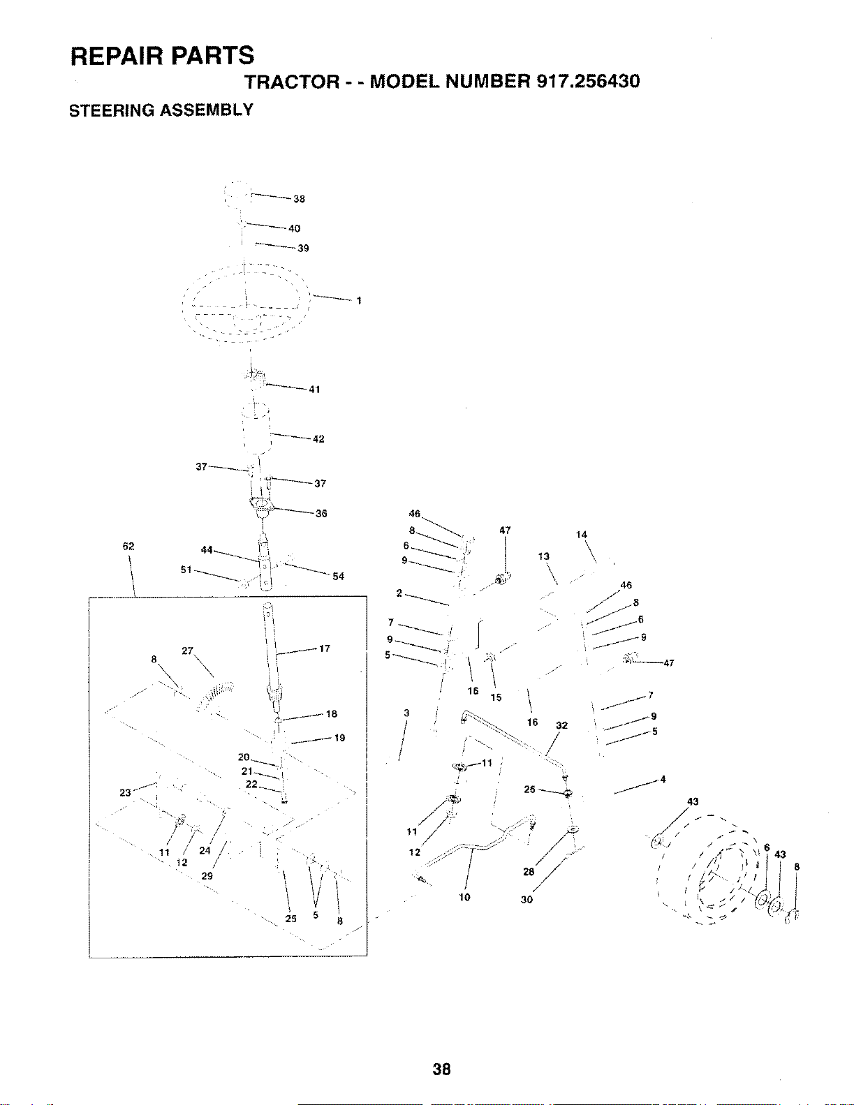
REPAIR PARTS
TRACTOR -- MODEL NUMBER 917.256430
STEERING ASSEMBLY
38
62
23 _J
11
• _41
"i _i¸_'---'--_ 37
46...
8 _ 47
44_ 6_ _
27 -_._ 17
j19
20_
22 __._
2'f
12
29
25 ;8
7
5:
!°15
J_
11 /
i
12
10
13
16 32
f
/
_4
26•_
,/
28 /
/
3O
14
46
8
i-j
j7 j9
j4 43
/\
/\1 6 43
// / ts i I 8
38
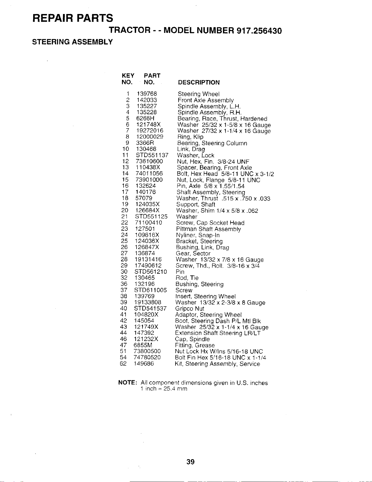
REPAIR PARTSTRACTOR - -MODEL NUMBER 917.256430
STEERING ASSEMBLY
KEY PART
NO. NO. DESCRIPTION
1 139768
2 142033
3 135227
4 135228
5 6266H
6 121748X
7 19272016
8 12000029
9 3366R
10 130468
11 STD551137
12 73610600
13 110438X
14 74011056
15 73901000
16 132624
17 140176
18 57079
19 124035X
20 126684X
21 STD551125
22 71100410
23 127501
24 109816X
25 124036X
26 126847X
27 136874
28 19131416
29 17490612
30 STD561210
32 130465
36 132196
37 STD611005
38 139769
39 1£133808
40 STD541537
41 104820X
42 145054
43 121749X
44 147392
46 121232X
47 6855M
51 73800500
54 74780520
62 149686
Steering Wheel
Front Axle Assembly
Spindle Assembly, L.H.
Spindle Assembly, R.H.
Bearing, Race, Thrust, Hardened
Washer 25/32 x 1-5/8 x 16 Gauge
Washer 27/32 x 1-1/4 x 16 Gauge
Ring, Klip
Bearing, Steering Column
Link, Drag
Washer, Lock
Nut, Hex, Fin. 3/8-24 UNF
Spacer, Bearing, Front Axle
Bolt, Hex Head 5/8-11 UNC x 3q/2
Nut, Lock, Flange 5/8-11 UNC
Pin, Axle 5/8 x 1.55/1.54
Shaft Assembly, Steering
Washer, Thrust .5!5 x .750 x .033
Support, Shaft
Washer, Shim 1/4 x 5/8 x .062
Washer
Screw, Cap Socket Head
Pittman Shaft Assembly
Nyliner, Snap-in
Bracket, Steering
Bushing, Link, Drag
Gear, Sector
Washer 13/32 x 7/8 x 16 Gauge
Screw, Thd., Roll. 3/8-16 x 3/4
Pin
Rod, Tie
Bushing, Steering
Screw
Insert, Steering Wheei
Washer 13/32 x 2-3/8 x 8 Gauge
Gripco Nut
Adaptor, Steering Wheel
Boot, Steering Dash P/L Mtl BIk
Washer 25/32 x 1-1/4 x 16 Gauge
Extension Shaft Steering LR/LT
Cap, Spindle
Fitting, Grease
Nut Lock Hx W/Ins 5/16-18 UNC
Bolt Fin Hex 5/16-18 UNC x lq/4
Kit, Steering Assembly, Service
NOTE: All component dimensions given in U.S. inches
1 inch = 25.4 mm
39
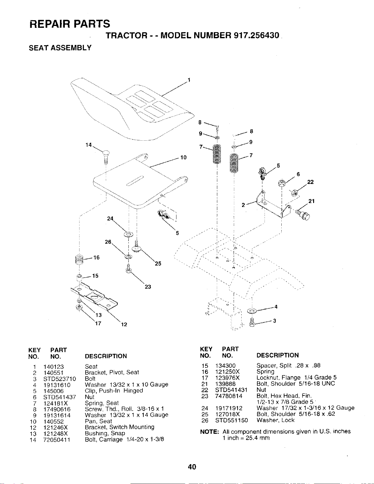
REPAIR PARTS
TRACTOR -- MODEL NUMBER 917.256430
SEAT ASSEMBLY
\
\\
\
&._j3
KEY
NO.
1
2
3
4
5
6
7
8
9
10
12
13
14
PART
NO.
140123
140551
STD523710
1913161O
145006
STD541437
124181X
17490616
19131614
140552
121246X
121248X
72050411
DESCRIPTION
Seat
Bracket, Pivot, Seat
Bolt
Washer !3/32 x 1 x 10 Gauge
Clip, Push-In Hinged
Nut
Spring, Seat
Screw, Thd., Roll. 3/8-16 x 1
Washer 13/32 x 1 x 14 Gauge
Pan, Seat
Bracket, Switch Mounting
Bushing, Snap
Bolt, Carriage 1/4-20 x 1-3/8
KEY PART
NO. NO. DESCRIPTION
15 134300
16 121250X
17 !23976X
21 139888
22 STD541431
23 74780814
24 19171912
25 127018X
26 STD551150
Spacer, Split .28 x.88
Spring
Locknut, Flange 1/4 Grade 5
Bolt, Shoulder 5/16-18 UNC
Nut
Bolt, Hex Head. Fin.
1/2-13 x 7/8 Grade 5
Washer 17/32 x 1-3/!6 x 12 Gauge
Bolt, Shoulder 5/16-18 x ,62
Washer. Lock
NOTE: All component dimensions given in U.S. inches
1 inch = 25.4 mm
40
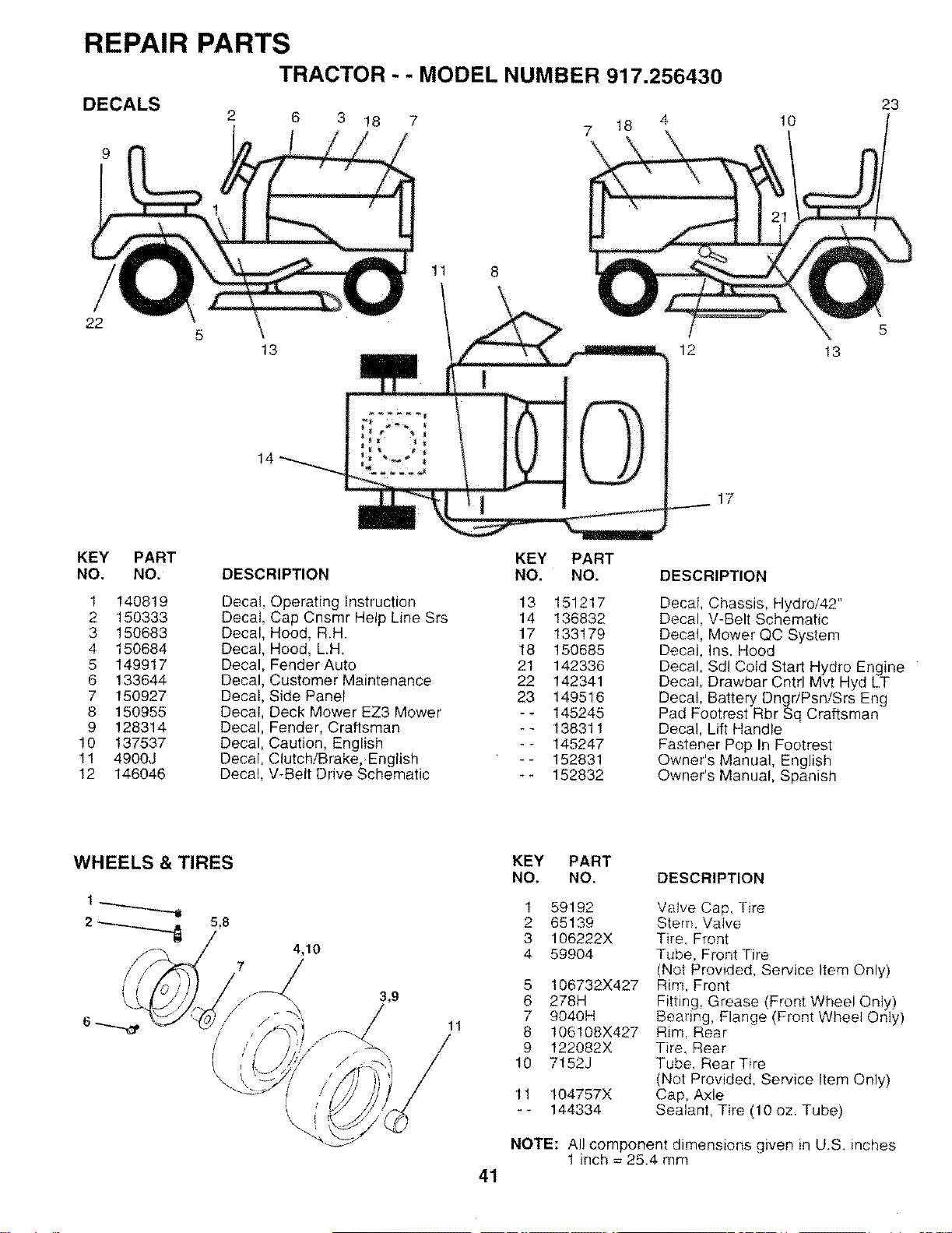
REPAIR PARTSTRACTOR - - MODEL NUMBER 917.256430
DECALS
9
22 5
2
13
14
3 18 7
11 8
7 18 10
5
12 13
17
23
KEY PART
NO. NO.
1 140819
2 150333
3 150683
4 150684
5 149917
6 133644
7 150927
8 150955
9 128314
10 137537
11 4900J
12 146046
DESCRIPTION
Decal, Operating Instruction
Cecal, Cap Cnsmr Help Line Srs
Decal, Hood, R.H.
Ceca!, Hood, LH.
Decal, Fender Auto
Decal, Customer Maintenance
Decal, Side Panel
Decal, Deck Mower EZ3 Mower
Decal, Fender, Craftsman
Decal, Caution, English
Decal, Clutch/Brake, English
Decal, V-Belt Drive Schematic
KEY PART
NO. NO.
13 151217
14 136832
17 133179
18 150685
21 142336
22 142341
23 149516
-- 145245
-- 138311
-- 145247
-- 152831
-- 152832
DESCRIPTION
Decal, Chassis, Hydro/42"
Decal, V-Belt Schematic
Decal, Mower QC System
Decal, Ins. Hood
Decal, Sdl Cold Start Hydro Engine
Decal, Drawbar Cntrl Mvt Hyd LT
Decal, Battery DngriPsn/Srs Eng
Pad Footrest Rbr Sq Craftsman
Decal, Lift Handle
Fastener Pop In Footrest
Owner's Manual, English
Owner's Manual, Spanish
WHEELS & TIRES
f
\\
4,10
3,9
J
11
KEY PART
NO. NO. DESCRIPTION
1
2
3
4
59192
65139
106222X
59904
5 106732X427
6 278H
7 9040H
8 106!08X427
9 122082X
10 7!52J
11 104757X
_- 144334
Valve Cap, Tire
Stem. Valve
Tire, Front
Tube, Front Tire
(Not Provided, Service Item Only)
Rim, Front
Fitting, Grease (Front Wheel Only)
Bearing, Flange (Front Wheel Only)
Rim, Rear
Tire, Rear
Tube, Rear Tire
(Not Provided, Service Item Only)
Cap, Axle
Sealant, Tire (10 oz. Tube)
NOTE: Al! component dimensions given in U.S. inches
1 inch = 25.4 mm
41
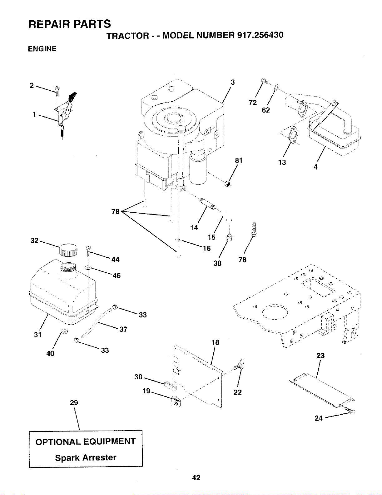
REPAIR PARTSTRACTOR -- MODEL NUMBER 917.256430
ENGINE
62
13
\
4
31 /
40 33
29
OPTIONAL EQUIPMENT
Spark Arrester L
38 78
Tf_L_ _ _
_ _ _ _ __ I<, _
\\
18
22
23
42
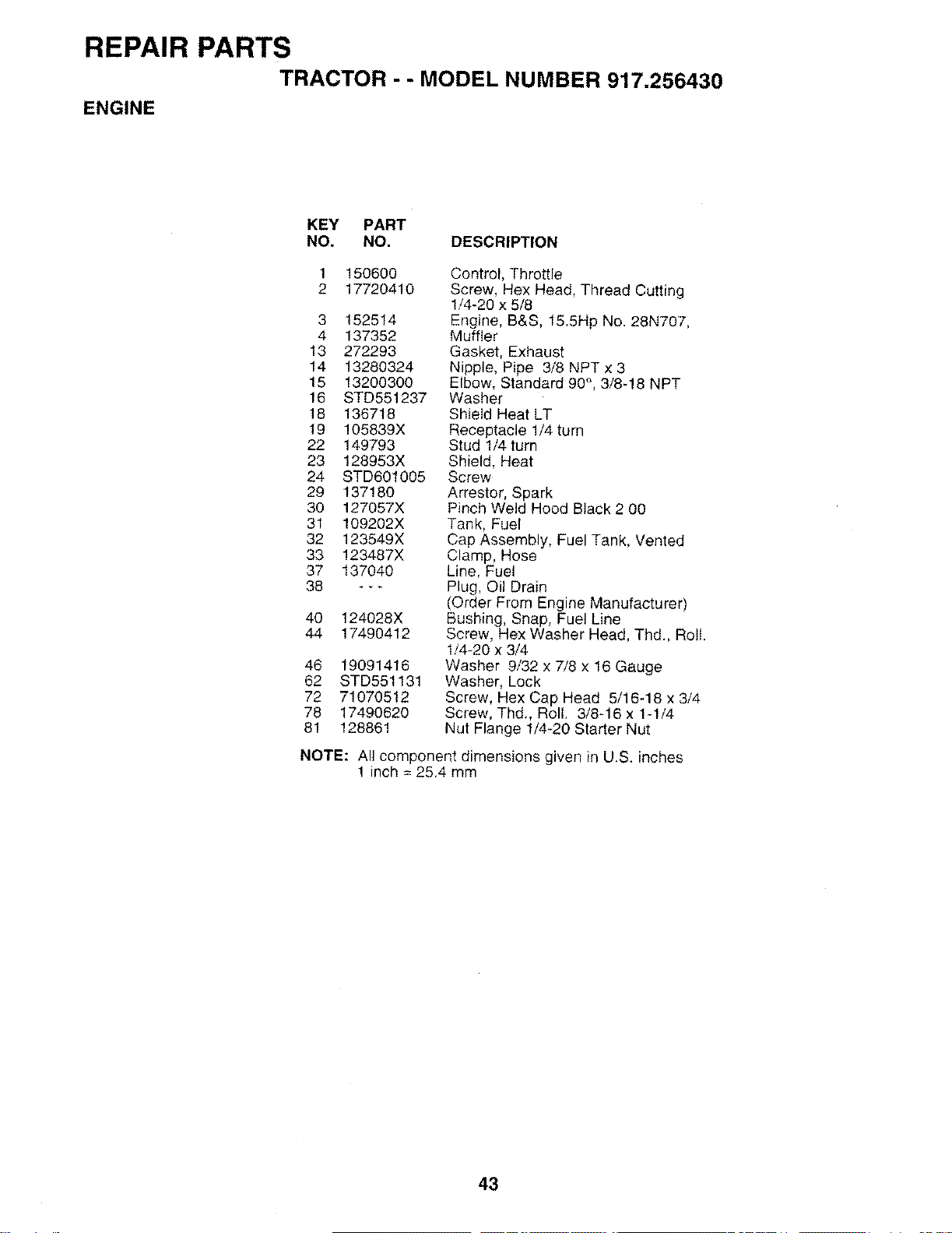
REPAIR PARTS
TRACTOR - - MODEL NUMBER 917.256430
ENGINE
KEY PART
NO. NO. DESCRIPTION
1 150600
2 17720410
3 152514
4 137352
13 272293
14 13280324
15 13200300
16 STD551237
18 136718
19 105839X
22 149793
23 128953X
24 STD601005
29 137180
30 127057X
31 109202X
32 123549X
33 123487X
37 137040
38 ---
40 124028X
44 17490412
46 19091416
62 STD551131
72 71070512
78 17490620
81 128861
Control, Throttle
Screw, Hex Head, Thread Cutting
1/4-20 x 5/8
Engine, B&S, 15.5Hp No. 28N707,
Muffler
Gasket, Exhaust
Nipple, Pipe 3/8 NPT x 3
Elbow, Standard 90°, 3/8-18 NPT
Washer
Shield Heat LT
Receptacle 1/4 turn
Stud 1/4 turn
Shield, Heat
Screw
Arrestor, Spark
Pinch Weld Hood Black 2 00
Tank, Fuel
Cap Assembly, Fuel Tank, Vented
Clamp, Hose
Line, Fuel
Plug, Oil Drain
(Order From Engine Manufacturer)
Bushing, Snap, Fuel Line
Screw, Hex Washer Head, Thd., Roll.
1/4-20 x 3/4
Washer 9/32 x 7/8 x 16 Gauge
Washer, Lock
Screw, Hex Cap Head 5/16-18 x 3/4
Screw, Thd., Roll. 3/8-16 x 1-1/4
Nut Flange 1/4-20 Starter Nut
NOTE: Al! component dimensions given in U.S. inches
1 inch = 25.4 mm
43
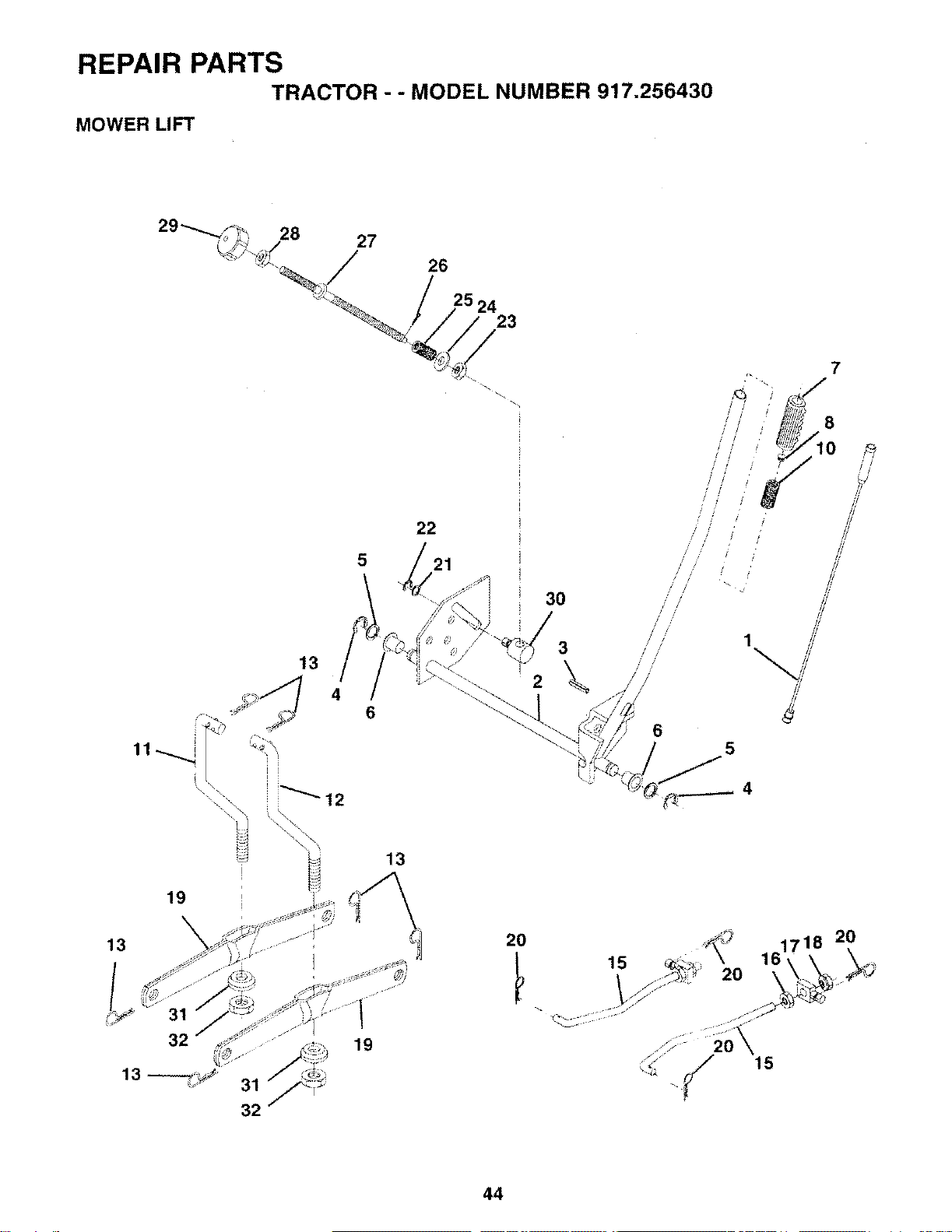
REPAIR PARTSTRACTOR - - MODEL NUMBER 917.256430
MOWER LIFT
28 27
26
23
22
5
46
13
19
30
3
2
19
1
/
i
!
i
//
/ !
/
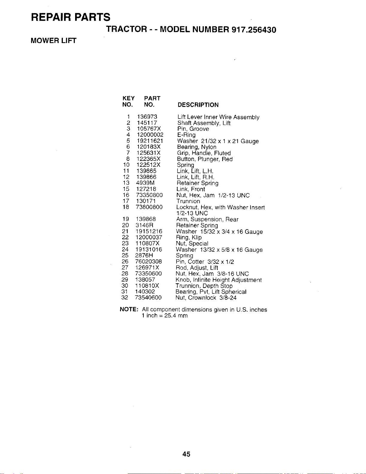
REPAIR PARTSTRACTOR - -MODEL NUMBER 917.256430
MOWER LIFT
KEY PART
NO. NO, DESCRIPTION
1 136973
2 145117
3 105767X
4 12000002
5 19211621
6 120183X
7 125631X
8 122365X
10 122512X
11 139865
12 139866
13 4939M
15 127218
16 73350800
17 130171
18 73800800
19 139868
20 3146R
21 19151216
22 12000037
23 110807X
24 19131016
25 2876H
26 76020308
27 126971X
28 73350600
29 138057
30 110810X
31 140302
32 73540600
Lift Lever Inner Wire Assembly
Shaft Assembly, Lift
Pin, Groove
E-Ring
Washer 21/32 x 1 x 21 Gauge
Bearing, Nylon
Grip, Handle, Fluted
Button, Plunger, Red
Spring
Link, Lift, LH.
Link, Lilt, R.H.
Retainer Spring
Link, Front
Nut, Hex, Jam 1/2-13 UNC
Trunnion
Locknut, Hex, with Washer Insert
1/2-13 UNC
Arm, Suspension, Rear
Retainer Spring
Washer 15/32 x 3/4 x 16 Gauge
Ring, Klip
Nut, Special
Washer 13/32 x 5/8 x 16 Gauge
Spring
Pin, Cotter 3/32 x 1/2
Rod, Adjust, Lift
Nut, Hex, Jam 3/8-16 UNC
Knob, Infinite Height Adjustment
Trunnion, Depth Stop
Bearing, Pvt, Lift Spherical
Nut, Crownlock 3/8-24
NOTE: All component dimensions given in U,S. inches
1 inch = 25.4 mm
45
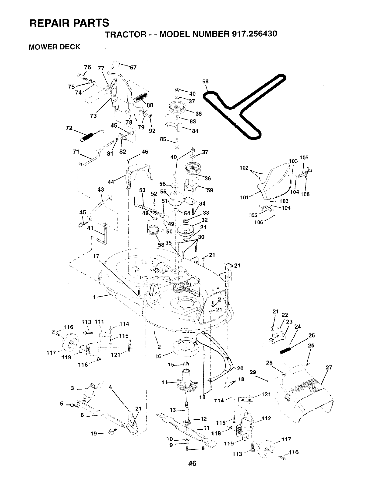
REPAIR PARTS
TRACTOR - - MODEL NUMBER 917.256430
MOWER DECK
76
73
79 92
68
I
102
18
105
106
<--103
105 j,-
106/_
21 22
/23 24
25
•26
27
46
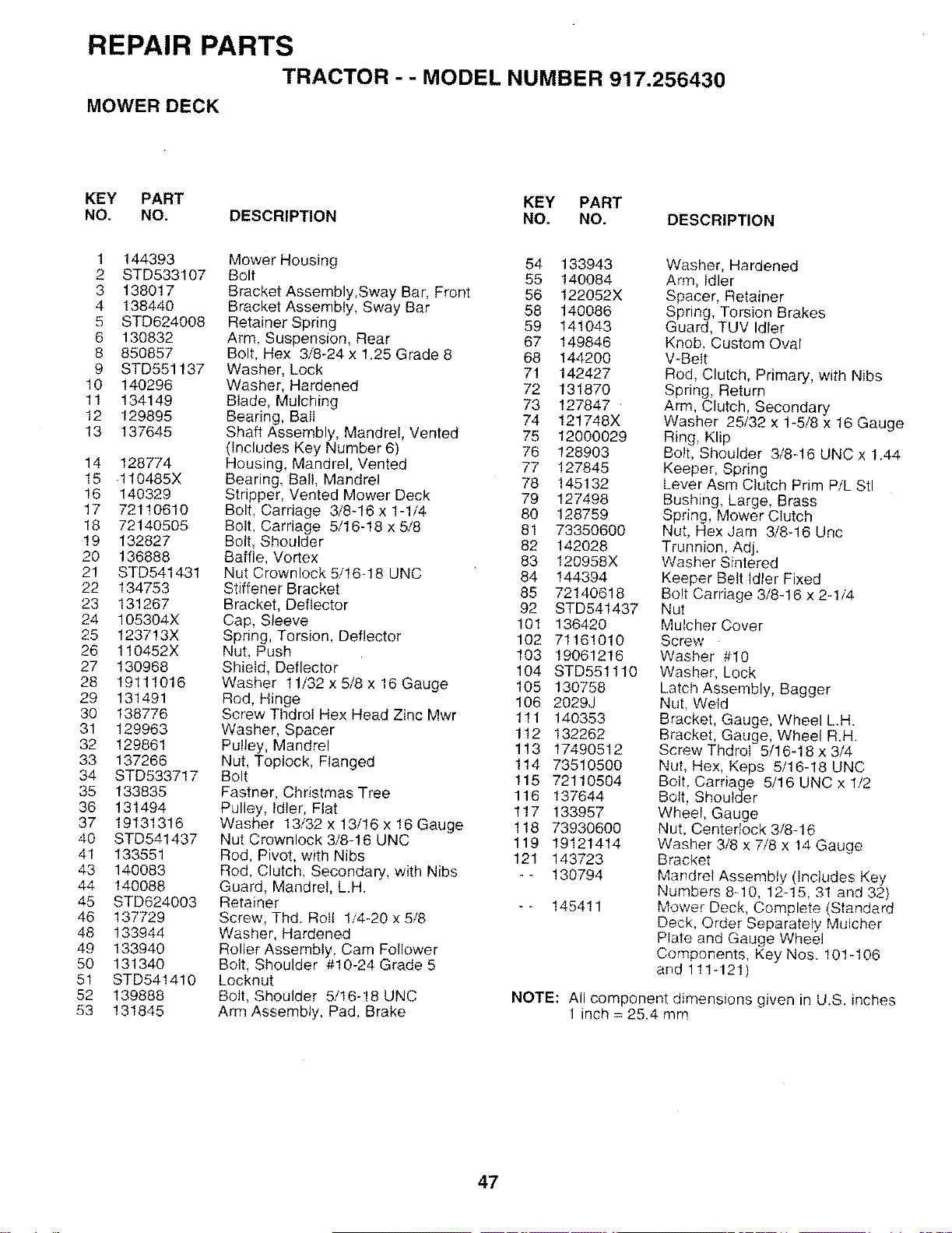
REPAIR PARTS
TRACTOR - - MODEL NUMBER 917.256430
MOWER DECK
KEY PART KEY PART
NO. NO. DESCRIPTION NO. NO. DESCRIPTION
1 144393
2 STD533107
3 138017
4 138440
5 STD624008
6 130832
8 850857
9 STD551137
10 140296
11 134149
12 129895
13 137645
14 128774
15 ,110485X
16 140329
17 72110610
18 72140505
19 132827
20 136888
21 STD541431
22 134753
23 131267
24 105304X
25 123713X
26 110452X
27 130968
28 19111016
29 131491
30 138776
31 129963
32 129861
33 137266
34 STD533717
35 133835
36 131494
37 19131316
40 STD541437
41 133551
43 140083
44 140088
45 STD624003
46 137729
48 133944
49 133940
50 131340
51 STD541410
52 139888
53 131845
Mower Housing 54 133943
Bolt 55 140084
Bracket Assembly,Sway Bar, Front 56 122052X
Bracket Assembly, Sway Bar 58 140086
Retainer Spring 59 141043
Arm. Suspension, Rear 67 149846
Bolt, Hex 3/8-24 x 1.25 Grade 8 68 144200
Washer, Lock 71 142427
Washer, Hardened 72 131870
Biade, Mulching 73 127847
Bearing, Bail 74 121748X
Shaft Assembly, Mandrel, Vented 75 12000029
(includes Key Number 6) 76 128903
Housing, Mandrel, Vented 77 127845
Bearing, Bali, Mandrel 78 145132
Stripper, Vented Mower Deck 79 127498
Bolt, Carriage 3/8-16 x !-1/4 80 128759
Bolt. Carriage 5/16-18 x 5/8 81 73350600
Bolt, Shoulder 82 142028
Baffle, Vor[ex 83 120958X
Nut Crownlock 5/!6-18 UNC 84 144394
Stiffener Bracket 85 72140618
Bracket, Deflector 92 STD541437
Cap, Sleeve 101 136420
Spring, Torsion, Deflector 102 71161010
Nut, Push 103 19061216
Shield, Deflector 104 STD551110
Washer 11/32 x 5/8 x 16 Gauge 105 130758
Rod. Hinge 106 2029J
Screw ThdroI Hex Head Zinc Mwr 111 140353
Washer, Spacer 1!2 132262
Pulley, Mandrel 1!3 17490512
Nut, Toplock, Flanged 114 73510500
Bolt 115 72110504
Fastner, Christmas Tree 116 137644
Pulley, Idler, Flat 117 133957
Washer 13/32 x !3/16 x 16 Gauge 118 73930600
Nut Crownlock 3/8-!6 UNC 119 19121414
Rod, Pivot, with Nibs 121 143723
Rod, Clutch, Secondary, with Nibs - - 130794
Guard, Mandrel, LH.
Retainer -- 145411
Screw, Thd. Roll 1.4-20 x 5/8
Washer, Hardened
Roller Assembly, Cam Follower
Bolt. Shoulder #10-24 Grade 5
Locknut
Bolt, Shoulder 5/16-18 UNC
Arm Assembly, Pad. Brake
Washer, Hardened
Arm, Idler
Spacer, Retainer
Spring, Torsion Brakes
Guard, TUV Idler
Knob, Custom Oval
WBelt
Rod, Clutch, Primary, with Nibs
Spring, Return
Arm, Clutch, Secondary
Washer 25/32 x 1-5/8 x 16 Gauge
Ring, Klip
Bolt, Shoulder 3/8q 6 UNC x 1.44
Keeper, Spring
Lever Asm Clutch Prim P/L Stl
Bushing, Large, Brass
Spring, Mower Clutch
Nut, Hex Jam 3/8-16 Uric
Trunnion, Adj.
Washer Sfntered
Keeper Belt Idler Fixed
Bolt Carriage 3/8-16 x 2-1/4
Nut
Muicher Cover
Screw
Washer #10
Washer, Lock
Latch Assembly, Bagger
Nut, Weld
Bracket, Gauge, Wheel LH.
Bracket, Gauge, Wheel R.H.
Screw ThdroI 5/16-18 x 3/4
Nut, Hex, Keps 5/16-18 UNC
Bolt, Carriage 5/16 UNC x 1/2
Bolt, Shoulder
Wheel, Gauge
Nut, Centerlock 3/8-16
Washer 3/8 x 7/8 x 14 Gauge
Bracket
Mandrel Assembly (includes Key
Numbers 8-10, 12-15, 31 and 32)
Mower Deck, Complete (Standard
Deck, Order Separately Mulcher
Plate and Gauge Wheel
Components, Key Nos. 101q06
and 111_121)
NOTE: All component dimensions given in U.S. inches
1 inch = 25.4 mm
47
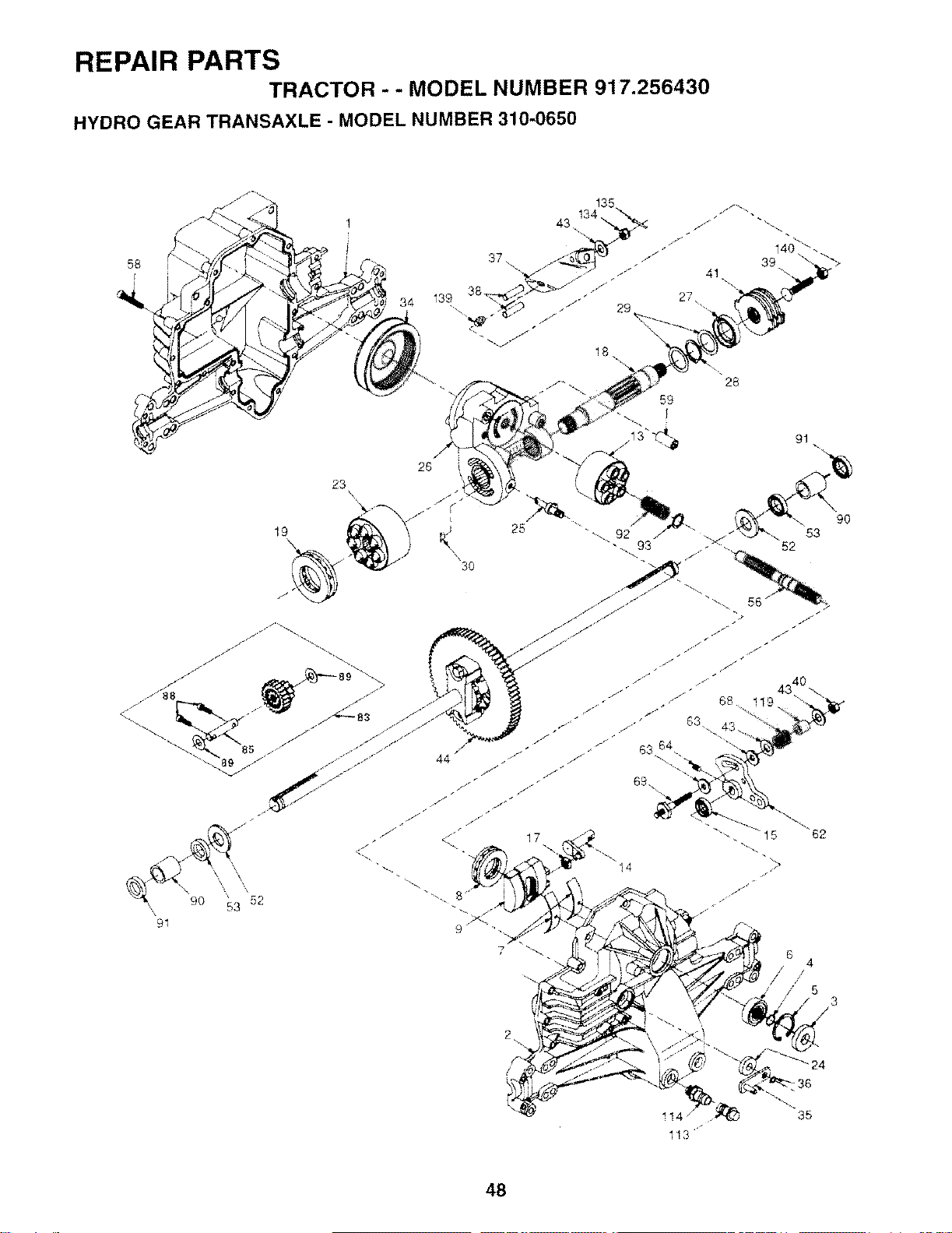
REPAIR PARTSTRACTOR - - MODEL NUMBER 917.256430
HYDRO GEAR TRANSAXLE - MODEL NUMBER 310-0650
58
23 \X
19
\
/
/
/ //'7t
// "
J_
91
34
26
53 9O
97
14
/6 /4
/53
/
-d35
113
48
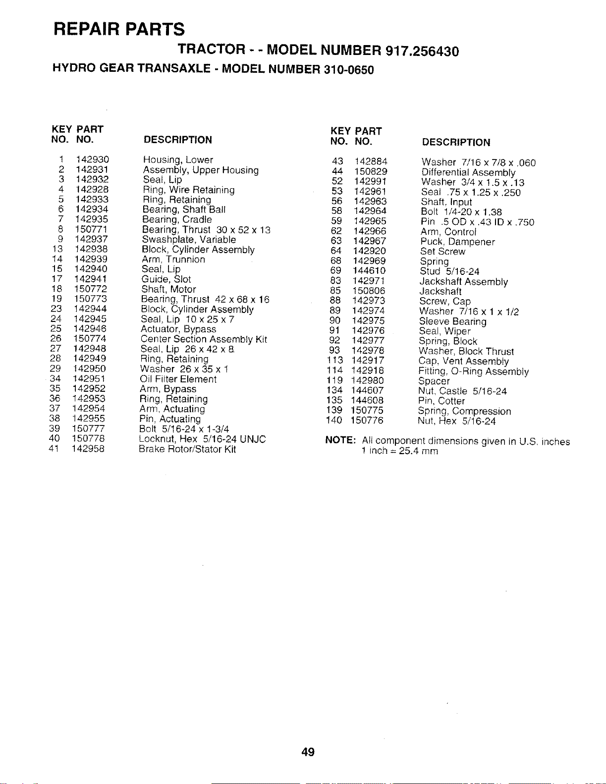
REPAIR PARTSTRACTOR - - MODEL NUMBER 917.256430
HYDRO GEAR TRANSAXLE -MODEL NUMBER 310-0650
KEY PART KEY PART
NO. NO. DESCRIPTION NO. NO. DESCRIPTION
1 142930 Housing, Lower 43 142884 Washer 7/!6 x 7/8 x .060
2 142931 Assembly, Upper Housing 44 150829 Differential Assembly
3 142932 Seat, Lip 52 142991 Washer 3/4x 1.5 x.13
4 142928 Ring, Wire Retaining 53 142961 Seal .75 x 1.25 x.250
5 142933 Ring, Retaining 56 142963 Shaft, Input
6 142934 Bearing, Shaft Ball 58 142964 Bolt 1/4-20 x 1.38
7 142935 Bearing, Cradle 59 142965 Pin .50D x.43 ID x.750
8 !5077! Bearing, Thrust 30 x 52 x 13 62 142966 Arm, Control
9 142937 Swashplate, Variable 63 142967 Puck. Dampener
13 142938 Block, Cylinder Assembly 64 142920 Set Screw
14 142939 Arm, Trunnion 68 142969 Spring
15 142940 Seal, Lip 69 144610 Stud 5/!6-24
17 142941 Guide, Slot 83 142971 Jackshaft Assembly
18 150772 Shaft, Motor 85 150806 Jackshaft
19 150773 Bearing, Thrust 42 x 68 x 16 88 142973 Screw, Cap
23 142944 Block, Cylinder Assembly 89 142974 Washer 7/16 x 1 x 1/2
24 142945 Seal, Lip t0 x 25 x 7 90 142975 Sleeve Bearing
25 142946 Actuator, Bypass 91 142976 Seal, Wiper
26 150774 Center Section Assembly Kit 92 142977 Spring, Block
27 142948 Seal, Lip 26 x 42 x 8 93 142978 Washer, Block Thrust
28 142949 Ring, Retaining !13 142917 Cap, Vent Assembly
29 142950 Washer 26 x 35 x 1 114 142918 Fitting, O-Ring Assembly
34 142951 Oil Filter Element 119 142980 Spacer
35 142952 Arm, Bypass 134 144607 Nut, Castie 5/16_24
36 142953 Ring, Retaining 135 144608 Pin, Cotter
37 142954 Arm, Actuating 139 150775 Spring, Compression
38 142955 Pin, Actuating 140 150776 Nut, Hex 5/16-24
39 150777 Bolt 5/16-24 x 1-3/4
40 150778 Locknut, Hex 5/16-24 UNJC NOTE: All component dimensions given in U.S. inches
41 142958 Brake RotoriStator Kit 1 inch = 25.4 mm
49
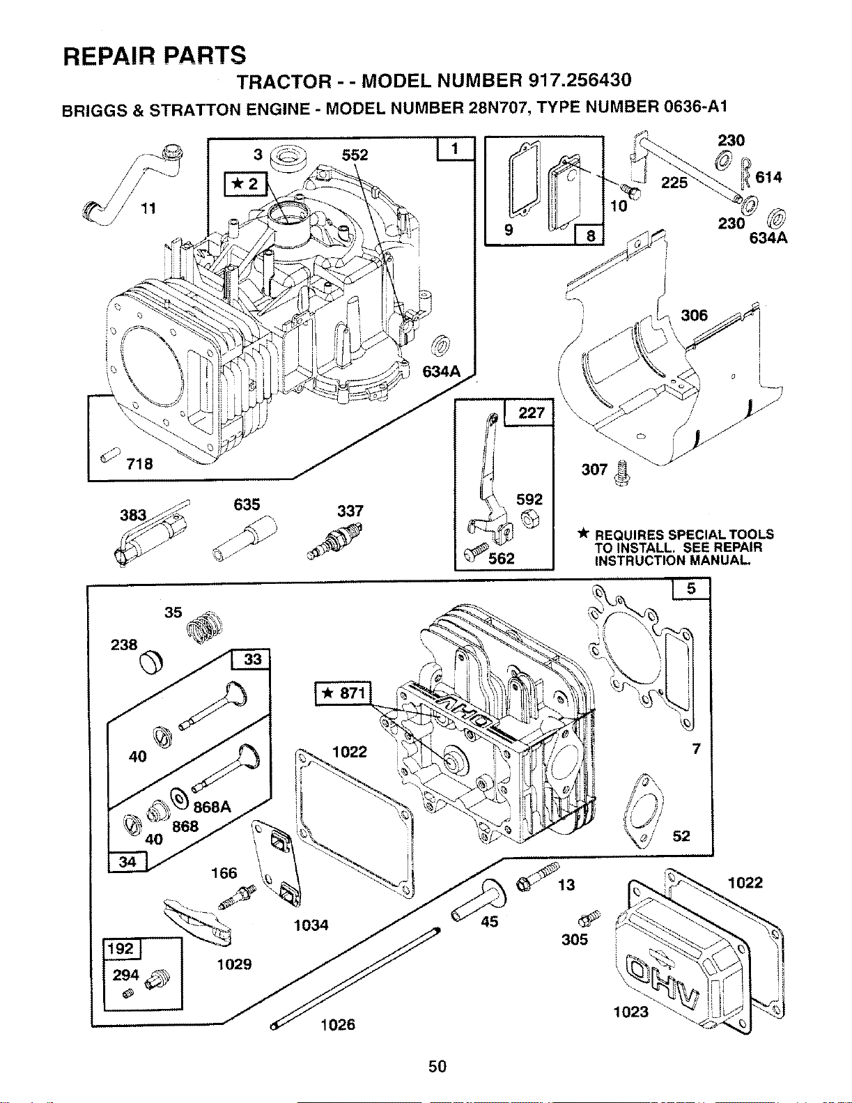
REPAIR PARTSTRACTOR - - MODEL NUMBER 917.256430
BRIGGS & STRATTON ENGINE - MODEL NUMBER 28N707, TYPE NUMBER 0636-A1
718
3
_'_ 635
_J 337
ss2 I1
634A
230
614
9 230 634A
_\ 592
REQUIRES SPECIAL TOOLS
TO INSTALL. SEE REPAIR
INSTRUCTION MANUAL
238 \
1022 7
52
294
1034
1029
1026
45 305
_1022
5O
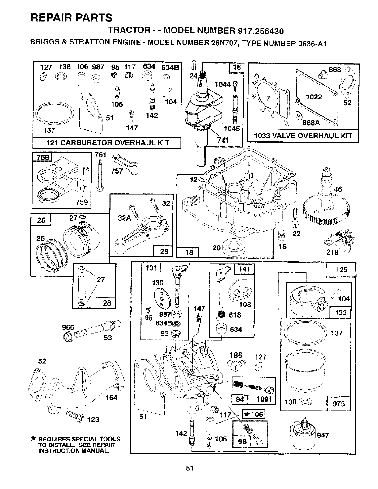
REPAIR PARTS
TRACTOR - - MODEL NUMBER 917.256430
BRIGGS & STRATTON ENGINE - MODEL NUMBER 28N707, TYPE NUMBER 0636-A1
127 138 106 987 95 117 634 634B
105 104
51 +142
147
121 CARBURETOR OVERHAUL KIT
759
52
REQUIRES SPECIAL TOOLS
TO INSTALL. SEE REPAIR
INSTRUCTION MANUAL.
757 \j
]i
@
32
_+ 741 ,
,8 2o(_ /,5
130
634B_
93@
1044
1045
\1033 VALVE OVERHAUL KIT j
142
•46
U108
186 127
j,
][ 125
i
137
138 _
947
51
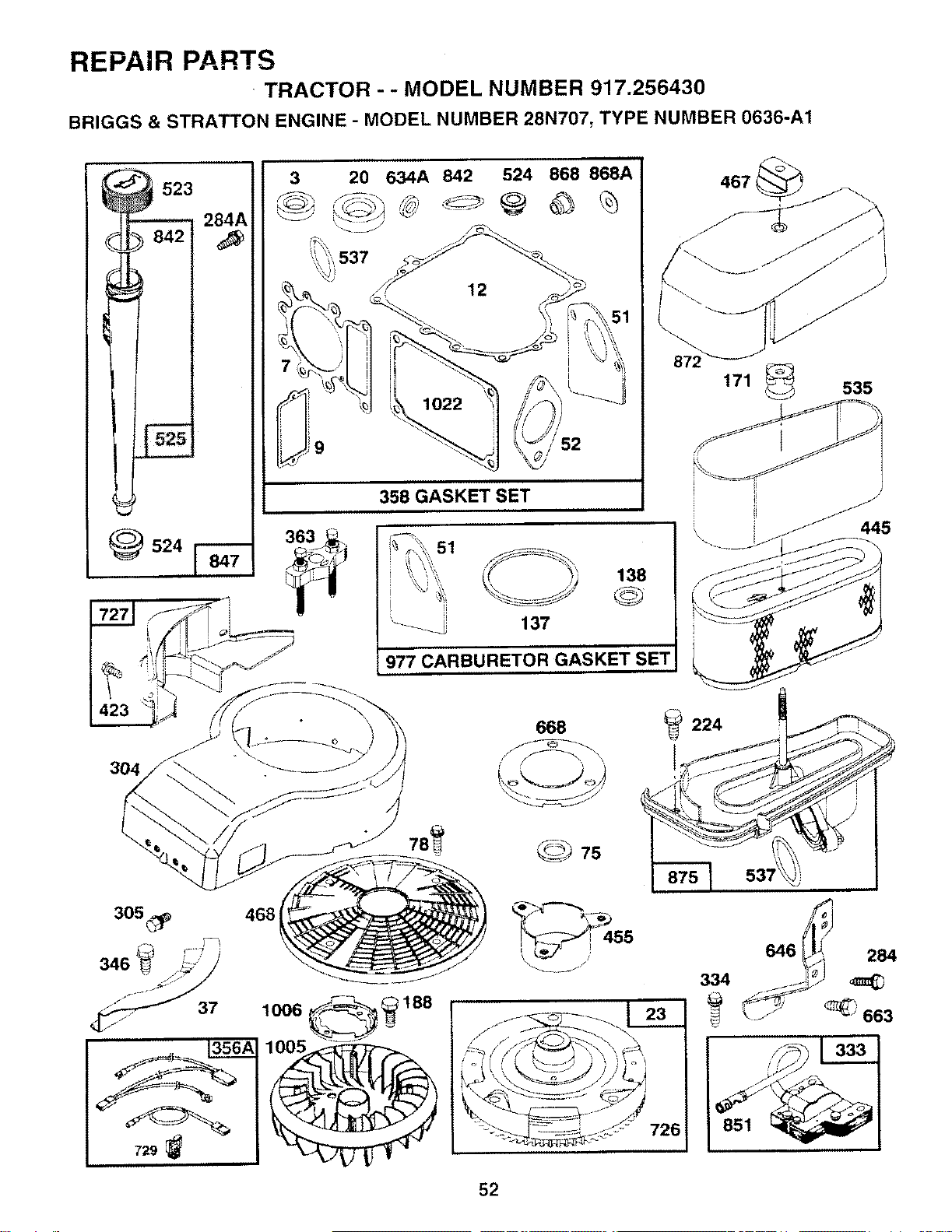
REPAIR PARTS
TRACTOR - -MODEL NUMBER 917.256430
BRIGGS & STRATTON ENGINE - MODEL NUMBER 28N707, TYPE NUMBER 0636-A1
284A
842
_524
ii
9
20 634A 842 524 868 868A
,537 ___
m i
358 GASKET SET
3632 51
_137
138
977 CARBURETOR GASKET SET
467
171 _535
_5
729
668
_7s
_224
53;
334
646 284
J _ 66z
52
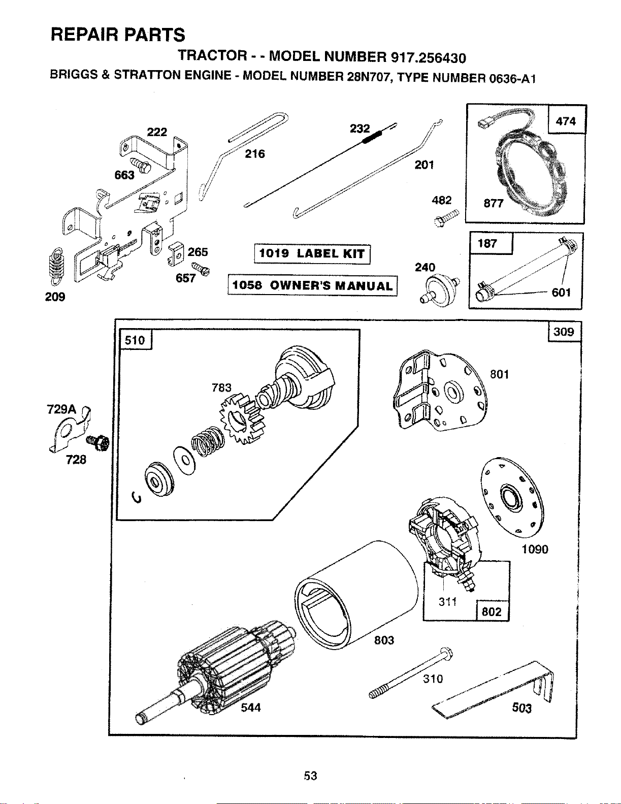
REPAIR PARTS
TRACTOR --MODEL NUMBER 917.256430
BRIGGS & STRATTON ENGINE -MODEL NUMBER 28N707, TYPE NUMBER 0636-A1
_222
209
201
482
,S
1019 LABEL KITI 240
11058 OWNER'S MANUAL!
877
729A
728
783
544
801
311
1090
t
53
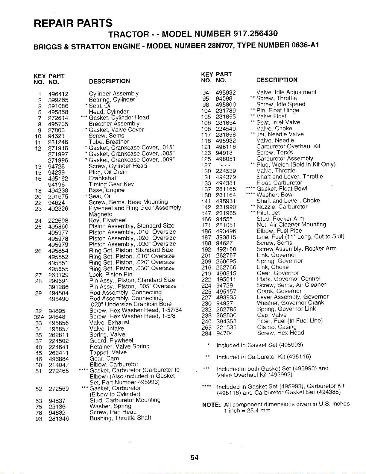
REPAIR PARTSTRACTOR - -MODEL NUMBER 917.256430
BRIGGS & STRATTON ENGINE -MODEL NUMBER 28N707, TYPE NUMBER 0636-A1
KEY PART KEY PART
NO, NO. DESCRIPTION NO. NO, DESCRIPTION
1 496412
2 399265
3 391086
5 495858
7 272614
8 495735
9 27803
10 94621
11 281246
12 271916
271997
271996
13 94728
15 94239
16 495162
94196
18 494238
20 291675
22 94624
23 492326
24 222698
25 495860
495977
495978
495979
26 495854
495852
495851
495855
27 263129
28 299691
391286
29 494504
495490
32 94695
32A 94648
33 495856
34 495857
35 262811
37 224502
40 224641
45 262411
46 496884
50 214047
51 272465
52 272569
53 94637
75 25136
78 94832
93 281346
Cylinder Assembly 94 495932
Bearing, Cylinder 95 94098
* Seal, Oil 98 495800
Head, Cylinder 104 231789
*** Gasket. Cylinder Head 105 231855
Breather Assembly 106 231854
*Gasket, Valve Cover 108 224540
Screw, Sems !17 231858
Tube, Breather 118 495932
* Gasket, Crankcase Cover, .015" 121 498116
* Gasket, Crankcase Cover, .005" 123 94913
*Gasket, CrankcaseCover, .009" 125 498051
Screw, Cylinder Head 127 - - -
Plug, Oil Drain 130 224539
Crankshaft 131 494379
Timing Gear Key 133 494381
Base, Engine 137 281165
*Seal, Oil 138 281164
Screw, Seres, Base Mounting 141 495931
Flywheel and Ring Gear Assembly, 142 231990
Magneto 147 231985
Key, Flywheel 166 94555
Piston Assembly, Standard Size 171 281051
Piston Assembly, .010" Oversize 186 493496
Piston Assembly, .020" Oversize 187 393815
Piston Assembly, .030" Oversize 188 94627
Ring Set, Piston, Standard Size 192 492160
Ring Set, Piston, .010" Oversize 201 262767
Ring Set, Piston, .020" Oversize 209 260695
Ring Set, Piston, .030" Oversize 216 262766
Lock, Piston Pin 219 490815
Pin Assy. Piston, Standard Size 222 495611
Pin Assy., Piston, .005" Oversize 224 94729
Rod Assembly, Connecting 225 495157
Rod Assembly, Connecting, 227 493935
.020" Undersize Crankpin Bore 230 94927
Screw, Hex Washer Head, 1-57/64 232 262785
Screw, Hex Washer Head, 1-5/8 238 262836
Valve, Exhaust 240 394358
Valve, Intake 265 221535
Spring, Valve 284 94704
Guard, Flywheel
Retainer, Valve Spring
Tappet, Valve
Gear, Cam
Elbow, Carburetor
.... Gasket, Carburetor (Carburetor to
Elbow) (Also Included in Gasket
Set, Part Number 495993)
*** Gasket, Carburetor
(Elbow to Cylinder)
Stud, Carburetor Mounting
Washer, Spring
Screw, Pan Head
Bushing, Throttle Shaft
Valve, Idle Adjustment
** Screw, Throttle
Screw, Idle Speed
"* Pin, Float Hinge
"* Vatve Float
_*Seat, Inlet Valve
Valve, Choke
** Jet, Needle Valve
Valve, Needle
Carburetor Overhaul Kit
Screw, Torx®
Carburetor Assembly
** Plug, Welch (Sold in Kit Only)
Valve, Throttle
Shaft and Lever, Throttle
Float. Carburetor
.... Gasket, Float Bowl
.... Washer, Bowl
Shaft and Lever, Choke
** Nozzle. Carburetor
*" Pilot, Jet
Stud, Rocker Arm
Nut. Air Cleaner Mounting
Elbow, Fuel Pipe
Line, Fuel (11" Long, Cut to Suit)
Screw, Sems
Screw Assembly, Rocker Arm
Link, Governor
_pring, Governor
Unk, Choke
Gear, Governor
Plate. Governor Control
Screw, Sems, Air Cleaner
Crank, Governor
Lever Assembly, Governor
Washer, Governor Crank
Spring, Governor Link
Cap, Valve
Filter, Fuel (In FueI Line)
Clamp, Casing
Screw, Hex Head
Included in Gasket Set (495993)
** Included in Carburetor Kit (4981!6)
*" Included in both Gasket Set (495993) and
Valve Overhaul Kit (495992)
.... Included in Gasket Set (495993), Carburetor Kit
(498116) and Carburetor Gasket Set (494385)
NOTE: All component dimensions given in U.S. inches
1 inch = 25.4 mm
54
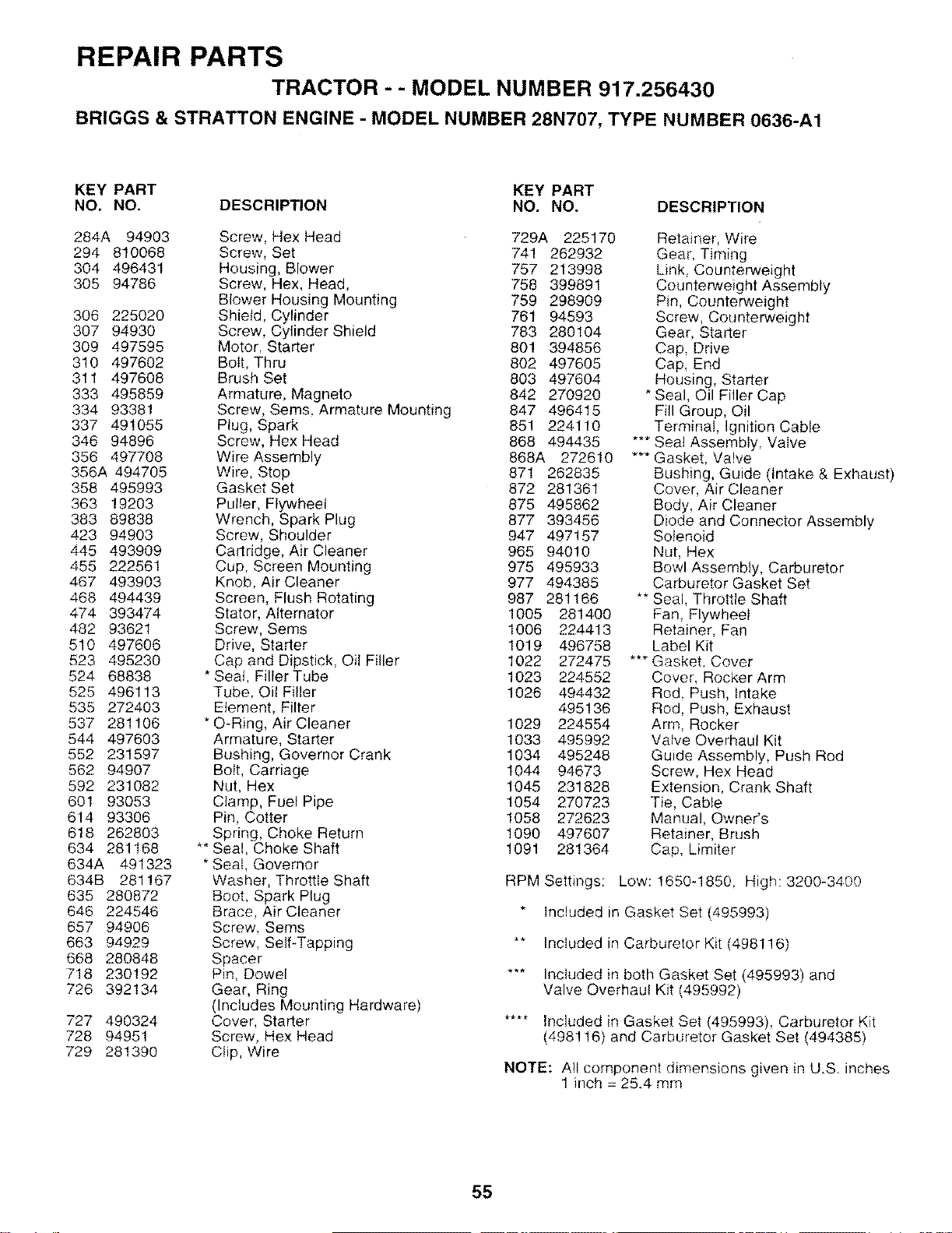
REPAIR PARTSTRACTOR - - MODEL NUMBER 917.256430
BRIGGS & STRATTON ENGINE - MODEL NUMBER 28N707, TYPE NUMBER 0636-A1
KEY PART KEY PART
NO. NO. DESCRIPTION NO. NO.
284A 94903 Screw, Hex Head 729A 225170
294 810068 Screw, Set 741 262932
304 496431 Housing, Blower 757 213998
305 94786 Screw, Hex, Head, 758 399891
Blower Housing Mounting 759 298909
306 225020 Shield, Cylinder 761 94593
307 94930 Screw, Cylinder Shield 783 280104
309 497595 Motor, Starter 801 394856
310 497602 Bolt, Thru 802 497605
311 497608 Brush Set 803 497604
333 495859 Armature, Magneto 842 270920
334 93381 Screw, Sems, Armature Mounting 847 496415
337 491055 Plug, Spark 851 224110
346 94896 Screw, Hex Head 868 494435
356 497708 Wire Assembly 868A 272610
356A 494705 Wire, Stop 871 262835
358 495993 Gasket Set 872 281361
363 19203 Puller, Flywheel 875 495862
383 89838 Wrench, Spark Plug 877 393456
423 94903 Screw, Shoulder 947 497157
445 493909 Cartridge, Air Cleaner 965 94010
455 222561 Cup, Screen Mounting 975 495933
467 493903 Knob, Air Cleaner 977 494385
468 494439 Screen, Flush Rotating 987 281166
474 393474 Stator, Alternator 1005 281400
482 93621 Screw, Sems 1006 224413
510 497606 Drive, Starter 1019 496758
523 495230 Cap and Dipstick, Oil Filler 1022 272475
524 68838 * Seat, FillerTube 1023 224552
525 496113 Tube, Oil Filler 1026 494432
535 272403 Element, Filter 495136
537 281106 * O-Ring, Air Cleaner 1029 224554
544 497603 Armature, Starter 1033 495992
552 231597 Bushing, Governor Crank 1034 495248
562 94907 Bolt, Carriage 1044 94673
592 231082 Nut, Hex 1045 231828
601 93053 Clamp, Fuel Pipe 1054 270723
614 93306 Pin, Cotter 1058 272623
618 262803 Spring, Choke Return 1090 497607
634 281168 ** Seal, Choke Shaft 1091 281364
634A 491323 * SeaI, Governor
634B 281167 Washer, Throttle Shaft
635 280872 Boot. Spark Plug
646 224546 Brace, Air Cleaner
657 94906 Screw. Seres
663 94929 Screw, Self-Tapping
668 280848 Spacer
718 230192 Pin, Dowel
726 392134 Gear, Ring
(Includes Mounting Hardware)
727 490324 Cover, Starter
728 94951 Screw, Hex Head
729 281390 Clip, Wire
DESCRIPTION
Retainer, Wire
Gear, Timing
Link, Counterweight
Counterweight Assembly
Pin, Counterweight
Screw, Counterweight
Gear, Starter
Cap, Drive
Cap, End
Housing, Starter
*Seal, Oil Filler Cap
Fill Group, Oi!
Terminal, Ignition Cable
*** Seat Assembly, Valve
*** Gasket, Valve
Bushing, Guide (Intake & Exhaust)
Cover, Air Cleaner
Body, Air Cleaner
Diode and Connector Assembly
Solenoid
Nut, Hex
Bowl Assembly, Carburetor
Carburetor Gasket Set
** Seal, Throttle Shaft
Fan, FlywheeI
Retainer, Fan
Label Kit
*** Gasket. Cover
Cover, Rocker Arm
Rod. Push, Intake
Rod, Push, Exhaust
Arm, Rocker
Valve Overhaul Kit
Guide Assembly, Push Rod
Screw, Hex Head
Extension, Crank Shaft
Tie, Cable
Manual, Owner's
Retainer, Brush
Cap, Limiter
RPM Settings: Low: !650-1850, High: 3200-3400
Included in Gasket Set (495993)
** Included in Carburetor Kit (498116)
*** Included in both Gasket Set (495993) and
Valve Overhaul Kit (495992)
.... Included in Gasket Set (495993), Carburetor Kit
(498!16) and Carburetor Gasket Set (494385)
NOTE: All component dimensions given in U.S. inches
1 inch = 25.4 mm
55

i
SERVICE NOTES
56

ii i
SERVICE NOTES
57

i ii i i_ ii
SERVICE NOTES
58

SUGGESTED GUIDE FOR SIGHTING SLOPES FOR SAFE OPERATION
SIGHTING
GUIDE
ONLY RIDE UP AND DOWN HILL,
NOT ACROSS HILL
SIGHT AND HOLD THIS LEVEL WITH
SKY LINE OR TREE.
t
15° MAX.
i, rj i
Operate your Tractor up and down the face of slopes (not !
greater than !5_), nevet" across the face, Make turns gradu_ I
al{y to prevent tipping or loss of control, Exercise extreme I
caution when changing direction on slopes.
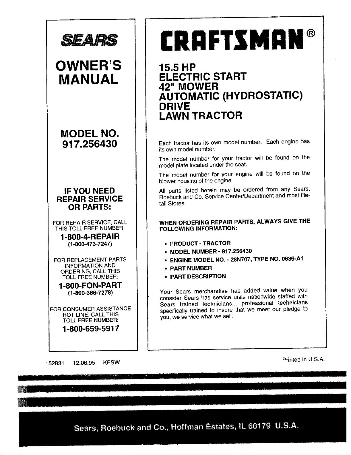
OWNER'S
MANUAL
MODEL NO.
917.256430
IF YOU NEED
REPAIR SERVICE
OR PARTS:
FOR REPAIR SERVICE, CALL
THIS TOLL FREE NUMBER:
1-800-4-REPAIR
(1-800-473-7247)
FOR REPLACEMENT PARTS
INFORMATION AND
ORDERING, CALL THIS
TOLL FREE NUMBER:
1-800-FON-PART
(1-800-366-7278)
"OR CONSUMER ASSISTANCE
HOT LINE, CALL THIS
TOLL FREE NUMBER:
1-800-659-5917
15.5 HP
ELECTRIC START
42" MOWER
AUTOMATIC (HYDROSTATIC)
DRIVE
LAWN TRACTOR
Each tractor has its own model number. Each engine has
its own model number.
The model number for your tractor will be found on the
model plate located under the seat.
The model number for your engine will be found on the
blower housing of the engine.
All parts listed herein may be ordered from any Sears,
Roebuck and Co. Service Center!Department and most Re-
tall Stores.
WHEN ORDERING REPAIR PARTS, ALWAYS GIVE THE
FOLLOWING INFORMATION:
• PRODUCT - TRACTOR
*MODEL NUMBER -917.256430
•ENGINE MODEL NO. -28N707, TYPE NO, 0636-A1
• PART NUMBER
* PART DESCRIPTION
Your Sears merchandise .has added value when you
consider Sears has service units nationwide staffed with
Sears trained technicians.., professional technicians
specifically trained to insure that we meet our pledge to
you, we service what we sell.
152831 12.06.95 KFSW Pdnted in U.S.A.
..................... _ I I IIII IIIHIIIIIIIIIIIIIIIIIIIIIIIIIIIIIIIIL
Nil ..... ii i ..........


