Page 1
240-3710
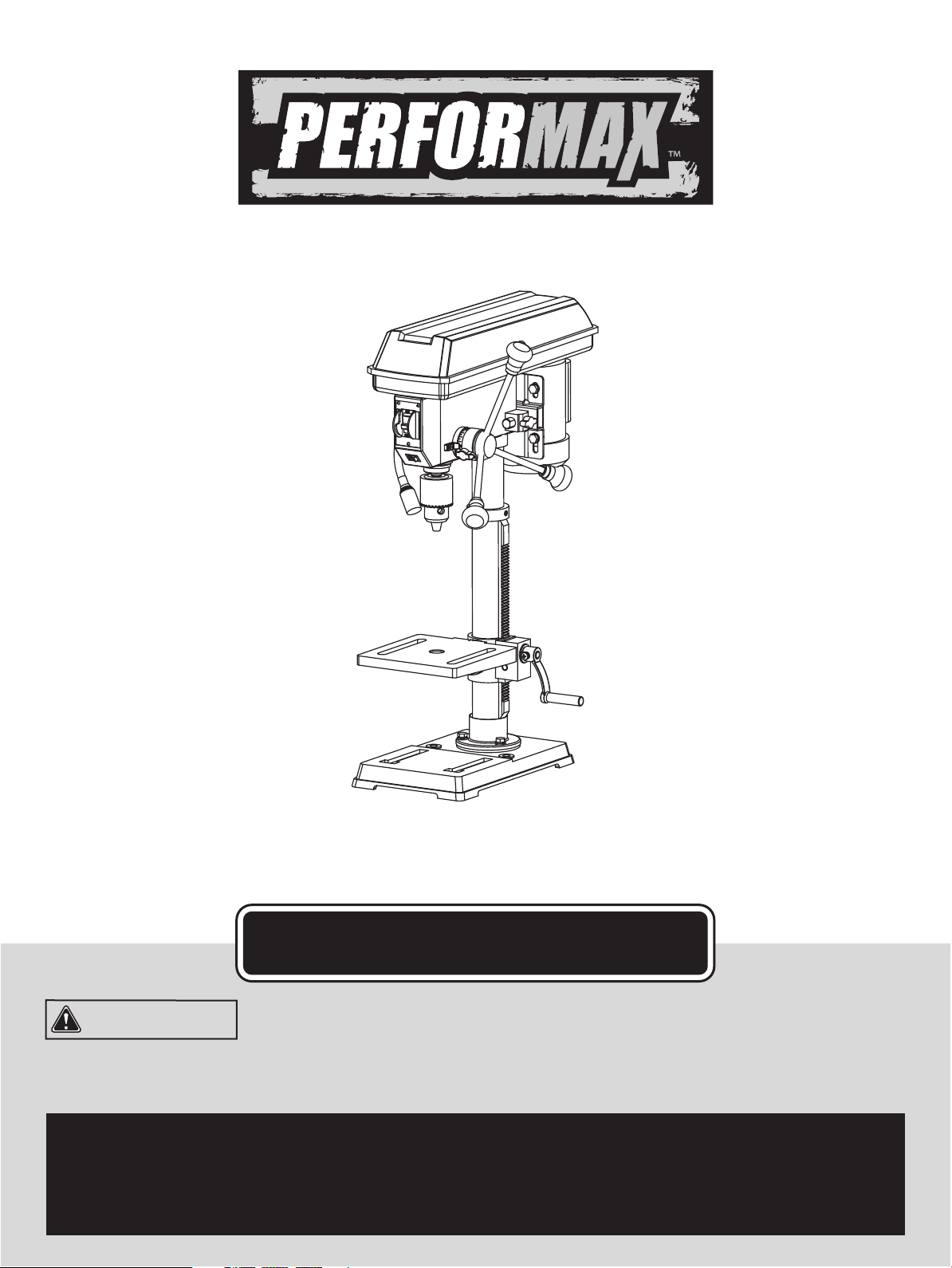
10" Drill Press with Laser
OPERATOR’S MANUAL
CAUTION: To Reduce The Risk Of Injury, User Must Read
And Understand Operator’s Manual. Save These Instructions
For Future Reference.
For questions / comments, technical assistance or repair
parts - Please call toll free at: 1-877-684-8912 (Monday -
Friday 8am - 6pm EST.)

TABLE OF CONTENTS
Safety Symbols ............................................................................................................................................................
Safety Instructions .......................................................................................................................................................
Overview ....................................................................................................................................................................
Specications ............................................................................................................................................................
Contents ....................................................................................................................................................................
Assembly ...................................................................................................................................................................
Adjustments ...............................................................................................................................................................
Operation ...................................................................................................................................................................
Maintenance ..............................................................................................................................................................
Troubleshooting .........................................................................................................................................................
Replacement parts list ...............................................................................................................................................
Warranty......................................................................................................................................................................
Page 2
Page 3
Page 10
Page 11
Page 12
Page 13
Page 17
Page 21
Page 26
Page 27
Page 28
Page 29
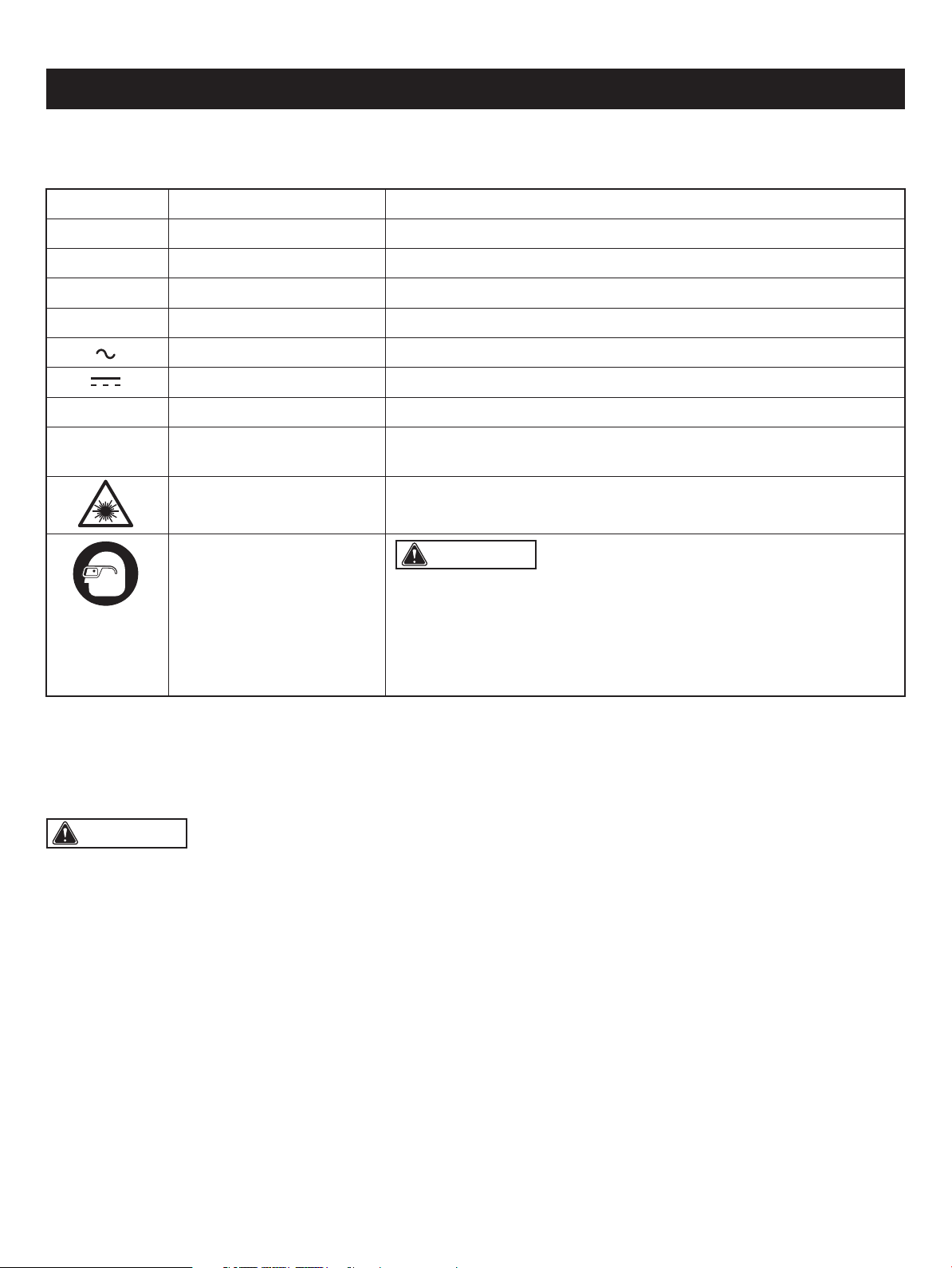
Some of these following symbols may be used on this tool. Please study them and learn their meaning. Proper interpretation
of these symbols will allow you to operate the tool better and safer.
SAFETY SYMBOLS
Page 2
WARNING: The operation of any power tool can result in
foreign objects being thrown into your eyes, which can result in severe
eye damage. Before beginning power tool operation, always wear
safety goggles or safety glasses with side shields and a full-face shield
when needed. We recommend a Wide Vision Safety Mask for use over
eyeglasses or standard safety glasses with side shields. Always use
eye protection which is marked to comply with ANSI Z87.1.
Symbol Name Designation / Explanation
V Volts Voltage
A Amperes Current
Hz Hertz Frequency (cycles per second)
W Watts Power
Alternating current Type of current
Direct current Type of characteristic of current
no No-load speed Rotational speed at no load
.../min
Per minute Revolutions, strokes, surface speed orbits, etc., per minute
Wear safety goggles
Laser radiation Do not stare into beam or view directly with optical instruments
WARNING: To ensure safety and reliability, all repairs should be performed by a qualied service technician.

The purpose of safety symbols is to attract your attention to possible dangers. The safety symbols and the explanations
with them deserve your careful attention and understanding. The symbol warnings do not, by themselves, eliminate any
danger. The instructions and warnings they give are no substitutes for proper accident prevention measures.
SAFETY INSTRUCTIONS
Page 3
WARNING: Be sure to read and understand all safety instructions in this manual, including all safety alert symbols
such as “DANGER,” “WARNING,” and “CAUTION” before using this tool. Failure to follow all instructions listed below may
result in electric shock, re, and/or serious personal injury.
WARNING: Indicates a potentially hazardous situation, which, if not avoided, could result in death
or serious injury.
CAUTION: Indicates a potentially hazardous situation, which, if not avoided, could result in minor or moderate
injury.
DANGER: Indicates an imminently hazardous situation, which, if not avoided, will result in death or serious injury.
SYMBOL MEANING
SAFETY ALERT SYMBOL: Indicates DANGER, WARNING, OR CAUTION. May be used in conjunction with
other symbols or pictographs.
NOTICE: (Without Safety Alert Symbol) Indicates a situation that may result in property damage.
SAVE THESE INSTRUCTIONS!

Safety is a combination of using common sense, staying
alert, and knowing how your drill press works. Read this
manual to understand this drill press and how to use
it safely.
GENERAL SAFETY IMFORMATION
SPECIFIC SAFETY RULES
GENERAL SAFETY RULES
WORK AREA
• Keep children away. Do not let visitors contact tool or
extension cord. All visitors should be kept at a safe distance
from work area.
• Keep work areas clean. Cluttered areas and benches
invite accidents.
• Make workshop childproof. With padlocks, master
switches, or by removing starter keys.
• Avoid dangerous environments. Don’t use power tools
in damp or wet locations. Keep work area well lit. Do not
expose power tools to rain. Do not use the tool in
the presence of ammable liquids or gases.
PERSONAL SAFETY
• Know your power tool. Read and understand the owner’s
manual and labels afxed to the tool. Learn the tool's uses
and limitations as well as the specic potential hazards
particular to this tool.
• Don’t overreach. Keep proper footing and balance at all
times.
• Stay alert. Watch what you are doing. Use common sense.
Do not operate tool when you are tired. Do not operate
while taking medication or while using alcohol or other
drugs.
• Wear proper apparel. Do not wear lose clothing, gloves,
neckties, rings, bracelets or other jewelry that may get
caught in moving parts. Nonslip footwear is recommended.
Wear protective hair covering to contain long hair.
• Always use safety glasses. Also use face or dust mask
if cutting operation is dusty, and ear plugs during extended
periods of operation. Everyday eyeglasses have only
impact-resistant lenses, they are NOT safety glasses.
• Guard against electric shock. Prevent body contact with
grounded surfaces. For example: pipes, radiators, ranges,
refrigerator enclosures.
• Disconnect tools from power source, when not in use,
before servicing, when changing blades, bits, cutters, etc.
• Keep guards in place, in working order, and in proper
adjustment and alignment.
• Remove adjusting keys and wrenches when not in use,
before servicing and when changing blades, bits, cutters,
etc.
• Reduce the risk of unintentional starting. Make sure the
switch is in the “Off” position before plugging in the tool.
• Ground all tools. This tool is equipped with an approved
three conductor cord and a three prong grounding-type
plug to t the proper grounding-type receptacle. The green
conductor in the cord is the grounding wire. Never connect
the green wire to a live terminal.
• Never stand on tool or its stand. Serious injury could
occur if the tool is tipped or if the cutting tool is accidentally
contacted. Do not store materials on or near the tool such
that it is necessary to stand on the tool or its stand
to reach them.
• Check damaged parts. Before further use of the tool, a
guard or other part that is damaged should be carefully
checked to ensure that it will operate properly and perform
its intended function. Check for alignment of moving parts,
mounting and any other conditions that may affect the
tool's operation. A guard or other part that is damaged
should be properly replaced.
SAFETY INSTRUCTIONS
TOOL USE
• Don’t force tool. It will do the job better and safer at the
rate for which it was designed.
Page 4
WARNING: Read and understand all instructions.
Failure to follow all instructions listed below, may result in
electric shock, re and/or serious personal injury. Save all
warnings and instructions for future reference.
WARNING: For your own safety, do not try to use
your drill press or plug it in until it is completely assembled
and installed according to the instructions, and until you
have read and understood this instruction manual.
WARNING:
• All repairs, electrical or mechanical, should be attempted
only by trained technicians.
• Use only identical replacement parts. Any others may
create a hazard.
• The use of any other accessories may create a hazard.
WARNING: To avoid the risk of personal injury,
do not modify this power tool or use accessories not
recommended to t your tool.
CAUTION: Always follow proper operating
procedures as dened in this manual — even if you
are familiar with use of this or similar tools. Remember that
being careless for even a fraction of a second can result in
severe personal injury.

• Use the right tool. Don’t force a small tool or attachment
to do the job of a heavy-duty tool. Don’t use tool
for purpose not intended—for example, don’t use a circular
saw for cutting tree limbs or logs.
• Secure work. Use clamps or vise to hold work. It is safer
than using your hand and it frees both hands to operate
the tool.
• Keep bits clean and sharp. Sharp bits minimize stalling.
Dirty and dull bits may cause misalignment of the material
and possible operator injury.
• Be sure drill bit or cutting tool is securely locked in the
chuck.
• Be sure chuck key is removed from the chuck before
connecting to power source or turning power ON.
• Adjust the table or depth stop to avoid drilling into the
table. Shut off the power, remove the drill bit, and clean
the table before leaving machine.
• Never perform any operation by moving the head or
table with respect to one another. Do not turn the switch
ON or start any operation before checking that the head
and table support lock handle is clamped tight to column
and head and table support collars are correctly positioned.
• Never leave tool running unattended. Turn power off.
Don’t leave tool until it comes to a complete stop.
TOOL CARE
• Do not alter or misuse tool. These tools are precision
built. Any alteration or modication not specied is misuse
and may result in dangerous conditions.
• Avoid gaseous areas. Do not operate electric tools in a
gaseous or explosive atmosphere. Motors in these tools
normally spark, and this may result in a dangerous
condition.
• Maintain tools with care. Keep tools sharp and clean for
best and safest performance. Follow instructions for
lubricating and changing accessories. Inspect tool cords
periodically and, if damaged, have repaired by authorized
service facility. Inspect extension cords periodically and
replace if damaged. Keep handles dry, clean and free from
oil and grease.
PRESSED WOOD PANELS. They can break unexpectedly.
If the workpiece is too large to easily support with one hand,
provide an auxiliary support.
SAFETY INSTRUCTIONS
Page 5
1. Stability of the drill press
If there is any tendency of the drill press to tilt or
move during use, bolt it to the bench top or to a piece of
3/4 in. (2 cm) exterior plywood large enough to stabilize the
drill press. Bolt the plywood to the underside of the base
so it extends beyond the sides of the base. DO NOT USE
WARNING: For your own safety, do not operate
your drill press until it is completely assembled and installed
according to the instructions, and until you have read and
understood the following:
4. Protection: Eyes, Hands, Face, Ears and Body
WARNING: To avoid being pulled into the spinning
tool: Do not wear:
• Gloves
• Necktie
• Loose clothing
• Jewelry
DO: TIE BACK LONG HAIR & ROLL LONG SLEEVES
ABOVE ELBOWS
a. If any part of your drill press is missing, malfunctioning,
has been damaged or broken, such as the motor switch
or other operating control, a safety device or the power
cord, cease operating the drill press immediately until the
particular part is properly repaired or replaced.
b. Never place your ngers in a position where they could
contact the drill bit or other cutting tool if the workpiece
should unexpectedly shift or your hand should slip.
c. To avoid injury from parts thrown by the spring, follow
the instructions exactly as given and shown in “SPINDLE
RETURN SPRING” section.
d. To prevent the workpiece from being torn from your hands,
spinning on the table, shattering the tool, or being thrown,
always support your work so it won’t shift or bind to the
tool.
• Always position “backup material” (used beneath the
workpiece) to contact the left side of the column.
• Whenever possible, position the workpiece to contact
the left side of the column. If the workpiece is short or
2. Location
Use the drill press in a well-lit area and on a level surface,
clean and smooth enough to reduce the risk of trips and
falls. Use it where neither the operator nor the casual
observer is forced to stand in line with a potential kickback.
3. Kickback
Kickback is the grabbing of the workpiece by the rotating
tool. The workpiece can be thrown at very high speed in the
direction of rotation. THIS CAN CAUSE SERIOUS INJURY.
To reduce the possibility of injury from kickback:
Clamp the workpiece rmly to the table whenever possible.
Bufng or sanding wheels or drums should be contacted on
the side moving away from you, not the side moving toward
you.
Use only recommended accessories and follow the
instructions supplied with the accessory.

LASERS GUIDES
SAFETY INSTRUCTIONS
Page 6
WARNING: Do not allow familiarity (gained from
frequent use of your drill press) to become commonplace.
Always remember that a careless fraction of a second is
sufcient to inict severe injury.
the table is tilted, clamp workpiece solidly to the table.
Use table slots or clamping ledge around the outside
edge of the table.
• When using a drill press vise, always fasten to the table.
• Never do any work “free hand” (hand holding a
workpiece rather than supporting it on the table), except
when polishing.
• Securely lock head and table support to column, and
table to table support, before operating drill press.
• Never move the head or table support while the tool is
running.
• Before starting the operation, jog the motor switch to
make sure the drill bit or other cutting tool does not
wobble or cause vibration.
• If a workpiece overhangs the table such that it will fall
or tip if not held, clamp it to the table or provide auxiliary
support.
• Use xtures for unusual operations to adequately hold,
guide and position the workpiece.
• Use the SPINDLE SPEED recommended for the specic
operation and workpiece material. Check the panel
inside the pulley cover for drilling information. For
accessories, refer to the instructions provided with the
accessories.
e. Never climb on the drill press table; it could break or pull
the entire drill press down on you.
f. Turn the motor switch “OFF” and unplug from power
source when not in operation.
g. To avoid injury from thrown work or tool contact, DO NOT
perform layout, assembly or setup work on the table while
the cutting tool is rotating.
5. Use only accessories designed for this drill press to
avoid serious injury from thrown, broken parts or
workpieces.
a. WHEN CUTTING LARGE DIAMETER HOLES: Clamp
the workpiece rmly to the table. Otherwise the cutter
may grab and spin at high speed. Use only one-piece,
cup-type, hole cutters. DO NOT use y cutters or multi-
part hole cutters, as they come apart or become
unbalanced in use.
b. Drum sanders must NEVER be operated on this drill
press at a speed greater than the speed rating of the
drum sander.
c. Do not install or use any drill bit that exceeds 7 in.
(17.8 cm) in length or extends 6 in. (15.2 cm) below the
chuck jaws. They can suddenly bend outward or break.
d. Do not use wire wheels, router bits, shaper cutters,
circle (y) cutters or rotary planers on this drill press.
e. Use recommended speed for drill accessory and
workpiece material.
f. Accessories must be rated for at least the spindle
speed setting of the drill press. This drill press has ve
spindle speeds. Check spindle speed setting of the drill
press based on the pulley speed chart located inside the
pulley housing. Ensure accessories used have a higher
speed rating than the current spindle speed setting of the
drill press. Accessories running over their rated speed
can y apart and cause injury.
6. Note and follow the safety warnings and instructions:
For your own safety, read and understand instruction
manual before operating drill press:
• Wear safety glasses or safety goggles.
• Do not wear loose tting gloves, necktie or loose
clothing. Tie back long hair.
• Clamp workpiece or brace against column to prevent
rotation.
• Use recommended speed for drill accessory and
workpiece material.
• Use only recommended accessories.
• Before starting, be certain chuck key is removed from
chuck and that motor, head and table are locked.
• Keep pulley cover closed when not making belt
adjustments.
• Unplug drill press before making bit/accessory changes,
adjustments or repairs.
• Do not expose to rain or use in damp locations.
7. This drill press has ve speeds: 620 RPM, 1150 RPM,
1630 RPM, 2180 RPM AND 3070 RPM. See inside of
guard for specic placement of belt on pulleys.
8. Think safety
Safety is a combination of operator common sense and
alertness at all times when the drill press is being used.
This drill press has a laser guide.This is a class II laser that
emits a maximum output power 635nm 1mW wavelengths.
Do not stare into the beam when using laser guide.
CAUTION: The following label is afxed to your
tool. It indicates the location from which the saw emits the
WARNING: The operation of any power tool can
result in foreign objects being thrown into the eyes, which
can result in severe eye damage. Always wear safety goggles
that comply with ANSI Z87.1 (shown on Package) before
commencing power tool operation.
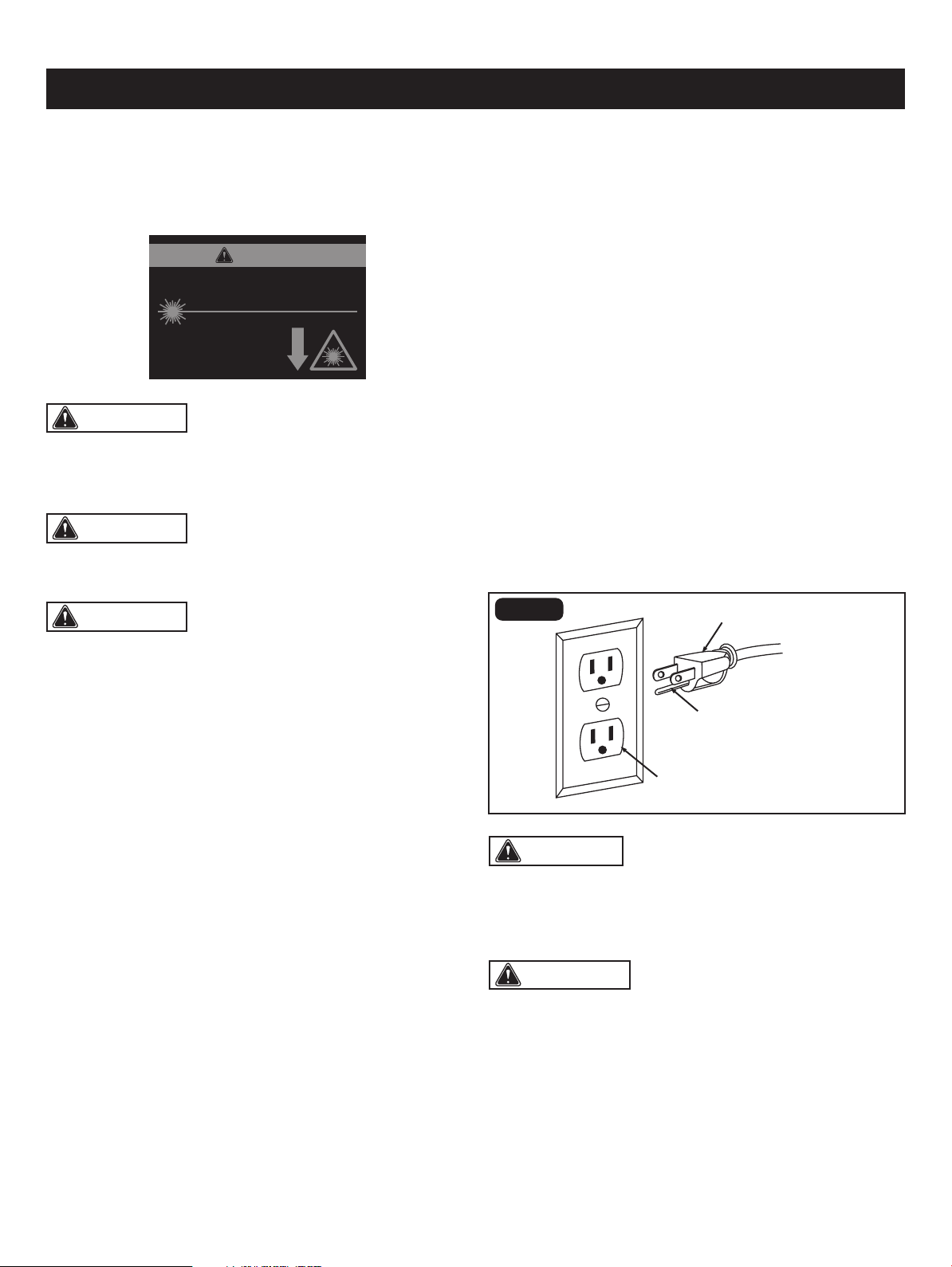
Check with a qualied electrician or service technician
if the grounding instructions are not completely understood,
or if in doubt as to whether the tool is properly grounded.
Use only three-wire extension cords that have three-prong
grounding plugs and three-pole receptacles that accept the
tool's plug, as shown in Fig. 1. Repair or replace a damaged
or worn cord immediately.
Improper connection of the equipment-grounding conductor
can result in a risk of electric shock. The conductor with
a green outer surface, with or without yellow stripes, is the
equipment-grounding conductor. If repair or replacement
of the electric cord or plug is necessary, do not connect the
equipment-grounding conductor to a live terminal.
Do not modify the plug provided. If it will not t the outlet,
have the proper outlet installed by a qualied electrician.
an electric cord having an equipment-grounding conductor
and a grounding plug. The plug must be plugged into
a matching outlet that is properly installed and grounded in
accordance with all local codes and ordinances.
WARNING: LASER LIGHT. LASER RADIATION.
Avoid direct eye exposure. Do not stare into the beam. Only
turn the laser beam on when the laser will shine on a work
piece.
laser light. Be aware of the laser light location when using
the tool. Always make sure that any bystanders in the
vicinity of use are made aware of the dangers of looking
directly into the laser.
WARNING: Use of controls, adjustments or
performance of procedures other than those specied in
this manual may result in hazardous radiation exposure.
SAFETY INSTRUCTIONS
Page 7
In the event of a malfunction or breakdown, grounding
provides a path of least resistance for electric current to
reduce the risk of electric shock. This tool is equipped with
GROUNDING INSTRUCTIONS
• The laser should be used and maintained in accordance
with the manufacture’s instructions.
• Never aim the beam at any person or any object other
than the work piece.
• Always ensure that the laser beam is aimed at a sturdy
work piece without a reective surface. Wood or
roughcoated surfaces are acceptable. Bright, shiny
reective surfaces are not suitable for laser use, because
the reective surface could reect the beam back at the
operator.
• Do not attempt to activate the laser when the tool housing
is removed.
• The laser is activated with a button switch that is
independent of the main switch for the drill press.
• Do not replace the laser guide assembly with a different
type. Any repairs must be carried out by the laser
manufacturer or a qualied service technician.
• Do not attempt to repair the laser guide by yourself.
• Do not attempt to change any parts of the laser guide.
CAUTION: In all cases, verify that the outlet in
question is properly grounded. if you are not sure, have a
licensed electrician check the outlet.
FIG. 1
This tool has a precision-built electric motor. It should be
connected to a power supply that is 120 volts, 60 Hz. A
substantial voltage drop will cause a loss of power and the
motor will overheat. If the tool does not operate when plugged
into an outlet, double check the power supply.
ELECTRICAL CONNECTION
WARNING: Do not permit ngers to touch the
terminal or the plug when installing or removing the plug
from an outlet.
Three-prong plug
Grounding prong
Properly grounded outlet
WARNING: The use of optical instruments to view
the laser beam, including but not limited to telescopes or
transits, will increase eye hazard.
LASER RADIATION. DO NOT STARE INTO BEAM OR
VIEW DIRECTLY WITH OPTICAL INSTRUMENTS.
Avoid exposure: Laser radiation
is emitted from this aperture.
Wavelength: 650 nm Max. Output < 1 mW
Class II Laser Product Complies with 21
CFR 1040.10 & 1040.11
CAUTION
Page 8
SAFETY INSTRUCTIONS
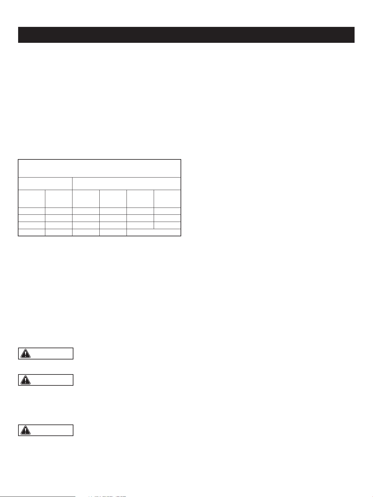
The table below shows the correct size to use, depending
on the cord length and nameplate amperage rating. If
in doubt, use the next heavier gauge. The smaller the gauge
number, the heavier the cord.
Use a proper extension cord. Make sure extension cords
are in good condition. When using an extension cord, be
sure to use a cord that is heavy enough to carry the drawn
current needed by the saw. An undersized cord will cause
a drop in line voltage, resulting in loss of power and
overheating.
GUIDELINES FOR EXTENSION CORDS
Be sure extension cords are properly wired and in good
condition. Always replace a damaged extension cord
or have it repaired by a qualied technician before using it.
Protect extension cords from sharp objects, excessive heat,
and damp or wet areas.
WARNING: Keep the extension cord clear of the
working area. Positon the cord so that it will not get caught
on lumber, tools, or other obstructions while you are working
with a power tool. Failure to do so can result in serious
personal injury.
WARNING: Check extension cords before each
use. If damaged replace immediately. Never use tool with
a damaged cord since touching the damaged area could
cause electrical shock resulting in serious injury.
WARNING: To avoid electrical hazards, re hazards,
or damage to the tool, use proper circuit protection.
Use a separate electrical circuit for power tools. This circuit
should be protected with a time delayed fuse. Before
connecting the tool to the power line, make sure the switch
is in the OFF position and the electric current is rated the
same as the current stamped on the motor’s nameplate.
Running at a lower voltage will damage the motor.
MINIMUM GAUGE (AWG)
EXTENSION CORDS (120V use only)
Amperage rating
Total length
Not Recommended
Not more
than
25'
(7.5 m)
6 18
50'
(15 m)
16
100'
(30 m)
16
150'
(45 m)
14
More
than
0
10 18 16 14 126
12 16 16 14 1210
16 14 1212
The safe use of this product requires an understanding of
the information on the tool and in this operator’s manual as
well as a knowledge of the project you are attempting.
Before use of this product, familiarize yourself with all
operating features and safety rules.
GLOSSARY OF TERMS
• Revolutions Per Minute (RPM): The number of turns
complete by a spinning object in one minute.
• Pulley Housing Cover: Covers pulleys and belt during
operation of drill press.
• Pilot Hole: A small hole drilled in a workpiece that serves
as a guide for drilling large holes accurately.
• Belt Tension Lock Knobs: Tightening knobs lock motor
bracket support to maintain correct belt distance and
tension.
• Head Lock Set Screws: Locks the head to the column.
ALWAYS have them locked in place while operating the
drill press.
• Table Support: Rides on column to support table.
• Column Support: Supports column and provides mounting
holes for column to base.
• Support Lock Handle: Tightening locks table support to
column. Always have it locked in place while operating the
Drill Press.
• Base: Supports Drill Press. For additional stability, holes
are provided in base to bolt Drill Press to bench. (See
“SPECIFIC SAFETY RULES”).
• Feed Return Spring and Cover: Provides means to adjust
quill spring tension.
• Depth Scale: Shows depth of the hole being drilled in
inches.
• Column: Connects head, table, and base on a one-piece
tube for easy alignment and movement.
• Rack: Combines with gear mechanism to provide easy
elevation of the table by the hand operated table bevel
lock.
• Rack Collar: Holds the rack to the column. The rack
remains movable in the collar to permit table support
movements.
• Bevel Scale: Shows degree table is tilted for bevel
operations. Scale is mounted on table support.
• Table Bevel Lock: Locks the table in any position from
0°-45°.
• Table: Provides working surface to support workpiece.
The table of your drill press rotates 360˚ and bevels up to
45˚ for angle drilling.
• Chuck: Clamping devise connected to the spindle to hold
the drill bit or cutting tool.
• Chuck Key: Key used to loosen and tighten the chuck.

Page 9
SAFETY INSTRUCTIONS
• Feed Handle: Moves the chuck up or down. One or two
of the handles may be removed if necessary whenever the
workpiece is of such unusual shape that it interferes with
the handles.
• Drill Bit: Cutting tools used to create cylindrical holes.
• ON/OFF Switch: The ON/OFF switch located on the front
of the drill press allows the operator to turn ON/OFF the
drill press easily. To lock the switch in the OFF position,
remove the safety key from the switch. Place the safety
key in a location that is not accessible to children and
others who are not qualied to use the tool.
• Pulley: Spindle or motor mounted wheel with groves along
its edge to accept a drive belt for the purpose of control
speed.
• Quill: Feed tube used to control vertical movement of the
spindle.
• Spindle Speed: Five different spindle speeds allow you
to drill a wide variety of material including wood, plastic
and metal.
• Spindle: Shaft rotating on a vertical axis in which the
chuck is attached.
• Workpiece: The item which the cutting operation is being
applied too.
• Backup Material: A piece of scrap wood placed between
the workpiece and table. The backup board prevents wood
in the workpiece from splintering when the drill passes
through the backside of the workpiece. It also prevents
drilling into the table top.
• Motor: Your drill press is equipped with an industrial-duty
induction motor for long-lasting, smooth performance.
• LED Worklight: Unique LED worklight illuminates work
surface under low light conditions. The worklight turns on
with the LED worklight switch.
• Laser Guide: For more accurate cuts, a laser guide is
included with your Drill Press. When used properly, the
laser guide makes accurate, precision cutting simple and
easy.
Page 10
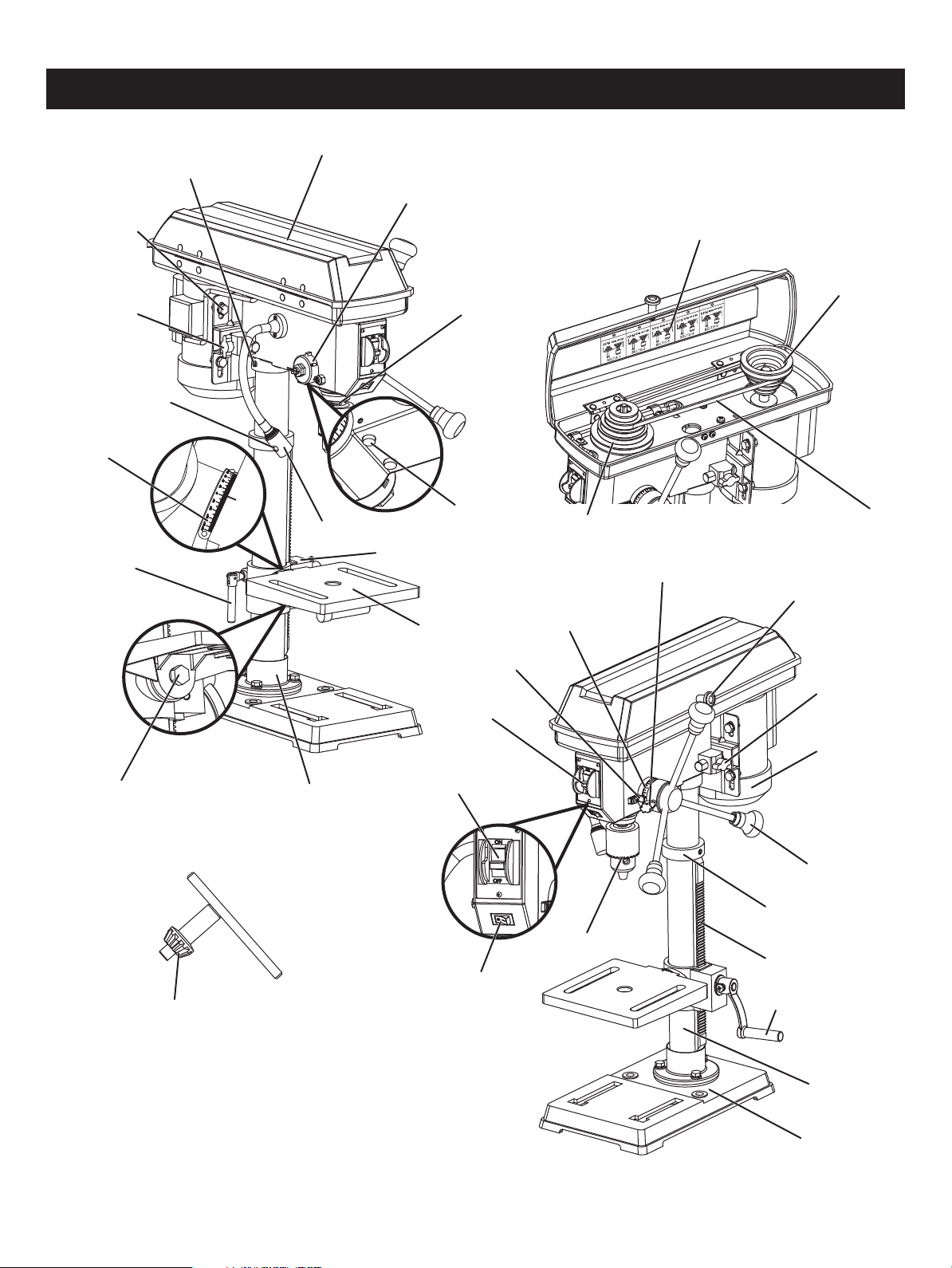
OVERVIEW
LED worklight
Locking screw
Belt tension
lock knob
Head lock set screw
Pulley housing cover
Belt/pulley speed chart
Pulley housing knob
Motor pulley
Chuck
Belt
Belt tension
lock knob
Motor
Feed handle
Rack collar
Rack
Base
Support lock handle
Spindle pulley
Column
Table
Pointer
Depth tension knob
Bevel scale
Column lock handle
Depth scale
Safety key
ON/OFF switch
LED light switch
Table bevel lock Column support
Chuck key
Laser switch
Feed return spring
and cover
Quill
Table support
Laser

Motor
Pulley speeds
Table size
Base size
Spindle travel
620, 1150, 1630, 2180, 3070 RPM (no load)
Laser Wavelength: 650 nm, Max. Output<1 mw Class II
LED Light Yes
120 V~ 60 Hz 4.1A
7 1/4 x 7 1/ 4 in. (18.4 x 18.4 cm)
13 3/8 x 8 1/4 in. (34 x 21 cm)
2 3/8 in. (6 cm)
Column diameter ø2 in. (5 cm)
5/8 in. (1.6 cm) diameter
Max. drilling capacity
5 in. (12.7 cm) chuck to column
12 3/16 in. (31 cm) chuck to table
17 1/4 in. (43.8 cm) chuck to base
1/16-5/8 in. (0.15-1.6 cm), keyed
Weight
Chuck
47.3 lbs (21.5 kg)
Page 11
SPECIFICATIONS
Page 12
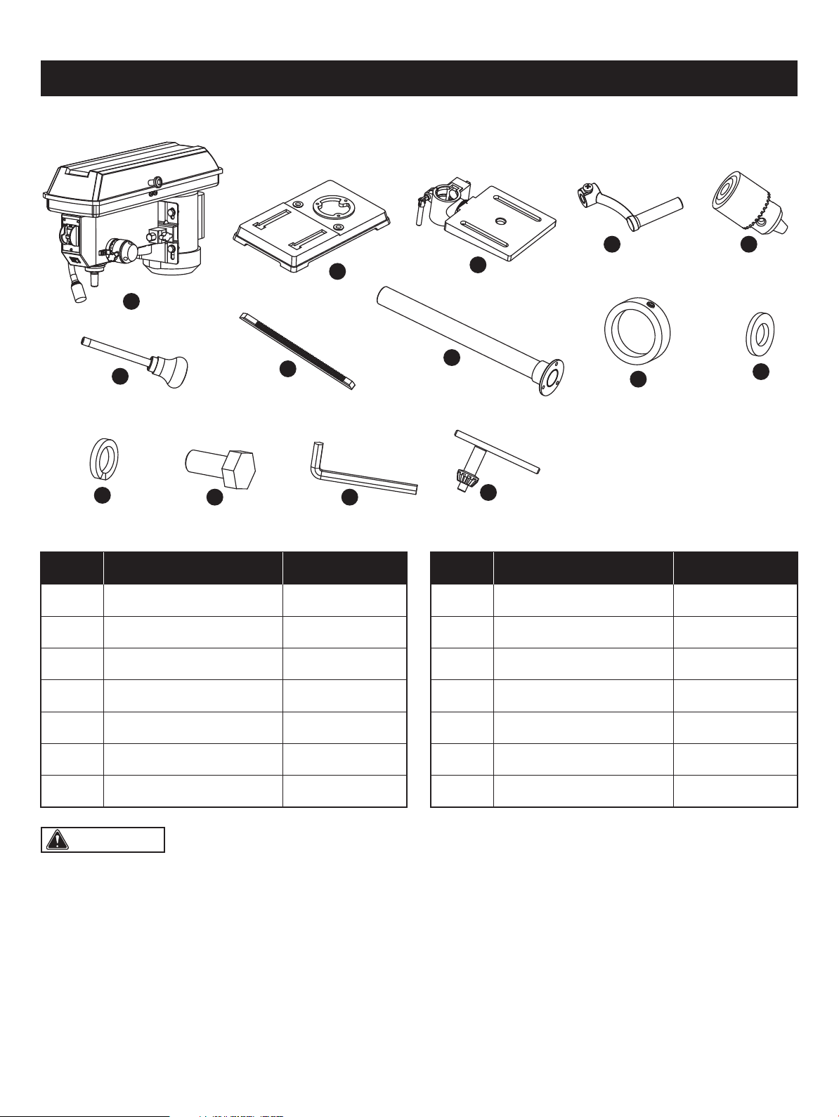
CONTENTS
WARNING: The use of attachments or accessories not listed in this manual might be hazardous and could cause
serious personal injury.
A 1
B 1
C 1Table/Support Assembly
Base
Head Assembly
Support Lock HandleD 1
E 1Chuck
Rack
Feed Handle
1
3
The following items are included with your drill press:
A
F
K
L M
N
G
H
I
J
B
C
D E
PART DESCRIPTION QUANTITY
3
I
J
Spring Washer 8
Flat Washer 8
Rack Collar
1H Column/Support Assembly
3
K
Hex Bolts M8 x 25
1
L
4mm Hex Key
Chuck Key
F 3
M
N
1G 1
PART DESCRIPTION QUANTITY
Page 13
ASSEMBLY
FIG. 4a
A
D
C
E
B
WARNING: To avoid injury, do not connect this
drill press to a power source until it is completely assembled
and adjusted and you have read and understood the
operator’s manual.
(ITEMS NOT SUPPLIED)
Star-head screwdriver
13mm Open-end wrench or adjustment wrench
Hammer or rubber mallet
Framing square
Ruler
(ITEMS SUPPLIED)
4mm Hex key (1 pc)
Chuck key
Block of wood
UNPACKING YOUR DRILL PRESS
YOU WILL NEED
Do not use this product if any parts of the package contents are already assembled to your product when you unpack it.
Package contents are not assembled to the product by the manufacturer and require customer installation. Use
of a product that may have been improperly assembled could result in serious personal injury.
• Carefully remove all parts from the shipping carton.
• Carefully lift tool from the carton and place it on a level work surface.
• Inspect the tool carefully to make sure that no breakage or damage occurred during shipping.
• Do not discard the packing material until you have carefully inspected and satisfactorily operated the tool.
• Remove the protective oil that is applied to table, base and column. Use any ordinary household grease and spot remover.
• Apply a coat of paste wax to the table, column and machined surfaces of base to prevent rust. Wipe all parts thoroughly
with a clean, dry cloth.
• If any parts are damaged or missing, please call 1-877-684-8912 for assistance.
WARNING: The use of attachments or accessories not listed in this manual might be hazardous and could cause
serious personal injury.
WARNING: Do not attempt to modify this tool or create accessories not recommended for use with this tool. Any
such alteration or modication is misuse, and could result in a hazardous condition leading to possible serious personal
injury.
WARNING: Do not connect to the power supply until assembly is complete. Failure to comply could result in
accidental starting and possible serious personal injury.
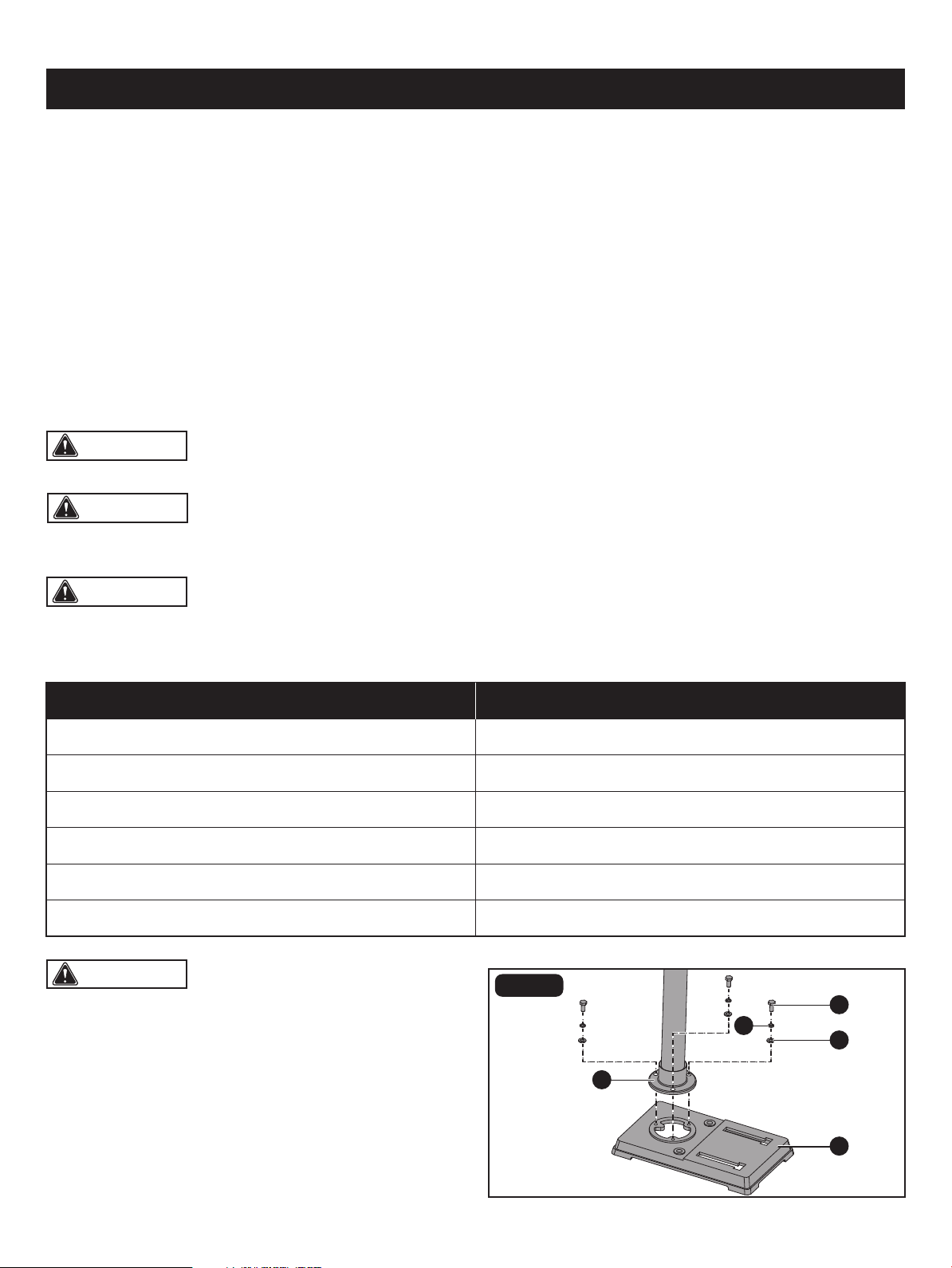
BASE TO COLUMN (Fig. 2)
• Set the base (A) on the oor.
• Place the column/support assembly (B) on the base (A),
align the column support holes with the base holes.
• Install a hex bolt M8 x 25 (C), a at washer 8 (D) and a
Page 14
ASSEMBLY
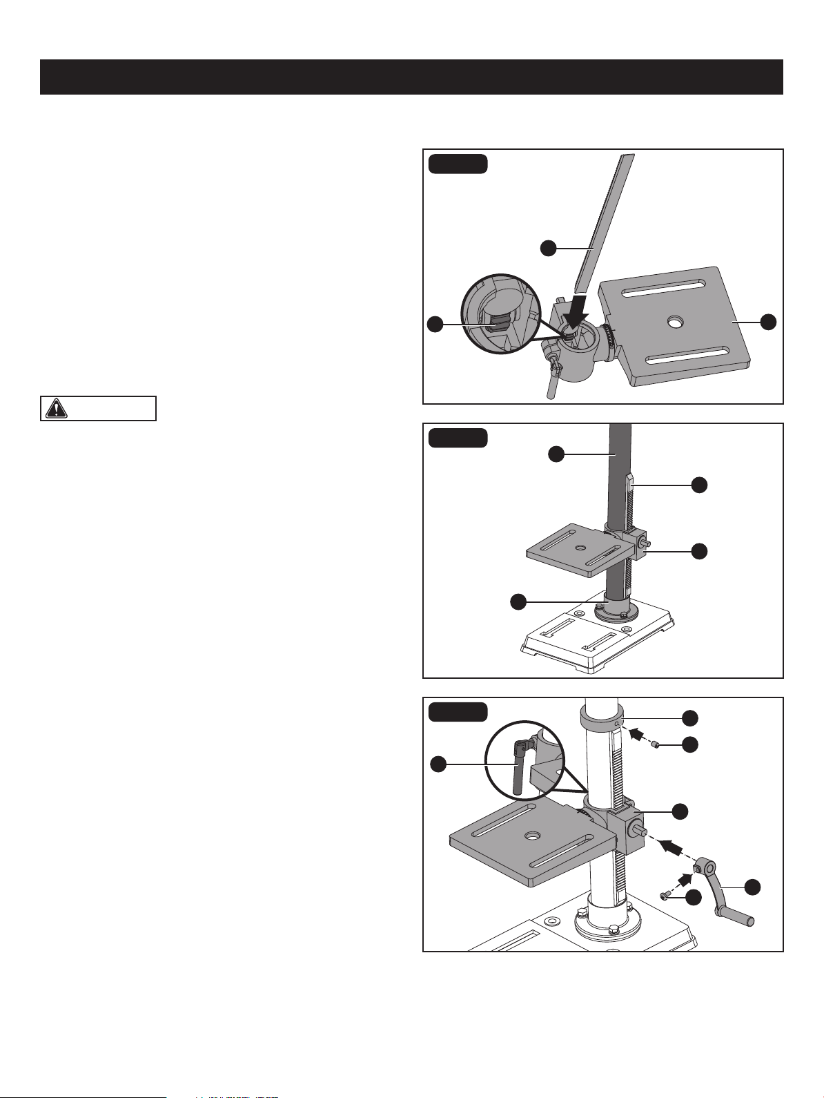
CAUTION: Make sure there is enough clearance to
allow the table to rotate around the column. The collar must
sit loosely over the rack and not angled on the column. To
avoid column or collar damage, only tighten the set screw
enough to keep collar in place.
FIG. 3a
FIG. 3b
FIG. 3c
B
A
F
G
I
B
H
B
A
D
E
J
C
spring washer 8 (E) in each column support hole and tighten with the wrench.
TABLE TO COLUMN (Fig. 3a-3c)
• Insert the rack (A) into the geared groove of the table
support (B). Make sure the worm shaft (C) on the inside
of table support is engaged with the teeth of the rack. The
table support should sit at the center of the rack.
• Slide the rack and table support assembly (A, B) down
together onto the column (D). Insert the bottom edge of
the rack into the lip of the column support (E). HOLD IN
THIS POSITION until the next step is completed.
• Place the rack collar (F) bevel side down over the rack.
Tighten the set screw (G) with 3mm hex key to hold the
rack in position.
• Insert the table support lock handle (H) onto the shaft on
the side of the table support (B). Make sure the set screw
(I) is aligned on the at of the shaft and as close to the
table support as possible. Tighten the set screw (I).
• Position the table in the same direction as the base, and
tighten the column lock handle (J).
Page 15
ASSEMBLY
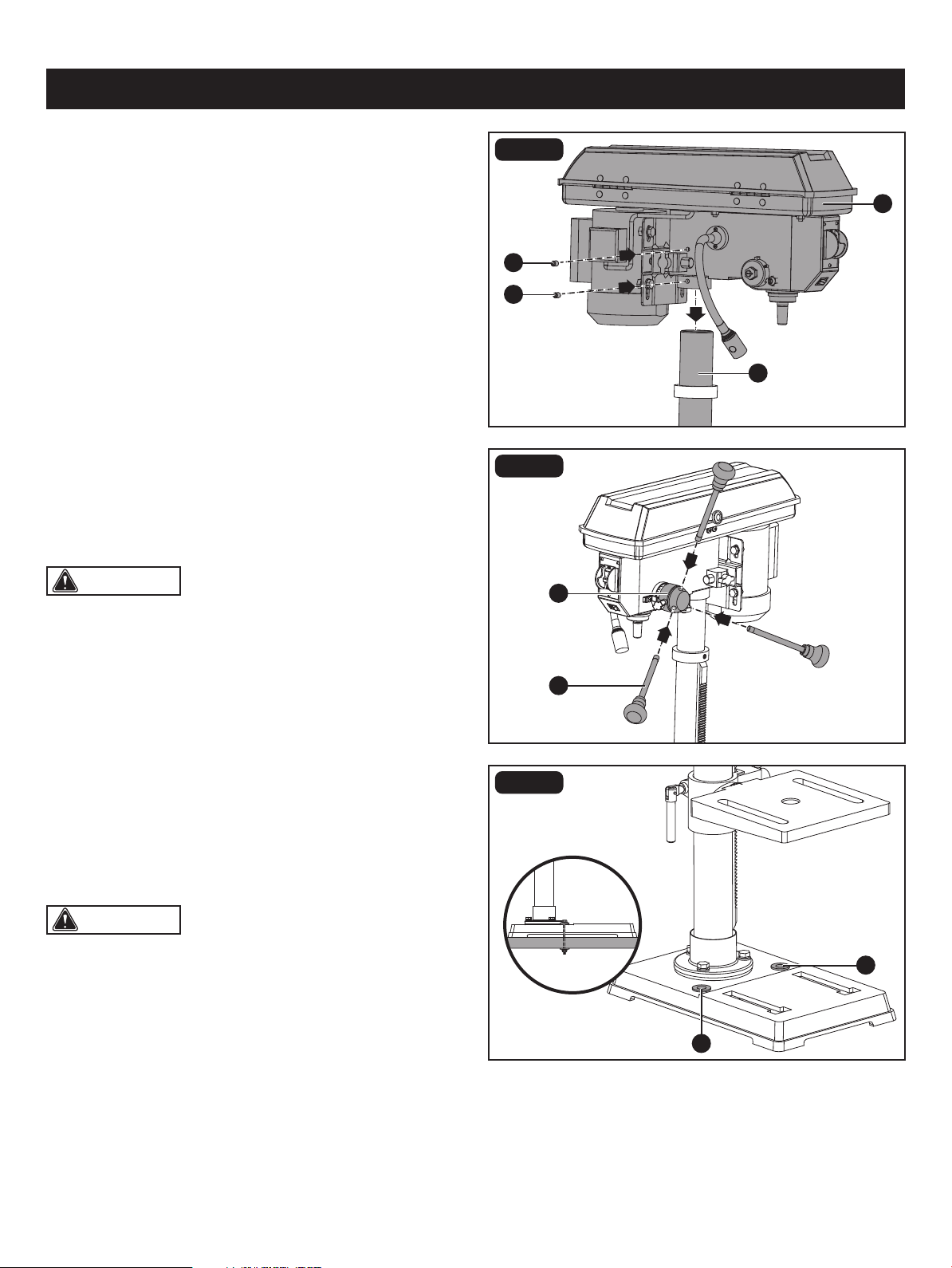
CAUTION: One or two of the feed handles may be
removed if an unusually-shaped workpiece interferes with
handle rotation.
CAUTION: If the stand or workbench has a tendency
to move during operation, fasten it securely to the oor.
FIG. 4
FIG. 5
DRILL PRESS HEAD TO COLUMN (Fig. 4)
• Lift the drill press head assembly (A) carefully and place
the mounting hole of the drill press head onto the top of
the column (B). Make sure the head is seated properly on
the column.
• Align the direction of the drill press head with the direction
of the base and table.
• Tighten the two set screws (C) using the 4mm hex key.
FEED HANDLES (Fig. 5)
• Thread the three feed handle rods (A) into the holes on
the feed hub (B).
• Hand tighten.
FIG. 6
MOUNTING THE DRILL PRESS (Fig. 6)
Your drill press must be securely fastened through the
mounting holes (A) to a stand or workbench with heavy-duty
fasteners. This will prevent the drill press from tipping over,
sliding or walking during operation.
A
B
B
A
A
A
C
C
Page 16
ASSEMBLY
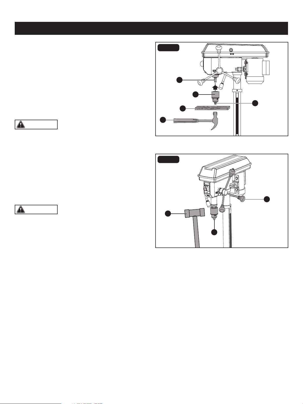
CAUTION: To avoid damaging the chuck, make
sure the jaws are completely recessed into the chuck. Do
not use a metal hammer directly to drive the chuck onto the
spindle.
CAUTION: To avoid possible damage, be prepared
to catch the as chuck it falls.
C
A
B
A
FIG. 7
INSTALL THE CHUCK (Fig. 7)
• Inspect and clean the taper hole in the chuck (A) and the
spindle (B). Remove all grease, coatings, and particles
from the chuck and spindle surfaces with a clean cloth.
• Open the chuck jaws (C) by turning the chuck barrel
clockwise by hand. Make sure the jaws are completely
recessed inside the chuck.
• Seat the chuck on the spindle by placing a block of wood
(D) under the chuck (A) and tapping the wood with
a hammer (E) or tap the chuck with a rubber mallet.
FIG. 8
REMOVE THE CHUCK (Fig. 8)
• Turn the feed handles (A) to lower the chuck (B) to the
lowest postion.
• Place a ball joint separator (not shown) above the chuck
and tap it lightly with a rubber mallet (C) to cause the
chuck to drop from the spindle.
E
C
B
D
RPM 60Hz∞620
BELT: A-1
E
D
C
B
A
5
4
3
2
1
E
D
C
B
A
5
4
3
2
1
E
D
C
B
A
5
4
3
2
1
E
D
C
B
A
5
4
3
2
1
E
D
C
B
A
5
4
3
2
1
BELT: B-2 BELT: C-3 BELT: D-4 BELT: E-5
RPM 60Hz∞1150 RPM 60Hz∞1630 RPM 60Hz∞2180 RPM 60Hz∞3070
1 2 3 4 5
ADJUSTMENTS
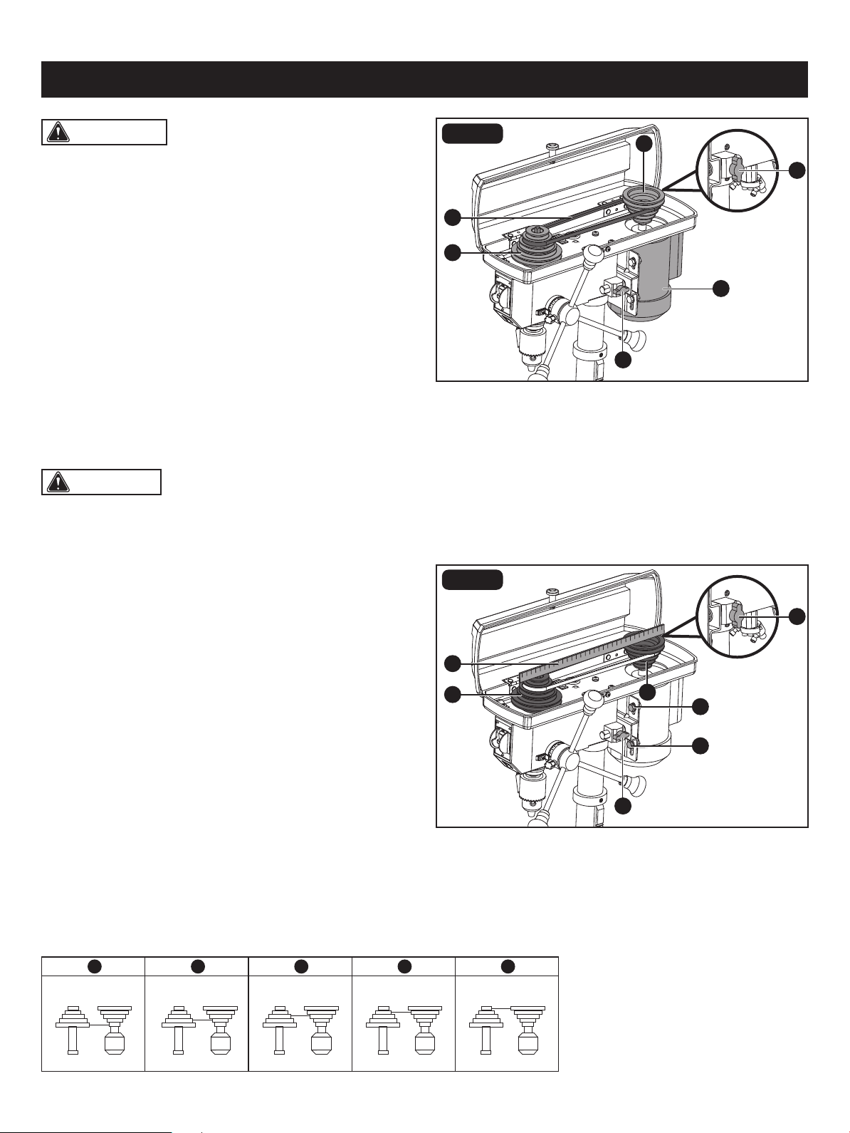
CAUTION: The belt (D) should be tight enough to
prevent slippage. Correct tension is set if the belt exes
about 1/2 in. (13 mm) when thumb pressure is applied at
the midpoint of the belt between the pulleys.
Page 17
INSTALL THE BELT (Fig. 9)
ASSEMBLY ADJUSTMENTS
• Open the pulley housing cover.
• Loosen the belt tension lock knobs (A) on both sides of
the drill press.
• Slide the motor (B) as close to the drill press head
as possible.
• Place a belt (C) on the motor pulley (D) and the spindle
pulley (E) in the proper position for the desired speed.
• Pull the motor away from the drill press head until the belt
is properly tensioned. Tighten the belt tension lock knobs
(A).
ALIGN THE BELT PULLEYS (Fig. 10)
• Check the alignment of the pulleys with a straight edge
of ruler (A) by laying the straight edge across the top of
the motor pulley (B) and spindle pulley (C).
• If the pulleys are NOT aligned, release belt tension
by loosening the belt tension lock knobs (D) on both sides
of the head.
• Loosen the motor mount nuts (E) with an adjustable
wrench or 13mm open-end wrench, and lower or raise the
motor until the pulleys are aligned.
• Tighten the motor mount nuts (E) with an adjustable
wrench or 13mm open-end wrench to maintain the
position.
• Lock the motor for the proper belt tension and tighten the
tension lock knobs (D).
WARNING: To prevent personal injury, always
disconnect the plug from the power source when making
any adjustment.
B
A
D
E
C
A
FIG. 9
D
B
C
A
D
E
E
FIG. 10
SPINDLE SPEEDS
This drill press offers ve spindle speeds from 620 to 3070 RPM. The highest speed is obtained when the belt is positioned
on the largest motor pulley step and the smallest spindle pulley stop.
CAUTION: To reduce the risk of injury, keep pulley
housing cover in place and in proper working order when
operating.
Page 18
ADJUSTMENTS
B
B
E
A
A
B
C
D
A
C
E
A
FIG. 11
FIG. 12
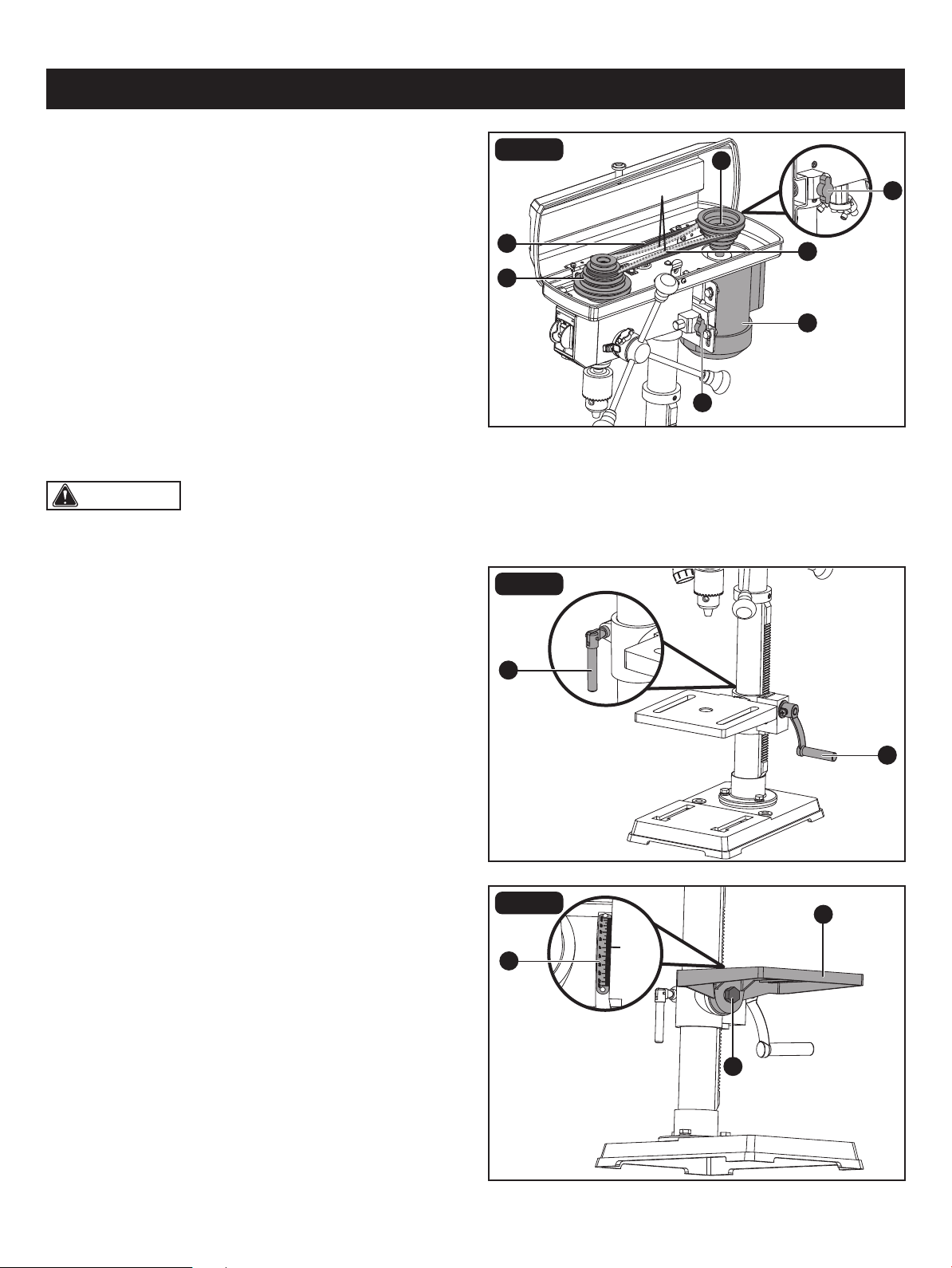
ADJUST SPEEDS AND TENSION THE
BELT (Fig. 11)
• Open the drill press pulley housing cover.
• Loosen the belt tension knobs (A) on both sides of the
drill press head.
• Pull the motor (B) towards the drill press head.
• Set the belt on the desired steps of the motor pulley (C)
and spindle pulley (D) according to the belt positions on
the spindle speed chart on Page. 17.
• Pull the motor away from the drill press head to increase
the belt tension. Tighten the tension knobs (A).
• The belt (E) should be tight enough to prevent slippage.
Correct tension is set if the belt exes about 1/2 in. (13 mm)
when thumb pressure is applied at the midpoint of the
belt between the pulleys.
ADJUSTMENTS TO RAISE OR LOWER
TABLE (Fig. 12)
FIG. 13
TO TILT THE TABLE (Fig. 13)
• Raise or lower the table by loosening the column lock
handle (A) and turning the support lock handle (B) until
the table is at the desired height.
• Tighten the column lock handle (A) before drilling.
• Rotate the table around the column by loosening the
column lock handle (A) and turning the table around the
column to the desired position.
• Tighten the column lock handle (A) before drilling.
The table can be tilted from 0-45° to the left and right.
• Loosen the table bevel lock (A) with the adjustment wrench.
• Tilt the table (B) to the desired angle, using the bevel
scale (C) as a basic guide.
• Re-tighten the table bevel lock (A).
• To return the table to its original position, loosen the table
bevel lock. Realign the bevel scale (C) to the 0° setting.
• Tighten the table bevel lock (A).
1/2 in.
CAUTION: Do not overtighten the two nuts. If the
nuts are tightened too much, the movement of the spindle
and feed handles will be sluggish.
Page 19
ADJUSTMENTS
D
C
C
B
A
A
B
D
A
C
E
E
B
FIG. 14
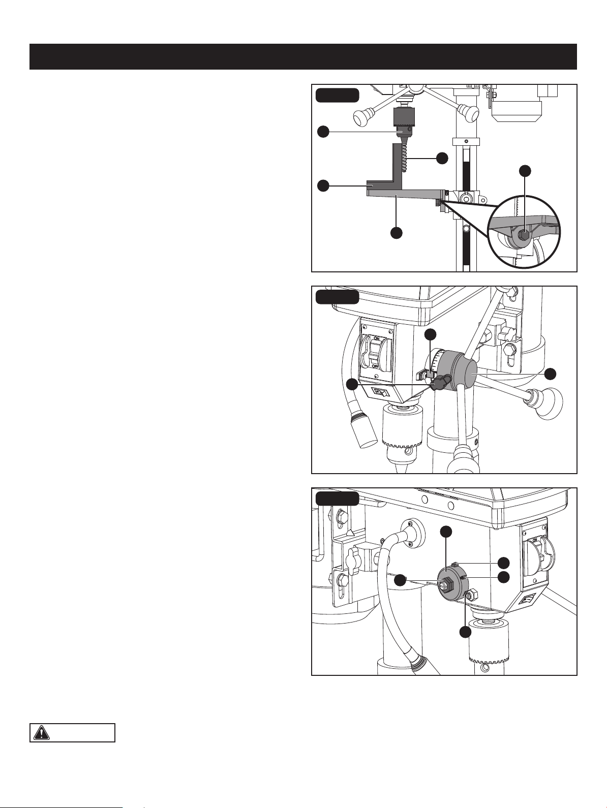
TO SQUARE THE TABLE TO THE HEAD
(Fig. 14)
• Insert a 3 in. (7.6 cm) drill bit (A) into the chuck (B) and
tighten.
• Raise and lock the table (C) about 1 in. (2.5 cm) from the
end of the drill bit.
• Place a combination square (D) on the table as shown.
The drill bit should be parallel to the straight edge of the
square.
• If an adjustment is needed, loosen the table bevel lock (E)
with a adjustment wrench.
• Square the table to the bit by tilting the table.
• Tighten the table bevel lock (E) when square.
FIG. 15
DRILLING DEPTH (Fig. 15)
• To stop the drill at a specic depth for consistent and
repetitive drilling, loosen the depth tension knob (A) located
on the depth scale hub (B).
• Turn the hub until the pointer (C) is aligned to the desired
depth on the scale.
• Tighten the depth tension knob (A). The chuck will stop
after traveling downward to the distance selected.
FIG. 16
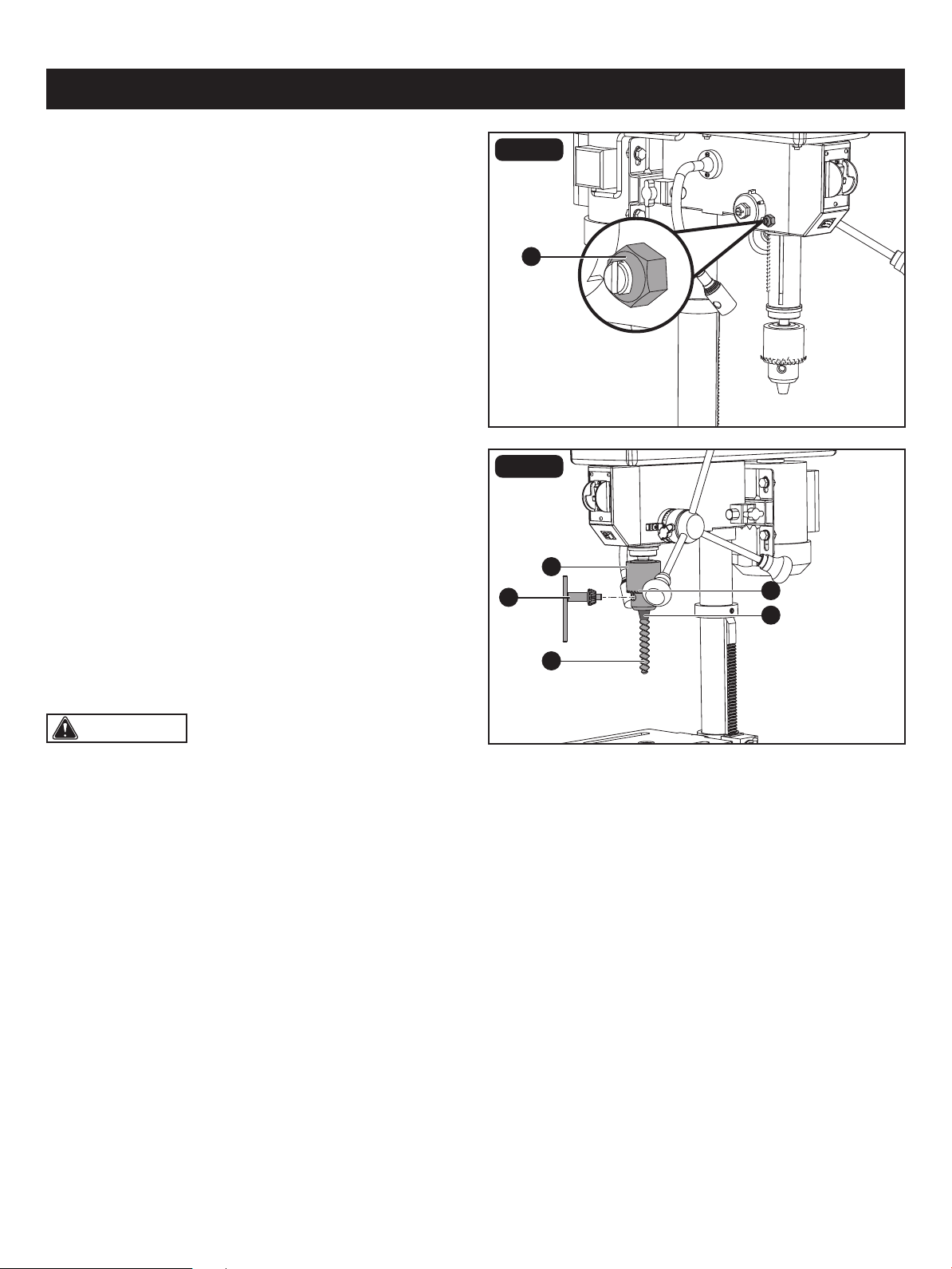
SPINDLE RETURN SPRING (Fig. 16)
The spindle is equipped with an auto-return mechanism.
The main components are a spring and a notched housing.
The spring was properly adjusted at the factory and should
not be readjusted unless absolutely necessary. If it needs
to be adjusted, proceed as follows:
• Unplug the drill press.
• Place a screwdriver into the loop (A) to hold the spring in
place.
• Loosen the two housing nuts (B) approximately 1/4 in.
(6 mm). Do not remove the nuts from the threaded shaft.
• While rmly holding the spring housing (C), carefully pull
it out until it clears the raised notch (D). Turn it until the
next notch (E) is engaged with the raised notch (to increase
the tension, turn it counter-clockwise; to decrease the
tension, turn it clockwise). Tighten the two housing nuts.
Page 20
WARNING:
• To reduce the risk of injury, only use the chuck key
provided with this drill press or a duplicate of it. This chuck
key is self-ejecting and will “pop” out of the chuck when
you let go. This action is designed to help prevent throwing
of the chuck key from the chuck when power is turned
“on”. Do not use any other key as a substitute; order a
new one if damaged or lost.
• To reduce the risk of injury, make sure the chuck key is
removed from the chuck before starting any drilling
operation.
A
A
E
B
D
C
FIG. 17
ADJUSTMENTS
ANGULAR PLAY OF THE SPINDLE
(Fig. 17)
Move the spindle to the lowest downward position and hold
in place. With your other hand, try to make it revolve around
its axis with a side motion. If there is too much play, proceed
as follows:
• Loosen the lock nut (A).
• Turn the screw clockwise to eliminate the play but without
obstructing the upward and downward motion of the
spindle (a little bit of play is normal).
• Tighten the lock nut (A).
FIG. 18
INSTALL DRILL BITS (Fig. 18)
• Place the chuck key (A) into the side keyhole of the chuck
(B), meshing the gear teeth (C).
• Turn the chuck key counter-clockwise to open the chuck
jaws (D).
• Insert a drill bit (E) into the chuck far enough to obtain
maximum gripping of the chuck jaws.
• Centre the drill bit in the chuck jaws before nal tightening
of the chuck.
• Use the chuck key for the nal tightening to make sure
the drill bit will not slip while drilling.
CAUTION: DO NOT OPERATE drill press until it has been assembled and installed. Read and follow all safety
rules within this Instruction Manual, failure to do may result in electric shock and/or serious personal injury.
CAUTION: ALWAYS REMOVE CHUCK KEY before connecting tool to power source.
Page 21
WARNING: RISK OF PERSONAL INJURY. NEVER PERFORM ANY DRILLING OPERATION FREEHAND (WITHOUT
WORKPIECE AGAINST THE TABLE). The bit could grab the workpiece if it slips or twists.
WARNING: RISK OF PERSONAL INJURY. ALWAYS DISCONNECT THE TOOL FROM THE POWER OUTLET
BEFORE MAKING ANY ADJUSTMENT, INSTALLING OR CHANGING BITS OR OTHER TOOLS.
A
A
B
FIG. 19
OPERATION
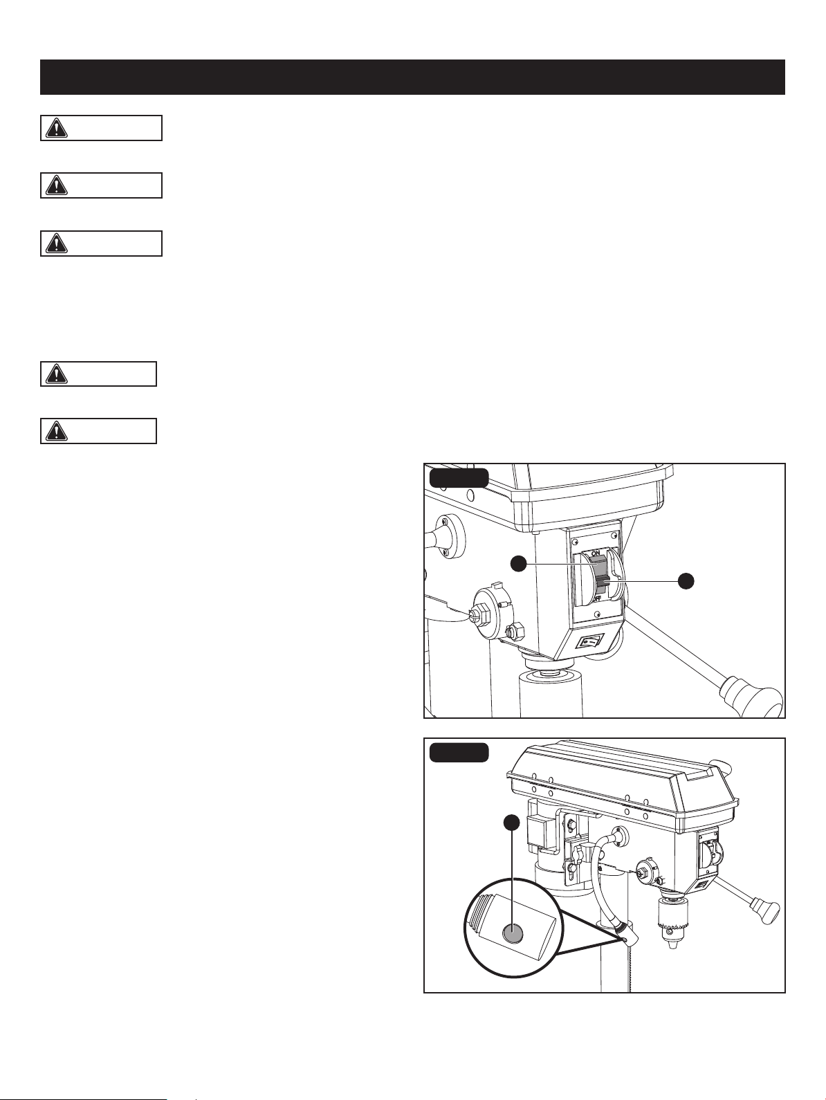
ON/OFF SWITCH (Fig. 19)
Drill press is equipped with an ON/OFF switch key. Removal
of the safe key prevents the drill from being turned ON.
Remove the key to avoid unintentional start up or
unauthorized use of the drill.
• To turn the drill press on, insert the safety key (A) into the
switch housing and move the ON/OFF (B) switch to the
ON position.
• To turn the drill press off, move the switch to the OFF
position.
• To lock the switch in the off position, remove the safety
key from the switch. Store the key in a safe place.
FIG. 20
LED LIGHT SWITCH (Fig. 20)
The LED light switch (A) is located on the side of the LED
light.
• Press the LED light switch to turn the LED light on.
• Press the LED light switch again to turn the LED light off.
WARNING: CHEMICAL HAZARD. FOLLOW ALL RECOMENDED SAFETY PRECAUTIONS WHILE OPERATING
THE DRILL PRESS. Some dust created by power sanding, grinding, drilling, and other construction activities contains
chemicals known to cause cancer, birth defects or other reproductive harm. Your risk from these exposures varies, depending
on how often you do this type of work. To avoid risk from exposure to these chemicals the following safety measures are
required during operation of this tool: Work in a well ventilated area and work with approved safety equipment, such as
those dust masks that are specially designed to lter out microscopic particles.
Page 22
WARNING: LASER RADIATION HAZARD. Do not
stare into the beam. Use of controls or adjustments or
performance of procedures other than those specied in
this instruction manual may result in hazardous radiation
exposure.
• Laser radiations on work table - Do not stare into reected
light from work surface.
• Avoid exposure - Laser light is emitted from the housing
front aperture. Do not stare into the aperture.
• Do not disassemble laser.
• Operate laser only when cutting. Turn laser off after use.
The laser drill guide will generate a red laser cross hair
line on the work surface. This line can be used to determine
where the bit will enter the workpiece for faster more
accurate drilling.
A
A
B
B
OPERATION
FIG. 21
FIG. 22
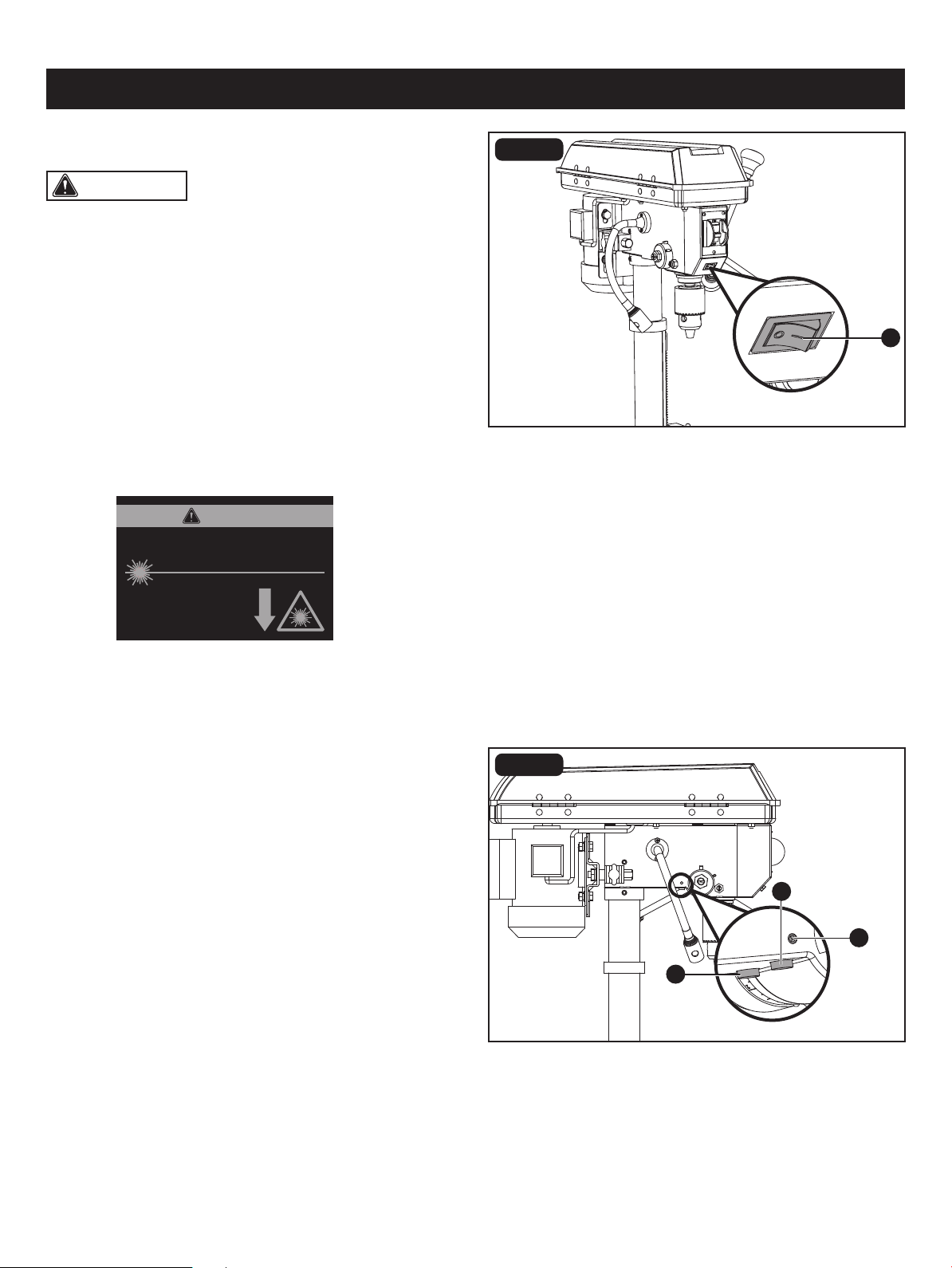
LASER LIGHT SWITCH (Fig. 21)
LASER LIGHT ALIGNMENT (Fig. 22)
The laser light switch (A) is located on the beside of the laser
ligth switch.
• To turn the laser light on, press the button “I”.
• To turn the laser ligth off, press the button “O”.
• Clamp a piece of scrap material to table below approximate
center line of the spindle. Lock the table.
• Insert a 1/16 in. twist drill into chuck. Start drill to conrm
bit is running straight without any wobble.
• Lower the bit into the scrap material enough to make a
small mark.
• Turn the laser on. Check to see if the cross hair is centered
in the mark.
• If it does not, loosen the laser adjustment screws (A) on
the each side of the machine body with 3mm hex
key supplied, adjust one or both laser emitters (B) until the
cross hair is centered in the mark.
• Tighten the adjustment screws.
LASER RADIATION. DO NOT STARE INTO BEAM OR
VIEW DIRECTLY WITH OPTICAL INSTRUMENTS.
Avoid exposure: Laser radiation
is emitted from this aperture.
Wavelength: 650 nm Max. Output < 1 mW
Class II Laser Product Complies with 21
CFR 1040.10 & 1040.11
CAUTION
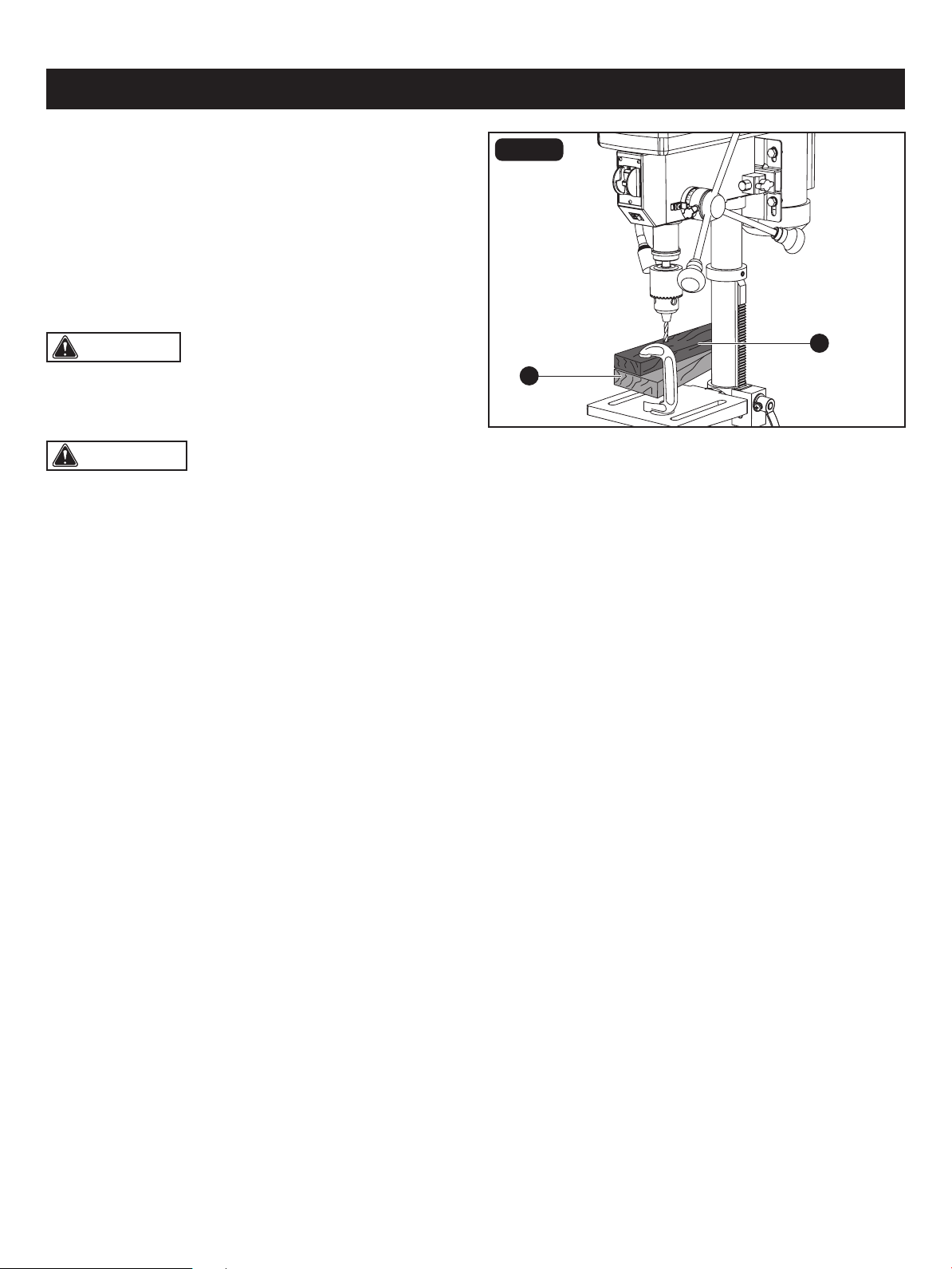
CAUTION: For small workpieces that cannot be
clamped to the table, use a drill press vise (optional
accessory, not included). The vise must be clamped or
bolted to the table to avoid injury.
Page 23
B
A
Always place a piece of backup material (A) (wood, plywood,
etc.) on the table underneath the workpiece (B). This will
prevent splintering on the underside of the workpiece as the
drill bit breaks through. To keep the material from spinning
out of control, it must contact the left side of the column as
illustrated, or be clamped to the table.
WARNING:
• To reduce the risk of injury, and the workpiece and the
backup material from being torn from your hand while
drilling, position them to the left side of the column. If the
workpiece and the backup material are not long enough
to reach the column, clamp them to the table. Failure to
do this could result in personal injury.
• To reduce the risk of injury, make sure the chuck key is
removed from the chuck before starting any drilling
operation.
• Feeding too slowly might cause the drill bit to burn.
• Feeding too rapidly might stop the motor, causing the belt or drill to slip, tearing the workpiece loose, or breaking the
drill bit.
• For deeper cuts, drill into the workpiece about 1/4" (6.4 mm) and raise the drill bit out of the workpiece. This will clear
chips out of the hole. Drill again another 1/4" (6.4 mm) and raise the drill bit out of the hole to clear debris and chips.
Repeat until nished drilling the hole. Practice with scrap material to get the feel of the machine before attempting to do
any regular drilling operation.
• When drilling metal, it will be necessary to lubricate the tip of the drill with oil to prevent overheating the drill bit.
OPERATION
FIG. 23
POSITION THE TABLE AND WORKPIECE
(Fig. 23)
Use a centre punch or sharp nail to dent the workpiece where you want the hole. With the switch off, bring the drill down
to the workpiece, lining it up with the hole location. Turn the switch on and pull down on the feed handles with only enough
effort to allow the drill to cut.
DRILLING A HOLE
Drilling a blind hole (not all the way through the workpiece) to a given depth can be done in two ways.
DRILLING A SPECIFIC DEPTH
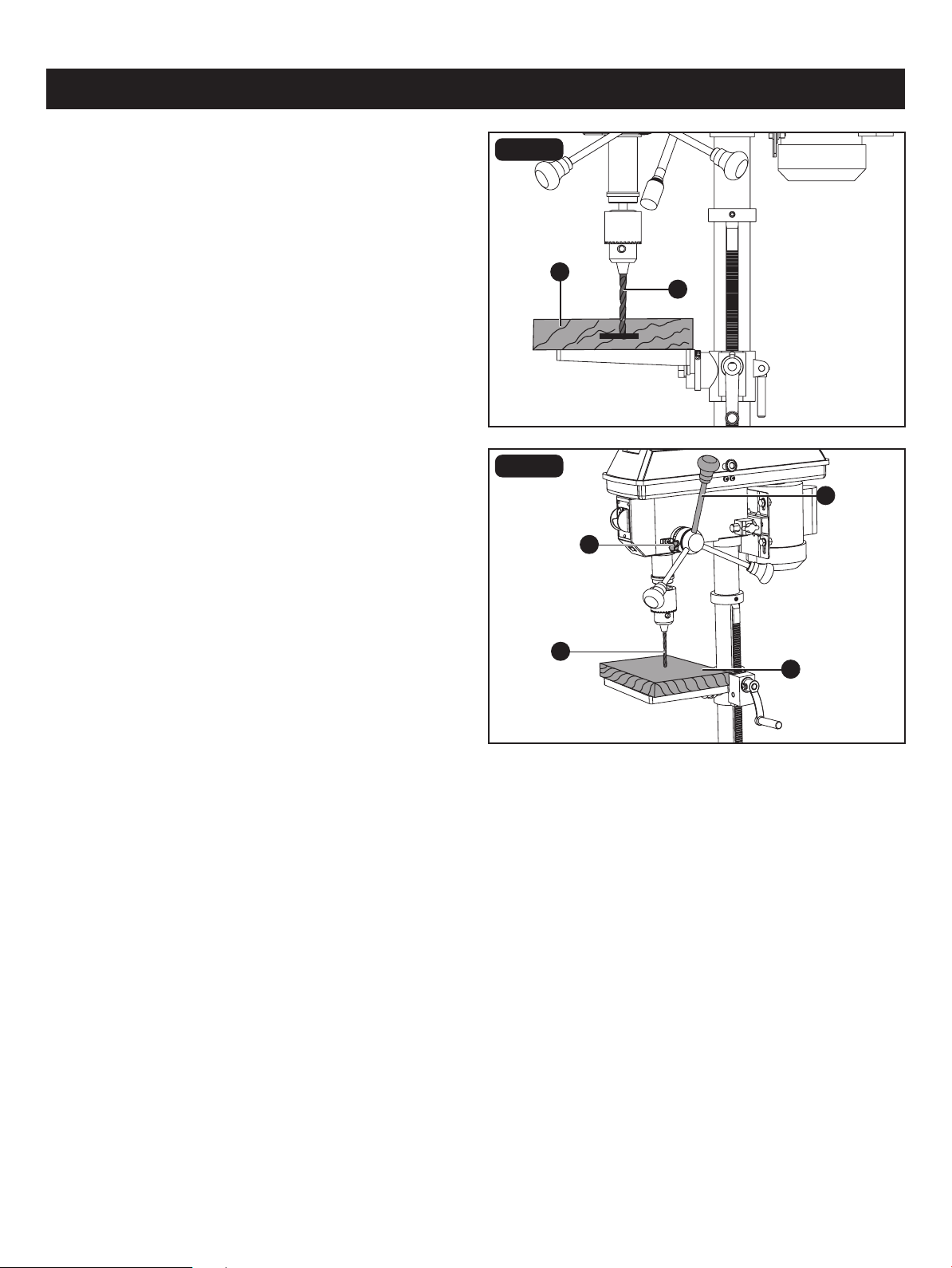
Page 24
• Mark the desired depth of the hole on the side of
the workpiece (A).
• With the switch off, bring the drill bit (B) down until the tip
is even with the mark.
• Hold the feed handle at this position.
• Lock the depth scale tension knob. The chuck and the
drill bit will now be stopped at the distance selected on
the depth scale.
B
C
A
B
D
A
OPERATION
FIG. 24
WORKPIECE METHOD (Fig. 24)
• With the switch off, turn the feed handle (A) until the drill
bit tip (B) slightly touches the top of the workpiece (C).
• Hold the feed handles in that position.
• Loosen the depth tension knob (D).
• Spin the depth scale hub until the desired drilling depth
is at the scale pointer.
• Lock the depth tension knob. The chuck and drill bit will
now drill into the workpiece only to the distance selected
on the depth scale.
FIG. 25
DEPTH SCALE METHOD (Fig. 25)
Important factors when determining the best drilling speed:
• Type of material
• Size of the hole to be drilled
• Type of drill bit or cutter
• Desired quality of the cut
Remember, smaller drill bits require greater speed than larger drill bits. Softer materials require greater speed than harder
materials.
DRILLING SPEEDS
GENERAL DRILLING GUIDELINES

Page 25
WARNING: To reduce the risk of injury, make sure the chuck key is removed from the chuck before starting any
drilling operation.
OPERATION
DRILLING METAL
• Use metal-piercing twist drill bits.
• It is always necessary to lubricate the tip of the drill with oil to prevent overheating the drill bit.
• All metal workpieces should be clamped down securely. Any tilting, twisting, or shifting causes a rough drill hole and
increases the potential of drill bit breakage.
• Never hold a metal with your bare hands. The cutting edge of the drill bit may seize the workpiece and throw it, causing
serious injury. The drill bit will break if the metal piece suddently hits the column.
• If the metal is at, clamp a piece of wood under it to prevent turning. If it cannot be laid at on the table, then it should
be blocked and clamped.
DRILLING WOOD
• Brad point bits are preferred. Metal piercing twist bits may be used on wood.
• Do not use auger bits. They turn so rapidly that they lift the workpiece off the table and whirl it around.
• Always protect the drill bit by positioning the table so the drill bit will enter the centre hole when drilling
through the workpiece.
• To prevent splintering, feed slowly when the bit is about to cut enough to the backside of the workpiece.
• To reduce splintering and protect the point of the bit, use scrap wood as a backing or a base block under the workpiece.
FEEDING THE BIT
• Pull down on the feed handles with only enough force to allow the drill bit to cut.
• Feeding too rapidly might stall the motor, cause the belt to slip, damage the workpiece, or break the drill bit.
• Feeding too slowly will cause the drill bit to heat up and burn the workpiece.

CAUTION: Certain cleaning agents and solvents damage plastic parts. Some of these are: gasoline, carbon
tetrachloride, chlorinated cleaning solvents, ammonia and household detergents that contain ammonia. Avoiding use of
these and other types of cleaning agents minimizes the probability of damage. To avoid shock or re hazard, if the power
cord is worn, cut or damaged in any way, have it replaced immediately.
WARNING: To reduce the risk of injury, turn power switch off and remove plug from the power source outlet
before doing maintenance on or lubricating your drill press.
WARNING: All repairs, electrical or mechanical, should be attempted only by trained technicians. Use only identical
replacement parts; any other may create a hazard.
Page 26
Frequently blow out or vacuum sawdust or metal chips that accumulate in and on the motor, pulley housing, table and
work surface.
A coat of furniture-type paste wax applied to the table, column, and machined parts of the base will help to keep these
surface clean.
The ball bearings in the spindle and the V-belt pulley assembly are greased and permanuntly sealed. Pull the spindle down
and oil the spindle sleeve moderately every three months.
MAINTENANCE
GENERAL MAINTENANCE

TROUBLESHOOTING
Noisy operation • Adjust tension
• Remove spindle/quill assembly lubricate
• Tighten pulley
• Replace bearing
• Incorrect belt tension
• Dry spindle
• Loose pulley
• Bad bearing
Excessive drill wobble • Tighten by pressing chuck down on table
• Replace spindle shaft or bearing
• Replace chuck
• Loose chuck
• Worn spindle shaft or bearing
• Bad chuck
PROBLEM PROBLEM CAUSE CORRECTIVE ACTION
Motor will not start • Check power cord
• Check motor connection
• Check switch connections
• Replace motor
• Replace switch
• Power supply
• Motor connection
• Switch connections
• Motor winding burned
• Bad switch
Drill binds in workpiece • Apply less pressure
• Check belt tension
• Tighten drill with key
• Change speed
• Excessive pressure on feed handle
• Loose belt
• Loose drill
• Speed too fast
Drill burns or smokes • Refer to speed chart
• Clean drill
• Check sharpness and taper
• Use lubrication while drilling
• Apply less pressure
• Incorrect speed, slow down RPM
• Chips are not discharging
• Dull drill or not cut properly for material
• Needs lubrication
• Feed pressure wrong
Table difcult to raise • Lubricate with light oil
• Loosen clamp
• Needs lubrication
• Table lock tightened
Page 27
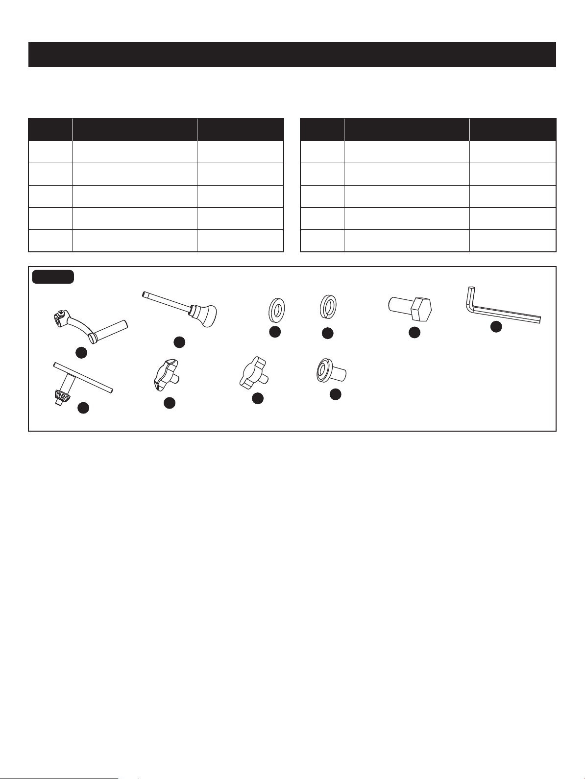
A
B
F
G
H
I
J
C
D
E
A 24037100001
24037100002
24037100003
24037100004
24037100005
24037100006
24037100009
24037100010
Support Lock Handle
Feed Handle
Flat Washer 8
Spring Washer 8
Hex Bolt M8 x 25
PART DESCRIPTION PART#
F
GB
J
C
D
E
Depth Tension Knob
Chuck Key 24037100007
H
4mm Hex Key
24037100008
I
Pulley Housing Knob
Belt Tension Lock Knob
PART DESCRIPTION PART#
For questions / comments, technical assistance or repair parts - Please call toll free at: 1-877-684-8912 (Monday - Friday
8am - 6pm EST.)
FIG. 14
Page 28
REPLACEMENT PARTS LIST

For questions / comments, technical assistance or repair parts – Please Call Toll
Free at: 1-877-684-8912 (Monday - Friday 8am – 6pm EST.)
Distributed by: Menard, Inc., Eau Claire, WI 54703
SAVE YOUR RECEIPTS
THIS WARRANTY IS VOID WITHOUT THEM
10" Drill Press with Laser
WARRANTY
TWO-YEAR LIMITED WARRANTY:
If, during normal use, this PERFORMAX™ power tool breaks or fails due to a defect
in material or workmanship within two years from the date of original purchase,
simply bring this tool with the original sales receipt back to your nearest Menards™
retail store. At its discretion, PERFORMAX™ agrees to have the tool or any defective
part(s) repaired or replaced with the same or similar PERFORMAX™ product or part
free of charge, within the stated warranty period, when returned by the original
purchaser with original sales receipt. This warranty; (1) excludes expendable parts;
(2) shall be void if this tool is used for commercial and/or rental purposes; and (3)
does not cover any losses, injuries to persons/property or costs. This warranty does
give you specic legal rights and you may have other rights, which vary from state
to state.