Loading ...
Loading ...
Loading ...
BNSTALLATiON STEP 6
Insfall t_e Door Contro/J
Locate door control within sight of door, at a minimum
height of 5 feet (1,5 m) where small children cannot reach,
away from moving parts of door and door hardware.,
If installing into drywall, drill 5/32" holes and use the
anchors provided. For pre-wired installations (as in new
home construction), it may be mounted to a single gang
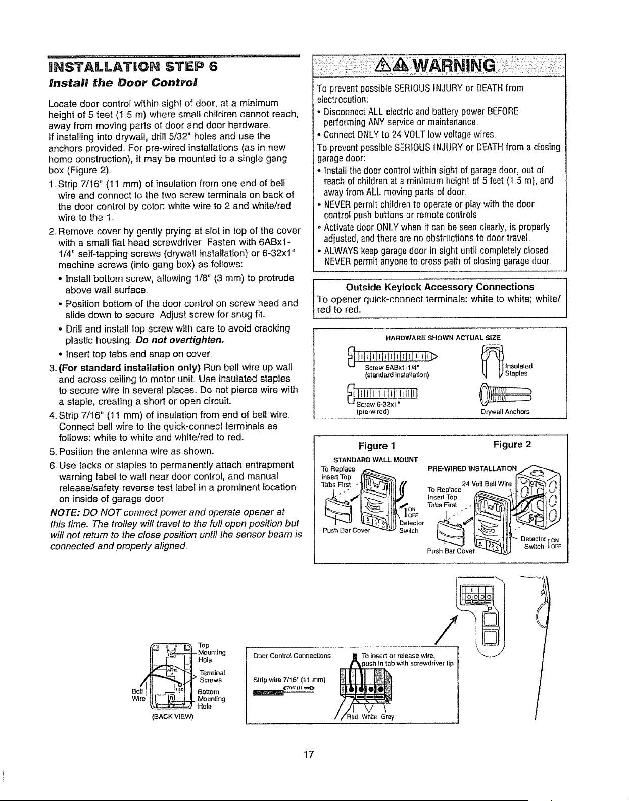
box (Figure 2).,
1,Strip 7/t6" (11 ram) of insulation from one end of bell
wire and connect to the two screw terminals on back of
the door control by color: white wire to 2 and white/red
wire to the 1.,
2, Remove cover by gently prying at slot in top of the cover
with a small flat head screwdriver, Fasten with 6ABx1-
1/4" setf4apping screws (drywall installation) or 6-32xl"
machine screws (into gang box) as follows:
- install bottom screw, allowing 1/8" (3 mm) to protrude
above walt surface,
• Position bottom of the door control on screw head and
slide down to secure.. Adjust screw for snug fit.,
o Drill and install top screw with care to avoid cracking
plastic housing., Do not overtighten.
• Insert top tabs and snap on cover•
3,,(For standard installation only) Run bell wire up wall
and across ceiling to motor unit° Use insulated staples
to secure wire in several places. Do not pierce wire with
a staple, creating a short or open circuit,,
4. Strip 7/16" (11 mm) of insulation from end of bell wire,
Connect bell wire to the quick-connect terminalsas
follows: white to white and white/red to red..
5, Position the antenna wire as shown,,
6, Use tacks or staples to permanently attach entrapment
warning label to wall near door control, and manual
release/safety reverse test label in a prominent location
on inside of garage door,.
NOTE: DO NOT connect power and operate opener at
this time., The trolley will travel to the full open position but
will not return to the close position until the sensor beam is
connected and properly aligned,
To preventpossibleSERIOUSIr_lJURYor DEATHfrom
electrocution:
. DisconnectALLelectric and battery power BEFORE
performingANYserviceor maintenance,
. ConnectONLYto 24 VOLTlow voltage wires.,
To preventpossibleSERIOUSINJURYor DEATHfrom a cfosing
garagedoor:
° Install the door control within sight of garagedoor, out of
reach of children at a minimum height of 5 feet (1.5 m), and
awayfromALL moving pads of door
. NEVERpermit childrento operateor playwith the door
controf push buttons or remote controls.
- Activatedoor ONLYwhen it can be seendearly, is properly
adjusted,and there areno obstructions to door travel,
° ALWAYSkeepgaragedoor in sight until completely closed..
NEVERpermitanyoneto cross path of closing garagedoor.,
Outside Keylock Accessory Connections
To opener quick-connectterminals: white to white; white/
red to red.,
HARDWARE SI-tOWN ACTUAL SiZE
(standard installation)
_ !i!l!illli*iiliHil
Screw 6_32x1"
(p_'e-wired) Drywall Anchors
Figure 1 Figure 2
STANDARD WALL MOUNT
To Replace
PBE_WtRED 1NSTALLATION_
tnserl Top lI_
Tabs First _,[
Push Bar Cover Switch
Push Bar Cover_ _ Switch
_,OFF
_Top
IF" \_1- Mounting
f - tJ] ,o,o
,_ _., Terminal
,,III Screws
Bet!lll_.,---__"_lII Bottom
w_,. _ HMoOUnt,ng
(BACK VIEW)
Door Controi Connections
Strip wi_e 7tl 6" (t 1 ram)
To insert or release wi_o,
1screwdriver tip
i..................
/
17
Loading ...
Loading ...
Loading ...