Loading ...
Loading ...
Loading ...
ENGLISH
6
SHOCKS Active Vibration Control®
System
For best vibration control, hold the tool as described in
Proper Hand Position and apply just enough pressure so
the damping device on the main handle is approximately
mid stroke. The hammer only needs enough pressure to
engage the active vibration control. Applying too much
pressure will not make the tool chip faster and active
vibration control will notengage.
DeWALT
Tool Tag Ready (Fig. A)
Optional Accessory
Your hammer comes with mounting holes
9
and fasteners
for installing a
DeWALT
Tool Tag. You will need a T15 bit tip
to install the tag. Only use the screws provided. The
DeWALT
Tool Tag is designed for tracking and locating professional
power tools, equipment, and machines using the
DeWALT
Tool Connect™ app. For proper installation and use of the
DeWALT
Tool Tag refer to the
DeWALT
Tool Tagmanual.
Electronic Speed and Impact Control
(Fig. A)
The electronic speed and impact control allows the use of
smaller chisels without the risk of chisel breakage, chipping
into light and brittle materials without shattering and
optimal tool control for precisechiseling.
To set the speed dial
8
, turn the dial to the desired level.
The higher the number, the greater the speed and impact
energy. Dial settings make the tool extremely flexible and
adaptable for many different appli cations. The required
setting depends on the chisel size and hardness of material
beingchipped.
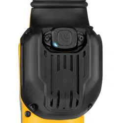
Mode Selection (Fig. E)
WARNING: Do not select the operating mode when
the tool isrunning. Tool must come to a complete stop
before activating the mode selector button or damage
to the tool mayresult.
Your tool is equipped with a mode selector dial
4
to
selectthe mode appropriate to desiredoperation.
Symbol Mode Application
Chisel
Adjustment
Chisel position
adjustment
Chipping
Light chipping, chiseling
and demolition
To select a mode
• Rotate the mode selector dial
4
so that the
arrow points to the symbol corresponding for the
desiredmode.
Fig. E
4
NOTE: The arrow on the mode selector dial
4
must be
pointing at a mode symbol at all times. There are no
operable positions inbetween.
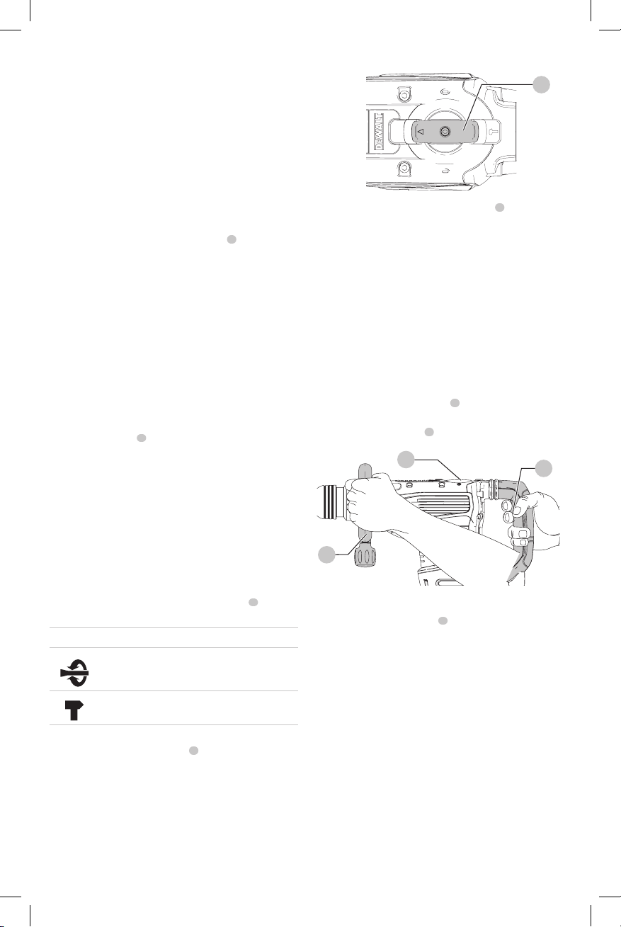
Performing an Application (Fig. F)
WARNING: TO REDUCE THE RISK OF PERSONAL
INJURY, ALWAYS ensure workpiece is anchored or
clampedfirmly.
NOTE: Operating temperature of this tool is 19˚ to 104˚F
(-7˚ to +40˚C). Using the tool outside of this temperature
range will decrease the life of thetool.
1. Insert the appropriate chisel and rotate it by hand to
lock it into the desired position. Refer to Chisel and
ChiselHolder.
2. Using the mode selector dial
4
, selectchipping mode .
Refer to ModeSelection.
3. Adjust the side handle
2
asnecessary.
Fig. F
2
4
1
4. Place the chisel on the desiredlocation.
5. Depress the rocker switch
1
.
6. To stop the hammer, release theswitch.
MAINTENANCE
WARNING: To reduce the risk of serious personal
injury, turn unit off and disconnect it from
power source before making any adjustments or
removing/installing attachments or accessories.
An accidental start-up can causeinjury.
Cleaning
WARNING: Blow dirt and dust out of all air vents with
clean, dry air at least once a week. To minimize the risk
of eye injury, always wear ANSI Z87.1 approved eye
protection when performingthis.
WARNING: Never use solvents or other harsh
chemicals for cleaning the non-metallic parts of
the tool. These chemicals may weaken the plastic
materials used in these parts. Use a cloth dampened
Loading ...
Loading ...
Loading ...