
Loading ...
Loading ...
Loading ...
ENGLISH
5
Bail/Loop Style Auxiliary Handle (Fig. B)
WARNING: To reduce the risk of personal injury,
ALWAYS operate the tool with the bail/loop style
auxiliary handle properly installed. Failure to do so
may result in the bail/loop style auxiliary handle
slipping during tool operation and subsequent
loss of control. Hold tool with both hands to
maximizecontrol.
The bail/loop style auxiliary handle
2
clamps to the front of
the gear case and may be rotated 360˚ to permit right- or
left-hand use.
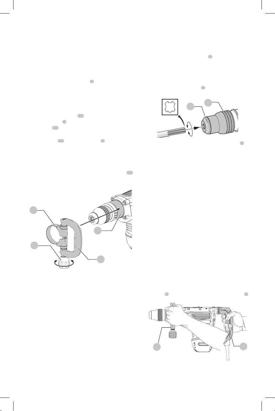
Mounting the Bail/Loop Style Auxiliary
Handle (Fig. B)
1. Widen the ring opening
11
of the bail/loop style
auxiliary handle
2
by rotating the screw for handle
mounting
10
counterclockwise.
2. Slide the assembly onto the nose of the tool, through
the steel ring
11
and onto the collar
3
, past the chisel
holder andsleeve.
3. Rotate the bail/loop style auxiliary handle to the
desiredposition.
4. Lock the bail/loop style auxiliary handle in place by
securely tightening the screw for handle mounting
10
rotating it clockwise so that the assembly will notrotate.
Fig. B
3
2
11
10
Chisels and Chisel Holder
WARNING: Burn Hazard. ALWAYS wear gloves when
changing chisels. Accessible metal parts on the tool
and chisels may get extremely hot during operation.
Small chisels of broken material may damage
barehands.
WARNING: Do not attempt to tighten or loosen drill
chisels (or any other accessory) by gripping the front
part of the chuck and turning the tool on. Damage to
the chuck and personal injury mayoccur.
The chipping hammer can be fitted with various chisels
depending on the desired application. Use sharp
chiselsonly.
Inserting and Removing SDS MAX
Chisels (Fig. C)
NOTE: Accessories and attachments used must be
lubricated around the SDSMAXfitment beforeinstallation.
1. Insert chisel in the chisel holder
6
and apply downward
pressure while rotating to secure the chisel into place.
The chisel shank must beclean.
2. Ensure the chisel is properlyengaged.
NOTE: The chisel needs to move several centimeters in
and out of the chisel holder
6
when properlyengaged.
6
7
Fig. C
3. To remove the chisel pull back the locking sleeve
7
and
pull the chiselout.
Chisel Position Adjustment
Turn the mode selector to chisel adjustment icon (Refer to
Mode Selection) to adjust the chisel to the desired position.
There are multiple positions to set the angle of thechisel.
NOTE: After finding the desired position, slightly
maneuver the chisel back and forth to ensure the chisel is
properlyengaged.
OPERATION
WARNING: To reduce the risk of serious personal
injury, turn unit off and disconnect it from
power source before making any adjustments or
removing/installing attachments or accessories.
An accidental start-up can causeinjury.
Proper Hand Position (Fig. D)
WARNING: To reduce the risk of serious personal injury,
ALWAYS use proper hand position as shown.
WARNING: To reduce the risk of serious personal
injury, ALWAYS hold securely in anticipation of a
suddenreaction.
Proper hand position requires one hand on the mounted
side handle
2
with the other hand on the mainhandle
5
.
Fig. D
2
5
Loading ...
Loading ...
Loading ...