Loading ...
Loading ...
Loading ...
ENGLISH
8
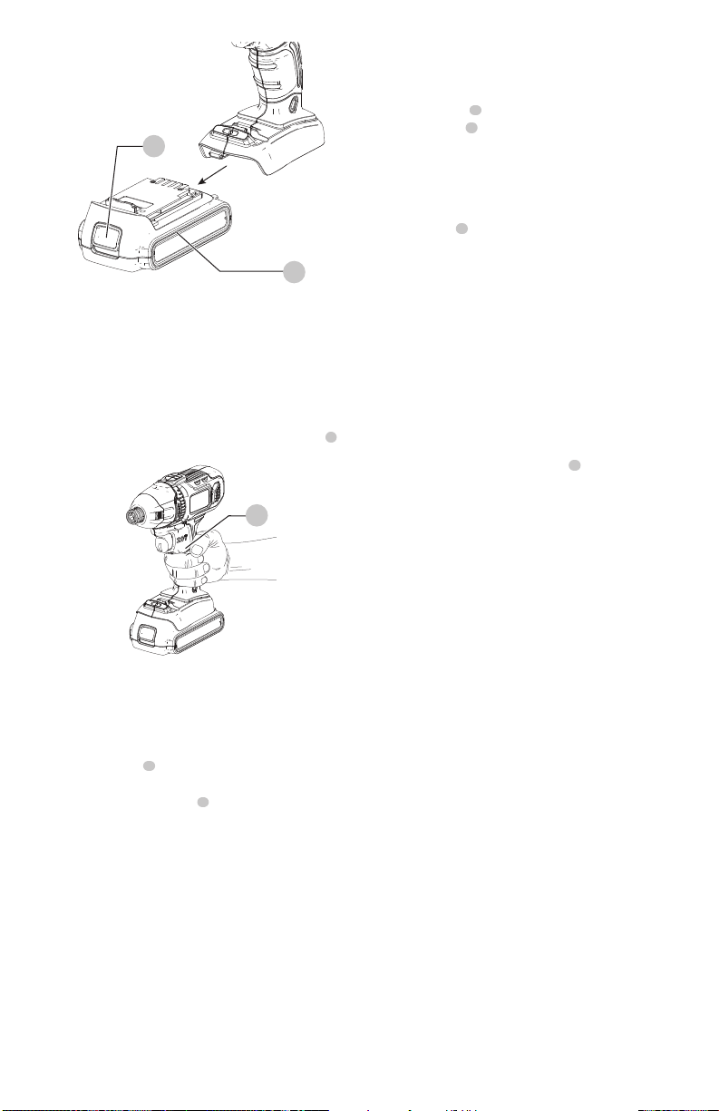
Fig.D
3
Proper Hand Position (Fig. D)
WARNING: To reduce the risk of serious personal
injury, ALWAYS use proper hand position as shown.
WARNING: To reduce the risk of serious personal
injury, ALWAYS hold securely in anticipation of a
suddenreaction.
Proper hand position requires one hand on the main handle
3
.
Variable Speed Trigger and Forward/
Reverse Control Button (Fig. A)
The tool is turned ON and OFF by pulling and releasing the
variable speed trigger
1
. The farther the trigger is pulled,
the higher the speed of the tool.
A forward/reverse control button
2
determines the rotational
direction of the tool and also serves as a lock-offbutton.
• To select forward rotation, release the trigger and
depress the forward/reverse control button on the right
side of the tool.
• To select reverse, depress the forward/reverse control
button on the left side of the tool.
NOTE: The center position of the control button locks the
tool in the off position. When changing the position of the
control button, be sure the trigger is released.
NOTE: Continuous use in variable speed range is not
recommended. It may damage the switch and should
beavoided.
NOTE: The first time the tool is run after changing the
direction of rotation, you may hear a click on start up. This is
normal and does not indicate a problem.
Fig.C
8
9
LED Worklight Fig. A
CAUTION: Do not stare into worklight. Serious eye
injury couldresult.
There is a worklight
6
located on the foot of the drill near
the bit storage slot
7
. The worklight will be activated when
the trigger switch is squeezed.
NOTE: The worklight is for lighting the immediate work
surface and is not intended to be used as a flashlight.
On Board Bit Storage Fig. A
A bit storage slot
7
is built-in to the foot of the drill.
Usage (Fig. A)
WARNING: Use only impact accessories. Non-impact
accessories may break and cause a hazardous
condition. Inspect accessory prior to use to ensure that
it con tains no cracks.
CAUTION: Ensure fastener and/or system will
withstand the level of torque generated by the tool.
Excessive torque may cause breakage and possible
personal injury.
1. Place the accessory on the fastener head. Keep the tool
pointed straight at the fastener.
2. Press variable speed trigger switch
1
to start operation.
Release variable speed trigger switch to stop operation.
Always check torque with a torque wrench, as the
fastening torque is affected by many factors including
the following:
- Voltage: Low voltage, due to a nearly discharged
battery, will reduce fastening torque.
- Accessory size: Failure to use the correct accessory
size will cause a reduction in fasteningtorque.
- Bolt size: Larger bolt diameters generally
require higher fastening torque. Fastening torque
will also vary according to length, grade, and
torquecoefficient.
- Bolt: Ensure that all threads are free of rust and
other debris to allow proper fastening torque.
- Material: The type of material and surface finish of
the material will affect fastening torque.
- Fastening time: Longer fasten ing time results in
increased fastening torque. Using a longer fastening
time than recommended could cause the fasteners
to be overstressed, stripped ordamaged.
MAINTENANCE
WARNING: To reduce the risk of serious personal
injury, turn unit off and remove the battery pack
before making any adjustments or removing/
installing attachments or accessories. An
accidental start-up can causeinjury.
Loading ...
Loading ...
Loading ...