
PJEZ* easy - controlli elettronici per unità statiche/ventilate a normale/bassa temperatura / electronic controller for static/ventilated normal/low temperature units
+050004140 - rel. 1.5 - 03.06.2009
Dimensioni (mm) / Dimensions (mm)
71x29
10
3
33
74
81
36
58
65,29
28.5
Montaggio a pannello / Panel mounting
max 2,5
1
2
3
tipo Pozidriv
Pozidriv type
non eccedere
nel serraggio
do not tighten
excessively
Frontale (con 2 viti ø 2,5x12 mm) / Front (with 2 screws ø 2,5x12 mm)
Da dietro (con 2 staffe posteriori) / Rear (with 2 quick-fi t side brackets)
1
2
PUSH
Fig. 1
Fig. 2
Fig. 3
Descrizione
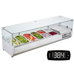
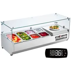
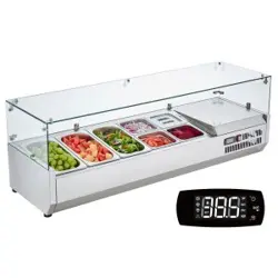
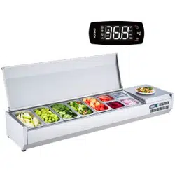
PJEZ* (mod. S, C, M, Y, X) rappresenta una gamma di regolatori elettronici a
microprocessore con visualizzazione a LED realizzati per la gestione di unità frigorifere, vetrine
e banchi frigo.
Modelli disponibili:
PJEZS*, indicati per la gestione di unità frigorifere statiche, prive di ventilatore sull’evapora-•
tore, funzionanti con temperature sopra lo 0°C;
PJEZC*, indicati per la gestione di unità frigorifere ventilate in bassa temperatura. •
PJEZ(Y, X)*, indicati per la gestione di unità frigorifere statiche, prive di ventilatore, •
funzionanti a bassa temperatura;
PJEZM*, soluzione per la semplice misurazione della temperatura.•
Nota: mod. Y= relè collegati elettronicamente all’interno tra loro; mod. X= relè indipendenti.
Caratteristiche tecniche
alimentazione (*) 230 Vac +10 /-15% 50/60 Hz; 115 Vac +10 /-15% 50/60 Hz
12 Vac +10/-15% 50/60 Hz classe 2; 12 Vdc +10/-20% classe 2
potenza nominale 3,5 VA
ingressi (*) sonda NTC o PTC 1 o 3 ingressi.
Ingresso digitale in alternativa a terza sonda
uscite relè (*) relè 2 Hp UL: 12 A Res. 12 FLA 72 LRA - 240 Vac (***),
UL: 12 A Res. 10 FLA 60 LRA - 240 Vac (****)
EN60730-1: 10(10) A 250 Vac (**)
relè 16 A UL: 12 A Res. 5 FLA 30 LRA - 240 Vac C300,
EN60730-1: 12(2) A NO/NC, 10(4) A fi no 60 °C NO,
2(2) A CO - 250 Vac
relè 8 A UL: 8 A Res. 2 FLA 12 LRA - 240 Vac C300,
EN60730-1: 8(4) A NO, 6(4) A NC, 2(2) A CO - 250 Vac
tipo di sonda (*) NTC Std CAREL 10 KΩa 25 °C, PTC Std CAREL 985 Ω a 25 °C
connessioni (*) morsetti fi ssi a vite per cavi con sez. da 0,5 mm
2
a 1,5 mm
2
. Morsetti
estraibili per blocchetti a vite o con contatto a crimpare (sez. cavo fi no a
2,5 mm
2
). Corrente nominale massima per morsetto 12 A.
montaggio (*) per terminale: mediante viti dal frontale o con staffe posteriori
visualizzazione display LED 3 cifre con segno (-199…999) e punto decimale; sei LED
di stato
condizioni di funzionamento -10T50 °C - umidità <90% U.R. non condensante
condizioni di immagazzinamento -20T70 °C - umidità <90% U.R. non condensante
intervallo di rilevazione -50T90 °C (-58T194 °F) - risoluzione 0,1 °C/°F
grado di protezione frontale montaggio a quadro con guarnizione: IP65 tipo 1
contenitore terminale plastico, 81x36x65 mm
classifi cazione secondo la protezione
contro le scosse elettriche
Classe II per incorporamento adeguato
inquinamento ambientale normale
PTI dei materiali di isolamento 250 V
periodo delle sollecitazioni elettriche
delle parti isolanti
lungo
categoria di resistenza al calore
e al fuoco
categoria D (UL94 - V0)
immunità contro le sovratensioni categoria 1
tipo di azione e disconnessione contatti relè 1C
n.ro di cicli di manovra delle opera-
zioni automatiche relè (*)
EN60730-1: 100.000 operazioni
UL: 30.000 operazioni (250 Vac)
classe e struttura del software Classe A
pulizia dello strumento utilizzare esclusivamente detergenti neutri ed acqua.
lunghezza max. cavi seriale: 1 km
sonde: 30 m
relè: 10 m
AVVERTENZA:
Non passare cavi di potenza a meno di 3 cm dalla parte inferiore del dispositivo o dalle sonde;
per le connessioni usare solo cavi di rame.
(*) Le caratteristiche indicate si differenziano a seconda del modello.
(**) T OFF minimo tra due start motore deve essere maggiore di 60 s.
(***) solo per i modelli PJEZ(M,S,X)*
(****) solo per i modelli PJEZ(C, Y)*
AVVERTENZE IMPORTANTI
Il prodotto CAREL è un prodotto avanzato, il cui funzionamento è specifi cato nella documenta-
zione tecnica fornita col prodotto o scaricabile, anche anteriormente all’acquisto, dal sito internet
www.carel.com.
Il cliente (costruttore, progettista o installatore dell’equipaggiamento fi nale) si assume ogni
responsabilità e rischio in relazione alla fase di confi gurazione del prodotto per il raggiungimento
dei risultati previsti in relazione all’installazione e/o equipaggiamento fi nale specifi co.
La mancanza di tale fase di studio, la quale è richiesta/indicata nel manuale d’uso, può generare
malfunzionamenti nei prodotti fi nali di cui CAREL non potrà essere ritenuta responsabile.
Il cliente fi nale deve usare il prodotto solo nelle modalità descritte nella documentazione relativa
al prodotto stesso.
La responsabilità di CAREL in relazione al proprio prodotto è regolata dalle condizioni generali di
contratto CAREL editate nel sito www.carel.com e/o da specifi ci accordi con i clienti.
Tabella parametri
Parametro Min. Max. Def. U.M. M
1
PS PASSWORD
F0 200 22 -
/ PARAMETRI SONDA
/2 Stabilità misura C 1 15 4 -
/4 Selezione sonda/ingresso visualizzata/o (*) F 1 3 1 -
/5 Selezione °C / °F ( 0 = °C; 1 = °F) C 0 1 0 -
/6 Disabilitazione punto decimale C 0 1 0 -
/7 Abilitazione allarme sonda 2 (solo PJEZM) C 0 1 0 -
/C1 Calibrazione sonda F -50,0 50,0 0,0 °C/°F
/C2 Calibrazione sonda 2 (*) F -50,0 50,0 0,0 °C/°F
/C3 Calibrazione sonda 3 (*) F -50,0 50,0 0,0 °C/°F
r PARAMETRI REGOLATORE
St Temperatura di regolazione F r1 r2 4.0 °C/°F
r1 SET minimo consentito all’utente C -50,0 r2 -50,0 °C/°F
r2 SET massimo consentito all’utente C r1 200,0 90,0 °C/°F
r3 Modalità di funzionamento
0= direct+defrost; 1= direct; 2= reverse
C0 2 0 -
-
r4 Variazione automatica set point notturno (*) C -50,0 50,0 3.0 °C/°F
rd Differenziale di regolazione (isteresi) F 0,0 19,0 2,0 °C/°F
c PARAMETRI COMPRESSORE
c0 Rit. partenza comp. e ventola dopo accensione C 0 100 0 min
-
c1 Tempo min. tra accensioni successive comp. C 0 100 0 min
-
c2 Tempo min. di spegnimento del compres. C 0 100 0 min
-
c3 Tempo min. di funzionamento del compres. C 0 100 0 min
-
c4 Sicurezza compressore (duty setting) C 0 100 0 min
-
cc Durata ciclo continuo C 0 15 4 h
-
c6 Tempo esclusione allarme dopo ciclo cont. C 0 15 2 h
-
d PARAMETRI SBRINAMENTO
d0 Tipo di sbrinamento (0= resistenza; 1= gas
caldo; 2= resist. a tempo; 3= gas caldo a tem-
po; 4= resist. termostatato a tempo)
C0 4 0 -
-
dI Intervallo tra due sbrinamenti F 0 199 8 h/min
-
dt Temperatura di fi ne sbrinamento (*) F -50,0 130,0 4,0 °C/°F
-
dP Durata max. o durata effettiva sbrinamento F 1 199 30 min/s
-
d4 Sbrin. all’accensione dello strum. (1= attivato) C 0 1 0 -
-
d5 Ritardo sbrinam. all’accensione o da ing. dig. C 0 199 0 min
-
d6 Blocco visualizzazione temperatura durante lo
sbrinamento (1= bloccata visualizzazione)
C0 1 1 -
-
dd Tempo di gocciolamento dopo lo sbrinam. F 0 15 2 min
-
d8 Tempo di esclusione allarmi dopo lo sbrinam. F 0 15 1 h
-
d9 Priorità sbrinam. sulle protezioni compres.
(0= tempi protezione rispettati; 1= tempi
protezione non rispettati)
C0 1 0 -
-
d/ Visualiz. temp. sonda di sbrinamento (*) F - - - -
-
dc Base dei tempi (solo per lo sbrinamento;
0= h/min ; 1= min/s)
C0 1 0 -
-
A PARAMETRI DI ALLARME
A0 Differenziale allarmi e ventole C -20,0 20,0 2,0 °C/°F
AL Soglia/Scostamento allarme di bassa tempera-
tura (AL= 0; allarme escluso)
F -50,0 250,0 0 °C/°F
AH Soglia/Scostamento allarme di alta temperatu-
ra (AH= 0; allarme escluso)
F -50,0 250,0 0 °C/°F
Ad Ritardo allarme bassa e alta temperatura C 0 199 0 min
A4 Confi gurazione ingresso digitale (*)
0= ingresso non attivo;
1= allarme esterno istant. o ritardato (A7);
2= abilitazione defrost (aperto=disabilit.);
3= inizio defrost su fronte di chiusura;
4= switch tenda o funz. notturno
(aperto= set normale);
5= ON/OFF remoto (aperto= OFF);
6= comando uscita AUX [H1=3]
(aperto = AUX disecc.);
7= comando uscita AUX [H1=3] + FAN
OFF (chiuso) (aperto = AUX eccitato);
8= comando uscita AUX [H1=3] +
FAN-OFF (chiuso) + COMP-OFF
(chiuso); (aperto= AUX eccitato);
9= selezione funzionam. direct/reverse:
r3=0 => aperto= direct + defrost;
chiuso= reverse r3=1/2 => aperto= direct;
chiuso= reverse
10= sonda condensatore;
11= sonda prodotto
C0 11 0 -
A7 Ritardo rilevazione allarme esterno (*) C 0 199 0 min
A8 Abilitazione allarme ‘Ed’: fi ne sbrinamento per
timeout (1= abilitato) (*)
C0 1 0 -
-
Ac Allarme alta temperatura condensatore (*) C -50,0 250,0 70,0 °C/°F
AE Differenziale allarme alta temp. condens. (*) C 0,1 20,0 5,0 °C/°F
Acd Ritardo allarme alta temp. condensatore (*) C 0 250 0 min
F PARAMETRI VENTOLE (**)
F0 Gestione ventole: 0= ventole accese escluso
fasi specifi che; 1= ventole attivate in funzione
del parametro F1 escluso fasi specifi che (**)
C0 1 0 -
-
F1 Temperatura spegnimento ventole (**) F -50,0 130,0 5,0 °C/°F
-
F2 Ventole ferme con compressore fermo (**) C 0 1 1 -
-
F3 Stato ventole durante sbrinamento (**)
0= ventole accese; 1= ventole ferme
C0 1 1 -
-
Fd Fermo post gocciolamento. Attivo per ogni
val. di F0 (**)
F 0 15 1 min
-
H ALTRE PREDISPOSIZIONI
H0 Indirizzo seriale C 0 207 1 -
H1 Confi gurazione uscita AUX
0= nessuna funzione associata all’uscita
1= uscita allarme: norm. eccitato
2= uscita allarme: norm. diseccitato
3= uscita aux legata a ID [A4=6/7/8]
ID aperto= aux eccitato
IDchiuso= aux eccitato
C0 3 0 -
H2 Abilitazione tastiera
0= tastiera disabilitata
1= tastiera abilitata
2= tastiera abilitata tranne ON/OFF
C0 2 1 -
H4 Disabilitazione buzzer
0= buzzer abilitato (ON);
1= buzzer disabilitato (OFF)
C0 1 0 -
H5 Codice identifi cativo chiave da supevisore F 0 199 1 -
EZY Selezione del banco Easy Set a seconda del
modello, vedi manuale. (vedi nota)
C0 4 0 -
-
PARAMETRI RTC
tEn Abilitazione RTC (***) C 0 1 1 -
-
d1d Fascia oraria sbrinamento 1 giorno (***) C 0 11 0 giorni
-
d1h Fascia oraria sbrinamento 1 ora (***) C 0 23 0 h
-
d1m Fascia oraria sbrinamento 1 minuto (***) C 0 59 0 min
-
d2d Fascia oraria sbrinamento 2 giorni (***) C 0 11 0 giorni
-
d2h Fascia oraria sbrinamento 2 ore (***) C 0 23 0 h
-
d2m Fascia oraria sbrinamento 2 minuti (***) C 0 59 0 min
-
d3d Fascia oraria sbrinamento 3 giorni (***) C 0 11 0 giorni
-
d3h Fascia oraria sbrinamento 3 ore (***) C 0 23 0 h
-
d3h Fascia oraria sbrinamento 3 minuti (***) C 0 59 0 min
-
d4d Fascia oraria sbrinamento 4 giorni (***) C 0 11 0 giorni
-
d4h Fascia oraria sbrinamento 4 ore (***) C 0 23 0 h
-
d4m Fascia oraria sbrinamento 4 minute (***) C 0 59 0 min
-
nOd Fascia oraria “night on” giorno (***) C 0 11 0 giorni
-
nOh Fascia oraria “night on” ora (***) C 0 23 0 h
-
nOm Fascia oraria “night on” minuti (***) C 0 59 0 min
-
nFd Fascia oraria “night off” giorno (***) C 0 11 0 giorni
-
nFh Fascia oraria “night off” minuti (***) C 0 23 0 h
-
nFm Fascia oraria “night off” minuti (***) C 0 59 0 min
-
AOd Fascia oraria “aux on” giorno (***) C 0 11 0 giorni
-
AOh Fascia oraria “aux on” ora (***) C 0 23 0 h
-
AOm Fascia oraria “aux on” minuti (***) C 0 59 0 min
-
AFd Fascia oraria “aux off” giorno (***) C 0 11 0 giorni
-
AFh Fascia oraria “aux off” ora (***) C 0 23 0 h
-
AFm Fascia oraria “aux off” minuti (***) C 0 59 0 min
-
dAY RTC giorno della settimana (***) C 1 7 1 giorni
-
hr RTC ora (***) C 0 23 0 h
-
MIn RTC minuto (***) C 0 59 0 min
-
1
presenza parametro del mod. PJEZM*: sì= ; no= -
(*) parametri non presenti nei modelli con una sonda.
(**) parametri non presenti nei modelli PJEZS, PJEZX e PJEZY
(***) parametri non presenti nei modelli privi di RTC
nota: tramite il parametro “Easy Set” è possibile selezionare uno dei 4 set di confi gurazione
rapida memorizzati nello strumento, contenenti al massimo 25 parametri ciascuno.
PJEZ(S, X)*: EZY=1: temperatura normale no defrost
EZY=2: temperatura normale con defrost a tempo
EZY=3: temperatura normale uscita in heating
EZY=4: temperatura normale defrost termostatato (d0=4)
PJEZ(C, Y)* EZY=1: bassa temperatura con defrost a gas caldo
EZY=2: bassa temperatura variazione automatica set notturno da ingresso digitale
EZY=3: bassa temperatura con gestione allarme ingresso digitale
EZY=4: bassa temperatura sbrinamento termostatato (d0=4).
PJEZ(S, X)*
PJEZ(C, Y)*
1 2 3 4 5 6 7
9 10 118
L
N
L N
DEF. T.
DI / PROBE
AMB. T.
NTC/PTC
PROBES
or
SERIAL
CONV
PROG.
KEY
-10T50
1 2 3 4 5 6 7
9 10 118
L
N
L N
230Vac or
115 Vac or
12 Vac/Vdc
230Vac or
115 Vac or
12 Vac/Vdc
DEF. T.
DI / PROBE
AMB. T.
NTC/PTC
PROBES
or
or
SERIAL
CONV
PROG.
KEY
-10T50
AUX
or
AUX
PJEZ(M)*
1 2 3 4 5 6 7
9 10 118
L
N
L N
230Vac or
115 Vac or
12 Vac/Vdc
DEF. T.
DI / PROBE
AMB. T.
NTC/PTC
PROBES
or
SERIAL
CONV
PROG.
KEY
-10T50
AUX
Collegamenti elettrici / Electrical connections
Fig. 4
Tabella allarmi
Codice
allarme
buzzer e relè
allarme
LED Descrizione allarme Parametri
coinvolti
E0 attivi ON errore sonda 1= regolazione -
E1 non attivi ON errore sonda 2= defrost [d0 = 0 / 1]
E2 non attivi ON errore sonda 3= condensatore [A4=10]
IA attivi ON allarme esterno [A4 = 1] [+A7]
dOr attivi ON allarme porta aperta [A4 = 7/8][+A7]
LO attivi ON allarme bassa temperatura [AL] [Ad]
HI attivi ON allarme alta temperatura [AH] [Ad]
EE non attivi ON errore parametri macchina -
EF non attivi ON errore parametri funzionamento -
Ed non attivi ON defrost fi nito per timeout [dP] [dt] [d4] [A8]
dF non attivi OFF defrost in esecuzione [d6=0]
cht non attivi ON pre-allarme condensatore sporco [A4=10]
CHt attivi ON allarme condensatore sporco [A4=10]
EtC non attivi ON allarme orologio se fasce attive
serial conv. IROPZ485S0
prog. key IROPZKEY* or PSOPZKEY*
12 Vac/Vdc transformers: TRA12UNI11 or TRA12VDE00
Smaltimento del prodotto
L’apparecchiatura (o il prodotto) deve essere oggetto di raccolta separata in
conformità alle vigenti normative locali in materia di smaltimento
Disposal of the product
The appliance (or the product) must be disposed of separately in accordan-
ce with the local waste disposal legislation in force.
Table of alarms
Alarm
code
buzzer and
alarm relay
LED Description Parameters
involved
E0 active ON probe 1 error= control -
E1 inactive ON probe 2 error= defrost [d0 = 0 / 1]
E2 inactive ON probe 3 error= condenser [A4=10]
IA active ON external alarm [A4 = 1] [+A7]
dOr active ON open door alarm [A4 = 7/8][+A7]
LO active ON low temperature alarm [AL] [Ad]
HI active ON high temperature alarm [AH] [Ad]
EE inactive ON unit parameter error -
EF inactive ON operating parameter error -
Ed inactive ON defrost ended by timeout [dP] [dt] [d4] [A8]
dF inactive OFF defrost running [d6=0]
cht inactive ON condenser dirty pre-alarm [A4=10]
CHt active ON condenser dirty alarm [A4=10]
EtC inactive ON clock alarm if bands active
Description
PJEZ* (models S, C, Y and X) represent a range of electronic microprocessor
controllers with LED display developed for the management of refrigerating units, display
cabinets and showcases.
Models available:
PJEZS*, designed for the management of static refrigerating units, no fan on the evapora-•
tor, operating at temperatures above 0°C;
PJEZC*, designed for the management of low temperature ventilated refrigerating units. •
PJEZ(Y, X)*, designed for the management of static refrigerating units, no fan, operating •
at low temperatures;
PJEZM*, simple solution for measuring the temperature.•
Note: model Y= relays connected electronically internally; model X= independent relays.
Technical specifi cations
power supply (*) 230 Vac +10 /-15% 50/60 Hz; 115 Vac +10 /-15% 50/60 Hz
12 Vac +10/-15% 50/60 Hz class 2; 12 Vdc +10/-20% class 2;
rated power 3,5 VA
inputs (*) NTC or PTC probes 1 or 3 inputs.
Digital input as alternative to third probe
relay outputs (*) 2 HP relay UL: 12 A Res. 12 FLA 72 LRA - 240 Vac (***),
UL: 12 A Res. 10 FLA 60 LRA - 240 Vac (****)
EN60730-1: 10(10) A 250 Vac (**)
16 A relay UL: 12 A Res. 5 FLA 30 LRA - 240 Vac C300,
EN60730-1: 12(2) A NO/NC, 10(4) A up to 60 °C NO,
2(2) A CO - 250 Vac
8 A relay UL: 8 A Res. 2 FLA 12 LRA - 240 Vac C300,
EN60730-1: 8(4) A NO, 6(4) A NC, 2(2) A CO - 250 Vac
type of probe (*) Std CAREL NTC 10 KΩ at 25 °C, Std CAREL PTC 985 Ω at 25 °C
connections (*) screw terminals for cables with cross-sect. from 0.5 mm
2
to 1.5 mm
2
.
Plug-in terminals for screw blocks or with crimped contact (cable cross-
sect. up to 2.5 mm
2
). Rated maximum current per terminal 12 A.
assembly (*) terminal: using screws from the front panel or with rear brackets. Interfa-
ce: wall mounting, 4 screws, spacing 101x151 mm
display 3 digit LED display with sign (-199 to 999) and decimal point; six
status LEDs
operating conditions -10T50 °C - humidity <90% rH non-condensing
storage conditions -20T70 °C - humidity <90% rH non-condensing
range of measurement -50T90 °C (-58T194 °F) - resolution 0.1 °C/°F
front panel index of protection panel installation with IP65 type 1 gasket
case plastic terminal, 81x36x65 mm
classifi cation according to protec-
tion against electric shock
Class II when suitably integrated
environmental pollution normal
PTI of the insulating material 250 V
period of stress across the insu-
lating parts
long
category of resistance to heat
and fi re
category D (UL94 - V0)
immunity against voltage surges category 1
type of action and disconnection 1C relay contacts
no. of relay automatic operating
cycles (*)
EN60730-1: 100,000 operations
UL: 30,000 operations (250 Vac)
software class and structure Class A
cleaning the instrument Only use neutral detergents and water.
cable max. lenght serial: 1 km
probes: 30 m
relay: 10 m
WARNING:
do not run the power cable less than 3 cm from the bottom part of the device or from the
probes; for the connections only use copper wires.
(*) The features indicated differ according to the model.
(**) T OFF minimum time between two starts of the motor must be greater than 60 s.
(***) only for PJEZ(M,S,X)*
(****) only for PJEZ(C, Y)*
IMPORTANT WARNINGS
The CAREL product is a state-of-the-art device, whose operation is specifi ed in the technical
documentation supplied with the product or can be downloaded, even prior to purchase, from
the website www.carel.com.
The customer (manufacturer, developer or installer of the fi nal equipment) accepts all liability
and risk relating to the confi guration of the product in order to reach the expected results in
relation to the specifi c fi nal installation and/or equipment. The failure to complete such phase,
which is required/indicated in the user manual, may cause the fi nal product to malfunction;
CAREL accepts no liability in such cases. The customer must use the product only in the manner
described in the documentation relating to the product. The liability of CAREL in relation to its
products is specifi ed in the CAREL general contract conditions, available on the website www.
carel.com and/or by specifi c agreements with customers.
Table of parameters
Parameter Min. Max. Def. UOM M
1
PS PASSWORD
F0 200 22 -
/ PROBE PARAMETERS
/2 Measurement stability C 1 15 4 -
/4 Select probe/input displayed (*) F 1 3 1 -
/5 Select °C / °F ( 0 = °C; 1 = °F) C 0 1 0 -
/6 Disable decimal point C 0 1 0 -
/7 Enable probe 2 alarm (PJEZM only) C 0 1 0 -
/C1 Probe calibration F -50.0 50.0 0.0 °C/°F
/C2 Probe 2 calibration (*) F -50.0 50.0 0.0 °C/°F
/C3 Probe 3 calibration F -50.0 50.0 0.0 °C/°F
r CONTROL PARAMETERS
St Control temperature F r1 r2 4.0 °C/°F
r1 Minimum set point allowed to the user C -50.0 r2 -50.0 °C/°F
r2 Maximum set point allowed to the user C r1 200.0 90.0 °C/°F
r3 Operating mode
0= direct+defrost; 1= direct; 2= reverse
C0 2 0 -
-
r4 Automatic night-time set point variation C -50.0 50.0 3.0 °C/°F
rd Control differential (hysteresis) F 0.0 19.0 2.0 °C/°F
c COMPRESSOR PARAMETERS
c0 Comp. and fan start delay after start-up C 0 100 0 min
-
c1 Min. time between successive comp. starts C 0 100 0 min
-
c2 Min. compressor off time C 0 100 0 min
-
c3 Min. compressor on time C 0 100 0 min
-
c4 Compressor safety (duty setting) C 0 100 0 min
-
cc Continuous cycle duration C 0 15 4 h
-
c6 Alarm bypass time after cont. cycle C 0 15 2 h
-
d DEFROST PARAMETERS
d0 Type of defrost (0= heater; 1= hot gas; 2=
heater by time; 3= hot gas by time; 4= heater
by time with temp. cont.)
C0 4 0 -
-
dI Interval between two defrosts F 0 199 8 h/min
-
dt End defrost temperature F 50.0 130.0 4.0 °C/°F
-
dP Max. or effective defrost duration F 1 199 30 min/s
-
d4 Defrost when the instrument is switched on
(1= activated)
C0 1 0 -
-
d5 Defrost delay on start-up or from digital input C 0 199 0 min
-
d6 Disable temperature display during defrost (1=
display disabled)
C0 1 1 -
-
dd Dripping time after defrost F 0 15 2 min
-
d8 Alarm bypass time after defrost F 0 15 1 h
-
d9 Defrost priority over comp. protectors (0=
protection time respected; 1= protection time
not respected)
C0 1 0 -
-
d/ Display defrost probe temp. F - - - -
-
dc Time base (for defrost only; 0= h/min; 1= min/s) C 0 1 0 -
-
A ALARM PARAMETERS
A0 Alarm and fan differential C -20.0 20.0 2.0 °C/°F
AL Low temperature alarm threshold/deviation
(AL= 0; alarm disabled)
F -50.0 250.0 0 °C/°F
AH High temperature alarm threshold/deviation
(AH= 0; alarm disabled)
F 50.0 250.0 0 °C/°F
Ad Low and high temperature alarm delay C 0 199 0 min
A4 Digital input confi guration
0= input not active;
1= exter. alarm, instant (A7= 0) or delayed (A7>0);
2= enable defrost (open=disabled);
3= start defrost on closing;
4= curtain switch or night-time operation
(open= normal setpoint);
5= remote ON/OFF (open= OFF);
6= AUX output control [H1=3] (open =
AUX de-energ.);
7= AUX output [H1=3] + FAN OFF control
(closed) (open = AUX energised);
8= AUX output [H1=3] + FAN-OFF
(closed) + COMP-OFF control (closed);
(open= AUX energised);
9= select direct/reverse operation:
r3=0 => open= direct + defrost;
closed= reverse r3=1/2 => open= direct;
closed= reverse
10= condenser probe;
11= product probe
C0 11 0 -
A7 External alarm detection delay C 0 199 0 min
A8 Enable alarm ‘Ed’: end defrost by timeout
(1= enabled)
C0 1 0 -
-
Ac High condenser temperature alarm C -50.0 250.0 70.0 °C/°F
AE High condenser temperature alarm differential C 0.1 20.0 5.0 °C/°F
Acd High condenser temperature alarm delay C 0 250 0 min
F FAN PARAMETERS (**)
F0 Fan management: 0= fans on excluding specifi c
phases; 1= fans on according to parameter F1
excluding specifi c phases (**)
C0 1 0 -
-
F1 Fans shutdown temperature (**) F 50.0 130.0 5.0 °C/°F
-
F2 Fans off when compressor off (**) C 0 1 1 -
-
F3 Fans status during defrost (**)
0= fan ON; 1= fan OFF
C0 1 1 -
-
Fd Off for post-dripping. Active for each val. of F0 (**) F 0 15 1 min
-
H OTHER SETTINGS
H0 Serial address C 0 207 1 -
H1 AUX output confi guration
0= no function associated with the output
1= alarm output usually energised
2= alarm output usually de-energised
3= auxiliary output driven by dig. input
[A4=6/7/8]
dig. input OPEN= AUX de-energised
dig. input CLOSED= AUX energised
C0 3 0 -
H2 Enable keypad
0= keypad disabled
1= keypad enabled
2= keypad enabled except for ON/OFF function
C0 2 1 -
H4 Disable buzzer
0= buzzer enabled
1= buzzer disabled
C0 1 0 -
H5 Key ID code from supervisor F 199 1 -
EZY Select Easy Set according to the model, see
manual (see notes)
C0 4 0 -
-
RTC PARAMETERS
tEn Disable RTC C 0 1 1 -
-
d1d Defrost time band 1 day C 0 11 0 days
-
d1h Defrost time band 1 hours C 0 23 0 h
-
d1m Defrost time band 1 minutes C 0 59 0 min
-
d2d Defrost time band 2 day C 0 11 0 days
-
d2h Defrost time band 2 hours C 0 23 0 h
-
d2m Defrost time band 2 minutes C 0 59 0 min
-
d3d Defrost time band 3 day C 0 11 0 days
-
d3h Defrost time band 3 hours C 0 23 0 h
-
d3h Defrost time band 3 minutes C 0 59 0 min
-
d4d Defrost time band 4 day C 0 11 0 days
-
d4h Defrost time band 4 hours C 0 23 0 h
-
d4m Defrost time band 4 minute C 0 59 0 min
-
nOd "Night on" time band day C 0 11 0 days
-
nOh "Night on" time band hours C 0 23 0 h
-
nOm "Night on" time band minutes C 0 59 0 min
-
nFd "Night off" time band day C 0 11 0 days
-
nFh "Night off" time band hours C 0 23 0 h
-
nFm "Night off" time band minutes C 0 59 0 min
-
AOd "Aux on" time band day C 0 11 0 days
-
AOh "Aux on" time band hours C 0 23 0 h
-
AOm "Aux on" time band minutes C 0 59 0 min
-
AFd "Aux off" time band day C 0 11 0 days
-
AFh "Aux off" time band hours C 0 23 0 h
-
AFm "Aux off" time band minutes C 0 59 0 min
-
dAY RTC day of the week C 1 7 1 days
-
hr RTC hours C 0 23 0 h
-
MIn RTC minutes C 0 59 0 min
-
1
parameter available on model PJEZM*: yes= ; no= -
(*) parameters not available in PJEZS models with one probe.
(**) parameters not available in PJEZS models
(***) parameters not available on models without RTC
note: the “Easy Set” parameter is used to select one of 4 sets of quick confi gurations stored in
the instrument, each containing a maximum of 25 parameters.
PJEZ(S, X)*: EZY=1: normal temperature, no defrost
EZY=2: normal temperature with timed defrost
EZY=3: normal temperature, heating output
EZY=4: normal temperature, defrost controlled by temperature (d0=4)
PJEZ(C, Y)*: EZY=1: low temperature with hot gas defrost
EZY=2: low temp. with automatic night-time set point variation via digital input
EZY=3: low temperature with management of alarm via digital input
EZY=4: low temperature, defrost controlled by temperature (d0=4).
WARNING: separate as much as possible the probe and digital input signal
cables from the cables carrying inductive loads and power cables to avoid
possible electromagnetic disturbance. Never run power cables (including
the electrical panel wiring) and signal cables in the same conduits.
NO POWER
& SIGNAL
CABLES
TOGETHER
READ CAREFULLY IN THE TEXT!
NO POWER
& SIGNAL
CABLES
TOGETHER
READ CAREFULLY IN THE TEXT!
Attenzione: separare quanto più possibile i cavi delle sonde e degli ingressi
digitali dai cavi dei carichi induttivi e di potenza per evitare possibili disturbi
elettromagnetici. Non inserire mai nelle stesse canaline (comprese quelle
dei quadri elettrici) cavi di potenza e cavi di segnale.
NO POWER
& SIGNAL
CABLES
TOGETHER
READ CAREFULLY IN THE TEXT!

PJEZ* easy - controlli elettronici per unità statiche/ventilate a normale/bassa temperatura / electronic controller for static/ventilated normal/low temperature units
+050004140 - rel. 1.5 - 03.06.2009
Dimensioni (mm) / Dimensions (mm)
71x29
10
3
33
74
81
36
58
65,29
28.5
Montaggio a pannello / Panel mounting
max 2,5
1
2
3
tipo Pozidriv
Pozidriv type
non eccedere
nel serraggio
do not tighten
excessively
Frontale (con 2 viti ø 2,5x12 mm) / Front (with 2 screws ø 2,5x12 mm)
Da dietro (con 2 staffe posteriori) / Rear (with 2 quick-fi t side brackets)
1
2
PUSH
Fig. 1
Fig. 2
Fig. 3
Descrizione
PJEZ* (mod. S, C, M, Y, X) rappresenta una gamma di regolatori elettronici a
microprocessore con visualizzazione a LED realizzati per la gestione di unità frigorifere, vetrine
e banchi frigo.
Modelli disponibili:
PJEZS*, indicati per la gestione di unità frigorifere statiche, prive di ventilatore sull’evapora-•
tore, funzionanti con temperature sopra lo 0°C;
PJEZC*, indicati per la gestione di unità frigorifere ventilate in bassa temperatura. •
PJEZ(Y, X)*, indicati per la gestione di unità frigorifere statiche, prive di ventilatore, •
funzionanti a bassa temperatura;
PJEZM*, soluzione per la semplice misurazione della temperatura.•
Nota: mod. Y= relè collegati elettronicamente all’interno tra loro; mod. X= relè indipendenti.
Caratteristiche tecniche
alimentazione (*) 230 Vac +10 /-15% 50/60 Hz; 115 Vac +10 /-15% 50/60 Hz
12 Vac +10/-15% 50/60 Hz classe 2; 12 Vdc +10/-20% classe 2
potenza nominale 3,5 VA
ingressi (*) sonda NTC o PTC 1 o 3 ingressi.
Ingresso digitale in alternativa a terza sonda
uscite relè (*) relè 2 Hp UL: 12 A Res. 12 FLA 72 LRA - 240 Vac (***),
UL: 12 A Res. 10 FLA 60 LRA - 240 Vac (****)
EN60730-1: 10(10) A 250 Vac (**)
relè 16 A UL: 12 A Res. 5 FLA 30 LRA - 240 Vac C300,
EN60730-1: 12(2) A NO/NC, 10(4) A fi no 60 °C NO,
2(2) A CO - 250 Vac
relè 8 A UL: 8 A Res. 2 FLA 12 LRA - 240 Vac C300,
EN60730-1: 8(4) A NO, 6(4) A NC, 2(2) A CO - 250 Vac
tipo di sonda (*) NTC Std CAREL 10 KΩa 25 °C, PTC Std CAREL 985 Ω a 25 °C
connessioni (*) morsetti fi ssi a vite per cavi con sez. da 0,5 mm
2
a 1,5 mm
2
. Morsetti
estraibili per blocchetti a vite o con contatto a crimpare (sez. cavo fi no a
2,5 mm
2
). Corrente nominale massima per morsetto 12 A.
montaggio (*) per terminale: mediante viti dal frontale o con staffe posteriori
visualizzazione display LED 3 cifre con segno (-199…999) e punto decimale; sei LED
di stato
condizioni di funzionamento -10T50 °C - umidità <90% U.R. non condensante
condizioni di immagazzinamento -20T70 °C - umidità <90% U.R. non condensante
intervallo di rilevazione -50T90 °C (-58T194 °F) - risoluzione 0,1 °C/°F
grado di protezione frontale montaggio a quadro con guarnizione: IP65 tipo 1
contenitore terminale plastico, 81x36x65 mm
classifi cazione secondo la protezione
contro le scosse elettriche
Classe II per incorporamento adeguato
inquinamento ambientale normale
PTI dei materiali di isolamento 250 V
periodo delle sollecitazioni elettriche
delle parti isolanti
lungo
categoria di resistenza al calore
e al fuoco
categoria D (UL94 - V0)
immunità contro le sovratensioni categoria 1
tipo di azione e disconnessione contatti relè 1C
n.ro di cicli di manovra delle opera-
zioni automatiche relè (*)
EN60730-1: 100.000 operazioni
UL: 30.000 operazioni (250 Vac)
classe e struttura del software Classe A
pulizia dello strumento utilizzare esclusivamente detergenti neutri ed acqua.
lunghezza max. cavi seriale: 1 km
sonde: 30 m
relè: 10 m
AVVERTENZA:
Non passare cavi di potenza a meno di 3 cm dalla parte inferiore del dispositivo o dalle sonde;
per le connessioni usare solo cavi di rame.
(*) Le caratteristiche indicate si differenziano a seconda del modello.
(**) T OFF minimo tra due start motore deve essere maggiore di 60 s.
(***) solo per i modelli PJEZ(M,S,X)*
(****) solo per i modelli PJEZ(C, Y)*
AVVERTENZE IMPORTANTI
Il prodotto CAREL è un prodotto avanzato, il cui funzionamento è specifi cato nella documenta-
zione tecnica fornita col prodotto o scaricabile, anche anteriormente all’acquisto, dal sito internet
www.carel.com.
Il cliente (costruttore, progettista o installatore dell’equipaggiamento fi nale) si assume ogni
responsabilità e rischio in relazione alla fase di confi gurazione del prodotto per il raggiungimento
dei risultati previsti in relazione all’installazione e/o equipaggiamento fi nale specifi co.
La mancanza di tale fase di studio, la quale è richiesta/indicata nel manuale d’uso, può generare
malfunzionamenti nei prodotti fi nali di cui CAREL non potrà essere ritenuta responsabile.
Il cliente fi nale deve usare il prodotto solo nelle modalità descritte nella documentazione relativa
al prodotto stesso.
La responsabilità di CAREL in relazione al proprio prodotto è regolata dalle condizioni generali di
contratto CAREL editate nel sito www.carel.com e/o da specifi ci accordi con i clienti.
Tabella parametri
Parametro Min. Max. Def. U.M. M
1
PS PASSWORD
F0 200 22 -
/ PARAMETRI SONDA
/2 Stabilità misura C 1 15 4 -
/4 Selezione sonda/ingresso visualizzata/o (*) F 1 3 1 -
/5 Selezione °C / °F ( 0 = °C; 1 = °F) C 0 1 0 -
/6 Disabilitazione punto decimale C 0 1 0 -
/7 Abilitazione allarme sonda 2 (solo PJEZM) C 0 1 0 -
/C1 Calibrazione sonda F -50,0 50,0 0,0 °C/°F
/C2 Calibrazione sonda 2 (*) F -50,0 50,0 0,0 °C/°F
/C3 Calibrazione sonda 3 (*) F -50,0 50,0 0,0 °C/°F
r PARAMETRI REGOLATORE
St Temperatura di regolazione F r1 r2 4.0 °C/°F
r1 SET minimo consentito all’utente C -50,0 r2 -50,0 °C/°F
r2 SET massimo consentito all’utente C r1 200,0 90,0 °C/°F
r3 Modalità di funzionamento
0= direct+defrost; 1= direct; 2= reverse
C0 2 0 -
-
r4 Variazione automatica set point notturno (*) C -50,0 50,0 3.0 °C/°F
rd Differenziale di regolazione (isteresi) F 0,0 19,0 2,0 °C/°F
c PARAMETRI COMPRESSORE
c0 Rit. partenza comp. e ventola dopo accensione C 0 100 0 min
-
c1 Tempo min. tra accensioni successive comp. C 0 100 0 min
-
c2 Tempo min. di spegnimento del compres. C 0 100 0 min
-
c3 Tempo min. di funzionamento del compres. C 0 100 0 min
-
c4 Sicurezza compressore (duty setting) C 0 100 0 min
-
cc Durata ciclo continuo C 0 15 4 h
-
c6 Tempo esclusione allarme dopo ciclo cont. C 0 15 2 h
-
d PARAMETRI SBRINAMENTO
d0 Tipo di sbrinamento (0= resistenza; 1= gas
caldo; 2= resist. a tempo; 3= gas caldo a tem-
po; 4= resist. termostatato a tempo)
C0 4 0 -
-
dI Intervallo tra due sbrinamenti F 0 199 8 h/min
-
dt Temperatura di fi ne sbrinamento (*) F -50,0 130,0 4,0 °C/°F
-
dP Durata max. o durata effettiva sbrinamento F 1 199 30 min/s
-
d4 Sbrin. all’accensione dello strum. (1= attivato) C 0 1 0 -
-
d5 Ritardo sbrinam. all’accensione o da ing. dig. C 0 199 0 min
-
d6 Blocco visualizzazione temperatura durante lo
sbrinamento (1= bloccata visualizzazione)
C0 1 1 -
-
dd Tempo di gocciolamento dopo lo sbrinam. F 0 15 2 min
-
d8 Tempo di esclusione allarmi dopo lo sbrinam. F 0 15 1 h
-
d9 Priorità sbrinam. sulle protezioni compres.
(0= tempi protezione rispettati; 1= tempi
protezione non rispettati)
C0 1 0 -
-
d/ Visualiz. temp. sonda di sbrinamento (*) F - - - -
-
dc Base dei tempi (solo per lo sbrinamento;
0= h/min ; 1= min/s)
C0 1 0 -
-
A PARAMETRI DI ALLARME
A0 Differenziale allarmi e ventole C -20,0 20,0 2,0 °C/°F
AL Soglia/Scostamento allarme di bassa tempera-
tura (AL= 0; allarme escluso)
F -50,0 250,0 0 °C/°F
AH Soglia/Scostamento allarme di alta temperatu-
ra (AH= 0; allarme escluso)
F -50,0 250,0 0 °C/°F
Ad Ritardo allarme bassa e alta temperatura C 0 199 0 min
A4 Confi gurazione ingresso digitale (*)
0= ingresso non attivo;
1= allarme esterno istant. o ritardato (A7);
2= abilitazione defrost (aperto=disabilit.);
3= inizio defrost su fronte di chiusura;
4= switch tenda o funz. notturno
(aperto= set normale);
5= ON/OFF remoto (aperto= OFF);
6= comando uscita AUX [H1=3]
(aperto = AUX disecc.);
7= comando uscita AUX [H1=3] + FAN
OFF (chiuso) (aperto = AUX eccitato);
8= comando uscita AUX [H1=3] +
FAN-OFF (chiuso) + COMP-OFF
(chiuso); (aperto= AUX eccitato);
9= selezione funzionam. direct/reverse:
r3=0 => aperto= direct + defrost;
chiuso= reverse r3=1/2 => aperto= direct;
chiuso= reverse
10= sonda condensatore;
11= sonda prodotto
C0 11 0 -
A7 Ritardo rilevazione allarme esterno (*) C 0 199 0 min
A8 Abilitazione allarme ‘Ed’: fi ne sbrinamento per
timeout (1= abilitato) (*)
C0 1 0 -
-
Ac Allarme alta temperatura condensatore (*) C -50,0 250,0 70,0 °C/°F
AE Differenziale allarme alta temp. condens. (*) C 0,1 20,0 5,0 °C/°F
Acd Ritardo allarme alta temp. condensatore (*) C 0 250 0 min
F PARAMETRI VENTOLE (**)
F0 Gestione ventole: 0= ventole accese escluso
fasi specifi che; 1= ventole attivate in funzione
del parametro F1 escluso fasi specifi che (**)
C0 1 0 -
-
F1 Temperatura spegnimento ventole (**) F -50,0 130,0 5,0 °C/°F
-
F2 Ventole ferme con compressore fermo (**) C 0 1 1 -
-
F3 Stato ventole durante sbrinamento (**)
0= ventole accese; 1= ventole ferme
C0 1 1 -
-
Fd Fermo post gocciolamento. Attivo per ogni
val. di F0 (**)
F 0 15 1 min
-
H ALTRE PREDISPOSIZIONI
H0 Indirizzo seriale C 0 207 1 -
H1 Confi gurazione uscita AUX
0= nessuna funzione associata all’uscita
1= uscita allarme: norm. eccitato
2= uscita allarme: norm. diseccitato
3= uscita aux legata a ID [A4=6/7/8]
ID aperto= aux eccitato
IDchiuso= aux eccitato
C0 3 0 -
H2 Abilitazione tastiera
0= tastiera disabilitata
1= tastiera abilitata
2= tastiera abilitata tranne ON/OFF
C0 2 1 -
H4 Disabilitazione buzzer
0= buzzer abilitato (ON);
1= buzzer disabilitato (OFF)
C0 1 0 -
H5 Codice identifi cativo chiave da supevisore F 0 199 1 -
EZY Selezione del banco Easy Set a seconda del
modello, vedi manuale. (vedi nota)
C0 4 0 -
-
PARAMETRI RTC
tEn Abilitazione RTC (***) C 0 1 1 -
-
d1d Fascia oraria sbrinamento 1 giorno (***) C 0 11 0 giorni
-
d1h Fascia oraria sbrinamento 1 ora (***) C 0 23 0 h
-
d1m Fascia oraria sbrinamento 1 minuto (***) C 0 59 0 min
-
d2d Fascia oraria sbrinamento 2 giorni (***) C 0 11 0 giorni
-
d2h Fascia oraria sbrinamento 2 ore (***) C 0 23 0 h
-
d2m Fascia oraria sbrinamento 2 minuti (***) C 0 59 0 min
-
d3d Fascia oraria sbrinamento 3 giorni (***) C 0 11 0 giorni
-
d3h Fascia oraria sbrinamento 3 ore (***) C 0 23 0 h
-
d3h Fascia oraria sbrinamento 3 minuti (***) C 0 59 0 min
-
d4d Fascia oraria sbrinamento 4 giorni (***) C 0 11 0 giorni
-
d4h Fascia oraria sbrinamento 4 ore (***) C 0 23 0 h
-
d4m Fascia oraria sbrinamento 4 minute (***) C 0 59 0 min
-
nOd Fascia oraria “night on” giorno (***) C 0 11 0 giorni
-
nOh Fascia oraria “night on” ora (***) C 0 23 0 h
-
nOm Fascia oraria “night on” minuti (***) C 0 59 0 min
-
nFd Fascia oraria “night off” giorno (***) C 0 11 0 giorni
-
nFh Fascia oraria “night off” minuti (***) C 0 23 0 h
-
nFm Fascia oraria “night off” minuti (***) C 0 59 0 min
-
AOd Fascia oraria “aux on” giorno (***) C 0 11 0 giorni
-
AOh Fascia oraria “aux on” ora (***) C 0 23 0 h
-
AOm Fascia oraria “aux on” minuti (***) C 0 59 0 min
-
AFd Fascia oraria “aux off” giorno (***) C 0 11 0 giorni
-
AFh Fascia oraria “aux off” ora (***) C 0 23 0 h
-
AFm Fascia oraria “aux off” minuti (***) C 0 59 0 min
-
dAY RTC giorno della settimana (***) C 1 7 1 giorni
-
hr RTC ora (***) C 0 23 0 h
-
MIn RTC minuto (***) C 0 59 0 min
-
1
presenza parametro del mod. PJEZM*: sì= ; no= -
(*) parametri non presenti nei modelli con una sonda.
(**) parametri non presenti nei modelli PJEZS, PJEZX e PJEZY
(***) parametri non presenti nei modelli privi di RTC
nota: tramite il parametro “Easy Set” è possibile selezionare uno dei 4 set di confi gurazione
rapida memorizzati nello strumento, contenenti al massimo 25 parametri ciascuno.
PJEZ(S, X)*: EZY=1: temperatura normale no defrost
EZY=2: temperatura normale con defrost a tempo
EZY=3: temperatura normale uscita in heating
EZY=4: temperatura normale defrost termostatato (d0=4)
PJEZ(C, Y)* EZY=1: bassa temperatura con defrost a gas caldo
EZY=2: bassa temperatura variazione automatica set notturno da ingresso digitale
EZY=3: bassa temperatura con gestione allarme ingresso digitale
EZY=4: bassa temperatura sbrinamento termostatato (d0=4).
PJEZ(S, X)*
PJEZ(C, Y)*
1 2 3 4 5 6 7
9 10 118
L
N
L N
DEF. T.
DI / PROBE
AMB. T.
NTC/PTC
PROBES
or
SERIAL
CONV
PROG.
KEY
-10T50
1 2 3 4 5 6 7
9 10 118
L
N
L N
230Vac or
115 Vac or
12 Vac/Vdc
230Vac or
115 Vac or
12 Vac/Vdc
DEF. T.
DI / PROBE
AMB. T.
NTC/PTC
PROBES
or
or
SERIAL
CONV
PROG.
KEY
-10T50
AUX
or
AUX
PJEZ(M)*
1 2 3 4 5 6 7
9 10 118
L
N
L N
230Vac or
115 Vac or
12 Vac/Vdc
DEF. T.
DI / PROBE
AMB. T.
NTC/PTC
PROBES
or
SERIAL
CONV
PROG.
KEY
-10T50
AUX
Collegamenti elettrici / Electrical connections
Fig. 4
Tabella allarmi
Codice
allarme
buzzer e relè
allarme
LED Descrizione allarme Parametri
coinvolti
E0 attivi ON errore sonda 1= regolazione -
E1 non attivi ON errore sonda 2= defrost [d0 = 0 / 1]
E2 non attivi ON errore sonda 3= condensatore [A4=10]
IA attivi ON allarme esterno [A4 = 1] [+A7]
dOr attivi ON allarme porta aperta [A4 = 7/8][+A7]
LO attivi ON allarme bassa temperatura [AL] [Ad]
HI attivi ON allarme alta temperatura [AH] [Ad]
EE non attivi ON errore parametri macchina -
EF non attivi ON errore parametri funzionamento -
Ed non attivi ON defrost fi nito per timeout [dP] [dt] [d4] [A8]
dF non attivi OFF defrost in esecuzione [d6=0]
cht non attivi ON pre-allarme condensatore sporco [A4=10]
CHt attivi ON allarme condensatore sporco [A4=10]
EtC non attivi ON allarme orologio se fasce attive
serial conv. IROPZ485S0
prog. key IROPZKEY* or PSOPZKEY*
12 Vac/Vdc transformers: TRA12UNI11 or TRA12VDE00
Smaltimento del prodotto
L’apparecchiatura (o il prodotto) deve essere oggetto di raccolta separata in
conformità alle vigenti normative locali in materia di smaltimento
Disposal of the product
The appliance (or the product) must be disposed of separately in accordan-
ce with the local waste disposal legislation in force.
Table of alarms
Alarm
code
buzzer and
alarm relay
LED Description Parameters
involved
E0 active ON probe 1 error= control -
E1 inactive ON probe 2 error= defrost [d0 = 0 / 1]
E2 inactive ON probe 3 error= condenser [A4=10]
IA active ON external alarm [A4 = 1] [+A7]
dOr active ON open door alarm [A4 = 7/8][+A7]
LO active ON low temperature alarm [AL] [Ad]
HI active ON high temperature alarm [AH] [Ad]
EE inactive ON unit parameter error -
EF inactive ON operating parameter error -
Ed inactive ON defrost ended by timeout [dP] [dt] [d4] [A8]
dF inactive OFF defrost running [d6=0]
cht inactive ON condenser dirty pre-alarm [A4=10]
CHt active ON condenser dirty alarm [A4=10]
EtC inactive ON clock alarm if bands active
Description
PJEZ* (models S, C, Y and X) represent a range of electronic microprocessor
controllers with LED display developed for the management of refrigerating units, display
cabinets and showcases.
Models available:
PJEZS*, designed for the management of static refrigerating units, no fan on the evapora-•
tor, operating at temperatures above 0°C;
PJEZC*, designed for the management of low temperature ventilated refrigerating units. •
PJEZ(Y, X)*, designed for the management of static refrigerating units, no fan, operating •
at low temperatures;
PJEZM*, simple solution for measuring the temperature.•
Note: model Y= relays connected electronically internally; model X= independent relays.
Technical specifi cations
power supply (*) 230 Vac +10 /-15% 50/60 Hz; 115 Vac +10 /-15% 50/60 Hz
12 Vac +10/-15% 50/60 Hz class 2; 12 Vdc +10/-20% class 2;
rated power 3,5 VA
inputs (*) NTC or PTC probes 1 or 3 inputs.
Digital input as alternative to third probe
relay outputs (*) 2 HP relay UL: 12 A Res. 12 FLA 72 LRA - 240 Vac (***),
UL: 12 A Res. 10 FLA 60 LRA - 240 Vac (****)
EN60730-1: 10(10) A 250 Vac (**)
16 A relay UL: 12 A Res. 5 FLA 30 LRA - 240 Vac C300,
EN60730-1: 12(2) A NO/NC, 10(4) A up to 60 °C NO,
2(2) A CO - 250 Vac
8 A relay UL: 8 A Res. 2 FLA 12 LRA - 240 Vac C300,
EN60730-1: 8(4) A NO, 6(4) A NC, 2(2) A CO - 250 Vac
type of probe (*) Std CAREL NTC 10 KΩ at 25 °C, Std CAREL PTC 985 Ω at 25 °C
connections (*) screw terminals for cables with cross-sect. from 0.5 mm
2
to 1.5 mm
2
.
Plug-in terminals for screw blocks or with crimped contact (cable cross-
sect. up to 2.5 mm
2
). Rated maximum current per terminal 12 A.
assembly (*) terminal: using screws from the front panel or with rear brackets. Interfa-
ce: wall mounting, 4 screws, spacing 101x151 mm
display 3 digit LED display with sign (-199 to 999) and decimal point; six
status LEDs
operating conditions -10T50 °C - humidity <90% rH non-condensing
storage conditions -20T70 °C - humidity <90% rH non-condensing
range of measurement -50T90 °C (-58T194 °F) - resolution 0.1 °C/°F
front panel index of protection panel installation with IP65 type 1 gasket
case plastic terminal, 81x36x65 mm
classifi cation according to protec-
tion against electric shock
Class II when suitably integrated
environmental pollution normal
PTI of the insulating material 250 V
period of stress across the insu-
lating parts
long
category of resistance to heat
and fi re
category D (UL94 - V0)
immunity against voltage surges category 1
type of action and disconnection 1C relay contacts
no. of relay automatic operating
cycles (*)
EN60730-1: 100,000 operations
UL: 30,000 operations (250 Vac)
software class and structure Class A
cleaning the instrument Only use neutral detergents and water.
cable max. lenght serial: 1 km
probes: 30 m
relay: 10 m
WARNING:
do not run the power cable less than 3 cm from the bottom part of the device or from the
probes; for the connections only use copper wires.
(*) The features indicated differ according to the model.
(**) T OFF minimum time between two starts of the motor must be greater than 60 s.
(***) only for PJEZ(M,S,X)*
(****) only for PJEZ(C, Y)*
IMPORTANT WARNINGS
The CAREL product is a state-of-the-art device, whose operation is specifi ed in the technical
documentation supplied with the product or can be downloaded, even prior to purchase, from
the website www.carel.com.
The customer (manufacturer, developer or installer of the fi nal equipment) accepts all liability
and risk relating to the confi guration of the product in order to reach the expected results in
relation to the specifi c fi nal installation and/or equipment. The failure to complete such phase,
which is required/indicated in the user manual, may cause the fi nal product to malfunction;
CAREL accepts no liability in such cases. The customer must use the product only in the manner
described in the documentation relating to the product. The liability of CAREL in relation to its
products is specifi ed in the CAREL general contract conditions, available on the website www.
carel.com and/or by specifi c agreements with customers.
Table of parameters
Parameter Min. Max. Def. UOM M
1
PS PASSWORD
F0 200 22 -
/ PROBE PARAMETERS
/2 Measurement stability C 1 15 4 -
/4 Select probe/input displayed (*) F 1 3 1 -
/5 Select °C / °F ( 0 = °C; 1 = °F) C 0 1 0 -
/6 Disable decimal point C 0 1 0 -
/7 Enable probe 2 alarm (PJEZM only) C 0 1 0 -
/C1 Probe calibration F -50.0 50.0 0.0 °C/°F
/C2 Probe 2 calibration (*) F -50.0 50.0 0.0 °C/°F
/C3 Probe 3 calibration F -50.0 50.0 0.0 °C/°F
r CONTROL PARAMETERS
St Control temperature F r1 r2 4.0 °C/°F
r1 Minimum set point allowed to the user C -50.0 r2 -50.0 °C/°F
r2 Maximum set point allowed to the user C r1 200.0 90.0 °C/°F
r3 Operating mode
0= direct+defrost; 1= direct; 2= reverse
C0 2 0 -
-
r4 Automatic night-time set point variation C -50.0 50.0 3.0 °C/°F
rd Control differential (hysteresis) F 0.0 19.0 2.0 °C/°F
c COMPRESSOR PARAMETERS
c0 Comp. and fan start delay after start-up C 0 100 0 min
-
c1 Min. time between successive comp. starts C 0 100 0 min
-
c2 Min. compressor off time C 0 100 0 min
-
c3 Min. compressor on time C 0 100 0 min
-
c4 Compressor safety (duty setting) C 0 100 0 min
-
cc Continuous cycle duration C 0 15 4 h
-
c6 Alarm bypass time after cont. cycle C 0 15 2 h
-
d DEFROST PARAMETERS
d0 Type of defrost (0= heater; 1= hot gas; 2=
heater by time; 3= hot gas by time; 4= heater
by time with temp. cont.)
C0 4 0 -
-
dI Interval between two defrosts F 0 199 8 h/min
-
dt End defrost temperature F 50.0 130.0 4.0 °C/°F
-
dP Max. or effective defrost duration F 1 199 30 min/s
-
d4 Defrost when the instrument is switched on
(1= activated)
C0 1 0 -
-
d5 Defrost delay on start-up or from digital input C 0 199 0 min
-
d6 Disable temperature display during defrost (1=
display disabled)
C0 1 1 -
-
dd Dripping time after defrost F 0 15 2 min
-
d8 Alarm bypass time after defrost F 0 15 1 h
-
d9 Defrost priority over comp. protectors (0=
protection time respected; 1= protection time
not respected)
C0 1 0 -
-
d/ Display defrost probe temp. F - - - -
-
dc Time base (for defrost only; 0= h/min; 1= min/s) C 0 1 0 -
-
A ALARM PARAMETERS
A0 Alarm and fan differential C -20.0 20.0 2.0 °C/°F
AL Low temperature alarm threshold/deviation
(AL= 0; alarm disabled)
F -50.0 250.0 0 °C/°F
AH High temperature alarm threshold/deviation
(AH= 0; alarm disabled)
F 50.0 250.0 0 °C/°F
Ad Low and high temperature alarm delay C 0 199 0 min
A4 Digital input confi guration
0= input not active;
1= exter. alarm, instant (A7= 0) or delayed (A7>0);
2= enable defrost (open=disabled);
3= start defrost on closing;
4= curtain switch or night-time operation
(open= normal setpoint);
5= remote ON/OFF (open= OFF);
6= AUX output control [H1=3] (open =
AUX de-energ.);
7= AUX output [H1=3] + FAN OFF control
(closed) (open = AUX energised);
8= AUX output [H1=3] + FAN-OFF
(closed) + COMP-OFF control (closed);
(open= AUX energised);
9= select direct/reverse operation:
r3=0 => open= direct + defrost;
closed= reverse r3=1/2 => open= direct;
closed= reverse
10= condenser probe;
11= product probe
C0 11 0 -
A7 External alarm detection delay C 0 199 0 min
A8 Enable alarm ‘Ed’: end defrost by timeout
(1= enabled)
C0 1 0 -
-
Ac High condenser temperature alarm C -50.0 250.0 70.0 °C/°F
AE High condenser temperature alarm differential C 0.1 20.0 5.0 °C/°F
Acd High condenser temperature alarm delay C 0 250 0 min
F FAN PARAMETERS (**)
F0 Fan management: 0= fans on excluding specifi c
phases; 1= fans on according to parameter F1
excluding specifi c phases (**)
C0 1 0 -
-
F1 Fans shutdown temperature (**) F 50.0 130.0 5.0 °C/°F
-
F2 Fans off when compressor off (**) C 0 1 1 -
-
F3 Fans status during defrost (**)
0= fan ON; 1= fan OFF
C0 1 1 -
-
Fd Off for post-dripping. Active for each val. of F0 (**) F 0 15 1 min
-
H OTHER SETTINGS
H0 Serial address C 0 207 1 -
H1 AUX output confi guration
0= no function associated with the output
1= alarm output usually energised
2= alarm output usually de-energised
3= auxiliary output driven by dig. input
[A4=6/7/8]
dig. input OPEN= AUX de-energised
dig. input CLOSED= AUX energised
C0 3 0 -
H2 Enable keypad
0= keypad disabled
1= keypad enabled
2= keypad enabled except for ON/OFF function
C0 2 1 -
H4 Disable buzzer
0= buzzer enabled
1= buzzer disabled
C0 1 0 -
H5 Key ID code from supervisor F 199 1 -
EZY Select Easy Set according to the model, see
manual (see notes)
C0 4 0 -
-
RTC PARAMETERS
tEn Disable RTC C 0 1 1 -
-
d1d Defrost time band 1 day C 0 11 0 days
-
d1h Defrost time band 1 hours C 0 23 0 h
-
d1m Defrost time band 1 minutes C 0 59 0 min
-
d2d Defrost time band 2 day C 0 11 0 days
-
d2h Defrost time band 2 hours C 0 23 0 h
-
d2m Defrost time band 2 minutes C 0 59 0 min
-
d3d Defrost time band 3 day C 0 11 0 days
-
d3h Defrost time band 3 hours C 0 23 0 h
-
d3h Defrost time band 3 minutes C 0 59 0 min
-
d4d Defrost time band 4 day C 0 11 0 days
-
d4h Defrost time band 4 hours C 0 23 0 h
-
d4m Defrost time band 4 minute C 0 59 0 min
-
nOd "Night on" time band day C 0 11 0 days
-
nOh "Night on" time band hours C 0 23 0 h
-
nOm "Night on" time band minutes C 0 59 0 min
-
nFd "Night off" time band day C 0 11 0 days
-
nFh "Night off" time band hours C 0 23 0 h
-
nFm "Night off" time band minutes C 0 59 0 min
-
AOd "Aux on" time band day C 0 11 0 days
-
AOh "Aux on" time band hours C 0 23 0 h
-
AOm "Aux on" time band minutes C 0 59 0 min
-
AFd "Aux off" time band day C 0 11 0 days
-
AFh "Aux off" time band hours C 0 23 0 h
-
AFm "Aux off" time band minutes C 0 59 0 min
-
dAY RTC day of the week C 1 7 1 days
-
hr RTC hours C 0 23 0 h
-
MIn RTC minutes C 0 59 0 min
-
1
parameter available on model PJEZM*: yes= ; no= -
(*) parameters not available in PJEZS models with one probe.
(**) parameters not available in PJEZS models
(***) parameters not available on models without RTC
note: the “Easy Set” parameter is used to select one of 4 sets of quick confi gurations stored in
the instrument, each containing a maximum of 25 parameters.
PJEZ(S, X)*: EZY=1: normal temperature, no defrost
EZY=2: normal temperature with timed defrost
EZY=3: normal temperature, heating output
EZY=4: normal temperature, defrost controlled by temperature (d0=4)
PJEZ(C, Y)*: EZY=1: low temperature with hot gas defrost
EZY=2: low temp. with automatic night-time set point variation via digital input
EZY=3: low temperature with management of alarm via digital input
EZY=4: low temperature, defrost controlled by temperature (d0=4).
WARNING: separate as much as possible the probe and digital input signal
cables from the cables carrying inductive loads and power cables to avoid
possible electromagnetic disturbance. Never run power cables (including
the electrical panel wiring) and signal cables in the same conduits.
NO POWER
& SIGNAL
CABLES
TOGETHER
READ CAREFULLY IN THE TEXT!
NO POWER
& SIGNAL
CABLES
TOGETHER
READ CAREFULLY IN THE TEXT!
Attenzione: separare quanto più possibile i cavi delle sonde e degli ingressi
digitali dai cavi dei carichi induttivi e di potenza per evitare possibili disturbi
elettromagnetici. Non inserire mai nelle stesse canaline (comprese quelle
dei quadri elettrici) cavi di potenza e cavi di segnale.
NO POWER
& SIGNAL
CABLES
TOGETHER
READ CAREFULLY IN THE TEXT!

+050004140 - rel. 1.5 - 03.06.2009
CAREL INDUSTRIES HQs
Via dell’Industria, 11 - 35020 Brugine - Padova (Italy)
Visualizzazione e funzioni
Durante il normale funzionamento il controllo visualizza a display il valore della sonda impostata con il parametro
/4 (=1 sonda ambiente di default, =2 seconda sonda, 3= terza sonda). Inoltre sul display appaiono i LED che
indicano l’attivazione delle funzioni del controllo (vedi Tab. 1), mentre i 3 tasti permettono di attivare/disattivare alcune
funzioni (vedi Tab. 2).
LED e funzioni associate
icona funzione normale funzionamento start up
ON OFF blink
compressore acceso spento richiesto ON
ventola acceso spento richiesto ON
defrost acceso spento richiesto ON
AUX aux uscita accesa uscita spenta - ON
allarme tutti nessun allarme - ON
orologio RTC presente e abilitato, ed è stata
impostata almeno 1 fascia oraria
RTC assente o disabilitato, o non è stata
impostata nemmeno 1 fascia oraria
- ON se RTC
presente
Tab. 1
Tabella attivazione funzioni tramite i tasti - mod. S, X, Y, C
tasto normale funzionamento start up
pressione del singolo tasto pressione conbinata
più di 3 s: alterna stati ON/OFF Premuti insieme atti-
vano/disattivano ciclo
continuo
-
più di 3 s: attiva/disattiva defrost Premuti insie-
me attivano
procedura
RESET para-
metri.
per 1 s visualizza
cod. vers. fi rmware
- 1 s.: visualizza/permette di impostare set point
- più di 3 s: accesso menù impostazione parametri
(inserire password ‘22’)
- Tacita allarme acustico (buzzer)
- per 1 s RESET banco
EZY corrente
Tab. 2
Tabella funzioni tasti - variante mod. M
tasto normale funzionamento start up
selezione rapida sonda visualizzata Premuto insieme a “set” attiva
procedura RESET parametri.
per 1 s visualizza cod.
vers. fi rmware
Tab. 3
Impostazioni del set point (valore di temperatura desiderato)
premere per 1 s SET, dopo alcuni istanti il valore impostato lampeggia;•
aumentare o diminuire tale valore con UP o DOWN;•
premere SET per confermare il nuovo valore.•
ON/OFF dello strumento
Premere per più di 3 s UP. In questa condizione gli algoritmi di regolazione e defrost sono disabilitati e lo strumento alterna la
visualizzazione a display del messaggio “OFF” a quella della temperatura della sonda impostata.
Sbrinamento manuale (solo per mod. S, X, Y e C)
Premere per più di 3 s DOWN (si attiva solo se sussistono le condizioni di temperatura).
Ciclo continuo (solo per mod. S, X, Y e C)
Premere contemporaneamente per più di 3 s UP e DOWN.
Selezione rapida sonda visualizzata (solo per mod. M)
Premere rapidamente DOWN per selezionare la sonda da visualizzare temporaneamente.
Accesso e modifi ca parametri tipo F (frequenti) e tipo C (confi gurazione)
premere SET per 3 s (sul display comparirà “PS”);1.
• per accedere al menù parametri di tipo F e C digitare la password “22” con UP/DOWN;2.
• per accedere solo al menù parametri F premere SET (senza digitare la password);
navigare all’interno del menù parametri con UP/DOWN;3.
4. • per visualizzare/modifi care i valori del parametro visualizzato premere SET, quindi UP/DOWN ed infi ne SET per confer-
mare la modifi ca (si ritorna così al menù dei parametri).
Per salvare defi nitivamente tutti i valori modifi cati ed uscire dal menù parametri premere SET per 3 s;
Per uscire dal menù senza salvare i valori modifi cati (uscita per time out) non premere alcun tasto per almeno 60 s.
Normative di sicurezza
conforme alle Normative europee in materia. Precauzioni d’installazione:
i cavi di collegamento devono garantire l’isolamento fi no a 90 °C;•
per le versioni 12 Vac utilizzare trasformatori Classe II. Per il rispetto delle normative EN 61000-4-4, EN 61000-4-5, EN •
61000-4-11, EN 61000-4-6, EN 60730-1, il trasformatore deve essere uno dei modelli indicati (vedi Listino Prezzi CAREL).
Per le versioni 12 Vac/dc, non essendo possibile garantire il doppio isolamento tra i connettori di alimentazione e le uscite
relè, si raccomanda di utilizzare carichi alimentati solamente in bassissima tensione di sicurezza (fi no a 42 V nominali di
valore effi cace);
prevedere almeno 10 mm di distanza tra il contenitore e parti conduttive vicine;•
collegamenti degli ingressi digitali e analogici inferiori a 30 m di distanza; adottare le adeguate misure di separazione dei •
cavi per il rispetto delle normative suddette.
Bloccare bene i cavi di connessione delle uscite per evitare contatti con parti in bassissima tensione di sicurezza.
Description
PJEZ*(mod. S, C, YEX) constitue une gamme entière de régulateurs électronique à microprocesseurs avec affi chage
LED realisée pour la gestion d’ unité frigorifi que, vitrines et présentoir frigorifi que.
Modèles disponibles:
PJEZS*, indiqués pour la gestion d’unités frigorifi ques statiques, sans ventilateur sur l’évaporateur, fonctionnant à des •
températures supérieures à 0°C;
PJEZC*, indiqués pour la gestion d’unités frigorifi ques ventilées à basse température. •
PJEZ(Y, X)*, indiqués pour la gestion d’unités frigorifi ques statiques, sans ventilateur, fonctionnant à basse température;•
PJEZM*, solution pour mesurer simplement la température•
Note: mod. Y= relais reliée électroniquement à l’ intérieur entre eux; mod. X= relais indépendants.
Affi chage et fonctions
Pendant le fonctionnement normal le contrôle affi che sur l’ écran la valeur de la sonde réglée au paramètre/4 (=1sonde air am-
biant par défaut, =2 deuxième sonde, 3= troisième sonde). De plus sur l’ écran apparaissent les LED qui indiquent l’ activation des
fonctions de contrôleo (voir Tab. 1), alors que les trois touches permettent d’ activer/désactiver certaines fonctions (voir Tab. 2).
LED et fonctions associées
icone fonction fonctionnement normale start up
ON OFF blink
compresseur accès éteint requis ON
ventilateur accès éteint requis ON
defrost accès éteint requis ON
AUX aux sortie accès sortie éteinte - ON
alarme tous aucune alarme - ON
horloge RTC présent et activé, et une tranche
horaire au moins a été réglée
RTC absent ou désactivé, ou une tranche
horaire au moins n’a pas été réglée
- ON si RTC
présent
Tab. 1
Tableau activation fonctions à l’aide des touches - mod. S, X, Y, C
touche fonctionnement normale start up
simple pression de la touche pression combinée
up ON/OFF plus de 3 s: alterne phases ON/OFF Appuyées ensemble
activent/désactivent
cycle continu
-
down
defrost
plus de 3 s: active/désactive defrost Appuyées
ensemble
activent
procédure
REINITIALISA-
TION param.
pendant 1 s affi che
cod. vers. fi rmware
set mute - 1 s.: affi che/ permet de régler set point
- plus de 3 s: accès au menu règlages
paramètres (entrer mot de passe ‘22’)
- Eteint l’ alarme accoustique (buzzer)
- pour 1 s RESET
banc EZY courant
Tab. 2
Tableau fonctions touches - variante mod. M
touche fonctionnement normale start up
sélection rapide sonde affi chée Enfoncée en même temps que “set” active
la procédure RESET paramètres.
pendant 1 s affi che cod.
vers. fi rmware
Tab. 3
Réglages du set point (valeur de la température désirée)
appuyer pendant 1 s sur SET, quelques instants après la valeur réglée clignote;•
augmenter ou diminuer cette valeur au moyen de UP ou DOWN;•
appuyer sur SET pour confi rmer la nouvelle valeur.•
ON/OFF de l’instrument
Appuyer pendant plus de 3s sur UP. Dans cette situation les algorithmes de régulation et defrost sont désactivés et l’instru-
ment alterne l’ affi chage sur l’ écran du message “OFF” et l’ affi chage de la température pré-réglée de la sonde.
Dégivrage manuel (seulement pour mod. S, X, Y e C)
Appuyer pendant plus de 3 s sur DOWN (il s’active seulement si subsistent les conditions de température).
Cycle continu (seulement pour mod. S, X, Y e C)
Appuyer en meme temps pendant plus de 3 s sur UP et DOWN.
Sélection rapide sonde affi chée (seulement pour mod. M)
Appuyer rapidement DOWN pour sélectionner la sonde à affi cher temporairement.
Accès et modifi cation paramètres type F (fréquents) et type C (confi guration)
Appuyer sur SET pendant 3 s (sur l’ écran apparaitra “PS”);1.
• pour accéder au menu paramètres de type F et C entrer le mot de passe “22” en utilisant UP/DOWN;2.
• pour accéder seulement au menu paramètres F appuyer sur SET (sans devoir entrer le mot de passe);
naviguer à l’ intérieur du menu paramètresen utilisant UP/DOWN;3.
4. • pour affi cher/modifi er les valeurs du paramètre affi ché appuyer sur SET, ensuite sur UP/DOWN et enfi n sur SET pour
cconfi rmer la modifi cation (on retourne ainsi au menu des paramètres).
Pour sauver défi nitivamente toutes les valeurs modifi ées et sortir du menu paramètres appuyer sur SET pendant 3 s;
Pour sortir du menu sans suaver les valeurs modifi ées (sortie timeout) n’ appuyer sur aucun bouton pendant au moins 60s.
Normes de sécurité
conformes aux Normes européennes pertinentes. Precautions d’ usage:
les câbles de connexion doivent garantir l’ isolation jusqu’ à 90 °C;•
pour les versions12 utiliser transformateurs ClasseII. Pour respecter les normes de sûreté (surge), le transformateur doit •
etre un des modèles indiqués (voir catalogue CAREL). Pour les versions 12Vac/dc, une double isolation ne peut être
garantie entre l’alimentation et les relais de sortie, utiliser uniquement avec des charges basse tension (jusqu’à 42 V
nominal effi cace);
laisser au moins 10 mm de distance entre le boitier et les parties conductibles voisines;•
Connexions des entrées digitales analogiques inférieures à une distance de 30m; adopter les mesures de séparation •
appropriées des câbles pour le respect des normes de sûreté.
Bloquer avec soin les câbles de connexion des sorties pour éviter les contacts avec les éléments sous Très Basse tension de sécurité.
Descripción
Los PJEZ* (mod. S, C, Y E X) representan una gama de reguladores electrónicos a microprocesador con visualiza-
ción por LED realizados para la gestión de unidades frigorífi cas, vitrinas y mostradores frigorífi cos.
Modelos disponibles:
PJEZS*, indicados para la gestión de unidades frigorífi cas estáticas, carentes de ventilador en el evaporador, que funcionan •
con temperaturas por encima de 0°C;
PJEZC*, indicados para la gestión de unidades frigorífi cas ventiladas a baja temperatura. •
PJEZ(Y, X)*, indicados para la gestión de unidades frigorífi cas estáticas, carentes de ventilador, que funcionan a baja temp.;•
PJEZM*, solución para la medida simple de la temperatura.•
Nota: mod. Y= relés conectados electrónicamente en el interior entre sí; mod. X= relés independientes.
Visualizaciones y funciones
Durante el funcionam. normal, el control muestra en el display el valor de la sonda ajustada con el parám. /4 (=1 sonda ambiente
predeterminada, =2 segunda sonda, 3= tercera sonda). Además, en el display aparecen los LED que indican la activación de las
funciones del control (ver Tab. 1), mientras que las 3 teclas permiten activar desactivar algunas funciones (ver Tab. 2).
LED y funciones asociadas
icono función funcionamiento normal arranque
ON OFF parpadeo
compresor encendido apagado demanda ON
ventilador encendido apagado demanda ON
desescarche encendido apagado demanda ON
AUX aux salida encendida salida apagada - ON
alarma todas ninguna alarma - ON
reloj RTC presente y habilitado, y se ha
ajustado al menos una franja horaria
RTC ausente o deshabilitado, o no se ha
ajustado al menos una franja horaria
- ON si RTC
presente
Tab. 1
Tabla de activación de funciones por medio de las teclas - mod. S, X, Y, C
tecla funcionamiento normal arranque
presión de la tecla sola presión combinada
arriba
ON/OFF
más de 3 s: alterna estados ON/OFF Pulsados juntos
activan/desactivan
ciclo continuo
-
abajo
desesc.
más de 3 s: activa/desactiva desescarche Pulsados
juntos
activan el pro-
cedimiento
RESET de los
parámetros
durante 1 s muestra
cód. vers. fi rmware
set
mute
- 1 s.: muestra/permite ajustar el punto de consigna
- más de 3 s: acceso al menú de ajuste de pará-
metros (insertar contraseña ‘22’)
- Apaga alarma acústica (zumbador)
- por 1 s RESET ban-
co EZY corriente
Tab. 2
Tabla de funciones de teclas - variante mod. M
tecla funcionamiento normal arranque
selección rápida de sonda visualizada Pulsando a la vez que “set” activa el proce-
dimiento de RESETEO de parámetros.
durante 1 s muestra cód. vers.
fi rmware
Tab. 3
Ajustes del punto de consigna (valor de temperatura deseado)
pulsar durante 1 s SET, después de unos instantes el valor ajustado parpadea;
aumentar o disminuir dicho valor con las fl echas ARRIBA o ABAJO;•
pulsar SET para confi rmar el nuevo valor.•
ON/OFF del instrumento
Pulsar durante más de 3 s ARRIBA. En esta condición los algoritmos de regulación y desescarche son deshabilitados y el
instrumento alterna la visualización en el display del mensaje “OFF” y la de la temperatura de la sonda ajustada.
Desescarche manual (sólo para mod. S, X, Y y C)
Pulsar durante más de 3 s ABAJO (se activa sólo si subsisten las condiciones de temperatura).
Ciclo continuo (sólo para mod. S, X, Y y C)
Pulsar simultáneamente durante más de 3 s ARRIBA y ABAJO.
Selección rápida de sonda visualizada (sólo para mod. M)
Pulsar repetidamente la tecla ABAJO para seleccionar la sonda a visualizar temporalmente.
Acceso y modifi cación de parámetros tipo F (frecuentes) y tipo C (confi guración)
Pulsar SET durante 3 s (en el display aparecerá “PS”);1.
• Para acceder al menú de los parámetros de tipo F e C dteclear la contraseña “22” con ARRIBA/ABAJO;2.
• Para acceder sólo al menú de los parámetros F pulsar SET (sin teclear contraseña);
navegar al interior del menú de parámetros con ARRIBA/ABAJO;3.
4. • Para visualizar/modifi car los valores del parámetro visualizado pulsar SET, y luego ARRIBA/ABAJO y fi nalmente SET para
confi rmar la modifi cación (así se vuelve al menú de los parámetros).
Para guardar defi nitivamente todos los valores modifi cados y salir del menú de los parám. pulsar SET durante 3 s. Para salir del
menú sin guardar los valores modifi cados (salida por agotamiento de tiempo) no pulsar ninguna tecla durante al menos 60 s.
Normativas de seguridad
Conforme a las Normativas europeas de la materia. Precauciones de instalación:
Los cables de conexión deben garantizar el aislamiento hasta a 90 °C;•
Para las versiones de 12 Vca utilizar transformadores de Classe II. Para respetar las normativas EN 61000-4-4, EN 61000-4-5, •
EN 61000-4-11, EN 61000-4-6, EN 60730-1, el transformador debe ser de uno de los modelos indicados (ver Lista de
Precios de CAREL). Para las versiones 12 vac/dc, no siendo posible garantizar el aislamiento doble, entre el conector de
alimentación y las salidas relés, se aconseja utilizar cargas alimentadas solamente con muy baja tensión de seguridad
(hasta 42V nominales de valor efi caz);
Prever al menos 10 mm de distancia entre el contenedor y las partes conductoras próximas;•
Conexiones de las entradas digitales y analógicas inferiores a 30 m de distancia; adoptar las medidas adecuadas de •
separación de cables para respetar la normativa de inmunidad.
Bloquear bien los cables de conexión de las salidas para evitar contactos con las partes en Bajísima Tensión de seguridad.
Beschreibung
Die PJEZ*-Serie (Mod. S, C, Y E X) umfasst einer Bandbreite elektronischer Mikroprozessorsteuerungen mit LED-
Anzeige für die Ansteuerung von Kältegeräten, Kühlvitrinen und Kühlmöbeln.
Verfügbare Modelle:
Die Mod. PJEZS* steuern Kältegeräte mit statischem Verdichter ohne Verdampferventilator bei Betriebstemperat. über 0°C an;•
Die Modelle PJEZC* steuern Kältegeräte mit Luftkühler im Tiefkühlbereich an; •
Die Modelle PJEZ(Y, X)* steuern Kältegeräte mit statischem Verdichter ohne Verdampferventilator im Tiefkühlbereich an;•
Die Modelle PJEZM* sind die Lösung für eine einfache Temperaturmessung•
N.B.: Mod. Y= elektronisch zusammengeschaltete Relais; Mod. X= unabhängige Relais.
Anzeige und Funktionen
Bei Normalbetrieb zeigt das Display den Wert des im Parameter /4 eingestellten Fühlers an (=1 Default-Raumfühler, =2
zweiter Fühler, 3= dritter Fühler). Die Display-LEDs zeigen außerdem den Aktivierungszustand der Funktionen an (siehe Tab.
1), während über die 3 Tasten einige Funktionen aktiviert/deaktiviert werden können (siehe Tab. 2).
LEDs und Funktionen
Pikto-
gramm
Funktion Normalbetrieb Start
EIN AUS Blinkt
Verdichter Eingeschaltet Ausgeschaltet Angefordert EIN
Ventilator Eingeschaltet Ausgeschaltet Angefordert EIN
Abtauung Eingeschaltet Ausgeschaltet Angefordert EIN
AUX Aux Gerät eingeschaltet Gerät ausgeschaltet - EIN
Alarm Alle Kein Alarm - EIN
Uhr RTC vorhanden und aktiviert, und es
wurde mindestens 1 Zeitzyklus eingestellt
RTC nicht vorhanden oder deaktiviert,
oder es wurde kein Zeitzyklus eingestellt
-
EIN, falls RTC
vorhanden
Tab. 1
Tabelle der Funktionsaktivierung über die Tasten - Modelle S, X, Y, C
Taste Normalbetrieb Start
Einzelner Tastendruck Kombinierter
Tastendruck
UP
ON/OFF
Für länger als 3 Sek.: abwechselnde Anzeige des
EIN/AUS-Zustandes
Zusammen
gedrückt wird
der Dauerbe-
trieb aktiviert/
deaktiviert
-
Down
Defrost
Für länger als 3 Sek.: aktiviert/deaktiviert die
Abtauung
Zusammen
gedrückt
wird das
Parameter-
RESET
aktiviert
Für 1 Sek. wird der
Code der Firmware-
Version eingeblendet
Set mute - 1 Sek.: Anzeige/Einstellung des Sollwertes
- Für länger als 3 Sek.: Zugriff auf das Menü der
Parameterkonfi guration (Passwort ‘22’ eingeben)
- Stellt akustischen Alarm (Summer) ab
-
für 1
Sek., die active
EZY Kabine RESET
Tab. 2
Tabelle der Tastenfunktionen - Variante Modell M
Taste Normalbetrieb Start
Schnellwahl des anzuzeigenden Fühlers Zusammen mit “set” gedrückt wird das
Parameter-RESET-Verfahren aktiviert
Für 1 Sek. wird der Code der
Firmware-Version eingeblendet
Tab. 3
Einstellung des Sollwertes (gewünschte Temperatur)
Für 1 Sekunde SET drücken, der eingestellte Wert beginnt kurz darauf zu blinken;•
Den Wert mit UP oder DOWN erhöhen oder vermindern;•
SET drücken, um den neuen Wert zu bestätigen.•
EIN/AUS des Gerätes
UP für länger als 3 Sekunden drücken. Unter dieser Bedingung sind die Regelungsalgorithmen und Abtauung deaktiviert, und
das Gerät zeigt abwechselnd die Meldung “OFF” und den Fühlertemperaturmesswert an.
Manuelle Abtauung (nur für Modelle S, X, Y und C)
Für länger als 3 Sekunden DOWN drücken (wird nur bei korrekten Temperaturbedingungen aktiviert).
Dauerbetrieb (nur für Modelle S, X, Y und C)
Gleichzeitig UP und DOWN für 3 Sekunden drücken.
Schnellwahl des anzuzeigenden Fühlers (nur für Modell M)
DOWN kurz drücken, um den vorübergehend anzuzeigenden Fühler zu wählen.
Zugriff und Änderung der Parameter F (häufi ge Param.) und C (Konfi gurationsparam.)
SET für 3 Sekunden drücken (auf dem Display erscheint “PS”).1.
• Für den Zugriff auf das Menü der Parameter F und C das Passwort “22” mit UP/DOWN eingeben.2.
• Für den Zugriff nur auf das Menü der Parameter F SET drücken (ohne Passworteingabe).
Das Parametermenü kann mit UP/DOWN abgelaufen werden.3.
4. • Zur Anzeige/Änderung der Parameterwerte SET, dann UP/DOWN und schließlich SET zur Bestätigung der Änderung
drücken (es erfolgt die Rückkehr zum Parametermenü).
Zur endgültigen Speicherung aller geänderten Werte und zum Verlassen des Parametermenüs SET für 3 Sek. drücken. Zum Verlas-
sen des Menüs ohne Speicherung der geänderten Werte (Verlassen wegen Time-out) für mindestens 60 Sek. keine Taste drücken.
Sicherheitsvorschriften
Übereinstimmung mit den einschlägigen europäischen Vorschriften. Vorsichtsmaßnahmen bei der Installation:
Die Anschlusskabel müssen bis zu 90 °C Isolierung garantieren.•
Für die 12 Vac-Versionen Trafos der Klasse II verwenden. Zur Einhaltung der Vorschriften EN 61000-4-4, EN 61000-4-5, EN 61000-4-•
11, EN 61000-4-6, EN 60730-1 muss der Trafo einem der angegebenen Modelle entsprechen (siehe CAREL-Preisliste). Da für die
12-Vac/dc-Versionen nicht die doppelte Isolierung zwischen den Versorgungssteckern und den Relaisausgängen garantiert werden
kann, sollten nur mit SELV versorgte Lasten verwendet werden (bis 42 V effektive Nennspannung).
Mindestens 10 mm Abstand zwischen dem Gehäuse und den leitenden Teilen vorsehen.•
Die Anschlüsse der digitalen und analogen Eingänge müssen weniger als 30 m Abstand aufweisen; die Kabel sind zur •
Einhaltung der obgenannten Vorschriften angemessen zu trennen.
Die Anschlusskabel der Ausgänge gut befestigen, um Kontakte mit Niedrigstspannungsteilen zu vermeiden.
Display and functions
During normal operation, the controller displays the value of the probe set using parameter /4 (=1 ambient probe,
default, =2 second probe, 3= third probe). In addition, the display has LEDs that indicate the activation of the
control functions (see Table 1), while the 3 buttons can be used to activate/deactivate some of the functions (see Table 2).
LEDs and associated functions
icon function normal operation start up
ON OFF blink
compressor on off request ON
fan on off request ON
defrost on off request ON
AUX aux output on output off - ON
alarm all no alarm - ON
clock RTC fi tted and enabled, at least 1
time band set
RTC not fi tted or disabled, not even 1
time band set
- ON if RTC
fi tted
Tab. 1
Table of functions activated by the buttons - models S, X, Y, C
button normal operation start up
pressing the button alone pressed together
up
ON/OFF
more than 3 s: toggle ON/OFF Pressed together
start/stop conti-
nuous cycle
-
down
defrost
more than 3 s: start/stop defrost Pressed
together
start para-
meter reset
procedure
for 1 s display fi r-
mware vers. code
set mute - 1 s.: display/set the set point
- more than 3 s: access parameter setting menu
(enter password ‘22’)
- mute audible alarm (buzzer)
- for 1 s RESET
current EZY set
Tab. 2
Table of button functions - variant model M
button normal operation start up
rapid selection of probe displayed Pressed together “set” start para-
meter reset procedure
for 1 s display fi rmware
vers. code
Tab. 3
Setting the set point (desired temperature)
press SET for 1 s, the set value will start fl ashing after a few moments;•
increase or decrease the value using UP or DOWN;•
press SET to confi rm the new value.•
Switching the device ON/OFF
Press UP for more than 3 s. The control and defrost algorithms are now disabled and the instrument displays the message
“OFF” alternating with the temperature read by the set probe.
Manual defrost (models S, X, Y and C only)
Press for DOWN more than 3 s (the defrost starts only the temperature conditions are valid).
Continuous cycle (models S, X, Y and C only)
Press UP and DOWN together for more than 3 s.
Rapid selection of probe displayed (model M only)
Press DOWN briefl y to select the probe to be temporarily displayed.
Access and setting type F (frequent) and type C (confi guration) parameters
press SET for 3 s (the display will show “PS”);1.
• to access the type F and C parameter menu, enter the password “22” using UP/DOWN;2.
• to access the F parameter menu only, press SET (without entering the password);
scroll inside the parameter menu using UP/DOWN;
4. • to display/set the values of the parameter displayed, press SET, then UP/DOWN and fi nally SET to confi rm the changes
(returning to the parameter menu).
To save all the new values and exit the parameter menu, press SET for 3 s;
To exit the menu without saving the changed values (exit by timeout) do not press any button for at least 60 s.
Safety standards
compliant with the relevant European standards. Installation precautions:
the connection cables must guarantee insulation up to 90 °C;•
for 12 Vac versions use Class II transformers. To ensure compliance with the immunity standards (surge), the transformer •
must be one of the models specifi ed (see the CAREL price list). For the 12 Vac/dc versions, as double insulation cannot be
guaranteed between the power supply and the relay outputs, only use safety low voltage loads (up to 42 V effective rated
value);
ensure a space of at least 10 mm between the case and the nearby conductive parts;•
digital and analogue input connections less than 30 m away; adopt suitable measures for separating the cables so as to •
ensure compliance with the immunity standards;
Secure the connection cables of the outputs so as to avoid contact with very low voltage parts.
Descrição
PJEZ*(mod. S, C, YEX) representam uma gama de reguladores electrónicos com microprocessador e com visuali-
zação por LEDs concebidos para a gestão de unidades frigorífi cas, vitrines e bancadas refrigeradas.
Modelos disponíveis:
PJEZS*, indicado para a gestão de unidades estáticas de refriger., sem ventilador no evaporad., funcionante con temp. •
acima de 0°C;
PJEZC*, indicado para a gestão de unidades de refrigeração ventiladas em baixa temperatura;•
PJEZ(Y, X)*, indicado para a gestão de unidades estáticas de refrigeração, sem ventilador, funcionante em baixa temp.;•
PJEZM*, solução para simples mensuração da temperatura•
Nota: mod. Y= relés electrónicamente ligados entre eles no interior; mod. X= relés independentes.
Visualização e funções
Durante o normal funcionamento, o controle indica no visor o valor da sonda programada com o parâmetro/4 (=1 sonda
ambiente por defeito,=2 segunda sonda, 3= terceira sonda). No visor aparecem também os LEDs que indicam a activação
das funções de controle (ver Tab. 1), enquanto que as 3 teclas permitem activar/desactivar algumas funções (ver Tab. 2).
LEDs e funções associadas
íco-
ne
função normal funcionamento start up
ON OFF blink
compressor ligado desligado solicitado ON
ventilador ligado desligado solicitado ON
defrost ligado desligado solicitado ON
AUX aux saída ligada saída desligada - ON
alarme todos nenhum alarme - ON
relógio RTC presente e activado, e foi progra-
mada pelo menos uma faixa horária
RTC ausente ou desactivado, ou não foi
programada nenhuma faixa horária
- ON se RTC
presente
Tab. 1
Tabela de ativação das funções através de botões - mod. S, X, Y, C
tecla normal funcionamento start up
pressão de uma única tecla pressão
combinada
up
ON/OFF
mais de 3 s: alterna entre os estados ON e OFF Premidas
simultânea-
mente activam/
desactivam o
ciclo contínuo
-
down
defrost
mais de 3 s: activa/desactiva defrost Premidas
ultâneamente
activam/o
procedimento
RESET parâ-
metros
durante 1 s visualiza
cód. vers. fi rmware
set
mute
- 1 s: visualiza/permite programar set point
- mais de 3 s: acesso ao menu de programação
de parâmetros (inserir password ‘22’)
- silencia o alarme acústico (buzzer)
- por 1 seg. RESET ban-
cadas EZY activadas
Tab. 2
Tabela de função dos botões - variante mod. M
tecla normal funcionamento start up
seleção rápida da sonda visualizada Manter apertado junto com “set” para ativar o
procedimento de RESET dos parâmetros.
durante 1 s visualiza cód.
vers. fi rmware
Tab. 3
Programações do set point (valor de temperatura desejado)
prema durante 1 s SET, pouco depois o valor programado surge intermitente;•
aumente ou diminua esse valor com UP ou DOWN;•
prema SET para confi rmar o novo valor.•
ON/OFF do instrumento
Prema durante mais de 3 s UP. Nesta condição, os algoritmos de regulação e defrost estão activados e o instrumento alterna
no visor a visualização da mensagem “OFF” com a da temperatura programada.
Descongelamento manual (somente para modelos S, X, Y e C)
Prema durante mais de 3 s DOWN ( só é activado se persistirem as condições de temperatura).
Ciclo contínuo (somente para modelos S, X, Y e C)
Prema simultâneamente durante mais de 3 s UP e DOWN.
Seleção rápida da sonda visualizada (somente para modelos M)
Aperte DOWN rapidamente para selecionar a sonda a ser visualizada temporariamente.
Acesso e modifi cação dos parâmetros tipo F (freqüentes) e tipo C (confi guração)
prema SET durante 3 s (no visor aparecerá “PS”);1.
• para aceder ao menu de parâmetros do tipo F e C digite a password “22” com UP/DOWN;2.
• para aceder só ao menu de parâmetros F prema SET (sem digitar a password);
navegue no menu de parâmetros com UP/DOWN;3.
4. • para visualizar/modifi car os valores do parâmetro visualizado prema SET, e depois UP/DOWN e de novo SET para
confi rmar a modifi cação (regressa então ao menu dos parâmetros).
Para guardar defi nitivamente todos os valores modifi cados e sair do menu de parâmetros prema SET durante 3 s;
Para sair do menu sem guardar os valores modifi cados (saída por “time out”) não prema nenhuma tecla durante pelo menos 60s.
Normas de segurança
conformes às Normativas europeias na matéria. Precauções de instalação:
os cabos de ligação devem garantir o isolamento até aos 90ºC;•
para as versões 12 Vac utilize transformadores Classe ll. Para respeitar as normativas de imunidade (Surge), o transforma-•
dor deve ser escolhido entre os modelos indicados (ver Lista de Preços CAREL). Para as versões 12 Vac/dc, como a dupla
isolação não pode ser garantida entre a fonte de tensão e os relés, somente utilize cargas de baixa voltagem (até 42V
médios efetivos );
preveja pelo menos 10mm de distância entre o contentor e as partes condutoras vizinhas;•
ligações das entradas digitais e analógicas inferiores a 30m de distância; adopte as medidas de separação adequadas para •
os cabos de modo a respeitar as normativas de imunidade.
Bloqueie bem os cabos de conexão das saídas para evitar contactos com partes em Baixissima Tensão de segurança.
CAREL si riserva la possibilità di apportare modifi che o cambiamenti ai propri prodotti senza alcun preavviso.
CAREL reserves the right to modify the features of its products without prior notice.